EP3722543A1 - Schliesssystem für ein kraftfahrzeug - Google Patents
Schliesssystem für ein kraftfahrzeug Download PDFInfo
- Publication number
- EP3722543A1 EP3722543A1 EP20164408.5A EP20164408A EP3722543A1 EP 3722543 A1 EP3722543 A1 EP 3722543A1 EP 20164408 A EP20164408 A EP 20164408A EP 3722543 A1 EP3722543 A1 EP 3722543A1
- Authority
- EP
- European Patent Office
- Prior art keywords
- ramp
- rotation
- lever
- axis
- rotary element
- Prior art date
- Legal status (The legal status is an assumption and is not a legal conclusion. Google has not performed a legal analysis and makes no representation as to the accuracy of the status listed.)
- Granted
Links
Images

Classifications
-
- E—FIXED CONSTRUCTIONS
- E05—LOCKS; KEYS; WINDOW OR DOOR FITTINGS; SAFES
- E05B—LOCKS; ACCESSORIES THEREFOR; HANDCUFFS
- E05B81/00—Power-actuated vehicle locks
- E05B81/24—Power-actuated vehicle locks characterised by constructional features of the actuator or the power transmission
- E05B81/32—Details of the actuator transmission
- E05B81/42—Cams
-
- E—FIXED CONSTRUCTIONS
- E05—LOCKS; KEYS; WINDOW OR DOOR FITTINGS; SAFES
- E05B—LOCKS; ACCESSORIES THEREFOR; HANDCUFFS
- E05B81/00—Power-actuated vehicle locks
- E05B81/02—Power-actuated vehicle locks characterised by the type of actuators used
- E05B81/04—Electrical
- E05B81/06—Electrical using rotary motors
-
- E—FIXED CONSTRUCTIONS
- E05—LOCKS; KEYS; WINDOW OR DOOR FITTINGS; SAFES
- E05B—LOCKS; ACCESSORIES THEREFOR; HANDCUFFS
- E05B81/00—Power-actuated vehicle locks
- E05B81/24—Power-actuated vehicle locks characterised by constructional features of the actuator or the power transmission
- E05B81/26—Output elements
- E05B81/30—Rotary elements
-
- E—FIXED CONSTRUCTIONS
- E05—LOCKS; KEYS; WINDOW OR DOOR FITTINGS; SAFES
- E05B—LOCKS; ACCESSORIES THEREFOR; HANDCUFFS
- E05B81/00—Power-actuated vehicle locks
- E05B81/12—Power-actuated vehicle locks characterised by the function or purpose of the powered actuators
- E05B81/14—Power-actuated vehicle locks characterised by the function or purpose of the powered actuators operating on bolt detents, e.g. for unlatching the bolt
-
- E—FIXED CONSTRUCTIONS
- E05—LOCKS; KEYS; WINDOW OR DOOR FITTINGS; SAFES
- E05B—LOCKS; ACCESSORIES THEREFOR; HANDCUFFS
- E05B81/00—Power-actuated vehicle locks
- E05B81/24—Power-actuated vehicle locks characterised by constructional features of the actuator or the power transmission
- E05B81/32—Details of the actuator transmission
-
- E—FIXED CONSTRUCTIONS
- E05—LOCKS; KEYS; WINDOW OR DOOR FITTINGS; SAFES
- E05B—LOCKS; ACCESSORIES THEREFOR; HANDCUFFS
- E05B81/00—Power-actuated vehicle locks
- E05B81/24—Power-actuated vehicle locks characterised by constructional features of the actuator or the power transmission
- E05B81/32—Details of the actuator transmission
- E05B81/40—Nuts or nut-like elements moving along a driven threaded axle
-
- E—FIXED CONSTRUCTIONS
- E05—LOCKS; KEYS; WINDOW OR DOOR FITTINGS; SAFES
- E05B—LOCKS; ACCESSORIES THEREFOR; HANDCUFFS
- E05B81/00—Power-actuated vehicle locks
- E05B81/24—Power-actuated vehicle locks characterised by constructional features of the actuator or the power transmission
- E05B81/32—Details of the actuator transmission
- E05B81/34—Details of the actuator transmission of geared transmissions
Definitions
- the invention relates to a locking system for a motor vehicle with a disk-shaped rotating element, a drive for rotating the rotating element about an axis of rotation and a lever which can be moved by the rotating element.
- a locking system for a motor vehicle is generally used to prevent an unplanned opening of a door or flap of a motor vehicle.
- a locking bolt of a door or flap is usually picked up by a rotary latch of a locking mechanism and held by a pawl in the closed state of the locking mechanism so that the door or flap can no longer open.
- a drive can be provided, which can be e.g. a worm gear can set a disk-shaped rotary element in the form of a worm wheel in rotation, which in turn actuates a lever with the aid of a cam.
- the lever can release the pawl from the rotary latch by such an actuation so that the door or flap can be opened again.
- the electrical energy required for the automated opening for the drive is usually provided by an energy source of the motor vehicle.
- the pamphlet DE112009001288T5 discloses a lock arrangement for a motor vehicle, in which a gear with a projection and a pawl lever interacting with the projection each have axes of rotation offset by 90 °. The interaction takes place laterally to the axis of rotation of the gear.
- a locking system according to claim 1 serves to solve the problem.
- Advantageous embodiments emerge from the subclaims.
- a locking system for a motor vehicle with a disk-shaped rotating element, a drive for rotating the rotating element about an axis of rotation and a lever which can be moved by the rotating element is used to achieve the object.
- a ramp is provided, i.e. present, on the disk-shaped rotating element. The locking system is set up in such a way that the lever can be pivoted through the ramp when the rotary element is rotated by the drive.
- the rotation element and the lever allow a particularly flexible arrangement relative to one another and thus enable the locking system to be fitted compactly into a given installation space geometry.
- a motor vehicle lock is to be accommodated as the locking system or as a part thereof in an L-shaped installation space geometry or a correspondingly L-shaped housing.
- a pivot axis of the lever can be arranged and supported at an angle offset to one another with respect to the rotation axis of the rotation element. In this way, this arrangement can be placed around the corner, so to speak.
- the locking mechanism is located in one leg of an L-shaped housing and a connection to an electrical energy source is located in the other leg.
- the lever in particular with the locking mechanism interacts, and the drive, which is to be connected to an electrical energy source, can then be installed in different legs of the L-shaped housing.
- the provision of a ramp on the disk-shaped rotation element allows pivoting and thus actuation of the lever with particularly low mechanical losses from the interaction of the lever with the ramp.
- a very high efficiency of the automated locking system can be achieved in this way. Less electrical energy is then required to operate the locking system.
- a locking system can be a motor vehicle lock for a door or flap and / or part of a central locking system or closing aid for a motor vehicle.
- a locking system for a motor vehicle preferably comprises a locking mechanism which, in a closed state, can hold a door or flap in a closed position and, in an open state, allows the door or flap to be opened from the closed position.
- the lever can be brought into contact with the ramp to interact with the rotating element, i.e. touch the ramp directly and drag along the ramp when the rotating element rotates.
- the lever can be moved by a rotational movement of the rotary element depending on the (geometric) course of the ramp in order to bring the locking mechanism into the open or closed state.
- a disk-shaped rotating element can be, for example, a gear wheel or a worm wheel.
- the use of a worm wheel as the disk-shaped rotation element enables a flexible and compact design.
- a disk-shaped rotating element generally has a diameter that is greater than a thickness of the disk-shaped rotating element.
- the drive preferably comprises an electric motor and a drive shaft which preferably directly drives the disk-shaped rotary element.
- these are Locking system and the drive set up so that the rotary element can be rotated in two directions of rotation by the drive. This enables an automated resetting of the rotary element into a starting position or an automated locking and releasing of a rotary latch of a locking mechanism of the locking system.
- an automated rotation of the rotary element by the drive is only possible in one direction of rotation.
- a rotary latch is then reset and / or locked in place via a force applied by the user and / or a mechanical energy store such as a spring.
- a lever can generally be pivoted about a pivot axis in order to transmit a force and / or movement.
- the lever is pivoted through the ramp in principle through a contact, that is, direct contact, between the lever and the ramp.
- the lever When the rotary element is rotated by the drive, the lever then slides along the ramp.
- the lever can be, for example, a pawl for locking the rotary latch, a blocking lever for holding the pawl in a position that engages the rotary latch, a release lever for releasing the pawl or the blocking lever, or another locking element.
- a pawl as a lever enables a locking system with particularly few locking components.
- a rotary latch In combination with an automated drive in both directions of rotation, a rotary latch can be locked and unlocked particularly quickly and reliably.
- a release lever as a lever enables a particularly energy-efficient release of a locking mechanism, in particular in combination with a blocking lever and / or automated driving of the rotation element in only one direction of rotation.
- a ramp is generally an inclined guide or actuation surface.
- a ramp is not a bevel on an edge, nor is it a manufacturing-related bevel or rounding of a corner.
- the ramp is formed by a projection which, for example, is connected or manufactured in one piece with the rotary element. This reduces the number of parts.
- the ramp is formed by a separate component that is placed on the disk-shaped Rotary element is provided.
- the ramp or the separate component forming the ramp is then connected or coupled to the rotation element in such a way that the ramp can be rotated together with the rotation element.
- the ramp is provided by a separate component, there is preferably a connection with the rotation element that is fixed in terms of movement or at least in a rotationally fixed manner.
- a ramp, which is provided on the disk-shaped rotary element is located in the axial direction of the rotary element, that is to say in the direction of the axis of rotation.
- the ramp is therefore arranged on an upper side of the disk-shaped rotary element.
- the top side refers to a surface of a disk base body on which the ramp is provided.
- the upper side does not relate to a collar surrounding the disk base body, which is provided, for example, to interact with a drive shaft of the drive and has a greater axial extent than the disk base body.
- the ramp runs obliquely to the axis of rotation and / or drops in the radial direction, based on the axis of rotation, towards the rotation element.
- the ramp thus essentially has the shape of a jacket surface segment of a frustoconical structure.
- the lever can thereby be operated with a particularly high degree of efficiency, in particular when the pivot axis of the lever is inclined to the axis of rotation.
- the ramp is obliquely shaped in such a way that the lever is displaced away from the rotary element by guiding, sliding and / or dragging along the ramp.
- the ramp preferably hits an upper side of the disk-shaped rotary element at an angle, which is facing the ramp.
- the ramp is located entirely within the circumference of the disk-shaped rotating element on which the ramp is provided. The ramp does not protrude radially beyond the outer circumference of the rotary element at any point.
- the ramp is curved in the circumferential direction about the axis of rotation.
- a particularly targeted pivoting of the lever as a function of the course of the ramp in the circumferential direction can thus be made possible by rotating the rotation element.
- the ramp extends over an angular range of at most 270 °, preferably 235 °, particularly preferably at most 205 °, about the axis of rotation. A particularly fast response time can be achieved in this way.
- an axial upper end of the ramp runs in a spiral around the axis of rotation.
- the lever By rotating the rotating element, the lever can be pivoted with particularly low friction losses.
- An axial upper end of the ramp relates to a longitudinal section along the axis of rotation of the rotary element and means the point which is axially furthest away from the upper side of the disk-shaped rotary element.
- the axial extent of the ramp corresponds exactly to the axial distance from the top of the disk-shaped rotating element to the axial upper end of the ramp.
- This axial distance and / or this axial extent change as a function of the angular position which, together with the axis of rotation, spans the plane of the above-mentioned longitudinal section.
- the axial upper end of the ramp thus increasingly moves away from the disk-shaped rotary element in the direction of the axis of rotation relative to the lever with a fixed angular position when the rotary element is rotated by the drive, preferably to pivot the lever away from the rotary element.
- the radial extension of the ramp increases when viewed in the circumferential direction. This increases the reliability of the locking system.
- a radial distance from the axis of rotation to the axial upper end of the ramp, viewed in the circumferential direction, increases.
- the lever can thereby be pivoted particularly far, and this with a particularly high degree of efficiency.
- the ramp contains a concave shape, especially viewed in longitudinal section. A further optimized actuation vector can thus be obtained.
- a projection with a cylinder-like lateral surface is provided, i.e. the lateral surface extends in a curved manner around the axis of rotation and parallel to the axis of rotation.
- the projection has a greater axial extent than the ramp.
- the axial upper end of the ramp can then lie on the cylinder-like lateral surface.
- the ramp then forms an obtuse angle with the ramp when viewed in a longitudinal section along the axis of rotation. A particularly robust ramp can thus be obtained.
- the lever can be pivoted by the ramp about a pivot axis which is axially spaced from the ramp.
- the axially spaced pivot axis enables particularly effective pivoting of the lever.
- the pivot axis is inclined to the axis of rotation by an angle difference.
- the angle difference is at least 45 ° and / or at most 135 °, particularly preferably exactly 90 °.
- a compact design in a given installation space can thus be achieved with low energy consumption of the drive at the same time.
- a minimum energy consumption is possible with an angle difference between 85 ° and 95 °.
- the lever is displaced axially by the ramp when the rotary element is rotated by the drive. A particularly reliable actuation of the lever is thus made possible.
- Axially displaced means in the direction of the axis of rotation, in particular away from the disk-shaped rotation element.
- the lever is curved, L-shaped, hook-shaped or J-shaped. A particularly high degree of efficiency can thus be achieved when actuating the ramp.
- a particularly compact locking system can be provided.
- the lever can grip from below the disk-shaped rotation element over the disk-shaped rotation element and contact the ramp.
- the lever can therefore encompass an annular collar on the outer circumference of the rotary element, which is in particular axially thicker than the disk base body of the rotary element.
- the lever can reach over the top of the rotation element up to the radially inner ramp in order to contact the ramp.
- the lever is preferably pressed against the ramp by a spring in order to contact the ramp.
- the free end of the lever is rounded.
- the free end of the lever preferably has an approximately semicircular shape when viewed in cross section through the pivot axis. This can reduce the frictional resistance.
- a free end of the lever slides or grinds relative to the rotating element in a spiral along the ramp when the rotating element is rotated by the drive.
- An actuation vector adapted to the movement of the lever and the free end with particularly low friction losses can thus be obtained.
- an incline angle of the ramp becomes steadily flatter when the rotary element is rotated by the drive, preferably in a direction of rotation for pivoting the lever away from the axis of rotation and / or for actuating the lever.
- a particularly high degree of efficiency can be achieved can be achieved during actuation despite the relative movement between the ramp and the lever.
- a radial distance between the axis of rotation and a contact point between the free end of the lever and the ramp becomes steadily larger when the rotary element is rotated by the drive, preferably in a direction of rotation for pivoting the lever away from the axis of rotation and / or towards Operate the lever.
- a particularly large pivot angle of the actuated lever can be realized in this way.
- the ramp has an incline angle of at least 20 ° and / or at most 80 °, in particular within a surface area over which the free end slides or grinds, the rotary element is rotated by the drive. Frictional losses can be reduced in this way, in particular in combination with a rounded free end of the lever which contacts the ramp with the mentioned slope angles.
- the slope angle of the ramp increases continuously in the circumferential direction along a path that the free end of the lever slides or grinds along the ramp during the rotation of the rotary element, in particular from 20 ° to 80 °.
- the angle of inclination can thus be adapted to the relative movement and the change in the orientation of the free end to the ramp in the area of the contact point to optimize the efficiency, the relative movement and the change in orientation being caused by pivoting the lever.
- the slope is measured on a plane that is perpendicular to the axis of rotation.
- the slope to the top of the disk-shaped rotation element is measured.
- the axis of rotation is oriented perpendicular to the top of the rotation element.
- the direction of rotation refers to the direction of rotation about the axis of rotation, which leads to a pivoting of the lever away from the axis of rotation and / or to the actuation of the lever.
- the the opposite direction of rotation is then the reverse direction of rotation.
- An actuation of the lever preferably triggers the locking mechanism, so that, for example, a door or flap of a motor vehicle can be opened again.
- a rotation of the rotary element in the reverse direction of rotation serves in one embodiment to return the lever and / or the rotary element to an initial position.
- a rotation of the rotary element in the reverse direction of rotation can be used to lock a rotary latch in order to bring a locking mechanism into a closed state, in which, for example, a door or flap of a motor vehicle is securely held in a closed position.
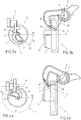
- the Figure 1 shows a disk-shaped rotary element 1, in particular in the form of a worm wheel.
- the rotary element 1 has a disk base body 11 and a collar 12 surrounding the disk base body 11.
- the narrow, annular collar 12 has a greater extent in the axial direction than the disk base body 11 and / or protrudes axially on the circumference of the disk base body 11. This protrusion preferably corresponds to at least twice the thickness of the disk base body 11.
- a drive 3, in particular an electric motor, is equipped with a drive shaft 11 that can rotate around the axis of rotation 15, which is tangential to the circumference of the rotation element 1 and / or perpendicular to the axis of rotation 4 is oriented.
- Corresponding tooth profiles 14 on the circumference of the drive shaft 11 and on the outer, radial lateral surface of the collar interlock in order to transmit a rotation and a torque of the drive 3 to the rotary element 1, which is thereby caused to rotate.
- a ramp 5 is provided on the preferably flat surface of the disk base body 11 (in Fig. 1 hatched), which extends from the surface inside the circular top in the axial direction to form an inclined formation on the rotary member 1.
- a cylindrical sleeve 16, which forms part of a bearing of the rotary element 1, and / or a projection 17 with a cylinder-like jacket surface 18 is also provided on this surface of the disk base body 11.
- the projection 17 and / or the ramp 5 extends around the sleeve 16.
- the ramp 5 preferably extends around the projection 17.
- the projection 17 protrudes beyond the ramp in the direction of the axis of rotation 4.
- the ramp 5 preferably forms the projection 17 and / or the sleeve 16, optionally together with the rotational body, is a one-piece or at least one-piece structure, which is in particular frustoconical.
- the structure has the overall shape of a non-rotationally symmetrical volcanic cone that becomes steeper in the direction of rotation.
- the ramp rests on the surface of the disk base body 11 and wraps itself spirally around the projection 17, the projection 17 and the ramp having a continuously larger radius and a steadily increasing radial extent in the circumferential direction.
- An axial upper end 7 of the ramp 5 is at an increasing distance in the circumferential direction from the surface of the disk base body 11 and at the same time from the axis of rotation 4, which creates a spiral shape.
- the lever 2 is mounted pivotably about a pivot axis 6 which is oriented perpendicular to the axis of rotation 4 and / or is spaced apart from the axis of rotation 1 by at least half the diameter of the rotary element.
- the lever 2 has a tubular part 19 for mounting around the pivot axis 6.
- the pivot axis 6 is arranged below the rotary element 1.
- the lever 2 extends perpendicular to the tubular part 19 and / or perpendicular to the pivot axis 6 with a hook shape, in particular J-shaped, and can reach from below over the collar 12 to the lower surface of the disk base body 11, around the ramp 5 with the free Contact end of 8.
- the free end 8 of the lever 2 is preferably thickened in the direction of the pivot axis 6 in order to enable particularly reliable actuation with a particularly high degree of efficiency through the ramp 5.
- the free end 8 lies directly on or almost on the surface of the disk base body 11.
- the Figure 2a shows the lever 2 and the rotary element 1 with the ramp 5 present on it in a top view in the starting position ⁇ 0 of the rotary element 1.
- the surface of the disk base body 11 or the ramp 5 in the starting position ⁇ 0 of the rotary element 1 has an end region of the free end 8, which is closest to the axis of rotation 4 in the direction of the pivot axis 6, contacted.
- the Figure 2b shows the arrangement of the locking system of Figure 2a in a side view.
- the free end 8 has the shape of a finger and a rounded, preferably an approximately semicircular end which contacts the ramp 5 or is preferably only spaced from the ramp 5 by a small air gap in order to protect the free end 8 from wear.
- the Figures 3a and 3b now show compared to the Figures 2a and 2b pivoting of the lever 2 through the ramp 5, which is contacted at a contact point 9 by the free end 8 of the lever 2 and displaces the lever 2 as a result of the rotation from the starting position ⁇ 0 into the intermediate position ⁇ i shown.
- the power transmission takes place in the direction of an actuation vector 10.
- the actuation vector 10 extends approximately along the free end 8 of the lever 2, which indicates a power transmission with a high degree of efficiency and little mechanical losses.
- the Figures 4a and 4b now show compared to the Figures 3a and 3b a continuation of the pivoting of the lever 2 through the ramp 5 by the rotation from the intermediate position ⁇ i into the intermediate position ⁇ k .
- the actuation vector 10 in the direction of which the force from the ramp 5 acts on the free end 8 of the lever 2, becomes steeper when the rotary element 1 is rotated by the drive 3.
- the actuation vector 10 is perpendicular to a connecting line 20 from the pivot axis 6 of a contact point 9 between the lever 2 and the ramp 5, at which the free end 8 contacts the ramp 5.
- the lever 2 By rotating the rotating element 1 in the direction of rotation shown in the figures (clockwise), the lever 2 is actuated, which in turn interacts with a locking mechanism, not shown.
- the contact points 9 together form a spiral shape around the axis of rotation with an increasing radius.
Landscapes
- Lock And Its Accessories (AREA)
Abstract
Description
- Die Erfindung betrifft ein Schließsystem für ein Kraftfahrzeug mit einem scheibenförmigen Rotationselement, einem Antrieb zum Rotieren des Rotationselements um eine Rotationsachse und einem Hebel, der durch das Rotationselement bewegt werden kann.
- Ein Schließsystem für ein Kraftfahrzeug wird allgemein eingesetzt, um ein unplanmäßiges Öffnen einer Tür oder Klappe eines Kraftfahrzeugs zu verhindern. Dazu wird in der Regel ein Schließbolzen einer Tür oder Klappe von einer Drehfalle eines Gesperres aufgenommen und im geschlossenen Zustand des Gesperres von einer Sperrklinke gehalten, so dass sich die Tür oder Klappe nicht mehr öffnen kann. Zum automatisierten Öffnen des Gesperres des Schließsystems kann ein Antrieb vorgesehen werden, der über z.B. ein Schneckengetriebe ein scheibenförmiges Rotationselement in Form eines Schneckenrads in Rotation versetzen kann, das wiederum mithilfe eines Nockens einen Hebel betätigt. Der Hebel kann durch eine solche Betätigung die Sperrklinke von der Drehfalle lösen, so dass die Tür oder Klappe wieder geöffnet werden kann. Die zum automatisierten Öffnen benötigte elektrische Energie für den Antrieb wird in der Regel durch eine Energiequelle des Kraftfahrzeugs bereitgestellt.
- Für ein Schließsystem ist der zur Verfügung stehende Bauraum häufig begrenzt. Die Druckschrift
DE112009001288T5 offenbart eine Schlossanordnung für ein Kraftfahrzeug, bei dem ein Zahnrad mit einem Vorsprung und ein mit dem Vorsprung wechselwirkender Sperrklinkenhebel jeweils um 90° versetzte Drehachsen aufweisen. Die Wechselwirkung erfolgt seitlich zur Drehachse des Zahnrads. - Es wird ferner auf die Druckschriften
DE102016108565A1 undDE102016108568 A1 hingewiesen. - Es ist Aufgabe der Erfindung, ein weiterentwickeltes Schließsystem bereitzustellen.
- Zur Lösung der Aufgabe dient ein Schließsystem gemäß Anspruch 1. Vorteilhafte Ausführungsformen ergeben sich aus den Unteransprüchen.
- Zur Lösung der Aufgabe dient ein Schließsystem für ein Kraftfahrzeug mit einem scheibenförmigen Rotationselement, einem Antrieb zum Rotieren des Rotationselements um eine Rotationsachse und einem Hebel, der durch das Rotationselement bewegt werden kann. Auf dem scheibenförmigen Rotationselement ist eine Rampe vorgesehen, d.h., vorhanden. Das Schließsystem ist so eingerichtet, dass der Hebel durch die Rampe verschwenkt werden kann, wenn das Rotationselement durch den Antrieb rotiert wird.
- Durch das Vorsehen einer Rampe auf dem scheibenförmigen Rotationselement zum Verschwenken des Hebels können zwei Vorteile gleichzeitig erzielt werden.
- Einerseits erlauben das Rotationselement und der Hebel eine besonders flexible Anordnung relativ zueinander und ermöglichen so ein kompaktes Einpassen des Schließsystems in eine vorgegebene Bauraumgeometrie. Beispielsweise ist ein Kraftfahrzeugschloss als das Schließsystems oder als ein Teil davon in eine L-förmige Bauraumgeometrien oder ein entsprechend L-förmig geformtes Gehäuse unterzubringen. Durch die Rampe auf dem scheibenförmigen Rotationselement können eine Schwenkachse des Hebels gegenüber der Rotationsachse des Rotationselements zueinander winkelversetzt angeordnet und gelagert werden. Auf diese Weise kann diese Anordnung gewissermaßen um die Ecke platziert werden. Dies ist von besonderem Vorteil, wenn in einem Schenkel eines L-förmigen Gehäuses das Gesperre und in dem anderen Schenkel ein Anschluss zu einer elektrischen Energiequelle liegt. Der Hebel, der insbesondere mit dem Gesperre wechselwirkt, und der Antrieb, der an eine elektrische Energiequelle anzuschließen ist, können dann in unterschiedlichen Schenkeln des L-förmigen Gehäuses eingebaut werden.
- Andererseits erlaubt das Vorsehen einer Rampe auf dem scheibenförmigen Rotationselement ein Verschwenken und damit Betätigen des Hebels mit besonders geringen mechanischen Verlusten aus der Wechselwirkung des Hebels mit der Rampe. Ein sehr hoher Wirkungsgrad des automatisierten Schließsystems kann so erzielt werden. Zum Betrieb des Schließsystems wird dann weniger elektrische Energie benötigt.
- Ein Schließsystem kann ein Kraftfahrzeugschloss für eine Tür oder Klappe und/oder ein Teil einer Zentralverriegelungsanlage oder Zuziehhilfe für ein Kraftfahrzeug sein. Bevorzugt umfasst ein Schließsystem für ein Kraftfahrzeug ein Gesperre, das in einem geschlossenen Zustand eine Tür oder Klappe in einer geschlossenen Position halten kann und in einem geöffneten Zustand ein Öffnen der Tür oder Klappe aus der geschlossenen Position zulässt. Der Hebel kann zum Wechselwirken mit dem Rotationselement in Kontakt mit der Rampe gebracht werden, d.h. die Rampe unmittelbar berühren und bei einer Rotation des Rotationselements an der Rampe entlangschleifen. Somit kann der Hebel durch eine Rotationsbewegung des Rotationselements in Abhängigkeit von dem (geometrischen) Verlauf der Rampe bewegt werden, um das Gesperre in den geöffneten oder geschlossenen Zustand zu bringen.
- Ein scheibenförmiges Rotationselement kann z.B. ein Zahnrad oder ein Schneckenrad sein. Der Einsatz eines Schneckenrads als das scheibenförmige Rotationselement ermöglicht eine flexible und kompakte Bauweise. Ein scheibenförmiges Rotationselement hat allgemein einen Durchmesser, der größer ist als eine Dicke des scheibenförmigen Rotationselements. Der Antrieb umfasst bevorzugt einen Elektromotor und eine Antriebswelle, die vorzugsweise unmittelbar das scheibenförmige Rotationselement antreibt. In einer Ausgestaltung sind das Schließsystem und der Antrieb so eingerichtet, dass das Rotationselement durch den Antrieb in zwei Rotationsrichtungen rotiert werden kann. Dies ermöglicht ein automatisiertes Zurücksetzen des Rotationselements in eine Ausgangsstellung oder ein automatisiertes Verrasten und Lösen einer Drehfalle eines Gesperres des Schließsystems. In einer Ausgestaltung ist ein automatisiertes Rotieren des Rotationselements durch den Antrieb nur in eine Rotationsrichtung möglich. Ein Zurücksetzen und/oder Verrasten einer Drehfalle erfolgt dann über eine vom Benutzer aufgewendete Kraft und/oder einen mechanischen Energiespeicher wie z.B. eine Feder.
- Ein Hebel kann allgemein um eine Schwenkachse verschwenkt werden, um eine Kraft und/oder Bewegung zu übertragen. Ein Verschwenken des Hebels durch die Rampe erfolgt grundsätzlich durch einen Kontakt, also eine unmittelbare Berührung, zwischen dem Hebel und der Rampe. Wenn das Rotationselement durch den Antrieb rotiert wird, schleift dann der Hebel entlang der Rampe. In dem vorliegenden Schließsystem kann der Hebel z.B. eine Sperrklinke zum Verrasten der Drehfalle, ein Blockadehebel zum Halten der Sperrklinke in einer die Drehfalle verrastenden Stellung, ein Auslösehebel zum Lösen der Sperrklinke oder des Blockadehebels oder ein anderes Gesperreelemente sein. Eine Sperrklinke als Hebel ermöglicht ein Schließsystem mit besonders wenigen Gesperrekomponenten. In Kombination mit einem automatisieren Antreiben in beide Rotationsrichtungen kann besonders schnell und zuverlässig eine Drehfalle verrastet und entrastet werden. Ein Auslösehebel als Hebel ermöglicht ein besonders energieeffizientes Auslösen eines Gesperres, insbesondere in Kombination mit einem Blockadehebel und/oder einem automatisierten Antreiben des Rotationselements in nur eine Drehrichtung.
Eine Rampe ist allgemein eine schräge Führungs- oder Betätigungsfläche. Eine Rampe ist keine Fase einer Kante und auch keine herstellungsbedingte Schräg oder Rundung einer Ecke. Insbesondere wird die Rampe durch einen Vorsprung gebildet, der beispielsweise einstückig mit dem Rotationselement verbunden oder hergestellt ist. Dies reduziert die Anzahl von Teilen. In einer Ausgestaltung wird die Rampe durch ein separates Bauteil gebildet, das auf dem scheibenförmigen Rotationselement vorgesehen ist. Dies ermöglicht den Einsatz unterschiedlicher Materialien für die Rampe und das Rotationselement und eine Reduzierung der Herstellungskosten. Die Rampe bzw. das die Rampe bildende separate Bauteil ist dann so mit dem Rotationselement verbunden oder gekoppelt, dass die Rampe gemeinsam mit dem Rotationselement rotiert werden kann. Wenn die Rampe durch ein separates Bauteil bereitgestellt wird, erfolgt vorzugsweise eine bewegungsfest oder zumindest drehfest Verbindung mit dem Rotationselement. Eine Rampe, die auf dem scheibenförmigen Rotationselement vorgesehen ist, befindet sich in axialer Richtung von dem Rotationselement, also in Richtung der Rotationsachse. Die Rampe ist also an einer Oberseite des scheibenförmigen Rotationselements angeordnet. Die Oberseite bezieht sich auf eine Oberfläche eines Scheibengrundkörpers, auf der die Rampe vorgesehen ist. Die Oberseite bezieht sich nicht auf einen den Scheibengrundkörper umgebenden Kragen, der beispielsweise zum Wechselwirken mit einer Antriebswelle des Antriebs vorgesehen ist und eine größere axiale Ausdehnung hat als der Scheibengrundkörper. - In einer Ausführungsform verläuft die Rampe schräg zur Rotationsachse und/oder fällt in radialer Richtung, bezogen auf die Rotationsachse, zum Rotationselement hin ab. Die Rampe hat also im Wesentlichen eine Form eines Mantelflächensegments eines stumpfkegelartigen Gebildes. Der Hebel kann dadurch mit einem besonders großen Wirkungsgrad betätigt werden, insbesondere bei einer zur Rotationsachse geneigten Schwenkachse des Hebels. Insbesondere ist die Rampe in einer Weise schräg geformt, dass der Hebel durch ein Führen, Gleiten und/oder Schleifen entlang der Rampe von dem Rotationselement weg verdrängt wird. Vorzugsweise trifft die Rampe schräg auf eine Oberseite des scheibenförmigen Rotationselements, die der Rampe zugewandt ist. Insbesondere befindet sich die Rampe vollständig innerhalb des Umfangs des scheibenförmigen Rotationselements, auf dem die Rampe vorgesehen ist. Die Rampe ragt also an keiner Stelle radial über den äußeren Umfang des Rotationselements.
- In einer Ausführungsform verläuft die Rampe in Umfangrichtung gebogen um die Rotationsachse. Ein besonders gezieltes Verschwenken des Hebels in Abhängigkeit von dem Verlauf der Rampe in Umfangrichtung kann so durch eine Rotation des Rotationselementes ermöglicht werden. Insbesondere verläuft die Rampe über einen Winkelbereich von höchstens 270°, bevorzugt 235°, besonders bevorzugt höchstens 205°, um die Rotationsachse. Eine besonders schnelle Reaktionszeit kann so erzielt werden.
- In einer Ausführungsform verläuft ein axiales oberes Ende der Rampe spiralförmig um die Rotationsachse. Durch das Rotieren des Rotationselements kann dadurch der Hebel mit besonders geringen Reibungsverlusten verschwenkt werden. Ein axiales oberes Ende der Rampe bezieht sich auf einen Längsschnitt entlang der Rotationsachse des Rotationselements und meint den Punkt, der axial am weitesten von der Oberseite des scheibenförmigen Rotationselements entfernt ist. In einer Ausführungsform, in der die Rampe auf die Oberseite des scheibenförmigen Rotationselements trifft, entspricht die axiale Ausdehnung der Rampe exakt dem axialen Abstand von der Oberseite des scheibenförmigen Rotationselements bis zum axialen oberen Ende der Rampe. Dieser axiale Abstand und/oder diese axiale Ausdehnung ändern sich in Abhängigkeit von der Winkelposition, der zusammen mit der Rotationsachse die Ebene des oben erwähnten Längsschnitts aufspannt. Das axiale obere Ende der Rampe entfernt sich also zunehmend von dem scheibenförmigen Rotationselement in Richtung der Rotationsachse relativ zu dem Hebel mit einer festen Winkelposition, wenn das Rotationselement durch den Antrieb vorzugsweise zum Verschwenken des Hebels von dem Rotationselement weg rotiert wird.
- In einer Ausgestaltung nimmt die radiale Ausdehnung der Rampe in Umfangrichtung betrachtet zu. Die Zuverlässigkeit des Schließsystems wird so erhöht.
- In einer Ausführungsform, nimmt ein radialer Abstand von der Rotationsachse bis zum axialen oberen Ende der Rampe in Umfangrichtung betrachtet zu. Der Hebel kann dadurch besonders weit verschwenkt werden, und dies bei einem besonders hohen Wirkungsgrad.
- In einer Ausführungsform enthält die Rampe eine konkave Form, insbesondere im Längsschnitt betrachtet. Ein weiter optimierter Betätigungsvektor kann so erhalten werden.
- In einer Ausgestaltung ist ein Vorsprung mit einer zylinderartigen Mantelfläche vorgesehen, d.h., die Mantelfläche erstreckt sich gebogen um die Rotationsachse und parallel zur Rotationsachse. Insbesondere hat der Vorsprung eine größere axiale Ausdehnung als die Rampe. Das axiale obere Ende der Rampe kann dann auf der zylinderartigen Mantelfläche liegen. Die Rampe schließt dann im Längsschnitt entlang der Rotationsachse betrachtet einen stumpfen Winkel mit der Rampe ein. Eine besonders robuste Rampe kann so erhalten werden.
- In einer Ausführungsform kann der Hebel durch die Rampe um eine Schwenkachse verschwenkt werden, die axial von der Rampe beabstandet ist. Durch die axial beabstandete Schwenkachse wird ein besonders effektives Verschwenken des Hebels ermöglicht.
- In einer Ausführungsform ist die Schwenkachse zur Rotationsachse um eine Winkeldifferenz geneigt. Insbesondere beträgt die Winkeldifferenz mindestens 45° und/oder höchstens 135°, besonders bevorzugt genau 90°. Eine kompakte Bauweise in einen vorgegebenen Bauraum kann so bei gleichzeitig geringem Energieverbrauch des Antriebs erreicht werden. Ein minimaler Energieverbrauch ist bei einer Winkeldifferenz zwischen 85° und 95° möglich.
- In einer Ausführungsform wird der Hebel durch die Rampe axial verdrängt, wenn das Rotationselement durch den Antrieb rotiert wird. Ein besonders zuverlässiges Betätigen des Hebels wird so ermöglicht. Axial verdrängt meint in Richtung der Rotationsachse, insbesondere von dem scheibenförmigen Rotationselement weg.
- In einer Ausführungsform ist der Hebel gekrümmt, L-förmig, hakenförmig oder J-förmig geformt. Ein besonders hoher Wirkungsgrad kann so bei der Betätigung durch die Rampe erzielt werden. Zudem kann ein besonders kompaktes Schließsystem bereitgestellt werden.
- In einer Ausführungsform kann der Hebel von unterhalb des scheibenförmigen Rotationselements über das scheibenförmige Rotationselement greifen und die Rampe kontaktieren. Der Hebel kann also einen ringförmigen Kragen am äußeren Umfang des Rotationselementes, der insbesondere axial dicker ist als der Scheibengrundkörper des Rotationselements, umgreifen. Der Hebel kann dabei über die Oberseite des Rotationselementes bis zur radial innenliegenden Rampe greifen, um die Rampe zu kontaktieren. Insbesondere wird der Hebel vorzugsweise durch eine Feder gegen die Rampe gedrückt, um die Rampe zu kontaktieren.
- In einer Ausgestaltung ist das freie Ende des Hebels abgerundet. Vorzugsweise weist das freie Ende des Hebels im Querschnitt durch die Schwenkachse betrachtet eine näherungsweise halbkreisform auf. Hierdurch kann der Reibwiderstand reduziert werden.
- In einer Ausführungsform gleitet oder schleift ein freies Ende des Hebels relativ zum Rotationselement spiralförmig entlang der Rampe, wenn das Rotationselement durch den Antrieb rotiert wird. Ein sich an die Bewegung des Hebels und des freien Endes angepasster Betätigungsvektor mit besonders geringen Reibungsverlusten kann so erhalten werden.
- In einer Ausführungsform wird ein Steigungswinkel der Rampe stetig flacher, wenn das Rotationselement durch den Antrieb rotiert wird, vorzugsweise in eine Rotationsrichtung zum Verschwenken des Hebels von der Rotationsachse weg und/oder zum Betätigen des Hebels. Ein besonders hoher Wirkungsgrad kann so während der Betätigung trotz der Relativbewegung zwischen der Rampe und dem Hebel erzielt werden.
- In einer Ausführungsform wird ein radialer Abstand zwischen der Rotationsachse und einer Kontaktstelle zwischen dem freien Ende des Hebels und der Rampe stetig größer, wenn das Rotationselement durch den Antrieb rotiert wird, vorzugsweise in eine Rotationsrichtung zum Verschwenken des Hebels von der Rotationsachse weg und/oder zum Betätigen des Hebels. Ein besonders großer Verschwenkwinkel des betätigten Hebels kann so realisiert werden.
- In einer Ausgestaltung weist die Rampe einen Steigungswinkel von mindestens 20° und/oder höchstens 80° auf, insbesondere innerhalb eines Flächenbereiches, über den das freie Ende gleitet oder schleift, das Rotationselement durch den Antrieb rotiert wird. Reibungsverluste können so reduziert werden, insbesondere in Kombination mit einem abgerundeten freien Ende des Hebels, das die Rampe mit den genannten Steigungswinkeln kontaktiert.
In einer Ausgestaltung nimmt der Steigungswinkel der Rampe in Umfangrichtung entlang einer Bahn, die das freie Ende des Hebels bei der Rotation des Rotationselements an der Rampe entlang gleitet oder schleift, stetig zu, insbesondere von 20° bis 80°. Der Steigungswinkel kann so an die Relativbewegung und die Änderung der Orientierung des freien Endes zur Rampe im Bereich der Kontaktstelle zur Optimierung des Wirkungsgrades angepasst werden, wobei die Relativbewegung und die Orientierungsänderung durch das Verschwenken des Hebels hervorgerufen wird. Die Steigung wird zu einer Ebene gemessen, die senkrecht zur Rotationsachse verläuft. Insbesondere wir die Steigung zur Oberseite des scheibenförmigen Rotationselements gemessen. Grundsätzlich ist die Rotationsachse senkrecht zur Oberseite des Rotationselements orientiert. - Insbesondere bezieht sich in diesem Dokument die Rotationsrichtung auf die Drehrichtung um die Rotationsachse, die zu einem Verschwenken des Hebels von der Rotationsachse weg und/oder zum Betätigen des Hebels führt. Die entgegengesetzte Drehrichtung ist dann die Rückwärtsrotationsrichtung. Ein Betätigen des Hebels führt bevorzugt zum Auslösen des Gesperres, so dass z.B. eine Tür oder Klappe eines Kraftfahrzeugs wieder geöffnet werden kann. Eine Rotation des Rotationselements in die Rückwärtsrotationsrichtung dient in einer Ausgestaltung der Rückstellung des Hebels und/oder des Rotationselements in eine Ausgangsstellung. Alternativ oder ergänzend kann eine Rotation des Rotationselements in die Rückwärtsrotationsrichtung einem Verrasten einer Drehfalle dienen, um ein Gesperre in einen geschlossenen Zustand zu bringen, in dem z.B. eine Tür oder Klappe eines Kraftfahrzeugs sicher in einer geschlossen Position gehalten werden.
- Nachfolgend werden Ausführungsbeispiele der Erfindung auch anhand von Figuren näher erläutert. Merkmale der Ausführungsbeispiele und weiterer nachfolgend beschriebener alternativer oder ergänzender Ausgestaltungen können einzeln oder in einer Mehrzahl mit dem beanspruchten Gegenstand kombiniert werden. Die beanspruchten Schutzbereiche sind nicht auf die Ausführungsbeispiele beschränkt.
- Es zeigen:
- Figur 1:
- Isometrische Darstellung eines Antriebs zum Rotieren eines Rotationselements, das sich in einer Ausgangsstellung α0 befindet und über eine Rampe auf dem Rotationselement einen Hebel verschwenken kann;
- Figur 2a:
- Schematische Draufsicht auf die Anordnung der
Fig. 1 in der Ausgangsstellung α0; - Figur 2b:
- Seitliche Darstellung der Anordnung der
Figur 2a ; - Figur 3a:
- Schematische Draufsicht auf die Anordnung der
Fig. 2a während eines Rotierens des Rotationselements, gezeigt in einer ersten Zwischenstellung αi; - Figur 3b:
- Seitliche Darstellung der Anordnung der
Figur 3a ; - Figur 4a:
- Schematische Draufsicht auf die Anordnung der
Figur 3a während des Rotierens des Rotationselements, gezeigt in einer zweiten Zwischen stellung αk; - Figur 4b:
- Seitliche Darstellung der Anordnung der
Figur 4a . - Die
Figur 1 zeigt ein scheibenförmiges Rotationselement 1, insbesondere in Form eines Schneckenrads. Das Rotationselement 1 weist einen Scheibengrundkörper 11 und einen den Scheibengrundkörper 11 umgebenden Kragen 12 auf. Der schmale, ringförmige Kragen 12 hat in axialer Richtung eine größere Ausdehnung als der Scheibengrundkörper 11 und/oder steht am Umfang des Scheibengrundkörpers 11 axial hervor. Dieser Überstand entspricht bevorzugt mindestens der doppelten Dicke des Scheibengrundkörpers 11. Ein Antrieb 3, insbesondere ein Elektromotor, ist mit einer Antriebsachse 11 ausgestattet, die sich um die Drehachse 15 drehen kann, die tangential zum Umfang des Rotationselements 1 und/oder senkrecht zur Rotationsachse 4 orientiert ist. Zueinander korrespondierende Zahnprofile 14 am Umfang der Antriebsachse 11 und an der äußeren, radialen Mantelfläche des Kragens greifen ineinander, um eine Drehung und ein Drehmoment des Antriebs 3 auf das Rotationselement 1 zu übertragen, das dadurch zum Rotieren gebracht wird. - Auf der bevorzugt ebenen Oberfläche des Scheibengrundkörpers 11 ist eine Rampe 5 vorhanden (in
Fig. 1 schraffiert), die sich von der Oberfläche innerhalb der kreisförmigen Oberseite in axiale Richtung erstreckt, um eine schräge Ergebung auf dem Rotationselement 1 zu bilden. Ebenfalls auf diese Oberfläche des Scheibengrundkörpers 11 ist eine zylinderförmige Hülse 16, die Teil eines Lagers des Rotationselements 1 bildet, und/oder ein Vorsprung 17 mit einer zylinderartigen Mantelfläche 18 vorgesehen. Insbesondere erstreckt sich der Vorsprung 17 und/oder die Rampe 5 um die Hülse 16. Vorzugsweise erstreckt sich die Rampe 5 um den Vorsprung 17. Insbesondere überragt der Vorsprung 17 die Rampe in Richtung der Rotationsachse 4. Bevorzugt bilden die Rampe 5, der Vorsprung 17 und/oder die Hülse 16 optional gemeinsam mit dem Rotationskörper ein einstückiges oder zumindest einteiliges Gebilde, das insbesondere stumpfkegelartig ist. Das Gebilde hat insgesamt die Gestalt eines nicht drehsymmetrischen Vulkankegels der in Umlaufrichtung steiler wird. Die Rampe fußt auf der Oberfläche des Scheibengrundkörpers 11 und wickelt sich spiralförmig um den Vorsprung 17 herum, wobei der Vorsprung 17 und die Rampe in Umfangrichtung einen stetig größeren Radius und eine stetig größer werdende radiale Ausdehnung aufweisen. Ein axiales oberes Ende 7 der Rampe 5 weist in Umfangrichtung einen zunehmenden Abstand zur Oberfläche des Scheibengrundkörpers 11 und gleichzeitig zur Rotationsachse 4 auf, wodurch eine Spiralform entsteht. - Der Hebel 2 ist um eine Schwenkachse 6 verschwenkbar gelagert, die senkrecht zur Rotationsachse 4 orientiert ist und/oder mindestens um den halben Durchmesser des Rotationselements von der Rotationsachse 1 beabstandet. Der Hebel 2 hat ein rohrförmiges Teil 19 zum Lagern um die Schwenkachse 6. Die Schwenkachse 6 ist unterhalb des Rotationselements 1 angeordnet. Senkrecht zu dem rohrförmigen Teil 19 und/oder senkrecht zur Schwenkachse 6 erstreckt sich der Hebel 2 mit einer hakenform, insbesondere J-förmig, und kann von unten über den Kragen 12 zur tiefergelegenen Oberfläche des Scheibengrundkörpers 11 greifen, um die Rampe 5 mit dem freien Ende 8 zu kontaktieren. Bevorzugt ist das freie Ende 8 des Hebels 2 in Richtung der Schwenkachse 6 aufgedickt, um ein besonders zuverlässiges Betätigen mit besonders hohem Wirkungsgrad durch die Rampe 5 zu ermöglichen. In einer Ausgangsstellung α0 des Rotationselements 1 liegt das freie Ende 8 unmittelbar auf oder beinahe auf der Oberfläche des Scheibengrundkörpers 11.
- Die
Figur 2a zeigt den Hebel 2 und das Rotationselement 1 mit der darauf vorhandenen Rampe 5 in der Draufsicht in der Ausgangsstellung α0 des Rotationselements 1. In einer Ausgestaltung wird die Oberfläche des Scheibengrundkörpers 11 oder die Rampe 5 in der Ausgangsstellung α0 des Rotationselements 1 mit einem Endbereich des freien Ende 8, der in Richtung der Schwenkachse 6 am nächsten zur Rotationsachse 4 liegt, kontaktiert. DieFigur 2b zeigt die Anordnung des Schließsystems derFigur 2a in einer Seitendarstellung. Das freie Ende 8 hat im Querschnitt die Form eines Fingers und ein gerundetes, bevorzugt annährend halbkreisförmiges Ende, das die Rampe 5 kontaktiert oder bevorzugt nur durch eine kleinen Luftspalt von der Rampe 5 beabstandet ist, um das freie Ende 8 vor Abnutzung zu schützen. - Die
Figuren 3a und 3b zeigen nun im Vergleich zu denFiguren 2a und 2b ein Verschwenken des Hebels 2 durch die Rampe 5, die an einer Kontaktstelle 9 von dem freien Ende 8 des Hebels 2 kontaktiert wird und den Hebel 2 infolge der Rotation von der Ausgangsstellung α0 in die gezeigte Zwischenstellung αi verdrängt. Die Kraftübertragung erfolgt in Richtung eines Betätigungsvektors 10. Der Betätigungsvektor 10 erstreckt sich näherungsweise entlang des freien Endes 8 des Hebels 2, was eine Kraftübertragung mit hohem Wirkungsgrad und wenig mechanischen Verlusten indiziert. - Die
Figuren 4a und 4b zeigen nun im Vergleich zu denFiguren 3a und 3b eine Fortsetzen des Verschwenken des Hebels 2 durch die Rampe 5 durch die Rotation von der Zwischenstellung αi in die Zwischenstellung αk. Der Betätigungsvektor 10, in dessen Richtung die Kraft von der Rampe 5 auf das freie Ende 8 des Hebels 2 wirkt, wird steiler, wenn das Rotationselement 1 durch den Antrieb 3 rotiert wird. Der Betätigungsvektor 10 steht senkrecht auf einer Verbindungslinie 20 von der Schwenkachse 6 einer Kontaktstelle 9 zwischen dem Hebel 2 und der Rampe 5, an der das freie Ende 8 die Rampe 5 kontaktiert. - Durch die Rotation des Rotationselementes 1 in die in den Figuren gezeigte Rotationsrichtung (im Uhrzeigersinn) wird der Hebel 2 betätigt, der wiederum mit einem nicht gezeigten Gesperre wechselwirkt. Die Kontaktstellen 9 bilden dabei gemeinsam eine Spiralform um die Rotationsachse mit zunehmendem Radius.
-
- 1
- Rotationselement
- 2
- Hebel
- 3
- Antrieb
- 4
- Rotationsachse
- 5
- Rampe
- 6
- Schwenkachse
- 7
- Axiales oberes Ende der Rampe
- 8
- Freies Ende des Hebels
- 9
- Kontaktstelle
- 10
- Betätigungsvektor
- 11
- Scheibengrundkörper
- 12
- Kragen
- 13
- Antriebsachse
- 14
- Zahnprofil
- 15
- Drehachse
- 16
- Hülse
- 17
- Vorsprung
- 18
- Mantelfläche des Vorsprungs
- 19
- Rohrförmiges Teil des Hebels
- 20
- Verbindungslinie
- α0
- Ausgangsstellung
- αi , αk
- Zwischenstellungen
Claims (10)
- Schließsystem für ein Kraftfahrzeug mit einem scheibenförmigen Rotationselement (1), einem Antrieb (3) zum Rotieren des Rotationselements (1) um eine Rotationsachse (4) und einem Hebel (2), der durch das Rotationselement (1) bewegt werden kann, dadurch gekennzeichnet, dass auf dem scheibenförmigen Rotationselement (1) eine Rampe (5) vorgesehen ist und das Schließsystem so eingerichtet ist, dass der Hebel (2) durch die Rampe (5) verschwenkt werden kann, wenn das Rotationselement (1) durch den Antrieb (3) rotiert wird.
- Schließsystem nach dem vorhergehenden Anspruch, dadurch gekennzeichnet, dass die Rampe (5) schräg zur Rotationsachse (4) verläuft und in radialer Richtung zum Rotationselement (1) hin abfällt.
- Schließsystem nach einem der vorhergehenden Ansprüche, dadurch gekennzeichnet, dass die Rampe (5) in Umfangrichtung gebogen um die Rotationsachse (4) verläuft.
- Schließsystem nach einem der vorhergehenden Ansprüche, dadurch gekennzeichnet, dass ein axiales oberes Ende (7) der Rampe (5) spiralförmig um die Rotationsachse (4) verläuft.
- Schließsystem nach dem vorhergehenden Anspruch, dadurch gekennzeichnet, dass in Umfangrichtung betrachtet ein radialer Abstand von der Rotationsachse (4) bis zum axialen oberen Ende (7) der Rampe (5) und/oder eine radiale Ausdehnung der Rampe (5) zunehmen.
- Schließsystem nach einem der vorhergehenden Ansprüche, dadurch gekennzeichnet, dass die Rampe (5) eine konkave Form enthält.
- Schließsystem nach einem der vorhergehenden Ansprüche, dadurch gekennzeichnet, dass der Hebel (2) durch die Rampe (5) um eine Schwenkachse (6) verschwenkt werden kann, die axial von der Rampe (5) beabstandet ist, und/oder die Schwenkachse (6) zur Rotationsachse (4) um eine Winkeldifferenz geneigt ist, insbesondere um mindestens 45° und/oder höchstens 135°.
- Schließsystem nach einem der vorhergehenden Ansprüche, dadurch gekennzeichnet, dass der Hebel (2) L-förmig oder J-förmig geformt ist und/oder von unterhalb des scheibenförmigen Rotationselements (1) über das scheibenförmige Rotationselement (1) greifen und die Rampe (5) kontaktieren kann.
- Schließsystem nach einem der vorhergehenden Ansprüche, dadurch gekennzeichnet, dass ein freies Ende (8) des Hebels (2) relativ zum Rotationselement (1) spiralförmig entlang der Rampe (5) gleitet, wenn das Rotationselement (1) durch den Antrieb (3) rotiert wird.
- Schließsystem nach dem vorhergehenden Anspruch, dadurch gekennzeichnet, dass ein Steigungswinkel der Rampe (5) stetig flacher und/oder ein radialer Abstand zwischen der Rotationsachse (4) und einer Kontaktstelle (9) zwischen dem freien Ende (8) des Hebels (2) und der Rampe (5) stetig größer wird, wenn das Rotationselement (1) durch den Antrieb (3) rotiert wird.
Applications Claiming Priority (1)
| Application Number | Priority Date | Filing Date | Title |
|---|---|---|---|
| DE102019109488.7A DE102019109488A1 (de) | 2019-04-10 | 2019-04-10 | SCHLIEßSYSTEM FÜR EIN KRAFTFAHRZEUG |
Publications (2)
| Publication Number | Publication Date |
|---|---|
| EP3722543A1 true EP3722543A1 (de) | 2020-10-14 |
| EP3722543B1 EP3722543B1 (de) | 2022-05-11 |
Family
ID=70227756
Family Applications (1)
| Application Number | Title | Priority Date | Filing Date |
|---|---|---|---|
| EP20164408.5A Active EP3722543B1 (de) | 2019-04-10 | 2020-03-20 | Schliesssystem für ein kraftfahrzeug |
Country Status (4)
| Country | Link |
|---|---|
| US (1) | US11473344B2 (de) |
| EP (1) | EP3722543B1 (de) |
| CN (1) | CN111809986B (de) |
| DE (1) | DE102019109488A1 (de) |
Families Citing this family (11)
| Publication number | Priority date | Publication date | Assignee | Title |
|---|---|---|---|---|
| DE202017107026U1 (de) * | 2017-11-20 | 2018-12-21 | Inteva Products, Llc | Stellantrieb für ein Fach für eine Servosicherung |
| DE102020118721A1 (de) | 2020-07-15 | 2022-01-20 | Kiekert Aktiengesellschaft | Kraftfahrzeugschloss |
| DE102021108162A1 (de) * | 2021-03-31 | 2022-10-06 | Kiekert Aktiengesellschaft | Kraftfahrzeug-Schloss insbesondere Kraftfahrzeug-Türverschluss |
| DE102021123329A1 (de) * | 2021-09-09 | 2023-03-09 | Kiekert Aktiengesellschaft | Kraftfahrzeug-Schloss insbesondere Kraftfahrzeug-Türschloss |
| DE102021123328A1 (de) * | 2021-09-09 | 2023-03-09 | Kiekert Aktiengesellschaft | Kraftfahrzeugschloss |
| DE102021128301A1 (de) | 2021-10-29 | 2023-05-04 | Kiekert Aktiengesellschaft | Kraftfahrzeugschloss |
| DE102021128433A1 (de) | 2021-11-02 | 2023-05-04 | Kiekert Aktiengesellschaft | Kraftfahrzeug-Schloss, insbesondere Kraftfahrzeug-Türschloss |
| DE102022118120A1 (de) * | 2022-07-20 | 2024-01-25 | Kiekert Aktiengesellschaft | Antriebseinheit für kraftfahrzeugtechnische Anwendungen Kronenrand als Stellgetriebe im Schloss (Weiterentwicklung) |
| US12595689B2 (en) | 2023-08-02 | 2026-04-07 | Kiekert Ag | Motor vehicle lock, in particular motor vehicle side door lock |
| CN122407019A (zh) | 2025-01-09 | 2026-07-17 | 开开特股份公司 | 机动车锁和包括该机动车锁的车辆 |
| CN122407020A (zh) | 2025-01-09 | 2026-07-17 | 开开特股份公司 | 机动车锁和包括该机动车锁的车辆 |
Citations (6)
| Publication number | Priority date | Publication date | Assignee | Title |
|---|---|---|---|---|
| DE112009001288T5 (de) | 2008-05-27 | 2011-04-14 | Inteva Products, LLC, Troy | Fahrzeugschloss |
| US8752869B2 (en) * | 2010-04-28 | 2014-06-17 | Inteva Products Llc | Glove box actuator |
| DE102016108568A1 (de) | 2016-05-10 | 2017-11-16 | Huf Hülsbeck & Fürst Gmbh & Co. Kg | Sensorhebel für eine Sensorvorrichtung zur Erkennung zumindest einer Stellposition einer Lenkradsperre |
| DE102016108565A1 (de) | 2016-05-10 | 2017-11-16 | Huf Hülsbeck & Fürst Gmbh & Co. Kg | Umsetzungselement für eine elektrische Lenkradsperre |
| US20180258671A1 (en) * | 2017-03-13 | 2018-09-13 | Brose Schliesssysteme Gmbh & Co. Kommanditgesellschaft | Auxiliary locking drive |
| DE202017107026U1 (de) * | 2017-11-20 | 2018-12-21 | Inteva Products, Llc | Stellantrieb für ein Fach für eine Servosicherung |
Family Cites Families (9)
| Publication number | Priority date | Publication date | Assignee | Title |
|---|---|---|---|---|
| US4518181A (en) * | 1982-05-28 | 1985-05-21 | Mitsui Kinzoku Kogyo Kabushiki Kaisha | Locking device |
| DE4125448C2 (de) * | 1991-08-01 | 2003-11-06 | Continental Teves Ag & Co Ohg | Elektromotorischer Stellantrieb für eine zentrale Türverriegelungsanlage eines Kraftfahrzeugs |
| FR2821109B1 (fr) * | 2001-02-22 | 2003-04-11 | Valeo Securite Habitacle | Serrure electrique a actionnement de secours |
| WO2006060915A1 (en) * | 2004-12-10 | 2006-06-15 | Magna Closures Inc. | Power actuator |
| JP4600250B2 (ja) * | 2005-11-17 | 2010-12-15 | アイシン精機株式会社 | 車両用ドアクローザ装置 |
| JP5213190B2 (ja) * | 2010-08-20 | 2013-06-19 | 三井金属アクト株式会社 | 車両用ドアラッチ装置 |
| US9194162B2 (en) * | 2011-07-14 | 2015-11-24 | Inteva Products, Llc | Vehicle door latch |
| CN102400614A (zh) * | 2011-11-23 | 2012-04-04 | 上海恩坦华汽车门系统有限公司 | 车用电控一体化门锁保险执行器 |
| DE102014201799A1 (de) * | 2014-01-31 | 2015-08-06 | Kiekert Ag | Schließvorrichtung für eine Kraftfahrzeughaube und Verfahren |
-
2019
- 2019-04-10 DE DE102019109488.7A patent/DE102019109488A1/de not_active Withdrawn
-
2020
- 2020-03-20 EP EP20164408.5A patent/EP3722543B1/de active Active
- 2020-04-08 CN CN202010271755.0A patent/CN111809986B/zh active Active
- 2020-04-09 US US16/844,538 patent/US11473344B2/en active Active
Patent Citations (6)
| Publication number | Priority date | Publication date | Assignee | Title |
|---|---|---|---|---|
| DE112009001288T5 (de) | 2008-05-27 | 2011-04-14 | Inteva Products, LLC, Troy | Fahrzeugschloss |
| US8752869B2 (en) * | 2010-04-28 | 2014-06-17 | Inteva Products Llc | Glove box actuator |
| DE102016108568A1 (de) | 2016-05-10 | 2017-11-16 | Huf Hülsbeck & Fürst Gmbh & Co. Kg | Sensorhebel für eine Sensorvorrichtung zur Erkennung zumindest einer Stellposition einer Lenkradsperre |
| DE102016108565A1 (de) | 2016-05-10 | 2017-11-16 | Huf Hülsbeck & Fürst Gmbh & Co. Kg | Umsetzungselement für eine elektrische Lenkradsperre |
| US20180258671A1 (en) * | 2017-03-13 | 2018-09-13 | Brose Schliesssysteme Gmbh & Co. Kommanditgesellschaft | Auxiliary locking drive |
| DE202017107026U1 (de) * | 2017-11-20 | 2018-12-21 | Inteva Products, Llc | Stellantrieb für ein Fach für eine Servosicherung |
Also Published As
| Publication number | Publication date |
|---|---|
| US11473344B2 (en) | 2022-10-18 |
| DE102019109488A1 (de) | 2020-10-15 |
| US20200325706A1 (en) | 2020-10-15 |
| CN111809986A (zh) | 2020-10-23 |
| EP3722543B1 (de) | 2022-05-11 |
| CN111809986B (zh) | 2023-08-15 |
Similar Documents
| Publication | Publication Date | Title |
|---|---|---|
| EP3722543B1 (de) | Schliesssystem für ein kraftfahrzeug | |
| EP2914864B1 (de) | Antriebseinrichtung | |
| EP3394372B1 (de) | Sicherheitsvorrichtung für ein kraftfahrzeug mit einer drehfalle und einer auswurffeder | |
| EP2923418B1 (de) | Verriegelungsmechanismus für steckverbinder | |
| EP3334879B1 (de) | Elektroschloss mit betätigungseinrichtung für ein kraftfahrzeugschloss | |
| DE2437778C2 (de) | Motorisch angetriebene Betätigungsvorrichtung für ein Ventil | |
| DE10157473A1 (de) | Antriebseinheit für ein Türschloss | |
| EP3697991B1 (de) | Kraftfahrzeugschliesssystem mit elektrischer öffnungseinrichtung | |
| EP2034383A2 (de) | Drehsteller | |
| DE102004020655A1 (de) | Verriegelungseinheit für ein bewegliches Schließelement | |
| DE102008061524A1 (de) | Mehrklinken-Gesperre mit Rasthaken | |
| DE112008001336T5 (de) | Verbindungsvorrichtungen | |
| DE102016201177A1 (de) | Parksperrenvorrichtung für ein Fahrzeuggetriebe | |
| DE10104591B4 (de) | Motor mit Kupplung | |
| DE10350698B4 (de) | Kupplungsmechanismus | |
| EP3784855B1 (de) | Kraftfahrzeugschloss | |
| WO2007076826A1 (de) | Kraftfahrzeugtürschloss | |
| DE102021102559A1 (de) | Elektromotorischer Antrieb für kraftfahrzeug-technische Anwendungen | |
| DE19858874B4 (de) | Elektrischer Drehschalter | |
| WO2020253912A1 (de) | SCHLIEßEINRICHTUNG FÜR EIN KRAFTFAHRZEUG | |
| EP1957818B1 (de) | Verstellmechanismus für einen Fahrzeugsitz | |
| DE102005061791A1 (de) | Verriegelungseinheit, insbesondere für eine Überlagerungslenkung | |
| DE102024122699A1 (de) | Aktor zum Antreiben eines Scheibenwischers | |
| AT514539B1 (de) | Sicherheitseinrichtung für Verriegelungseinrichtungen | |
| WO2012130206A2 (de) | Verriegelungseinrichtung für ein kraftfahrzeug |
Legal Events
| Date | Code | Title | Description |
|---|---|---|---|
| PUAI | Public reference made under article 153(3) epc to a published international application that has entered the european phase |
Free format text: ORIGINAL CODE: 0009012 |
|
| STAA | Information on the status of an ep patent application or granted ep patent |
Free format text: STATUS: THE APPLICATION HAS BEEN PUBLISHED |
|
| AK | Designated contracting states |
Kind code of ref document: A1 Designated state(s): AL AT BE BG CH CY CZ DE DK EE ES FI FR GB GR HR HU IE IS IT LI LT LU LV MC MK MT NL NO PL PT RO RS SE SI SK SM TR |
|
| AX | Request for extension of the european patent |
Extension state: BA ME |
|
| STAA | Information on the status of an ep patent application or granted ep patent |
Free format text: STATUS: REQUEST FOR EXAMINATION WAS MADE |
|
| 17P | Request for examination filed |
Effective date: 20210212 |
|
| RBV | Designated contracting states (corrected) |
Designated state(s): AL AT BE BG CH CY CZ DE DK EE ES FI FR GB GR HR HU IE IS IT LI LT LU LV MC MK MT NL NO PL PT RO RS SE SI SK SM TR |
|
| RIC1 | Information provided on ipc code assigned before grant |
Ipc: E05B 81/30 20140101ALI20210923BHEP Ipc: E05B 81/42 20140101AFI20210923BHEP |
|
| GRAP | Despatch of communication of intention to grant a patent |
Free format text: ORIGINAL CODE: EPIDOSNIGR1 |
|
| STAA | Information on the status of an ep patent application or granted ep patent |
Free format text: STATUS: GRANT OF PATENT IS INTENDED |
|
| INTG | Intention to grant announced |
Effective date: 20211112 |
|
| GRAS | Grant fee paid |
Free format text: ORIGINAL CODE: EPIDOSNIGR3 |
|
| GRAA | (expected) grant |
Free format text: ORIGINAL CODE: 0009210 |
|
| STAA | Information on the status of an ep patent application or granted ep patent |
Free format text: STATUS: THE PATENT HAS BEEN GRANTED |
|
| AK | Designated contracting states |
Kind code of ref document: B1 Designated state(s): AL AT BE BG CH CY CZ DE DK EE ES FI FR GB GR HR HU IE IS IT LI LT LU LV MC MK MT NL NO PL PT RO RS SE SI SK SM TR |
|
| REG | Reference to a national code |
Ref country code: GB Ref legal event code: FG4D Free format text: NOT ENGLISH |
|
| REG | Reference to a national code |
Ref country code: CH Ref legal event code: EP |
|
| REG | Reference to a national code |
Ref country code: AT Ref legal event code: REF Ref document number: 1491541 Country of ref document: AT Kind code of ref document: T Effective date: 20220515 |
|
| REG | Reference to a national code |
Ref country code: DE Ref legal event code: R096 Ref document number: 502020001079 Country of ref document: DE |
|
| REG | Reference to a national code |
Ref country code: IE Ref legal event code: FG4D Free format text: LANGUAGE OF EP DOCUMENT: GERMAN |
|
| REG | Reference to a national code |
Ref country code: LT Ref legal event code: MG9D |
|
| REG | Reference to a national code |
Ref country code: NL Ref legal event code: MP Effective date: 20220511 |
|
| PG25 | Lapsed in a contracting state [announced via postgrant information from national office to epo] |
Ref country code: SE Free format text: LAPSE BECAUSE OF FAILURE TO SUBMIT A TRANSLATION OF THE DESCRIPTION OR TO PAY THE FEE WITHIN THE PRESCRIBED TIME-LIMIT Effective date: 20220511 Ref country code: PT Free format text: LAPSE BECAUSE OF FAILURE TO SUBMIT A TRANSLATION OF THE DESCRIPTION OR TO PAY THE FEE WITHIN THE PRESCRIBED TIME-LIMIT Effective date: 20220912 Ref country code: NO Free format text: LAPSE BECAUSE OF FAILURE TO SUBMIT A TRANSLATION OF THE DESCRIPTION OR TO PAY THE FEE WITHIN THE PRESCRIBED TIME-LIMIT Effective date: 20220811 Ref country code: NL Free format text: LAPSE BECAUSE OF FAILURE TO SUBMIT A TRANSLATION OF THE DESCRIPTION OR TO PAY THE FEE WITHIN THE PRESCRIBED TIME-LIMIT Effective date: 20220511 Ref country code: LT Free format text: LAPSE BECAUSE OF FAILURE TO SUBMIT A TRANSLATION OF THE DESCRIPTION OR TO PAY THE FEE WITHIN THE PRESCRIBED TIME-LIMIT Effective date: 20220511 Ref country code: HR Free format text: LAPSE BECAUSE OF FAILURE TO SUBMIT A TRANSLATION OF THE DESCRIPTION OR TO PAY THE FEE WITHIN THE PRESCRIBED TIME-LIMIT Effective date: 20220511 Ref country code: GR Free format text: LAPSE BECAUSE OF FAILURE TO SUBMIT A TRANSLATION OF THE DESCRIPTION OR TO PAY THE FEE WITHIN THE PRESCRIBED TIME-LIMIT Effective date: 20220812 Ref country code: FI Free format text: LAPSE BECAUSE OF FAILURE TO SUBMIT A TRANSLATION OF THE DESCRIPTION OR TO PAY THE FEE WITHIN THE PRESCRIBED TIME-LIMIT Effective date: 20220511 Ref country code: ES Free format text: LAPSE BECAUSE OF FAILURE TO SUBMIT A TRANSLATION OF THE DESCRIPTION OR TO PAY THE FEE WITHIN THE PRESCRIBED TIME-LIMIT Effective date: 20220511 Ref country code: BG Free format text: LAPSE BECAUSE OF FAILURE TO SUBMIT A TRANSLATION OF THE DESCRIPTION OR TO PAY THE FEE WITHIN THE PRESCRIBED TIME-LIMIT Effective date: 20220811 |
|
| PG25 | Lapsed in a contracting state [announced via postgrant information from national office to epo] |
Ref country code: RS Free format text: LAPSE BECAUSE OF FAILURE TO SUBMIT A TRANSLATION OF THE DESCRIPTION OR TO PAY THE FEE WITHIN THE PRESCRIBED TIME-LIMIT Effective date: 20220511 Ref country code: PL Free format text: LAPSE BECAUSE OF FAILURE TO SUBMIT A TRANSLATION OF THE DESCRIPTION OR TO PAY THE FEE WITHIN THE PRESCRIBED TIME-LIMIT Effective date: 20220511 Ref country code: LV Free format text: LAPSE BECAUSE OF FAILURE TO SUBMIT A TRANSLATION OF THE DESCRIPTION OR TO PAY THE FEE WITHIN THE PRESCRIBED TIME-LIMIT Effective date: 20220511 Ref country code: IS Free format text: LAPSE BECAUSE OF FAILURE TO SUBMIT A TRANSLATION OF THE DESCRIPTION OR TO PAY THE FEE WITHIN THE PRESCRIBED TIME-LIMIT Effective date: 20220911 |
|
| PG25 | Lapsed in a contracting state [announced via postgrant information from national office to epo] |
Ref country code: SM Free format text: LAPSE BECAUSE OF FAILURE TO SUBMIT A TRANSLATION OF THE DESCRIPTION OR TO PAY THE FEE WITHIN THE PRESCRIBED TIME-LIMIT Effective date: 20220511 Ref country code: SK Free format text: LAPSE BECAUSE OF FAILURE TO SUBMIT A TRANSLATION OF THE DESCRIPTION OR TO PAY THE FEE WITHIN THE PRESCRIBED TIME-LIMIT Effective date: 20220511 Ref country code: RO Free format text: LAPSE BECAUSE OF FAILURE TO SUBMIT A TRANSLATION OF THE DESCRIPTION OR TO PAY THE FEE WITHIN THE PRESCRIBED TIME-LIMIT Effective date: 20220511 Ref country code: EE Free format text: LAPSE BECAUSE OF FAILURE TO SUBMIT A TRANSLATION OF THE DESCRIPTION OR TO PAY THE FEE WITHIN THE PRESCRIBED TIME-LIMIT Effective date: 20220511 Ref country code: DK Free format text: LAPSE BECAUSE OF FAILURE TO SUBMIT A TRANSLATION OF THE DESCRIPTION OR TO PAY THE FEE WITHIN THE PRESCRIBED TIME-LIMIT Effective date: 20220511 |
|
| REG | Reference to a national code |
Ref country code: DE Ref legal event code: R097 Ref document number: 502020001079 Country of ref document: DE |
|
| PLBE | No opposition filed within time limit |
Free format text: ORIGINAL CODE: 0009261 |
|
| STAA | Information on the status of an ep patent application or granted ep patent |
Free format text: STATUS: NO OPPOSITION FILED WITHIN TIME LIMIT |
|
| PG25 | Lapsed in a contracting state [announced via postgrant information from national office to epo] |
Ref country code: AL Free format text: LAPSE BECAUSE OF FAILURE TO SUBMIT A TRANSLATION OF THE DESCRIPTION OR TO PAY THE FEE WITHIN THE PRESCRIBED TIME-LIMIT Effective date: 20220511 |
|
| 26N | No opposition filed |
Effective date: 20230214 |
|
| PG25 | Lapsed in a contracting state [announced via postgrant information from national office to epo] |
Ref country code: SI Free format text: LAPSE BECAUSE OF FAILURE TO SUBMIT A TRANSLATION OF THE DESCRIPTION OR TO PAY THE FEE WITHIN THE PRESCRIBED TIME-LIMIT Effective date: 20220511 |
|
| P01 | Opt-out of the competence of the unified patent court (upc) registered |
Effective date: 20230529 |
|
| PG25 | Lapsed in a contracting state [announced via postgrant information from national office to epo] |
Ref country code: MC Free format text: LAPSE BECAUSE OF FAILURE TO SUBMIT A TRANSLATION OF THE DESCRIPTION OR TO PAY THE FEE WITHIN THE PRESCRIBED TIME-LIMIT Effective date: 20220511 |
|
| REG | Reference to a national code |
Ref country code: CH Ref legal event code: PL |
|
| REG | Reference to a national code |
Ref country code: BE Ref legal event code: MM Effective date: 20230331 |
|
| PG25 | Lapsed in a contracting state [announced via postgrant information from national office to epo] |
Ref country code: LU Free format text: LAPSE BECAUSE OF NON-PAYMENT OF DUE FEES Effective date: 20230320 |
|
| REG | Reference to a national code |
Ref country code: IE Ref legal event code: MM4A |
|
| PG25 | Lapsed in a contracting state [announced via postgrant information from national office to epo] |
Ref country code: LI Free format text: LAPSE BECAUSE OF NON-PAYMENT OF DUE FEES Effective date: 20230331 Ref country code: IT Free format text: LAPSE BECAUSE OF FAILURE TO SUBMIT A TRANSLATION OF THE DESCRIPTION OR TO PAY THE FEE WITHIN THE PRESCRIBED TIME-LIMIT Effective date: 20220511 Ref country code: IE Free format text: LAPSE BECAUSE OF NON-PAYMENT OF DUE FEES Effective date: 20230320 Ref country code: CH Free format text: LAPSE BECAUSE OF NON-PAYMENT OF DUE FEES Effective date: 20230331 |
|
| PG25 | Lapsed in a contracting state [announced via postgrant information from national office to epo] |
Ref country code: BE Free format text: LAPSE BECAUSE OF NON-PAYMENT OF DUE FEES Effective date: 20230331 |
|
| PG25 | Lapsed in a contracting state [announced via postgrant information from national office to epo] |
Ref country code: BG Free format text: LAPSE BECAUSE OF FAILURE TO SUBMIT A TRANSLATION OF THE DESCRIPTION OR TO PAY THE FEE WITHIN THE PRESCRIBED TIME-LIMIT Effective date: 20220511 |
|
| GBPC | Gb: european patent ceased through non-payment of renewal fee |
Effective date: 20240320 |
|
| PG25 | Lapsed in a contracting state [announced via postgrant information from national office to epo] |
Ref country code: BG Free format text: LAPSE BECAUSE OF FAILURE TO SUBMIT A TRANSLATION OF THE DESCRIPTION OR TO PAY THE FEE WITHIN THE PRESCRIBED TIME-LIMIT Effective date: 20220511 |
|
| PG25 | Lapsed in a contracting state [announced via postgrant information from national office to epo] |
Ref country code: GB Free format text: LAPSE BECAUSE OF NON-PAYMENT OF DUE FEES Effective date: 20240320 |
|
| PG25 | Lapsed in a contracting state [announced via postgrant information from national office to epo] |
Ref country code: GB Free format text: LAPSE BECAUSE OF NON-PAYMENT OF DUE FEES Effective date: 20240320 |
|
| PGFP | Annual fee paid to national office [announced via postgrant information from national office to epo] |
Ref country code: AT Payment date: 20250417 Year of fee payment: 5 |
|
| PG25 | Lapsed in a contracting state [announced via postgrant information from national office to epo] |
Ref country code: CY Free format text: LAPSE BECAUSE OF FAILURE TO SUBMIT A TRANSLATION OF THE DESCRIPTION OR TO PAY THE FEE WITHIN THE PRESCRIBED TIME-LIMIT; INVALID AB INITIO Effective date: 20200320 |
|
| PG25 | Lapsed in a contracting state [announced via postgrant information from national office to epo] |
Ref country code: HU Free format text: LAPSE BECAUSE OF FAILURE TO SUBMIT A TRANSLATION OF THE DESCRIPTION OR TO PAY THE FEE WITHIN THE PRESCRIBED TIME-LIMIT; INVALID AB INITIO Effective date: 20200320 |
|
| PG25 | Lapsed in a contracting state [announced via postgrant information from national office to epo] |
Ref country code: TR Free format text: LAPSE BECAUSE OF FAILURE TO SUBMIT A TRANSLATION OF THE DESCRIPTION OR TO PAY THE FEE WITHIN THE PRESCRIBED TIME-LIMIT Effective date: 20220511 |
|
| PGFP | Annual fee paid to national office [announced via postgrant information from national office to epo] |
Ref country code: DE Payment date: 20260320 Year of fee payment: 7 |
|
| PGFP | Annual fee paid to national office [announced via postgrant information from national office to epo] |
Ref country code: FR Payment date: 20260324 Year of fee payment: 7 |
|
| PGFP | Annual fee paid to national office [announced via postgrant information from national office to epo] |
Ref country code: CZ Payment date: 20260311 Year of fee payment: 7 |
|
| REG | Reference to a national code |
Ref country code: AT Ref legal event code: MM01 Ref document number: 1491541 Country of ref document: AT Kind code of ref document: T Effective date: 20250320 |
|
| PG25 | Lapsed in a contracting state [announced via postgrant information from national office to epo] |
Ref country code: AT Free format text: LAPSE BECAUSE OF NON-PAYMENT OF DUE FEES Effective date: 20250320 |