EP3722073A1 - Verfahren zum drucken einer optischen komponente - Google Patents
Verfahren zum drucken einer optischen komponente Download PDFInfo
- Publication number
- EP3722073A1 EP3722073A1 EP19168736.7A EP19168736A EP3722073A1 EP 3722073 A1 EP3722073 A1 EP 3722073A1 EP 19168736 A EP19168736 A EP 19168736A EP 3722073 A1 EP3722073 A1 EP 3722073A1
- Authority
- EP
- European Patent Office
- Prior art keywords
- pattern
- sub
- printing
- slice
- droplets
- Prior art date
- Legal status (The legal status is an assumption and is not a legal conclusion. Google has not performed a legal analysis and makes no representation as to the accuracy of the status listed.)
- Withdrawn
Links
Images

Classifications
-
- B—PERFORMING OPERATIONS; TRANSPORTING
- B29—WORKING OF PLASTICS; WORKING OF SUBSTANCES IN A PLASTIC STATE IN GENERAL
- B29D—PRODUCING PARTICULAR ARTICLES FROM PLASTICS OR FROM SUBSTANCES IN A PLASTIC STATE
- B29D11/00—Producing optical elements, e.g. lenses or prisms
- B29D11/00009—Production of simple or compound lenses
- B29D11/00432—Auxiliary operations, e.g. machines for filling the moulds
-
- B—PERFORMING OPERATIONS; TRANSPORTING
- B29—WORKING OF PLASTICS; WORKING OF SUBSTANCES IN A PLASTIC STATE IN GENERAL
- B29C—SHAPING OR JOINING OF PLASTICS; SHAPING OF MATERIAL IN A PLASTIC STATE, NOT OTHERWISE PROVIDED FOR; AFTER-TREATMENT OF THE SHAPED PRODUCTS, e.g. REPAIRING
- B29C64/00—Additive manufacturing, i.e. manufacturing of three-dimensional [3D] objects by additive deposition, additive agglomeration or additive layering, e.g. by 3D printing, stereolithography or selective laser sintering
- B29C64/10—Processes of additive manufacturing
- B29C64/106—Processes of additive manufacturing using only liquids or viscous materials, e.g. depositing a continuous bead of viscous material
- B29C64/112—Processes of additive manufacturing using only liquids or viscous materials, e.g. depositing a continuous bead of viscous material using individual droplets, e.g. from jetting heads
-
- B—PERFORMING OPERATIONS; TRANSPORTING
- B29—WORKING OF PLASTICS; WORKING OF SUBSTANCES IN A PLASTIC STATE IN GENERAL
- B29C—SHAPING OR JOINING OF PLASTICS; SHAPING OF MATERIAL IN A PLASTIC STATE, NOT OTHERWISE PROVIDED FOR; AFTER-TREATMENT OF THE SHAPED PRODUCTS, e.g. REPAIRING
- B29C64/00—Additive manufacturing, i.e. manufacturing of three-dimensional [3D] objects by additive deposition, additive agglomeration or additive layering, e.g. by 3D printing, stereolithography or selective laser sintering
- B29C64/30—Auxiliary operations or equipment
- B29C64/386—Data acquisition or data processing for additive manufacturing
-
- B—PERFORMING OPERATIONS; TRANSPORTING
- B29—WORKING OF PLASTICS; WORKING OF SUBSTANCES IN A PLASTIC STATE IN GENERAL
- B29D—PRODUCING PARTICULAR ARTICLES FROM PLASTICS OR FROM SUBSTANCES IN A PLASTIC STATE
- B29D11/00—Producing optical elements, e.g. lenses or prisms
- B29D11/00009—Production of simple or compound lenses
-
- B—PERFORMING OPERATIONS; TRANSPORTING
- B33—ADDITIVE MANUFACTURING TECHNOLOGY
- B33Y—ADDITIVE MANUFACTURING, i.e. MANUFACTURING OF THREE-DIMENSIONAL [3D] OBJECTS BY ADDITIVE DEPOSITION, ADDITIVE AGGLOMERATION OR ADDITIVE LAYERING, e.g. BY 3D PRINTING, STEREOLITHOGRAPHY OR SELECTIVE LASER SINTERING
- B33Y10/00—Processes of additive manufacturing
-
- B—PERFORMING OPERATIONS; TRANSPORTING
- B33—ADDITIVE MANUFACTURING TECHNOLOGY
- B33Y—ADDITIVE MANUFACTURING, i.e. MANUFACTURING OF THREE-DIMENSIONAL [3D] OBJECTS BY ADDITIVE DEPOSITION, ADDITIVE AGGLOMERATION OR ADDITIVE LAYERING, e.g. BY 3D PRINTING, STEREOLITHOGRAPHY OR SELECTIVE LASER SINTERING
- B33Y50/00—Data acquisition or data processing for additive manufacturing
Definitions
- the present invention relates to a method for printing a three-dimensional optical component, in particular an ophthalmic lens, comprising the following steps: virtually slicing the intended three-dimensional shape of the optical component into two-dimensional slices of a height h, resulting in an approximate shape; determining an approximation error e quantifying the difference between the intended shape and the approximate shape; building up the three-dimensional component from layers of printing ink, wherein for each slice a layer is printed, wherein each layer is obtained through a targeted placement of droplets of printing ink at least partially side by side.
- Three-dimensional optical components such as ophthalmic lenses is known from the prior art.
- a three-dimensional structure is approximated by a stack of two-dimensional slices forming the printable layers. These layers are deposited through a targeted placement of droplets of printing ink at least partially side by side from the ejection nozzles of a print head. The layers are printed at least partially above each other such as to form the intended three-dimensional structure. It is inherent to such a layered construction that errors result from the approximation of the intended shape of the structure to be printed by the stack of two-dimensional slices.
- This error is particularly detrimental and pronounced in printing optical components, in particular ophthalmic lenses.
- the generally curved surface of these components is approximated through the stepped structure of the deposited layers.
- the deviation between the intended and the approximated shape is largest in the vicinity of and at the optical centre of the lens, i.e. where the highest accuracy is required.
- the extent of the approximation error e is linked to the height h of the slices which in turn is a reflection of the volume of the ejected droplets and hence tied to the properties of the print head and printing ink. Reducing the volume of ejected droplets changes the aerodynamic behaviour of these droplets, in particular their flight properties, hence affecting the overall print. In addition to these technical problems, simply reducing the height h of the slices, even if it was technically feasible, would result in prolonged printing times.
- this object is achieved by a method for printing a three-dimensional optical component, in particular an ophthalmic lens, comprising the following steps: virtually slicing the intended three-dimensional shape of the optical component into two-dimensional slices of a height h, resulting in an approximate shape; determining an approximation error e quantifying the difference between the intended shape and the approximate shape; building up the three-dimensional component from layers of printing ink, wherein for each slice a layer is printed, wherein each layer is obtained through a targeted placement of droplets of printing ink at least partially side by side, wherein depending on the approximation error e, the layer corresponding to at least one slice is printed in multi-pass mode, i.e. the corresponding multi-pass slice is divided into multiple sub-slices and their corresponding sublayers are printed in consecutive sublayer printing steps.
- an advantageous balance between printing speed and printing accuracy can be achieved.
- Higher accuracy is achieved through slicing and printing processes which give more flexibility to the approximation of the intended shape.
- More accurate slicing and printing processes are applied depending on the approximation error e, e.g. for those slice with an absolute value of the approximation error e above a defined threshold, hence reducing the absolute value of that approximation error e, resulting in an optical component of increased accuracy.
- More time intensive but also more accurate printing methods are reserved to those slices which need most improvement, hence resulting in a printing method with maximum speed at the defined accuracy.
- Reserving multi-pass printing to those slices with an absolute value of the approximation error e above a certain threshold allows to minimize the detrimental effects of multi-pass printing: prolonged printing times and unwanted optical artefacts such as abberations. Further, by choosing an error threshold, a desired balance between speed and accuracy can be defined.
- Optical components in the sense of the present invention comprise lenses, in particular ophthalmic lenses.
- Ophthalmic lenses comprise concave, convex, biconcave, biconvex and meniscus lenses.
- Ophthalmic lenses in the sense of the present invention also comprise multifocal lenses as well as gradient-index lenses.
- printing of an optical component comprises building up the component from layers of printing ink. These are obtained through a targeted placement of droplets of printing ink at least partially side by side.
- the droplets of printing ink are ejected from the nozzles of a print head, typically towards a substrate.
- the printing ink preferably comprises a translucent or transparent component.
- the printing ink comprises at least one photo-polymerizable component.
- the at least one photo-polymerizable component is preferably a monomer that polymerizes upon exposure to radiation, e.g. ultra-violet (UV) light.
- the deposited droplets are preferably pin cured, i.e. partially cured, after deposition.
- the viscosity of at least one component of the printing ink is increased.
- Pin curing is preferably carried out after deposition of the respective droplet or after deposition of an entire or only part of a layer. Alternatively, pin curing is carried out at certain intervals, e.g. after printing of every second layer.
- Targeted placement of droplets of printing ink is obtained through the ejection of said droplets from nozzles of a print head.
- the droplets are ejected towards a substrate.
- Droplets of layers constituting the second and following layers are at least partly ejected towards the previously deposited layer, such that the three-dimensional structure is built up layer by layer.
- Virtual slicing comprises the approximation of the intended shape into a stack of two-dimensional slices.
- the slices have a defined height h.
- the height h of all slices is equal, e.g. defined by the volume of droplets ejected by the print head in use.
- the height h is defined by the aspired printing time.
- the slices have a flat front and back surface, which are identical to each other. Particularly preferably, the slices are parallel to each other and do not intersect.
- the approximation error e is preferably determined as the difference between intended shape and approximate shape.
- the approximation error e quantifies the height difference between the intended shape and the approximate shape along a, preferably vertical, cross section of the optical component.
- vertical refers to the direction of the gravitational field.
- An error threshold is preferably defined e.g. depending on the desired balance between printing speed and printing accuracy. In this way, the balance between speed and accuracy can be advantageously defined. E.g. multi-pass printing is reserved to those slices, wherein the approximation error e or its absolute value exceed the error threshold.
- the number of sub-slices and the height of the respective sub-slices are chosen such that the absolute value of the approximation error e of the at least one slice is reduced.
- the heights of the sub-slices of the at least one slice sum up to the height h of that slice.
- a sublayer of a defined height is achieved by reducing the density of deposited droplets and/or the droplet volume.
- a sublayer with x% the height h of the original layer is obtained by printing the sublayer using a printing pattern, wherein only at x% of the volume elements droplets of printing ink are deposited.
- the height of the sub-slices does not increase from the first printed sub-slice to the last printed sub-slice, i.e. the height of two sub-slices printed consecutively decreases or is the same. This is particularly advantageous for optical components with convex sections as the dome-shape of these sections is best approximated through a stack of slices of non-increasing height.
- the at least one multi-pass layer is pin cured with a reduced pinning intensity as compared to the layers which are not printed in multi-pass mode.
- reducing the pin intensity for the at least one multi-pass layer allows the respective layer to dissolve into one smooth layer with reduced thickness.
- the object is likewise achieved by a method for printing a three-dimensional optical component, in particular an ophthalmic lens, comprising the following steps: virtually slicing the intended three-dimensional shape of the optical component into two-dimensional slices of a height h, resulting in an approximate shape; determining an approximation error e quantifying the difference between the intended shape and the approximate shape; providing a printing pattern for each slice determining at which volume elements (voxels) droplets of printing ink are deposited; building up the three-dimensional component from layers of printing ink, wherein for each slice a layer is printed, wherein each layer is obtained through a targeted placement of droplets of printing ink at least partially side by side according to the provided printing patterns, wherein, depending on the approximation error e, for at least one slice, the printing pattern is adjusted such that the adjusted printing pattern comprises a first sub-pattern determining volume elements at which droplets of a first volume are to be deposited and a second sub-pattern determining volume elements at which drop
- the adjusted printing pattern provides for at least one slice with a first height h 1 in the region of the first sub-pattern and a second height h 2 in the region of the second sub-pattern, wherein h 1 is larger than h 2 .
- h 1 h.
- the increased flexibility is particularly important and beneficial for ophthalmic lenses in the vicinity of and at the optical centre.
- the droplets of the first volume are ejected from a first set of nozzles of a print head and the droplets of the second volume are ejected from a second set of nozzles of a, preferably different, print head.
- both sets of nozzles are part of the same print head.
- An error threshold is preferably defined e.g. depending on the desired balance between printing speed and printing accuracy. In this way, the balance between speed and accuracy can be advantageously defined.
- adjustment of the printing pattern is reserved to those slices, wherein the approximation error e or its absolute value exceed the error threshold.
- the first and second sub-pattern are adjusted such that the absolute value of the approximation error e of the at least one slice is reduced through the adjustment of the printing pattern.
- the first sub-pattern is restricted to those regions of the at least one slice where the height of the approximate shape is lower or equal to the height of the intended shape and the second sub-pattern is restricted to those regions of the at least one slice where the height of the approximate shape exceeds the height of the intended shape.
- the second sub-pattern comprises the edges of the at least one slice.
- the edges of the slices When approximating the optical component, in particular when approximating convex sections of optical components, the edges of the slices generally extend over the intended shape, i.e. a surplus of volume is created in these areas.
- the second sub-pattern comprises droplets of a reduced volume, a region of reduced height h 2 is advantageously provided and a better approximation obtained.
- the second sub-pattern hence introduces an additional step at the edges of the at least one slice.
- the first sub-pattern comprises a black pattern and the second sub-pattern comprises a greyscale pattern, wherein black pixels refer to volume elements on which droplets of the first volume are deposited, grey pixels of the pattern refer to volume elements on which droplets of the second volume are deposited and white pixels refer to volume elements on which no droplets are deposited.
- black pixels refer to volume elements on which droplets of the first volume are deposited
- grey pixels of the pattern refer to volume elements on which droplets of the second volume are deposited
- white pixels refer to volume elements on which no droplets are deposited.
- this object is likewise achieved by a method for printing a three-dimensional optical component, in particular an ophthalmic lens, comprising the following steps: virtually slicing the intended three-dimensional shape of the optical component into two-dimensional slices of a height h, resulting in an approximate shape; determining an approximation error e quantifying the difference between the intended shape and the approximate shape; providing a printing pattern for each slice determining at which volume elements (voxels) droplets of printing ink are deposited; building up the three-dimensional component from layers of printing ink, wherein for each slice a layer is printed, wherein each layer is obtained through a targeted placement of droplets of printing ink at least partially side by side according to the provided printing patterns, wherein, depending on the approximation error e, for at least one slice, the printing pattern is adjusted such that the adjusted printing pattern comprises a first region with a first sub-pattern and a second region with a second sub-pattern, wherein the first sub-pattern corresponds to a first
- the adjusted printing pattern provides for at least one slice with a first height h 1 in the region of the first sub-pattern and a second height h 2 in the region of the second sub-pattern, wherein h 1 is larger than h 2 .
- h 1 h, i.e. the first density equals the density encoded in the original printing pattern of the at least one slice.
- the method generalizes to more than two sub-patterns in order to further increase accuracy straightforwardly.
- An error threshold is preferably defined e.g. depending on the desired balance between printing speed and printing accuracy. In this way, the balance between speed and accuracy can be advantageously defined.
- adjustment of the printing pattern is reserved to those slices, wherein the approximation error e or its absolute value exceed the error threshold.
- the first and second sub-patterns are adjusted such that the absolute value of the approximation error e of the at least one slice is reduced through the adjustment of the printing pattern.
- the first sub-pattern is restricted to those regions of the at least one slice where the height of the approximate shape is lower or equal to the height of the intended shape and the second sub-pattern is restricted to those regions of the at least one slice where the height of the approximate shape exceeds the height of the intended shape.
- the second region comprises the edges of the at least one slice.
- the edges of the slices When approximating the optical component, in particular when approximating convex sections of optical components, the edges of the slices generally extend over the intended shape, i.e. a surplus of volume is created in these areas.
- the second sub-pattern comprises droplets of a reduced volume, a region of reduced height h 2 is advantageously provided and a better approximation obtained.
- the second sub-pattern hence introduces an additional step at the edges of the at least one slice.
- the printing pattern comprises a black-and-white pattern, wherein black pixels correspond to volume elements on which droplets of printing ink are to be deposited and white pixels correspond to volume elements on which no droplets of printing ink are to be deposited and wherein the first sub-pattern comprises a first density of black pixels and the second sub-pattern comprises a second density of black pixels.
- the first region comprises only black pixels and the second region comprises a checkerboard pattern.
- the second sub-pattern is dithered. Dithering yields a particularly simple method for encoding a desired height h 2 in terms of a sub-pattern of black and white pixels. Hence, a fast and efficient way for adjusting the printing pattern of the at least one slice is advantageously provided.
- the layer corresponding to the at least one slice is pin cured with an adjusted pinning energy, wherein the pinning energy allows a smooth transition of the deposited droplets. In this way, unwanted optical artefacts are advantageously reduced or entirely avoided.
- a slice offset is added to the slicing.
- Standard slices are fitted to the intended shape randomly. This results in an approximation error e between the intended and the approximate shape, being reflected in detrimental deviations between the intended shape and the printed shape.
- the slice offset is chosen such that the absolute value of the approximation error e is minimal.
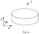
- FIGs 1a , 1b , 1c and 1d a printing method according to an exemplary embodiment of the present invention is schematically illustrated.
- the present invention refers to a method for printing a three-dimensional optical component 1, in particular an ophthalmic lens.
- the optical component 1 is illustrated in Figure 1a .
- the intended three-dimensional shape 2 of the optical component 1 is virtually sliced into two-dimensional slices 3 of a height h, resulting in an approximate shape 4, see the sectional view of Figure 1a .
- Figure 1b shows a sectional view of the optical component 1 in the x-z-plane.
- Each slice is defined by its height h and its base area, wherein the height h preferably is the extension of a slice 3 along the z-direction and the base area its extension in the x-y-plane.
- the slices 3 are preferably cylinders of height h.
- the radii of these cylinders differ for each slice 3 such that a best approximation to the intended shape 4 is achieved. It is clear that the quality of the approximation is defined be the height h of the slicing. The smaller h, i.e. the thinner the slices 3, the better the approximation. The height h cannot be chosen arbitrarily small.
- the height h is limited by the available and printable droplet volume. This in turn is defined through the ejection nozzles of the print head in use and additionally limited through physical constraints such as properties of the used printing ink and flight properties of the droplets. Additionally, a smaller height h, i.e. thinner slices 3, increases the printing time, making the print less efficient.
- the methods according to the present invention overcome these difficulties by providing a printing method, wherein the balance between printing speed and printing accuracy can be adjusted.
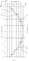
- the difference between the intended shape 2 and the approximate shape 4 is quantified.
- the difference between the intended shape 2 and the approximate shape 4 is quantified through the approximation error e, see Figure 1c .
- the difference between the intended shape 2 and the approximate shape 4 is determined for multiple, particularly preferably all, slices 3 obtained through the virtual slicing.
- the approximation error e is e.g. calculated as the difference between intended shape 2 and approximate shape 4 for each point of the base area of that slice 3, i.e.
- the approximation error e alternatively comprises a single value, e.g.
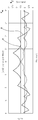
- the approximation is particularly pronounced in the vicinity and at the optical center of the optical component 1 and at the edges 10 of the slices 3.
- the layer corresponding to at least one slice 3 is printed in multi-pass mode, i.e. the at least one slice 3 is divided into multiple sub-slices 5 and their corresponding sublayers are printed in consecutive sublayer printing steps.
- an error threshold is defined and the at least one slice 3 is selected depending on the approximation error e as the slice 3 wherein the approximation error or its absolute value exceeds a defined error threshold.
- the error threshold advantageously allows the definition of a desired balance between speed and accuracy.
- the number of sub-slices 5 and the height of the respective sub-slices 5 are chosen such that the absolute value of the approximation error e of the at least one slice 3 is reduced, see the improved approximation error e in Figure 1c .
- the height of the sub-slices 5 does not increase from the first printed sub-slice 5 to the last printed sub-slice 5, i.e. the height of two sub-slices 5 printed consecutively decreases or is the same.
- the first sub-slice 5' is a cylinder of height h 1 and radius r 1 .
- the left panel of Figure 1d depicts the original slicing.
- the slicing according to a preferred embodiment of the present invention is shown in the right panel of Figure 1d .
- the height of the sub-slices 5', 5", 5"' is preferably converted into a volume of printing ink deposited when printing the respective sub-layer.
- the volume of deposited printing ink is determined through the density of deposited droplets.
- the density of deposited droplets is 66%, 33% and 33% of the density used for printing the regular slices 3 of height h, respectively for the first, second and third sublayer of the example of Figure 1d .
- the printing patterns of the multi-pass slice are, for example, randomly generated.
- the printing pattern for each sub-slice 5', 5", 5'" comprises a grid wherein each grid cell corresponds to a voxel, i.e.
- Grid cells are color coded to contain information about whether a droplet of printing ink is to be deposited at the corresponding voxel.
- the grid cells are either black or white, wherein black grid cells correspond to voxels of the sub-slice 5', 5", 5'" on which a droplet of printing ink is to be deposited during sub-slice printing and white grid cells correspond to voxels on which no printing ink is to be deposited during sub-slice printing.
- the printing patterns of the sub-slice 5', 5", 5'" are generated through conversion of a greyscale image into a black-and-white pattern, e.g. through halftoning.
- random generation of the sub-slice printing pattern comprises a step of converting a greyscale image to a black-and-white pattern using any of the known algorithms for this conversion.
- the conversion of the greyscale image into a black-and-white pattern is preferably carried out through halftoning.
- Halftoning comprises a simulation of the continuous greyscale image through a pattern of black dots of either varying size and/or spacing on a white background. Additionally, a slice offset is preferably added to the slicing.
- the slice offset constitutes an additional parameter with respect to which the approximation can be improved.
- the slice offset is chosen such that the absolute value of the approximation error e is reduced.
- the at least one multi-pass layer is pin cured with a reduced pinning intensity as compared to the layers which are not printed in multi-pass mode. For example, the at least one layer is printed with 15% pinning intensity.
- a printing method according to an exemplary embodiment of the present invention is schematically illustrated.
- the printing pattern 6 is adjusted such that the adjusted printing pattern 7 comprises a first sub-pattern 8 determining volume elements at which droplets of a first volume are to be deposited and a second sub-pattern 9 determining volume elements at which droplets of a second volume are to be deposited, wherein the first volume is larger than the second volume, see Figure 2a .
- Adjusting the printing pattern 6 of the at least one slice 3 such that the adjusted printing pattern 7 comprises a first and a second sub-pattern 8, 9, respectively, advantageously increases the flexibility of the approximation, resulting in an optical component 1 of increased optical quality.
- the first and the second sub-pattern 8, 9 droplets of a first and second volume are deposited on a first and a second region of the layer corresponding to the at least one slice 3. Due to the differing volume of the deposited droplets, the first and the second region preferably exhibit a first and a second height. It is preferred that the height of the first region comprising the droplets of the first volume is larger than the height of the second region comprising the droplets of the second volume.
- the first and second sub-pattern 8, 9 are adjusted such that the absolute value of the approximation error e of the at least one slice 3 is reduced through the adjustment of the printing pattern 6.
- the second sub-pattern 9 comprises the edges 10 of the at least one slice 3.
- a lower volume of printing ink is preferably deposited. In this way, additional steps can be provided, improving the approximation to the intended shape 4.
- the first sub-pattern 8 comprises a black pattern and the second sub-pattern 9 comprises a greyscale pattern, wherein black pixels refer to volume elements on which droplets of the first volume are deposited, grey pixels of the pattern refer to volume elements on which droplets of the second volume are deposited and white pixels refer to volume elements on which no droplets are deposited.
- black pixels refer to volume elements on which droplets of the first volume are deposited
- grey pixels of the pattern refer to volume elements on which droplets of the second volume are deposited
- white pixels refer to volume elements on which no droplets are deposited.
- the printing pattern 6 is adjusted such that the adjusted printing pattern 7 comprises a first sub-pattern 8 and a second sub-pattern 9, wherein the first sub-pattern 8 corresponds to a first density of deposited droplets and the second sub-pattern 9 corresponds to a second density of deposited droplets, wherein the first density is higher than the second density, see Figure 2b .
- the adjustment of the printing pattern advantageously increases the flexibility and hence accuracy of the approximation, resulting in an optical component 1 of increased quality.
- the first and second sub-patterns 8, 9 are adjusted such that the absolute value of the approximation error e of the at least one slice 3 is reduced through the adjustment of the printing pattern 6.
- the first and second sub-patterns 8, 9 of a first and second density of deposited droplets correspond to first and second regions of the corresponding layer with a first and second height, respectively.
- the first height is larger than the second height.
- the second sub-pattern 9 comprises the edges 10 of the at least one slice 3.
- the printing pattern 7 comprises a black-and-white pattern, wherein black pixels correspond to volume elements on which droplets of printing ink are to be deposited and white pixels correspond to volume elements on which no droplets of printing ink are to be deposited and wherein the first sub-pattern 8 comprises a first density of black pixels and the second sub-pattern 9 comprises the second density of black pixels.
- the first sub-pattern 8 comprises only black pixels and the second sub-pattern 9 comprises a checkerboard pattern. In this way, a first region of the corresponding layer of height h and a second region of a height h 2 ⁇ h are provided. This is particularly beneficial when printing optical components 1 with convex sections.
- the second sub-pattern 9 is dithered.
- the second sub-pattern 9 is e.g. obtained from a greyscale image through dithering.
- the layer corresponding to the at least one slice 3 is pin cured with an adjusted pinning energy, wherein the pinning energy allows a smooth transition of the deposited droplets.
- a slice offset is preferably added to the slicing.
- the slice offset constitutes an additional parameter with respect to which the approximation can be improved.
- the slice offset is chosen such that the absolute value of the approximation error e is reduced.
Landscapes
- Engineering & Computer Science (AREA)
- Chemical & Material Sciences (AREA)
- Manufacturing & Machinery (AREA)
- Materials Engineering (AREA)
- Mechanical Engineering (AREA)
- Health & Medical Sciences (AREA)
- Ophthalmology & Optometry (AREA)
- Physics & Mathematics (AREA)
- Optics & Photonics (AREA)
Priority Applications (1)
| Application Number | Priority Date | Filing Date | Title |
|---|---|---|---|
| EP19168736.7A EP3722073A1 (de) | 2019-04-11 | 2019-04-11 | Verfahren zum drucken einer optischen komponente |
Applications Claiming Priority (1)
| Application Number | Priority Date | Filing Date | Title |
|---|---|---|---|
| EP19168736.7A EP3722073A1 (de) | 2019-04-11 | 2019-04-11 | Verfahren zum drucken einer optischen komponente |
Publications (1)
| Publication Number | Publication Date |
|---|---|
| EP3722073A1 true EP3722073A1 (de) | 2020-10-14 |
Family
ID=66105243
Family Applications (1)
| Application Number | Title | Priority Date | Filing Date |
|---|---|---|---|
| EP19168736.7A Withdrawn EP3722073A1 (de) | 2019-04-11 | 2019-04-11 | Verfahren zum drucken einer optischen komponente |
Country Status (1)
| Country | Link |
|---|---|
| EP (1) | EP3722073A1 (de) |
Cited By (11)
| Publication number | Priority date | Publication date | Assignee | Title |
|---|---|---|---|---|
| CN113183470A (zh) * | 2021-05-12 | 2021-07-30 | 电子科技大学 | 一种保留模型非常规特征的3d打印自适应分层方法 |
| CN113334773A (zh) * | 2021-06-11 | 2021-09-03 | 电子科技大学 | 一种基于自适应分层的3d打印成型方向多目标优化方法 |
| CN113414987A (zh) * | 2021-06-23 | 2021-09-21 | 哈尔滨理工大学 | 一种3d打印自适应分层厚度方法 |
| CN115871231A (zh) * | 2022-12-16 | 2023-03-31 | 珠海赛纳三维科技有限公司 | 三维打印方法、三维打印装置及计算机设备 |
| WO2023149944A1 (en) * | 2022-02-03 | 2023-08-10 | Atheneum Optical Sciences, Llc | Polymeric additive manufacturing and ophthalmic lenses formed thereby |
| WO2023156055A1 (en) | 2022-02-18 | 2023-08-24 | Meta Platforms Technologies, Llc | Method for producing an optical structure and optical structure |
| WO2023227255A1 (en) | 2022-05-27 | 2023-11-30 | Meta Platforms Technologies, Llc | Method for producing a three-dimensional optical structure and three-dimensional optical structure |
| WO2023227254A1 (en) | 2022-05-27 | 2023-11-30 | Meta Platforms Technologies, Llc | Method for producing a three-dimensional optical structure and three-dimensional optical structure |
| EP4324630A1 (de) | 2022-08-17 | 2024-02-21 | Meta Platforms Technologies, LLC | Verfahren zur herstellung einer dreidimensionalen optischen struktur und system zur herstellung einer dreidimensionalen optischen struktur |
| US12042981B1 (en) | 2023-02-22 | 2024-07-23 | Atheneum Optical Sciences, Llc | Multifocal polymeric lenses and methods of manufacture |
| EP4574406A1 (de) * | 2023-12-20 | 2025-06-25 | Essilor International | Verfahren zur generativen fertigung einer ophthalmischen vorrichtung und fertigungssystem zur durchführung solch eines verfahrens |
Citations (8)
| Publication number | Priority date | Publication date | Assignee | Title |
|---|---|---|---|---|
| US6405095B1 (en) * | 1999-05-25 | 2002-06-11 | Nanotek Instruments, Inc. | Rapid prototyping and tooling system |
| US20040135276A1 (en) * | 2003-01-09 | 2004-07-15 | Nielsen Jeffrey A. | Methods and systems for producing an object through solid freeform fabrication |
| US20040159978A1 (en) * | 2003-01-29 | 2004-08-19 | Nielsen Jeffrey A. | Methods and systems for producing an object through solid freeform fabrication by varying a concentration of ejected material applied to an object layer |
| US20110249048A1 (en) * | 2008-12-19 | 2011-10-13 | Agfa Graphics Nv | Image processing method for three-dimensional printing |
| US20160101573A1 (en) * | 2013-06-07 | 2016-04-14 | Essilor International (Compagnie Générale d'Optique) | Process and machine for manufacturing an ophthalmic lens |
| US20170182715A1 (en) * | 2015-12-28 | 2017-06-29 | Ricoh Company, Ltd. | Stereoscopic modeling apparatus, information processing device, and production method of output object |
| US20180136632A1 (en) * | 2015-06-05 | 2018-05-17 | Canon Kabushiki Kaisha | Information processing apparatus and information processing method |
| US20180290399A1 (en) * | 2017-04-10 | 2018-10-11 | Xyzprinting, Inc. | Method of three-dimensional printing and system thereof |
-
2019
- 2019-04-11 EP EP19168736.7A patent/EP3722073A1/de not_active Withdrawn
Patent Citations (8)
| Publication number | Priority date | Publication date | Assignee | Title |
|---|---|---|---|---|
| US6405095B1 (en) * | 1999-05-25 | 2002-06-11 | Nanotek Instruments, Inc. | Rapid prototyping and tooling system |
| US20040135276A1 (en) * | 2003-01-09 | 2004-07-15 | Nielsen Jeffrey A. | Methods and systems for producing an object through solid freeform fabrication |
| US20040159978A1 (en) * | 2003-01-29 | 2004-08-19 | Nielsen Jeffrey A. | Methods and systems for producing an object through solid freeform fabrication by varying a concentration of ejected material applied to an object layer |
| US20110249048A1 (en) * | 2008-12-19 | 2011-10-13 | Agfa Graphics Nv | Image processing method for three-dimensional printing |
| US20160101573A1 (en) * | 2013-06-07 | 2016-04-14 | Essilor International (Compagnie Générale d'Optique) | Process and machine for manufacturing an ophthalmic lens |
| US20180136632A1 (en) * | 2015-06-05 | 2018-05-17 | Canon Kabushiki Kaisha | Information processing apparatus and information processing method |
| US20170182715A1 (en) * | 2015-12-28 | 2017-06-29 | Ricoh Company, Ltd. | Stereoscopic modeling apparatus, information processing device, and production method of output object |
| US20180290399A1 (en) * | 2017-04-10 | 2018-10-11 | Xyzprinting, Inc. | Method of three-dimensional printing and system thereof |
Cited By (22)
| Publication number | Priority date | Publication date | Assignee | Title |
|---|---|---|---|---|
| CN113183470A (zh) * | 2021-05-12 | 2021-07-30 | 电子科技大学 | 一种保留模型非常规特征的3d打印自适应分层方法 |
| CN113183470B (zh) * | 2021-05-12 | 2022-07-15 | 电子科技大学 | 一种保留模型非常规特征的3d打印自适应分层方法 |
| CN113334773A (zh) * | 2021-06-11 | 2021-09-03 | 电子科技大学 | 一种基于自适应分层的3d打印成型方向多目标优化方法 |
| CN113414987A (zh) * | 2021-06-23 | 2021-09-21 | 哈尔滨理工大学 | 一种3d打印自适应分层厚度方法 |
| US11874435B1 (en) | 2022-02-03 | 2024-01-16 | Atheneum Optical Sciences, Llc | Polymeric additive manufacturing of an ophthalmic lens |
| US20250028080A1 (en) * | 2022-02-03 | 2025-01-23 | Atheneum Optical Sciences, Llc | Methods of additive manufacturing of an article corresponding with an array of data values |
| US11789181B1 (en) | 2022-02-03 | 2023-10-17 | Atheneum Optical Sciences, Llc | Polymeric additive manufacturing and ophthalmic lenses formed thereby |
| US12352923B2 (en) | 2022-02-03 | 2025-07-08 | Atheneum Optical Sciences, Llc | Polymeric additive manufacturing of an ophthalmic lens |
| WO2023149944A1 (en) * | 2022-02-03 | 2023-08-10 | Atheneum Optical Sciences, Llc | Polymeric additive manufacturing and ophthalmic lenses formed thereby |
| US12320950B2 (en) * | 2022-02-03 | 2025-06-03 | Atheneum Optical Sciences, Llc | Methods of additive manufacturing of an article corresponding with an array of data values |
| US12313815B2 (en) | 2022-02-03 | 2025-05-27 | Atheneum Optical Sciences, Llc | Additive manufacturing of an optical element |
| EP4323814A1 (de) | 2022-02-03 | 2024-02-21 | Atheneum Optical Sciences, LLC | Polymeradditivherstellung und damit hergestellte ophthalmische linsen |
| EP4323814A4 (de) * | 2022-02-03 | 2025-04-16 | Atheneum Optical Sciences, LLC | Polymeradditivherstellung und damit hergestellte ophthalmische linsen |
| WO2023156055A1 (en) | 2022-02-18 | 2023-08-24 | Meta Platforms Technologies, Llc | Method for producing an optical structure and optical structure |
| WO2023227254A1 (en) | 2022-05-27 | 2023-11-30 | Meta Platforms Technologies, Llc | Method for producing a three-dimensional optical structure and three-dimensional optical structure |
| WO2023227255A1 (en) | 2022-05-27 | 2023-11-30 | Meta Platforms Technologies, Llc | Method for producing a three-dimensional optical structure and three-dimensional optical structure |
| WO2024039797A1 (en) | 2022-08-17 | 2024-02-22 | Meta Platforms Technologies, Llc | Method for producing a three-dimensional optical structure and system for producing a three-dimensional optical structure |
| EP4324630A1 (de) | 2022-08-17 | 2024-02-21 | Meta Platforms Technologies, LLC | Verfahren zur herstellung einer dreidimensionalen optischen struktur und system zur herstellung einer dreidimensionalen optischen struktur |
| CN115871231A (zh) * | 2022-12-16 | 2023-03-31 | 珠海赛纳三维科技有限公司 | 三维打印方法、三维打印装置及计算机设备 |
| US12042981B1 (en) | 2023-02-22 | 2024-07-23 | Atheneum Optical Sciences, Llc | Multifocal polymeric lenses and methods of manufacture |
| EP4574406A1 (de) * | 2023-12-20 | 2025-06-25 | Essilor International | Verfahren zur generativen fertigung einer ophthalmischen vorrichtung und fertigungssystem zur durchführung solch eines verfahrens |
| WO2025132265A1 (en) * | 2023-12-20 | 2025-06-26 | Essilor International | Method for additively manufacturing an ophthalmic device and manufacturing system configured to carry out such a method |
Similar Documents
| Publication | Publication Date | Title |
|---|---|---|
| EP3722073A1 (de) | Verfahren zum drucken einer optischen komponente | |
| US10811246B2 (en) | Forming method, forming system, and forming apparatus | |
| US11104169B2 (en) | Method and system for building painted three-dimensional objects | |
| JP6378932B2 (ja) | 三次元構造物の形成装置および形成方法 | |
| EP3121007B1 (de) | Verfahren zum drucken eines objekts mit einer oberfläche mit verschiedenen höhen | |
| US10183504B2 (en) | Image processing device, image processing system, and method of forming image | |
| WO2015163259A1 (ja) | 印刷方法及び印刷装置 | |
| JP2012254612A (ja) | 印刷装置及び印刷方法 | |
| US20180056581A1 (en) | Forming apparatus and forming method | |
| US10695974B2 (en) | Three-dimensional object shaping method and three-dimensional object shaping device | |
| JP2016137703A (ja) | 三次元造形装置、三次元造形方法、およびコンピュータープログラム | |
| WO2018079416A1 (ja) | 造形システム、造形方法、造形物の製造方法、及び造形物 | |
| JP6861087B2 (ja) | 造形装置、造形方法、及び造形システム | |
| CN105965882B (zh) | 三维造型装置及三维物体制造方法 | |
| US20250381728A1 (en) | Shaping device and shaping method | |
| HK40039386A (en) | Method for printing an optical component | |
| JP2022103448A (ja) | 造形物 | |
| US20220111610A1 (en) | Method for printing a multifocal lens | |
| JP6823435B2 (ja) | 造形装置及び造形方法 | |
| CN105965883A (zh) | 三维造型装置及三维物体制造方法 | |
| JP6559035B2 (ja) | 記録データ生成装置および記録データ生成方法 | |
| JP7473468B2 (ja) | 印刷方法 | |
| EP3927531A1 (de) | Verfahren zum drucken einer optischen komponente | |
| JP2013028024A (ja) | 印刷装置及び印刷方法 | |
| JP2021109394A (ja) | 造形装置及び造形方法 |
Legal Events
| Date | Code | Title | Description |
|---|---|---|---|
| PUAI | Public reference made under article 153(3) epc to a published international application that has entered the european phase |
Free format text: ORIGINAL CODE: 0009012 |
|
| STAA | Information on the status of an ep patent application or granted ep patent |
Free format text: STATUS: THE APPLICATION HAS BEEN PUBLISHED |
|
| AK | Designated contracting states |
Kind code of ref document: A1 Designated state(s): AL AT BE BG CH CY CZ DE DK EE ES FI FR GB GR HR HU IE IS IT LI LT LU LV MC MK MT NL NO PL PT RO RS SE SI SK SM TR |
|
| AX | Request for extension of the european patent |
Extension state: BA ME |
|
| STAA | Information on the status of an ep patent application or granted ep patent |
Free format text: STATUS: REQUEST FOR EXAMINATION WAS MADE |
|
| 17P | Request for examination filed |
Effective date: 20210408 |
|
| RBV | Designated contracting states (corrected) |
Designated state(s): AL AT BE BG CH CY CZ DE DK EE ES FI FR GB GR HR HU IE IS IT LI LT LU LV MC MK MT NL NO PL PT RO RS SE SI SK SM TR |
|
| REG | Reference to a national code |
Ref country code: HK Ref legal event code: DE Ref document number: 40039386 Country of ref document: HK |
|
| RIC1 | Information provided on ipc code assigned before grant |
Ipc: B33Y 50/00 20150101ALI20230502BHEP Ipc: B33Y 10/00 20150101ALI20230502BHEP Ipc: B29D 11/00 20060101ALI20230502BHEP Ipc: B29C 64/386 20170101ALI20230502BHEP Ipc: B29C 64/112 20170101AFI20230502BHEP |
|
| GRAJ | Information related to disapproval of communication of intention to grant by the applicant or resumption of examination proceedings by the epo deleted |
Free format text: ORIGINAL CODE: EPIDOSDIGR1 |
|
| GRAP | Despatch of communication of intention to grant a patent |
Free format text: ORIGINAL CODE: EPIDOSNIGR1 |
|
| GRAP | Despatch of communication of intention to grant a patent |
Free format text: ORIGINAL CODE: EPIDOSNIGR1 |
|
| STAA | Information on the status of an ep patent application or granted ep patent |
Free format text: STATUS: GRANT OF PATENT IS INTENDED |
|
| INTG | Intention to grant announced |
Effective date: 20230621 |
|
| STAA | Information on the status of an ep patent application or granted ep patent |
Free format text: STATUS: THE APPLICATION IS DEEMED TO BE WITHDRAWN |
|
| 18D | Application deemed to be withdrawn |
Effective date: 20231101 |