EP3722070A1 - Functional member and method for manufacturing same - Google Patents
Functional member and method for manufacturing same Download PDFInfo
- Publication number
- EP3722070A1 EP3722070A1 EP18886693.3A EP18886693A EP3722070A1 EP 3722070 A1 EP3722070 A1 EP 3722070A1 EP 18886693 A EP18886693 A EP 18886693A EP 3722070 A1 EP3722070 A1 EP 3722070A1
- Authority
- EP
- European Patent Office
- Prior art keywords
- microneedles
- functional member
- laser beam
- member according
- pitch
- Prior art date
- Legal status (The legal status is an assumption and is not a legal conclusion. Google has not performed a legal analysis and makes no representation as to the accuracy of the status listed.)
- Withdrawn
Links
Images




Classifications
-
- B—PERFORMING OPERATIONS; TRANSPORTING
- B23—MACHINE TOOLS; METAL-WORKING NOT OTHERWISE PROVIDED FOR
- B23K—SOLDERING OR UNSOLDERING; WELDING; CLADDING OR PLATING BY SOLDERING OR WELDING; CUTTING BY APPLYING HEAT LOCALLY, e.g. FLAME CUTTING; WORKING BY LASER BEAM
- B23K26/00—Working by laser beam, e.g. welding, cutting or boring
- B23K26/02—Positioning or observing the workpiece, e.g. with respect to the point of impact; Aligning, aiming or focusing the laser beam
- B23K26/06—Shaping the laser beam, e.g. by masks or multi-focusing
- B23K26/062—Shaping the laser beam, e.g. by masks or multi-focusing by direct control of the laser beam
- B23K26/0622—Shaping the laser beam, e.g. by masks or multi-focusing by direct control of the laser beam by shaping pulses
- B23K26/0624—Shaping the laser beam, e.g. by masks or multi-focusing by direct control of the laser beam by shaping pulses using ultrashort pulses, i.e. pulses of 1 ns or less
-
- A—HUMAN NECESSITIES
- A61—MEDICAL OR VETERINARY SCIENCE; HYGIENE
- A61K—PREPARATIONS FOR MEDICAL, DENTAL OR TOILETRY PURPOSES
- A61K9/00—Medicinal preparations characterised by special physical form
- A61K9/0012—Galenical forms characterised by the site of application
- A61K9/0019—Injectable compositions; Intramuscular, intravenous, arterial, subcutaneous administration; Compositions to be administered through the skin in an invasive manner
- A61K9/0021—Intradermal administration, e.g. through microneedle arrays or needleless injectors
-
- A—HUMAN NECESSITIES
- A61—MEDICAL OR VETERINARY SCIENCE; HYGIENE
- A61K—PREPARATIONS FOR MEDICAL, DENTAL OR TOILETRY PURPOSES
- A61K9/00—Medicinal preparations characterised by special physical form
- A61K9/70—Web, sheet or filament bases ; Films; Fibres of the matrix type containing drug
- A61K9/7023—Transdermal patches and similar drug-containing composite devices, e.g. cataplasms
-
- A—HUMAN NECESSITIES
- A61—MEDICAL OR VETERINARY SCIENCE; HYGIENE
- A61M—DEVICES FOR INTRODUCING MEDIA INTO, OR ONTO, THE BODY; DEVICES FOR TRANSDUCING BODY MEDIA OR FOR TAKING MEDIA FROM THE BODY; DEVICES FOR PRODUCING OR ENDING SLEEP OR STUPOR
- A61M37/00—Other apparatus for introducing media into the body; Percutany, i.e. introducing medicines into the body by diffusion through the skin
- A61M37/0015—Other apparatus for introducing media into the body; Percutany, i.e. introducing medicines into the body by diffusion through the skin by using microneedles
-
- B—PERFORMING OPERATIONS; TRANSPORTING
- B23—MACHINE TOOLS; METAL-WORKING NOT OTHERWISE PROVIDED FOR
- B23K—SOLDERING OR UNSOLDERING; WELDING; CLADDING OR PLATING BY SOLDERING OR WELDING; CUTTING BY APPLYING HEAT LOCALLY, e.g. FLAME CUTTING; WORKING BY LASER BEAM
- B23K26/00—Working by laser beam, e.g. welding, cutting or boring
- B23K26/02—Positioning or observing the workpiece, e.g. with respect to the point of impact; Aligning, aiming or focusing the laser beam
- B23K26/06—Shaping the laser beam, e.g. by masks or multi-focusing
- B23K26/0604—Shaping the laser beam, e.g. by masks or multi-focusing by a combination of beams
-
- B—PERFORMING OPERATIONS; TRANSPORTING
- B23—MACHINE TOOLS; METAL-WORKING NOT OTHERWISE PROVIDED FOR
- B23K—SOLDERING OR UNSOLDERING; WELDING; CLADDING OR PLATING BY SOLDERING OR WELDING; CUTTING BY APPLYING HEAT LOCALLY, e.g. FLAME CUTTING; WORKING BY LASER BEAM
- B23K26/00—Working by laser beam, e.g. welding, cutting or boring
- B23K26/02—Positioning or observing the workpiece, e.g. with respect to the point of impact; Aligning, aiming or focusing the laser beam
- B23K26/06—Shaping the laser beam, e.g. by masks or multi-focusing
- B23K26/062—Shaping the laser beam, e.g. by masks or multi-focusing by direct control of the laser beam
-
- B—PERFORMING OPERATIONS; TRANSPORTING
- B23—MACHINE TOOLS; METAL-WORKING NOT OTHERWISE PROVIDED FOR
- B23K—SOLDERING OR UNSOLDERING; WELDING; CLADDING OR PLATING BY SOLDERING OR WELDING; CUTTING BY APPLYING HEAT LOCALLY, e.g. FLAME CUTTING; WORKING BY LASER BEAM
- B23K26/00—Working by laser beam, e.g. welding, cutting or boring
- B23K26/02—Positioning or observing the workpiece, e.g. with respect to the point of impact; Aligning, aiming or focusing the laser beam
- B23K26/06—Shaping the laser beam, e.g. by masks or multi-focusing
- B23K26/064—Shaping the laser beam, e.g. by masks or multi-focusing by means of optical elements, e.g. lenses, mirrors or prisms
- B23K26/0652—Shaping the laser beam, e.g. by masks or multi-focusing by means of optical elements, e.g. lenses, mirrors or prisms comprising prisms
-
- B—PERFORMING OPERATIONS; TRANSPORTING
- B23—MACHINE TOOLS; METAL-WORKING NOT OTHERWISE PROVIDED FOR
- B23K—SOLDERING OR UNSOLDERING; WELDING; CLADDING OR PLATING BY SOLDERING OR WELDING; CUTTING BY APPLYING HEAT LOCALLY, e.g. FLAME CUTTING; WORKING BY LASER BEAM
- B23K26/00—Working by laser beam, e.g. welding, cutting or boring
- B23K26/02—Positioning or observing the workpiece, e.g. with respect to the point of impact; Aligning, aiming or focusing the laser beam
- B23K26/06—Shaping the laser beam, e.g. by masks or multi-focusing
- B23K26/067—Dividing the beam into multiple beams, e.g. multi-focusing
- B23K26/0676—Dividing the beam into multiple beams, e.g. multi-focusing into dependently operating sub-beams, e.g. an array of spots with fixed spatial relationship or for performing simultaneously identical operations
-
- B—PERFORMING OPERATIONS; TRANSPORTING
- B23—MACHINE TOOLS; METAL-WORKING NOT OTHERWISE PROVIDED FOR
- B23K—SOLDERING OR UNSOLDERING; WELDING; CLADDING OR PLATING BY SOLDERING OR WELDING; CUTTING BY APPLYING HEAT LOCALLY, e.g. FLAME CUTTING; WORKING BY LASER BEAM
- B23K26/00—Working by laser beam, e.g. welding, cutting or boring
- B23K26/08—Devices involving relative movement between laser beam and workpiece
- B23K26/082—Scanning systems, i.e. devices involving movement of the laser beam relative to the laser head
-
- B—PERFORMING OPERATIONS; TRANSPORTING
- B23—MACHINE TOOLS; METAL-WORKING NOT OTHERWISE PROVIDED FOR
- B23K—SOLDERING OR UNSOLDERING; WELDING; CLADDING OR PLATING BY SOLDERING OR WELDING; CUTTING BY APPLYING HEAT LOCALLY, e.g. FLAME CUTTING; WORKING BY LASER BEAM
- B23K26/00—Working by laser beam, e.g. welding, cutting or boring
- B23K26/12—Working by laser beam, e.g. welding, cutting or boring in a special environment or atmosphere, e.g. in an enclosure
-
- B—PERFORMING OPERATIONS; TRANSPORTING
- B23—MACHINE TOOLS; METAL-WORKING NOT OTHERWISE PROVIDED FOR
- B23K—SOLDERING OR UNSOLDERING; WELDING; CLADDING OR PLATING BY SOLDERING OR WELDING; CUTTING BY APPLYING HEAT LOCALLY, e.g. FLAME CUTTING; WORKING BY LASER BEAM
- B23K26/00—Working by laser beam, e.g. welding, cutting or boring
- B23K26/36—Removing material
- B23K26/362—Laser etching
- B23K26/364—Laser etching for making a groove or trench, e.g. for scribing a break initiation groove
-
- B—PERFORMING OPERATIONS; TRANSPORTING
- B23—MACHINE TOOLS; METAL-WORKING NOT OTHERWISE PROVIDED FOR
- B23K—SOLDERING OR UNSOLDERING; WELDING; CLADDING OR PLATING BY SOLDERING OR WELDING; CUTTING BY APPLYING HEAT LOCALLY, e.g. FLAME CUTTING; WORKING BY LASER BEAM
- B23K26/00—Working by laser beam, e.g. welding, cutting or boring
- B23K26/36—Removing material
- B23K26/38—Removing material by boring or cutting
- B23K26/382—Removing material by boring or cutting by boring
- B23K26/386—Removing material by boring or cutting by boring of blind holes
-
- B—PERFORMING OPERATIONS; TRANSPORTING
- B23—MACHINE TOOLS; METAL-WORKING NOT OTHERWISE PROVIDED FOR
- B23K—SOLDERING OR UNSOLDERING; WELDING; CLADDING OR PLATING BY SOLDERING OR WELDING; CUTTING BY APPLYING HEAT LOCALLY, e.g. FLAME CUTTING; WORKING BY LASER BEAM
- B23K26/00—Working by laser beam, e.g. welding, cutting or boring
- B23K26/36—Removing material
- B23K26/38—Removing material by boring or cutting
- B23K26/382—Removing material by boring or cutting by boring
- B23K26/389—Removing material by boring or cutting by boring of fluid openings, e.g. nozzles, jets
-
- B—PERFORMING OPERATIONS; TRANSPORTING
- B23—MACHINE TOOLS; METAL-WORKING NOT OTHERWISE PROVIDED FOR
- B23K—SOLDERING OR UNSOLDERING; WELDING; CLADDING OR PLATING BY SOLDERING OR WELDING; CUTTING BY APPLYING HEAT LOCALLY, e.g. FLAME CUTTING; WORKING BY LASER BEAM
- B23K26/00—Working by laser beam, e.g. welding, cutting or boring
- B23K26/36—Removing material
- B23K26/40—Removing material taking account of the properties of the material involved
-
- B—PERFORMING OPERATIONS; TRANSPORTING
- B23—MACHINE TOOLS; METAL-WORKING NOT OTHERWISE PROVIDED FOR
- B23K—SOLDERING OR UNSOLDERING; WELDING; CLADDING OR PLATING BY SOLDERING OR WELDING; CUTTING BY APPLYING HEAT LOCALLY, e.g. FLAME CUTTING; WORKING BY LASER BEAM
- B23K26/00—Working by laser beam, e.g. welding, cutting or boring
- B23K26/36—Removing material
- B23K26/40—Removing material taking account of the properties of the material involved
- B23K26/402—Removing material taking account of the properties of the material involved involving non-metallic material, e.g. isolators
-
- B—PERFORMING OPERATIONS; TRANSPORTING
- B29—WORKING OF PLASTICS; WORKING OF SUBSTANCES IN A PLASTIC STATE IN GENERAL
- B29C—SHAPING OR JOINING OF PLASTICS; SHAPING OF MATERIAL IN A PLASTIC STATE, NOT OTHERWISE PROVIDED FOR; AFTER-TREATMENT OF THE SHAPED PRODUCTS, e.g. REPAIRING
- B29C33/00—Moulds or cores; Details thereof or accessories therefor
- B29C33/38—Moulds or cores; Details thereof or accessories therefor characterised by the material or the manufacturing process
- B29C33/3842—Manufacturing moulds, e.g. shaping the mould surface by machining
-
- B—PERFORMING OPERATIONS; TRANSPORTING
- B29—WORKING OF PLASTICS; WORKING OF SUBSTANCES IN A PLASTIC STATE IN GENERAL
- B29C—SHAPING OR JOINING OF PLASTICS; SHAPING OF MATERIAL IN A PLASTIC STATE, NOT OTHERWISE PROVIDED FOR; AFTER-TREATMENT OF THE SHAPED PRODUCTS, e.g. REPAIRING
- B29C41/00—Shaping by coating a mould, core or other substrate, i.e. by depositing material and stripping-off the shaped article; Apparatus therefor
- B29C41/02—Shaping by coating a mould, core or other substrate, i.e. by depositing material and stripping-off the shaped article; Apparatus therefor for making articles of definite length, i.e. discrete articles
-
- A—HUMAN NECESSITIES
- A61—MEDICAL OR VETERINARY SCIENCE; HYGIENE
- A61M—DEVICES FOR INTRODUCING MEDIA INTO, OR ONTO, THE BODY; DEVICES FOR TRANSDUCING BODY MEDIA OR FOR TAKING MEDIA FROM THE BODY; DEVICES FOR PRODUCING OR ENDING SLEEP OR STUPOR
- A61M37/00—Other apparatus for introducing media into the body; Percutany, i.e. introducing medicines into the body by diffusion through the skin
- A61M37/0015—Other apparatus for introducing media into the body; Percutany, i.e. introducing medicines into the body by diffusion through the skin by using microneedles
- A61M2037/0023—Drug applicators using microneedles
-
- A—HUMAN NECESSITIES
- A61—MEDICAL OR VETERINARY SCIENCE; HYGIENE
- A61M—DEVICES FOR INTRODUCING MEDIA INTO, OR ONTO, THE BODY; DEVICES FOR TRANSDUCING BODY MEDIA OR FOR TAKING MEDIA FROM THE BODY; DEVICES FOR PRODUCING OR ENDING SLEEP OR STUPOR
- A61M37/00—Other apparatus for introducing media into the body; Percutany, i.e. introducing medicines into the body by diffusion through the skin
- A61M37/0015—Other apparatus for introducing media into the body; Percutany, i.e. introducing medicines into the body by diffusion through the skin by using microneedles
- A61M2037/0046—Solid microneedles
-
- A—HUMAN NECESSITIES
- A61—MEDICAL OR VETERINARY SCIENCE; HYGIENE
- A61M—DEVICES FOR INTRODUCING MEDIA INTO, OR ONTO, THE BODY; DEVICES FOR TRANSDUCING BODY MEDIA OR FOR TAKING MEDIA FROM THE BODY; DEVICES FOR PRODUCING OR ENDING SLEEP OR STUPOR
- A61M37/00—Other apparatus for introducing media into the body; Percutany, i.e. introducing medicines into the body by diffusion through the skin
- A61M37/0015—Other apparatus for introducing media into the body; Percutany, i.e. introducing medicines into the body by diffusion through the skin by using microneedles
- A61M2037/0053—Methods for producing microneedles
-
- A—HUMAN NECESSITIES
- A61—MEDICAL OR VETERINARY SCIENCE; HYGIENE
- A61M—DEVICES FOR INTRODUCING MEDIA INTO, OR ONTO, THE BODY; DEVICES FOR TRANSDUCING BODY MEDIA OR FOR TAKING MEDIA FROM THE BODY; DEVICES FOR PRODUCING OR ENDING SLEEP OR STUPOR
- A61M2207/00—Methods of manufacture, assembly or production
- A61M2207/10—Device therefor
-
- B—PERFORMING OPERATIONS; TRANSPORTING
- B29—WORKING OF PLASTICS; WORKING OF SUBSTANCES IN A PLASTIC STATE IN GENERAL
- B29L—INDEXING SCHEME ASSOCIATED WITH SUBCLASS B29C, RELATING TO PARTICULAR ARTICLES
- B29L2031/00—Other particular articles
- B29L2031/753—Medical equipment; Accessories therefor
- B29L2031/7544—Injection needles, syringes
Definitions
- the present invention relates to a functional member and a method of fabricating the functional member.
- Patent Literature 1 A method of fabricating microneedles is disclosed (Patent Literature 1), in which ablation processing is performed on a glass substrate by irradiating the glass substrate with, for example, a femtosecond laser beam to form a master mold having a plurality of needle-like depressions, and the patterns of the needle-like depressions are transferred to a resin to form a secondary mold having needle-like protrusions, and then a tertiary mold is formed to finally fabricate needles made of resin.
- Patent Literature 1 A method of fabricating microneedles is disclosed (Patent Literature 1), in which ablation processing is performed on a glass substrate by irradiating the glass substrate with, for example, a femtosecond laser beam to form a master mold having a plurality of needle-like depressions, and the patterns of the needle-like depressions are transferred to a resin to form a secondary mold having needle-like protrusions, and then a tertiary mold is formed to finally
- Patent Literature 1 Japanese Laid-open Patent Publication No. 2008-246492
- Patent Literature 1 implements femtosecond laser ablation, and thus, the size of the needle-like depressions and the resulting needles is restricted to the spot size of the femtosecond laser beam.
- molds are formed in a plurality of processes before a final product is produced, thereby complicating the manufacturing process.
- the present invention has been made in view of the problems above, and it is an object of the present invention to provide a functional member including a plurality of microneedles on a surface with more freedom of size, and a method of fabricating the functional member in an easier way.
- a functional member includes: a plurality of microneedles on a surface. Further, the microneedles adjacent to each other are spaced apart by a pitch ranging from 1 to 500 ⁇ m, and the microneedles have a diameter ranging from 0.25 to 250 ⁇ m and have a height ranging from 5 to 200 ⁇ m.
- a microhole is formed on the surface between the microneedles.
- the microhole has an inner diameter corresponding to the diameter of the microneedles.
- the microneedles have a bent shape.
- the microneedles have an outer shape of a substantial upright cone with a base on the surface, the substantial upright cone having a dent on a part of an outer circumferential surface.
- the microneedles have a tip having minute indentations and protrusions having a diameter equal to or smaller than 500 nm.
- the functional member is made of stainless steel or aluminum metal, or made of resin.
- the functional member is functioned as a junction member or a catalyst retaining member.
- a method of fabricating a functional member made of metal and including a plurality of microneedles on a surface includes: emitting a laser beam on a surface of a raw member and performing scanning with the laser beam in a first direction at a pitch d. Further, the microneedles are spaced apart by a pitch ranging from 1 to 500 ⁇ m, and the microneedles have a diameter ranging from 0.25 to 250 ⁇ m and have a height ranging from 5 to 200 ⁇ m, and a spot size radius of the laser beam is indicated as ⁇ , and a parameter ⁇ relative to ⁇ is set to satisfy 0 ⁇ ⁇ ⁇ 2 ⁇ , and the pitch d is set to satisfy d ⁇ 2 ⁇ + ⁇ .
- the laser beam is a subnanosecond to nanosecond pulsed laser beam.
- the surface is scanned with the laser beam only in the first direction.
- the laser beam is used for scanning only in the first direction at a scanning speed equal to or lower than 20 mm/s.
- the raw member is irradiated with the laser beam and processed in an inert gas atmosphere.
- the diameter of the microneedles is adjusted by adjusting at least one of the pitch d, the spot size radius ⁇ , the parameter ⁇ , a fluence of the laser beam or the sub-laser beams, a scanning speed, and a processing atmospheric gas.
- the method includes: preparing a functional member fabricated by the method according to any one of claims 9 to 15 as a mold; and transferring the microneedles onto a resin.
- a functional member including a plurality of microneedles on a surface with more freedom of size can be achieved more easily.
- FIG. 1 is a schematic diagram of a functional member according to an embodiment.
- This functional member 1 is made of metal.
- the functional member 1 is made of stainless steel, but the functional member 1 may be made of other types of metal such as aluminum metal.
- the shape of the functional member 1 is, but not limited to, a plate shape in the present embodiment.
- FIG. 2 is a diagram illustrating a microphotograph of the surface 1a of the functional member 1.
- FIG. 2 includes a scale for indicating the size, and the value of one division of the scale is 2.0 ⁇ m.
- the surface 1a has a plurality of microneedles 1b.
- the microneedles 1b are arranged in a plurality of rows in the direction indicated by an arrow Ar1.
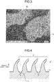
- FIG. 3 is an enlarged view of tips of the microneedles 1b.
- FIG. 3 includes a scale for indicating the size, and the value of one division of the scale is 0.5 ⁇ m. As illustrated in FIG. 3 , the tips of the microneedles 1b have minute indentations and protrusions having a diameter equal to or smaller than 500 nm.
- FIG. 4 is a schematic sectional view of the surface 1a and the vicinity of the surface 1a of the functional member 1.
- the microneedles 1b extend in a height direction from the surface 1a. Adjacent microneedles 1b are spaced apart by a pitch ranging from 1 to 500 ⁇ m. The pitch between the adjacent microneedles 1b is a pitch between the tips of the adjacent microneedles 1b.
- the microneedles 1b each have a diameter ranging from 0.25 to 250 ⁇ m. The diameter of the microneedles 1b is a mean value of the diameters from a diameter close to the surface 1a to a diameter at the tip of the microneedles 1b.
- the microneedles 1b When the microneedles 1b have a cross-section other than a circle, the diameter of a circle having the same area of this cross-section is used as the diameter of the cross-section.
- the microneedles 1b have a height ranging from 5 to 200 ⁇ m from the surface 1a.
- the microneedles 1b have a bent shape.
- the microneedles 1b extend from the surface 1a such that the microneedles 1b cross an imaginary straight-line 1 perpendicular to the surface 1a and extend without crossing the straight-line 1 and then cross the straight-line 1 again.
- the outer shape of the microneedles 1b is, for example, a substantial upright cone with a base on the surface 1a and having a dent on a part of the outer circumferential surface. Examples of the cone include a right circular cone and an oblique circular cone.
- a microhole 1c is formed on the surface 1a between the microneedles 1b (see FIG. 2 ).
- the microhole 1c has an inner diameter corresponding to, for example, the diameter of the microneedles 1b.
- the microhole 1c is formed at substantially the middle between two adjacent microneedles 1b.
- the inner diameter of the microhole 1c is an inner diameter of the microhole 1c at the edge of the surface 1a.
- the functional member 1 includes a plurality of microneedles 1b with much freedom of size, and the microneedles 1b having various sizes are formed on the surface 1a. This structure provides a higher water repellency.
- the microneedles 1b provide increased anchoring properties and increased adhesiveness, thereby increasing bonding properties.
- the microneedles 1b provide increased catalyst absorption properties, thereby increasing catalyst retainability. In particular, since the functional member 1 has bent microneedles 1b, such microneedles 1b further increase water repellency, bonding properties, and catalyst retainability.
- a fabrication apparatus 100 for implementing this fabrication method includes a laser device 101, a galvanometer scanner 102, a diffractive optical element 103, and an f ⁇ lens 104.
- a raw member 2 is a member to be processed to fabricate the functional member 1, and is a plate member made of stainless steel.
- the laser device 101 includes a laser light source such as an optical fiber laser and emits, for example, a laser beam L that is a subnanosecond to nanosecond pulsed laser beam having a pulse width ranging from 0.1 to 999 nanoseconds.
- a laser beam L that is a subnanosecond to nanosecond pulsed laser beam having a pulse width ranging from 0.1 to 999 nanoseconds.
- Using the subnanosecond to nanosecond pulsed laser beam can increase the scanning speed (processing speed) compared to using a femtosecond pulsed laser beam. This configuration can increase manufacturability of the functional member 1.
- the galvanometer scanner 102 includes galvanometer mirrors 102a, 102b each rotated by an electric motor.
- the laser beam L emitted by the laser device 101 is reflected from the rotating galvanometer mirrors 102a, 102b to use the laser beam L for scanning.
- the diffractive optical element 103 splits the laser beam L into N sub-laser beams, where N is an integer equal to or larger than two. In this fabrication method, the diffractive optical element 103 splits the laser beam L into three sub-laser beams L1, L2, L3.
- the f ⁇ lens 104 focuses the laser beam, which is used for equiangular scanning by the galvanometer scanner 102, on a certain plane and scans the plane at an equal speed.
- the certain plane is set to be coincident with a surface 2a of the raw member 2 placed on a stage (not illustrated).
- the sub-laser beams L1, L2, L3 are emitted for scanning while being focused on the surface 2a of the raw member 2 by the f ⁇ lens 104.
- Emitting the sub-laser beams L1, L2, L3 to the surface 2a of the raw member 2 can form the microneedles 1b and the inner diameter of the microholes 1c.
- the raw member 2 which is a processing target, is irradiated with the laser beam L and processed in an inert gas atmosphere such as nitrogen or argon. This configuration prevents acceleration of process due to oxygen and can stably form the microneedles 1b and the microholes 1c.
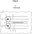
- FIG. 6 is a diagram illustrating how to form the microneedles 1b.
- the sub-laser beams L1, L2 are emitted to the surface 2a of the raw member 2, and the galvanometer scanner 102 performs scanning with the sub-laser beams L1, L2 in a first direction (indicated by an arrow Ar2) with a pitch d therebetween.
- the sub-laser beam L3 is used for scanning in the first direction with the pitch d from the sub-laser beam L2, but for ease of description, the sub-laser beam L3 is omitted from the illustration and from the description as appropriate.
- the spot size radius of respective beam spots BS1, BS2 of the sub-laser beams L1, L2 on the surface 2a be ⁇ .
- a parameter ⁇ relative to ⁇ is set to satisfy 0 ⁇ ⁇ ⁇ 2 ⁇
- the pitch d is set to satisfy d ⁇ 2 ⁇ + ⁇ . Scanning the raw member 2 with the sub-laser beams L1, L2 melts and removes the material of the raw member 2 in certain ranges from the respective centers of the beam spots BS1, BS2 of the sub-laser beams L1, L2, but the material of the raw member 2 in a region between the sub-laser beams L1, L2 remains and becomes a row of microneedles 1b.
- Another row of microneedles 1b is formed in a region between the sub-laser beams L2, L3.
- the row of microneedles 1b formed by the sub-laser beams L1, L2 and the row of microneedles 1b formed by the sub-laser beams L2, L3 are spaced apart at about the pitch d.
- the diameter of the microneedles 1b can be adjusted by adjusting at least one of the pitch d, the spot size radius ⁇ . ⁇ , the fluence of the laser beam L or the sub-laser beams L1, L2, L3, the scanning speed, and the processing atmospheric gas. It is desirable that ⁇ is set appropriately in forming the rows of microneedles 1b. It is preferred that the scanning speed has a certain low value such as 20 m/s or lower.
- the pitch d is, for example, 10 ⁇ m
- the spot size radius ⁇ is, for example, 10 ⁇ m.
- the diameter of the microneedles 1b is adjusted by adjusting the pitch d and the spot size radius ⁇ .
- the sub-laser beams L1, L2, L3 are used for scanning in the first direction from a first end of a range to be formed with the microneedles 1b to a second end opposite to the first end, at which the first scan ends and then the process proceeds to the second scan.
- the sub-laser beams L1, L2, L3 are used for scanning from an irradiation start position at the first end. This irradiation start position is shifted from the irradiation position of the first scan in a direction orthogonal to the first direction, and the sub-laser beams L1, L2, L3 are used for scanning in the first direction.
- the sub-laser beams L1, L2, L3 are used for scanning only in the first direction in the same manner as described above, and many microneedles 1b are formed in a desirable range.
- the functional member 1 can be fabricated in this manner.
- the process of splitting the laser beam L into the sub-laser beams L1, L2, L3 and performing scanning with the sub-laser beams to form the microneedles 1b can reduce the takt time to about one-third compared to the takt time of a case using the laser beam L to form the microneedles 1b.
- FIG. 7 is a diagram illustrating an example scanning pattern of the sub-laser beams L1, L2, L3.
- FIG. 7 illustrates a scanning pattern seen in a direction perpendicular to the surface 2a of the raw member 2.
- N is three in FIG. 7 .
- the sub-laser beams L1, L2, L3 are used for scanning at the equal pitch d.
- FIG. 8 is a diagram illustrating another example scanning pattern of the sub-laser beams L1, L2, L3.
- FIG. 8 illustrates a scanning pattern seen in a direction perpendicular to the surface 2a of the raw member 2.
- N is three in FIG. 8 .
- the pitch I in this case corresponds to the pitch d.
- N is three in FIGS. 7 and 8 .
- the takt time can be reduced to, for example, about one-Nth.
- Using the functional member 1 fabricated by the fabrication method described above as a mold and transferring the microneedles 1b onto resin can fabricate a resin functional member including a plurality of microneedles on a surface.
- FIG. 9 is a diagram illustrating an example method of fabricating a functional member made of resin.
- the functional member 1 including a plurality of microneedles 1b on the surface 1a is prepared as a mold and a resin 3 such as thermosetting resin is applied to the surface 1a, and the resin 3 is cured and then removed from the functional member 1.
- a functional member 4 made of resin having a plurality of microholes 4b on a surface 4a is fabricated.
- the microholes 4b have a shape transferred from the shape of the microneedles 1b.
- the functional member 4 is used as a mold and a resin 5 such as thermosetting resin is applied to the surface 4a, and the resin 5 is cured and then removed from the functional member 4.
- a functional member 6 made of resin including a plurality of microneedles 6b on a surface 6a is fabricated.
- the microholes 6b have a shape transferred from the shape of the microneedles 1b of the functional member 1.
- the functional member and the method of fabricating the functional member according to the present invention are suitable for use in various applications using, for example, water repellent properties of the functional member and for use in medical nanopatches.
Landscapes
- Engineering & Computer Science (AREA)
- Physics & Mathematics (AREA)
- Optics & Photonics (AREA)
- Health & Medical Sciences (AREA)
- Mechanical Engineering (AREA)
- Plasma & Fusion (AREA)
- Dermatology (AREA)
- Life Sciences & Earth Sciences (AREA)
- Animal Behavior & Ethology (AREA)
- Veterinary Medicine (AREA)
- Public Health (AREA)
- General Health & Medical Sciences (AREA)
- Medical Informatics (AREA)
- Anesthesiology (AREA)
- Hematology (AREA)
- Heart & Thoracic Surgery (AREA)
- Biomedical Technology (AREA)
- Medicinal Chemistry (AREA)
- Chemical & Material Sciences (AREA)
- Pharmacology & Pharmacy (AREA)
- Epidemiology (AREA)
- Bioinformatics & Cheminformatics (AREA)
- Manufacturing & Machinery (AREA)
- Media Introduction/Drainage Providing Device (AREA)
- Micromachines (AREA)
- Laser Beam Processing (AREA)
- Shaping Of Tube Ends By Bending Or Straightening (AREA)
Abstract
Description
- The present invention relates to a functional member and a method of fabricating the functional member. Background
- Studies have been made on functional members including a plurality of microneedles that are tiny needle-like protrusions formed on a surface of the functional members for use in various applications making use of, for example, the water repellent properties on the surface and for use in medical nanopatches. A method of fabricating microneedles is disclosed (Patent Literature 1), in which ablation processing is performed on a glass substrate by irradiating the glass substrate with, for example, a femtosecond laser beam to form a master mold having a plurality of needle-like depressions, and the patterns of the needle-like depressions are transferred to a resin to form a secondary mold having needle-like protrusions, and then a tertiary mold is formed to finally fabricate needles made of resin.
- Patent Literature 1: Japanese Laid-open Patent Publication No.
2008-246492 - The method disclosed in
Patent Literature 1 implements femtosecond laser ablation, and thus, the size of the needle-like depressions and the resulting needles is restricted to the spot size of the femtosecond laser beam. In addition, molds are formed in a plurality of processes before a final product is produced, thereby complicating the manufacturing process. - The present invention has been made in view of the problems above, and it is an object of the present invention to provide a functional member including a plurality of microneedles on a surface with more freedom of size, and a method of fabricating the functional member in an easier way.
- A functional member according to an embodiment includes: a plurality of microneedles on a surface. Further, the microneedles adjacent to each other are spaced apart by a pitch ranging from 1 to 500 µm, and the microneedles have a diameter ranging from 0.25 to 250 µm and have a height ranging from 5 to 200 µm.
- In the functional member according to an embodiment, a microhole is formed on the surface between the microneedles.
- In the functional member according to an embodiment, the microhole has an inner diameter corresponding to the diameter of the microneedles.
- In the functional member according to an embodiment, the microneedles have a bent shape.
- In the functional member according to an embodiment, the microneedles have an outer shape of a substantial upright cone with a base on the surface, the substantial upright cone having a dent on a part of an outer circumferential surface.
- In the functional member according to an embodiment, the microneedles have a tip having minute indentations and protrusions having a diameter equal to or smaller than 500 nm.
- In the functional member according to an embodiment, the functional member is made of stainless steel or aluminum metal, or made of resin.
- In the functional member according to an embodiment, the functional member is functioned as a junction member or a catalyst retaining member.
- A method of fabricating a functional member made of metal and including a plurality of microneedles on a surface according to an embodiment, the method includes: emitting a laser beam on a surface of a raw member and performing scanning with the laser beam in a first direction at a pitch d. Further, the microneedles are spaced apart by a pitch ranging from 1 to 500 µm, and the microneedles have a diameter ranging from 0.25 to 250 µm and have a height ranging from 5 to 200 µm, and a spot size radius of the laser beam is indicated as ω, and a parameter Δ relative to ω is set to satisfy 0 < Δ < 2ω, and the pitch d is set to satisfy d < 2ω + Δ.
- In the method of fabricating the functional member according to according to an embodiment, the laser beam is a subnanosecond to nanosecond pulsed laser beam.
- In the method of fabricating the functional member according to according to an embodiment, the surface is scanned with the laser beam only in the first direction.
- In the method of fabricating a functional member according to according to an embodiment, the laser beam is used for scanning only in the first direction at a scanning speed equal to or lower than 20 mm/s.
- In the method of fabricating the functional member according to according to an embodiment, when the laser beam is split into N sub-laser beams spaced apart at a pitch D, where N is an integer equal to or larger than two, and emitted to the surface, and when a certain sub-laser beam of the N sub-laser beams is used for scanning at a scan pitch I, I = N * D or I = 1/N * D is satisfied.
- In the method of fabricating the functional member according to according to an embodiment, the raw member is irradiated with the laser beam and processed in an inert gas atmosphere.
- In the method of fabricating the functional member according to according to an embodiment, the diameter of the microneedles is adjusted by adjusting at least one of the pitch d, the spot size radius ω, the parameter Δ, a fluence of the laser beam or the sub-laser beams, a scanning speed, and a processing atmospheric gas.
- In a method of fabricating a functional member according to an embodiment made of resin and including a plurality of microneedles on a surface, the method includes: preparing a functional member fabricated by the method according to any one of claims 9 to 15 as a mold; and transferring the microneedles onto a resin. Advantageous Effects of Invention
- According to the present invention, a functional member including a plurality of microneedles on a surface with more freedom of size can be achieved more easily. Brief Description of Drawings
-
-
FIG. 1 is a schematic diagram of a functional member according to an embodiment. -
FIG. 2 is a diagram illustrating a microphotograph of a surface of the functional member illustrated inFIG. 1 . -
FIG. 3 is an enlarged view of tips of microneedles illustrated inFIG. 2 . -
FIG. 4 is a schematic sectional view of a surface and the vicinity of the surface of the functional member illustrated inFIG. 1 . -
FIG. 5 is a diagram illustrating an example method of fabricating the functional member illustrated inFIG. 1 . -
FIG. 6 is a diagram illustrating how to form microneedles. -
FIG. 7 is a diagram illustrating an example scanning pattern of sub-laser beams. -
FIG. 8 is a diagram illustrating another example scanning pattern of the sub-laser beams. -
FIG. 9 is a diagram illustrating an example method of fabricating a functional member made of resin. Description of Embodiment - The following describes an embodiment of the present invention with reference to the accompanying drawings. The embodiment is not intended to limit the scope of the present invention. Same reference signs are given to the same or corresponding elements in the drawings. The drawings are illustrated schematically and thus it should be noted that, for example, the relation between dimensions of the elements and the ratio of the elements may differ from the actual ones. Dimensional relation or ratio of elements may differ between the drawings.
-
FIG. 1 is a schematic diagram of a functional member according to an embodiment. Thisfunctional member 1 is made of metal. In the present embodiment, thefunctional member 1 is made of stainless steel, but thefunctional member 1 may be made of other types of metal such as aluminum metal. The shape of thefunctional member 1 is, but not limited to, a plate shape in the present embodiment. - A plurality of microneedles are formed on a
surface 1a of thefunctional member 1.FIG. 2 is a diagram illustrating a microphotograph of thesurface 1a of thefunctional member 1.FIG. 2 includes a scale for indicating the size, and the value of one division of the scale is 2.0 µm. As illustrated inFIG. 2 , thesurface 1a has a plurality ofmicroneedles 1b. Themicroneedles 1b are arranged in a plurality of rows in the direction indicated by an arrow Ar1. -
FIG. 3 is an enlarged view of tips of themicroneedles 1b.FIG. 3 includes a scale for indicating the size, and the value of one division of the scale is 0.5 µm. As illustrated inFIG. 3 , the tips of themicroneedles 1b have minute indentations and protrusions having a diameter equal to or smaller than 500 nm. -
FIG. 4 is a schematic sectional view of thesurface 1a and the vicinity of thesurface 1a of thefunctional member 1. Themicroneedles 1b extend in a height direction from thesurface 1a.Adjacent microneedles 1b are spaced apart by a pitch ranging from 1 to 500 µm. The pitch between theadjacent microneedles 1b is a pitch between the tips of theadjacent microneedles 1b. Themicroneedles 1b each have a diameter ranging from 0.25 to 250 µm. The diameter of themicroneedles 1b is a mean value of the diameters from a diameter close to thesurface 1a to a diameter at the tip of themicroneedles 1b. When themicroneedles 1b have a cross-section other than a circle, the diameter of a circle having the same area of this cross-section is used as the diameter of the cross-section. Themicroneedles 1b have a height ranging from 5 to 200 µm from thesurface 1a. - The
microneedles 1b have a bent shape. For example, themicroneedles 1b extend from thesurface 1a such that themicroneedles 1b cross an imaginary straight-line 1 perpendicular to thesurface 1a and extend without crossing the straight-line 1 and then cross the straight-line 1 again. The outer shape of themicroneedles 1b is, for example, a substantial upright cone with a base on thesurface 1a and having a dent on a part of the outer circumferential surface. Examples of the cone include a right circular cone and an oblique circular cone. - A microhole 1c is formed on the
surface 1a between themicroneedles 1b (seeFIG. 2 ). Themicrohole 1c has an inner diameter corresponding to, for example, the diameter of themicroneedles 1b. For example, themicrohole 1c is formed at substantially the middle between twoadjacent microneedles 1b. The inner diameter of themicrohole 1c is an inner diameter of the microhole 1c at the edge of thesurface 1a. - The
functional member 1 includes a plurality ofmicroneedles 1b with much freedom of size, and themicroneedles 1b having various sizes are formed on thesurface 1a. This structure provides a higher water repellency. When thefunctional member 1 is used as a junction member having a function of contacting and joining, for example, resin, themicroneedles 1b provide increased anchoring properties and increased adhesiveness, thereby increasing bonding properties. When thefunctional member 1 is used as a catalyst retention member, themicroneedles 1b provide increased catalyst absorption properties, thereby increasing catalyst retainability. In particular, since thefunctional member 1 has bentmicroneedles 1b,such microneedles 1b further increase water repellency, bonding properties, and catalyst retainability. - Described next is an example method of fabricating the
functional member 1 with reference toFIGS. 5 and6 . Afabrication apparatus 100 for implementing this fabrication method includes alaser device 101, agalvanometer scanner 102, a diffractiveoptical element 103, and anfθ lens 104. Araw member 2 is a member to be processed to fabricate thefunctional member 1, and is a plate member made of stainless steel. - The
laser device 101 includes a laser light source such as an optical fiber laser and emits, for example, a laser beam L that is a subnanosecond to nanosecond pulsed laser beam having a pulse width ranging from 0.1 to 999 nanoseconds. Using the subnanosecond to nanosecond pulsed laser beam can increase the scanning speed (processing speed) compared to using a femtosecond pulsed laser beam. This configuration can increase manufacturability of thefunctional member 1. - The
galvanometer scanner 102 includesgalvanometer mirrors laser device 101 is reflected from the rotatinggalvanometer mirrors - The diffractive
optical element 103 splits the laser beam L into N sub-laser beams, where N is an integer equal to or larger than two. In this fabrication method, the diffractiveoptical element 103 splits the laser beam L into three sub-laser beams L1, L2, L3. - The
fθ lens 104 focuses the laser beam, which is used for equiangular scanning by thegalvanometer scanner 102, on a certain plane and scans the plane at an equal speed. The certain plane is set to be coincident with asurface 2a of theraw member 2 placed on a stage (not illustrated). Thus, the sub-laser beams L1, L2, L3 are emitted for scanning while being focused on thesurface 2a of theraw member 2 by thefθ lens 104. Emitting the sub-laser beams L1, L2, L3 to thesurface 2a of theraw member 2 can form themicroneedles 1b and the inner diameter of themicroholes 1c. - In forming the
microneedles 1b and themicroholes 1c, it is preferred that theraw member 2, which is a processing target, is irradiated with the laser beam L and processed in an inert gas atmosphere such as nitrogen or argon. This configuration prevents acceleration of process due to oxygen and can stably form themicroneedles 1b and themicroholes 1c. -
FIG. 6 is a diagram illustrating how to form themicroneedles 1b. As illustrated inFIG. 6 , the sub-laser beams L1, L2 are emitted to thesurface 2a of theraw member 2, and thegalvanometer scanner 102 performs scanning with the sub-laser beams L1, L2 in a first direction (indicated by an arrow Ar2) with a pitch d therebetween. The sub-laser beam L3 is used for scanning in the first direction with the pitch d from the sub-laser beam L2, but for ease of description, the sub-laser beam L3 is omitted from the illustration and from the description as appropriate. - Let the spot size radius of respective beam spots BS1, BS2 of the sub-laser beams L1, L2 on the
surface 2a be ω. In this case, a parameter Δ relative to ω is set to satisfy 0 < Δ < 2ω, and the pitch d is set to satisfy d < 2ω + Δ. Scanning theraw member 2 with the sub-laser beams L1, L2 melts and removes the material of theraw member 2 in certain ranges from the respective centers of the beam spots BS1, BS2 of the sub-laser beams L1, L2, but the material of theraw member 2 in a region between the sub-laser beams L1, L2 remains and becomes a row ofmicroneedles 1b. In the same manner, another row ofmicroneedles 1b is formed in a region between the sub-laser beams L2, L3. The row ofmicroneedles 1b formed by the sub-laser beams L1, L2 and the row ofmicroneedles 1b formed by the sub-laser beams L2, L3 are spaced apart at about the pitch d. - The diameter of the
microneedles 1b can be adjusted by adjusting at least one of the pitch d, the spot size radius ω. Δ, the fluence of the laser beam L or the sub-laser beams L1, L2, L3, the scanning speed, and the processing atmospheric gas. It is desirable that Δ is set appropriately in forming the rows ofmicroneedles 1b. It is preferred that the scanning speed has a certain low value such as 20 m/s or lower. The pitch d is, for example, 10 µm, and the spot size radius ω is, for example, 10 µm. In particular, it is preferred that the diameter of themicroneedles 1b is adjusted by adjusting the pitch d and the spot size radius ω. - In the first scan, the sub-laser beams L1, L2, L3 are used for scanning in the first direction from a first end of a range to be formed with the
microneedles 1b to a second end opposite to the first end, at which the first scan ends and then the process proceeds to the second scan. In the second scan, the sub-laser beams L1, L2, L3 are used for scanning from an irradiation start position at the first end. This irradiation start position is shifted from the irradiation position of the first scan in a direction orthogonal to the first direction, and the sub-laser beams L1, L2, L3 are used for scanning in the first direction. In the third scan and after, the sub-laser beams L1, L2, L3 are used for scanning only in the first direction in the same manner as described above, andmany microneedles 1b are formed in a desirable range. Thefunctional member 1 can be fabricated in this manner. - The process of splitting the laser beam L into the sub-laser beams L1, L2, L3 and performing scanning with the sub-laser beams to form the
microneedles 1b can reduce the takt time to about one-third compared to the takt time of a case using the laser beam L to form themicroneedles 1b. -
FIG. 7 is a diagram illustrating an example scanning pattern of the sub-laser beams L1, L2, L3.FIG. 7 illustrates a scanning pattern seen in a direction perpendicular to thesurface 2a of theraw member 2. When the number of sub-laser beams is N and the respective N sub-laser beams are spaced apart at a pitch D, and when a certain sub-laser beam of the N sub-laser beams is used for scanning at a scan pitch I, the scanning pattern satisfies I = N * D. - Specifically, N is three in
FIG. 7 . In a first scan S1, the sub-laser beams L1, L2, L3 are used for scanning while being spaced apart at a pitch D = d. In a subsequent second scan S2, the sub-laser beam L1 in the second scan is used for scanning at a scan pitch I = 3d from the sub-laser beam L1 in the first scan. In the same manner, in a third scan S3, the sub-laser beam L1 in the third scan is used for scanning at the scan pitch I = 3d from the sub-laser beam L1 in the second scan. The sub-laser beams L2, L3 are also used for scanning at the scan pitch I = 3d. In this regard, the sub-laser beams L1, L2, L3 are used for scanning at the equal pitch d. -
FIG. 8 is a diagram illustrating another example scanning pattern of the sub-laser beams L1, L2, L3.FIG. 8 illustrates a scanning pattern seen in a direction perpendicular to thesurface 2a of theraw member 2. When the number of sub-laser beams is N and the respective N sub-laser beams are spaced apart at a pitch D, and when a certain sub-laser beam of the N sub-laser beams is used for scanning at a scan pitch I, the scanning pattern satisfies I = 1/N * D. - Specifically, N is three in
FIG. 8 . In the first scan S1, the sub-laser beams L1, L2, L3 are used for scanning while being spaced apart at a pitch D = d. In the subsequent second scan S2, the sub-laser beam L1 in the second scan is used for scanning at a scan pitch I = 1/3 * d from the sub-laser beam L1 in the first scan. In the same manner, in the third scan S3, the sub-laser beam L1 in the third scan is used for scanning at the scan pitch I = 1/3 * d from the sub-laser beam L1 in the second scan. The sub-laser beams L2, L3 are also used for scanning at the scan pitch I = 1/3 * d. In this regard, the sub-laser beams L1, L2, L3 are used for scanning at the equal pitch of I = 1/3 * d. The pitch I in this case corresponds to the pitch d. - N is three in
FIGS. 7 and 8 . When N is an integer equal to or larger than two and I = N * D or I = 1/N * D is satisfied, N sub-laser beams can be used for scanning at an equal pitch. When the laser beam L is not split into sub-laser beams, N is set to one and both I = N * D and I = 1/N * D are satisfied. In this case, the laser beam L is used for scanning at a pitch D or I. When N is equal to or larger than two, the takt time can be reduced to, for example, about one-Nth. - Using the
functional member 1 fabricated by the fabrication method described above as a mold and transferring themicroneedles 1b onto resin can fabricate a resin functional member including a plurality of microneedles on a surface. -
FIG. 9 is a diagram illustrating an example method of fabricating a functional member made of resin. First, thefunctional member 1 including a plurality ofmicroneedles 1b on thesurface 1a is prepared as a mold and aresin 3 such as thermosetting resin is applied to thesurface 1a, and theresin 3 is cured and then removed from thefunctional member 1. In this process, afunctional member 4 made of resin having a plurality ofmicroholes 4b on asurface 4a is fabricated. Themicroholes 4b have a shape transferred from the shape of themicroneedles 1b. - Subsequently, the
functional member 4 is used as a mold and aresin 5 such as thermosetting resin is applied to thesurface 4a, and theresin 5 is cured and then removed from thefunctional member 4. In this process, afunctional member 6 made of resin including a plurality ofmicroneedles 6b on asurface 6a is fabricated. Themicroholes 6b have a shape transferred from the shape of themicroneedles 1b of thefunctional member 1. - The embodiment above is not intended to limit the scope of the present invention. Combinations, as appropriate, of the constituent elements described above are also included in the scope of the present invention. Further effects and modifications can be easily derived by those skilled in the art. Accordingly, broader embodiments of the present invention are not limited to the embodiment above and various modifications may be made.
- As described above, the functional member and the method of fabricating the functional member according to the present invention are suitable for use in various applications using, for example, water repellent properties of the functional member and for use in medical nanopatches.
-
- 1, 4, 6 Functional member
- 1a, 2a, 4a, 6a Surface
- 1b, 6b Microneedle
- 1c, 4b Microhole
- 2 Raw member
- 100 Fabrication apparatus
- 101 Laser device
- 102 Galvanometer scanner
- 102a, 102b Galvanometer mirror
- 103 Diffractive optical element
- 104 fθ lens
- Ar1, Ar2 Arrow
- BS1, BS2 Beam spot
- L Laser beam
- L1, L2, L3 Sub-laser beam
- S1, S2, S3 Scan
Claims (16)
- A functional member comprising:a plurality of microneedles on a surface, whereinthe microneedles adjacent to each other are spaced apart by a pitch ranging from 1 to 500 µm, and the microneedles have a diameter ranging from 0.25 to 250 µm and have a height ranging from 5 to 200 µm.
- The functional member according to claim 1, wherein a microhole is formed on the surface between the microneedles.
- The functional member according to claim 2, wherein the microhole has an inner diameter corresponding to the diameter of the microneedles.
- The functional member according to any one of claims 1 to 3, wherein the microneedles have a bent shape.
- The functional member according to any one of claims 1 to 3, wherein the microneedles have an outer shape of a substantial upright cone with a base on the surface, the substantial upright cone having a dent on a part of an outer circumferential surface.
- The functional member according to any one of claims 1 to 5, wherein the microneedles have a tip having minute indentations and protrusions having a diameter equal to or smaller than 500 nm.
- The functional member according to any one of claims 1 to 6, wherein the functional member is made of stainless steel or aluminum metal, or made of resin.
- The functional member according to any one of claims 1 to 7, wherein the functional member is functioned as a junction member or a catalyst retaining member.
- A method of fabricating a functional member made of metal and including a plurality of microneedles on a surface, the method comprising:emitting a laser beam on a surface of a raw member and performing scanning with the laser beam in a first direction at a pitch d, whereinthe microneedles are spaced apart by a pitch ranging from 1 to 500 µm, and the microneedles have a diameter ranging from 0.25 to 250 µm and have a height ranging from 5 to 200 µm, andlet a spot size radius of the laser beam be ω, and a parameter Δ relative to ω is set to satisfy 0 < Δ < 2ω, and the pitch d is set to satisfy d < 2ω + Δ.
- The method of fabricating a functional member according to claim 9, wherein the laser beam is a subnanosecond to nanosecond pulsed laser beam.
- The method of fabricating a functional member according to claim 9 or 10, wherein the surface is scanned with the laser beam only in the first direction.
- The method of fabricating a functional member according to any one of claims 9 to 11, wherein the laser beam is used for scanning only in the first direction at a scanning speed equal to or lower than 20 mm/s.
- The method of fabricating a functional member according to any one of claims 9 to 12, wherein
when the laser beam is split into N sub-laser beams spaced apart at a pitch D, where N is an integer equal to or larger than two, and emitted to the surface, and when a certain sub-laser beam of the N sub-laser beams is used for scanning at a scan pitch I, I = N ∗ D or I = 1/N ∗ D is satisfied. - The method of fabricating a functional member according to any one of claims 9 to 13, wherein the raw member is irradiated with the laser beam and processed in an inert gas atmosphere.
- The method of fabricating a functional member according to any one of claims 9 to 14, wherein the diameter of the microneedles is adjusted by adjusting at least one of the pitch d, the spot size radius ω, the parameter Δ, a fluence of the laser beam or the sub-laser beams, a scanning speed, and a processing atmospheric gas.
- A method of fabricating a functional member made of resin and including a plurality of microneedles on a surface, the method comprising:preparing a functional member fabricated by the method according to any one of claims 9 to 15 as a mold; andtransferring the microneedles onto a resin.
Applications Claiming Priority (2)
| Application Number | Priority Date | Filing Date | Title |
|---|---|---|---|
| JP2017233102 | 2017-12-05 | ||
| PCT/JP2018/044762 WO2019111959A1 (en) | 2017-12-05 | 2018-12-05 | Functional member and method for manufacturing same |
Publications (2)
| Publication Number | Publication Date |
|---|---|
| EP3722070A1 true EP3722070A1 (en) | 2020-10-14 |
| EP3722070A4 EP3722070A4 (en) | 2021-09-08 |
Family
ID=66751611
Family Applications (1)
| Application Number | Title | Priority Date | Filing Date |
|---|---|---|---|
| EP18886693.3A Withdrawn EP3722070A4 (en) | 2017-12-05 | 2018-12-05 | Functional member and method for manufacturing same |
Country Status (5)
| Country | Link |
|---|---|
| US (1) | US20200289809A1 (en) |
| EP (1) | EP3722070A4 (en) |
| JP (1) | JPWO2019111959A1 (en) |
| CN (1) | CN111433001B (en) |
| WO (1) | WO2019111959A1 (en) |
Cited By (1)
| Publication number | Priority date | Publication date | Assignee | Title |
|---|---|---|---|---|
| CN115091665A (en) * | 2022-07-15 | 2022-09-23 | 西安交通大学 | Preparation method of myopia-preventing glasses lens mold with gradual compound eye structure |
Families Citing this family (5)
| Publication number | Priority date | Publication date | Assignee | Title |
|---|---|---|---|---|
| CN117500630A (en) * | 2021-07-08 | 2024-02-02 | 松下知识产权经营株式会社 | Laser welding device, laser welding method and manufacturing method of rotating electrical machine |
| JPWO2023281930A1 (en) * | 2021-07-08 | 2023-01-12 | ||
| KR20230102002A (en) * | 2021-12-29 | 2023-07-07 | 삼성디스플레이 주식회사 | Laser machining device |
| JP7791306B2 (en) * | 2022-03-15 | 2025-12-23 | 株式会社東芝 | Laser welding method and manufacturing method for rotating electric machine |
| GB2622416B (en) * | 2022-09-15 | 2025-04-02 | Ndm Tech Ltd | Skin preparation device |
Family Cites Families (32)
| Publication number | Priority date | Publication date | Assignee | Title |
|---|---|---|---|---|
| JP2002196347A (en) * | 1993-06-04 | 2002-07-12 | Seiko Epson Corp | Liquid crystal panel and method of manufacturing liquid crystal panel |
| BRPI0412021A (en) * | 2003-06-30 | 2006-08-15 | Alza Corp | method for coating skin piercing microprojections |
| TWI246929B (en) * | 2004-07-16 | 2006-01-11 | Ind Tech Res Inst | Microneedle array device and its fabrication method |
| JP2006341089A (en) * | 2005-05-13 | 2006-12-21 | Fujikura Ltd | Medicinal product carrying device and method of manufacturing |
| US20070078414A1 (en) * | 2005-08-05 | 2007-04-05 | Mcallister Devin V | Methods and devices for delivering agents across biological barriers |
| US20070259156A1 (en) * | 2006-05-03 | 2007-11-08 | Lucent Technologies, Inc. | Hydrophobic surfaces and fabrication process |
| JP5223218B2 (en) * | 2007-03-29 | 2013-06-26 | 凸版印刷株式会社 | Method of manufacturing needle array by femtosecond laser processing |
| CN101297989B (en) * | 2008-06-19 | 2010-06-23 | 上海交通大学 | Batch preparation of hollow micro-needle based on molding |
| WO2011005188A1 (en) * | 2009-07-10 | 2011-01-13 | Milux Holding S.A. | Hip joint device |
| CN101830428B (en) * | 2010-01-18 | 2013-05-08 | 大连理工大学 | Method for manufacturing super hydrophobic surface by microneedle array |
| CN102958556B (en) * | 2010-04-28 | 2017-02-15 | 金伯利-克拉克环球有限公司 | Nanopatterned medical device with enhanced cellular interaction |
| KR101741294B1 (en) * | 2010-05-28 | 2017-05-29 | 히사미쓰 세이야꾸 가부시키가이샤 | Device having array provided with fine protrusions |
| KR101180032B1 (en) * | 2010-07-12 | 2012-09-05 | 인싸이토(주) | Method for manufacturing Hollow Microneedle with Controlled External Appearance Characteristics |
| EP2665504A4 (en) * | 2011-01-18 | 2017-01-25 | Massachusetts Institute of Technology | Deployable barbed microneedle array and uses thereof |
| DE102011089752A1 (en) * | 2011-12-23 | 2013-06-27 | Robert Bosch Gmbh | Method of making silicon microneedle arrays with holes and microneedle array |
| WO2014077243A1 (en) * | 2012-11-13 | 2014-05-22 | 富士フイルム株式会社 | Molding mold, and manufacturing method for transdermal absorption sheet |
| DE102013004574A1 (en) * | 2013-03-11 | 2014-09-11 | Johnson & Johnson Medical Gmbh | Surgical implant |
| CN103263727B (en) * | 2013-05-22 | 2015-09-30 | 清华大学 | Metal micro-needle array, percutaneous dosing paster, micropin roller and microneedle electrodes array |
| JP6312057B2 (en) * | 2014-03-17 | 2018-04-18 | 国立大学法人東京工業大学 | Microneedle and device including the same |
| RU2627150C1 (en) * | 2014-04-30 | 2017-08-03 | Кимберли-Кларк Ворлдвайд, Инк. | Group of draped micro-needle |
| CN104307098B (en) * | 2014-11-15 | 2016-09-07 | 唐晨 | Micropin doser and manufacture method thereof |
| WO2016122821A2 (en) * | 2015-01-29 | 2016-08-04 | Imra America, Inc. | Laser-based modification of transparent materials |
| CN104844814A (en) * | 2015-05-29 | 2015-08-19 | 北京化工大学 | Microneedle template and preparation method thereof |
| JP6517126B2 (en) * | 2015-10-28 | 2019-05-22 | 富士フイルム株式会社 | Sheet manufacturing method |
| JP6634623B2 (en) * | 2015-11-27 | 2020-01-22 | ライオン株式会社 | Dissolution type microneedle preparation |
| JP7020399B2 (en) * | 2016-03-25 | 2022-02-16 | 凸版印刷株式会社 | Transdermal administration device |
| KR101719319B1 (en) * | 2016-04-05 | 2017-03-23 | 주식회사 엘지생활건강 | Micro Needle structure for efficient skin-piercing |
| EP3456373A4 (en) * | 2016-05-09 | 2019-05-22 | Think-Lands Co., Ltd. | LASER MACHINING METHOD, AND MICRO NEEDLE MANUFACTURING METHOD |
| CN105998649A (en) * | 2016-06-24 | 2016-10-12 | 凌云 | Compound traditional Chinese medicine micro needle transdermal patch for treating scapulohumeral periarthritis and preparation method |
| JP2019205484A (en) * | 2016-09-29 | 2019-12-05 | 国立大学法人東北大学 | Microneedle array and its production method |
| JP2018118466A (en) * | 2017-01-26 | 2018-08-02 | 東レ株式会社 | Mold having discrete protrusion structure |
| CN108237211B (en) * | 2017-12-29 | 2020-05-19 | 广东工业大学 | Manufacturing method of amorphous alloy microneedle |
-
2018
- 2018-12-05 CN CN201880078640.0A patent/CN111433001B/en active Active
- 2018-12-05 WO PCT/JP2018/044762 patent/WO2019111959A1/en not_active Ceased
- 2018-12-05 EP EP18886693.3A patent/EP3722070A4/en not_active Withdrawn
- 2018-12-05 JP JP2019558255A patent/JPWO2019111959A1/en active Pending
-
2020
- 2020-06-02 US US16/890,172 patent/US20200289809A1/en not_active Abandoned
Cited By (1)
| Publication number | Priority date | Publication date | Assignee | Title |
|---|---|---|---|---|
| CN115091665A (en) * | 2022-07-15 | 2022-09-23 | 西安交通大学 | Preparation method of myopia-preventing glasses lens mold with gradual compound eye structure |
Also Published As
| Publication number | Publication date |
|---|---|
| EP3722070A4 (en) | 2021-09-08 |
| US20200289809A1 (en) | 2020-09-17 |
| JPWO2019111959A1 (en) | 2020-12-17 |
| WO2019111959A1 (en) | 2019-06-13 |
| CN111433001A (en) | 2020-07-17 |
| CN111433001B (en) | 2022-03-18 |
Similar Documents
| Publication | Publication Date | Title |
|---|---|---|
| US20200289809A1 (en) | Functional member and method of fabricating the same | |
| US8173038B2 (en) | Methods and systems for forming microstructures in glass substrates | |
| JP4692717B2 (en) | Brittle material cleaving device | |
| JP5389264B2 (en) | Laser processing method | |
| CN114829054B (en) | Method for laser material processing and laser processing device | |
| US12083620B2 (en) | Laser based machining | |
| EP2463051A1 (en) | Pulse laser machining apparatus and pulse laser machining method | |
| JP2010247214A (en) | Laser processing equipment | |
| JPWO2017199784A1 (en) | Cutting method of material to be processed | |
| TW200405046A (en) | Method of severing an optical fiber using a laser beam | |
| US8767786B2 (en) | Laser processing apparatus, laser processing method, and manufacturing method of photovoltaic device | |
| JP5498852B2 (en) | Pulse laser processing apparatus, shading correction apparatus, and pulse laser processing method | |
| JP6050002B2 (en) | Laser processing method | |
| JP2016210644A (en) | Plate glass, and method of forming information display portion on plate glass | |
| JP2002217126A (en) | Laser annealing method and apparatus | |
| CN103842305B (en) | The laser processing device of glass substrate | |
| JP6759619B2 (en) | Metal mask processing method for vapor deposition and metal mask processing equipment for vapor deposition | |
| JP2014091642A (en) | Laser processing method, and manufacturing method of electronic device | |
| JP2012240107A (en) | Laser processing method | |
| JP6191646B2 (en) | Welding method | |
| JP2014091641A (en) | Laser processing method, and manufacturing method of electronic device | |
| JP2013125855A (en) | Ceramic substrate, electronic device and electronic apparatus, manufacturing method of electronic device and manufacturing method of ceramic substrate | |
| JP2008114388A (en) | Microdevice manufacturing method | |
| JP2017104875A (en) | Laser processing apparatus and laser processing method | |
| JP6887641B2 (en) | Glass slicing method |
Legal Events
| Date | Code | Title | Description |
|---|---|---|---|
| STAA | Information on the status of an ep patent application or granted ep patent |
Free format text: STATUS: THE INTERNATIONAL PUBLICATION HAS BEEN MADE |
|
| PUAI | Public reference made under article 153(3) epc to a published international application that has entered the european phase |
Free format text: ORIGINAL CODE: 0009012 |
|
| STAA | Information on the status of an ep patent application or granted ep patent |
Free format text: STATUS: REQUEST FOR EXAMINATION WAS MADE |
|
| 17P | Request for examination filed |
Effective date: 20200528 |
|
| AK | Designated contracting states |
Kind code of ref document: A1 Designated state(s): AL AT BE BG CH CY CZ DE DK EE ES FI FR GB GR HR HU IE IS IT LI LT LU LV MC MK MT NL NO PL PT RO RS SE SI SK SM TR |
|
| AX | Request for extension of the european patent |
Extension state: BA ME |
|
| DAV | Request for validation of the european patent (deleted) | ||
| DAX | Request for extension of the european patent (deleted) | ||
| A4 | Supplementary search report drawn up and despatched |
Effective date: 20210811 |
|
| RIC1 | Information provided on ipc code assigned before grant |
Ipc: B23K 26/402 20140101ALI20210805BHEP Ipc: B23K 26/40 20140101ALI20210805BHEP Ipc: B23K 26/386 20140101ALI20210805BHEP Ipc: B23K 26/364 20140101ALI20210805BHEP Ipc: B23K 26/06 20140101ALI20210805BHEP Ipc: B23K 26/0622 20140101ALI20210805BHEP Ipc: B29C 59/16 20060101ALI20210805BHEP Ipc: B23K 26/352 20140101ALI20210805BHEP Ipc: B23K 26/067 20060101ALI20210805BHEP Ipc: A61M 37/00 20060101ALI20210805BHEP Ipc: B29C 59/02 20060101AFI20210805BHEP |
|
| STAA | Information on the status of an ep patent application or granted ep patent |
Free format text: STATUS: EXAMINATION IS IN PROGRESS |
|
| 17Q | First examination report despatched |
Effective date: 20220524 |
|
| STAA | Information on the status of an ep patent application or granted ep patent |
Free format text: STATUS: THE APPLICATION HAS BEEN WITHDRAWN |
|
| 18W | Application withdrawn |
Effective date: 20220916 |