JP2017104875A - Laser processing device and laser processing method - Google Patents
Laser processing device and laser processing method Download PDFInfo
- Publication number
- JP2017104875A JP2017104875A JP2015239147A JP2015239147A JP2017104875A JP 2017104875 A JP2017104875 A JP 2017104875A JP 2015239147 A JP2015239147 A JP 2015239147A JP 2015239147 A JP2015239147 A JP 2015239147A JP 2017104875 A JP2017104875 A JP 2017104875A
- Authority
- JP
- Japan
- Prior art keywords
- laser
- laser beam
- irradiation
- scanning
- processing
- Prior art date
- Legal status (The legal status is an assumption and is not a legal conclusion. Google has not performed a legal analysis and makes no representation as to the accuracy of the status listed.)
- Pending
Links
Images


Abstract
Description
本発明は、レーザー加工装置及びレーザー加工方法に関する。 The present invention relates to a laser processing apparatus and a laser processing method.
従来、金属や樹脂を対象物としてレーザーを照射することにより、対象物に切断等の加工を施す装置や方法が知られている。 2. Description of the Related Art Conventionally, there are known apparatuses and methods for performing processing such as cutting on an object by irradiating a laser with metal or resin as the object.
このようなレーザー加工装置として、パルス状のレーザービームをワーク(対象物)に対して走査するものが提案されている(例えば、特許文献1)。特許文献1に記載されたレーザー加工装置では、光を等速で角移動させながら放射することにより、レーザービームを等速で移動させるように構成されている。
As such a laser processing apparatus, an apparatus that scans a workpiece (object) with a pulsed laser beam has been proposed (for example, Patent Document 1). The laser processing apparatus described in
このようにレーザー照射によって対象物を加工すると、対象物がレーザービームによって加熱され、熱による影響を受けてしまうことがあった。例えば対象物が金属である場合には熱によって酸化してしまったり、樹脂である場合には黒色化してしまったり、さらに対象物が薄板である場合には変形が生じてしまったりすることがあった。そこで、レーザービームのパルス幅を小さくする(例えばピコ秒やフェムト秒とする)ことにより、熱影響を低減する対応が考えられる。しかしながら、例えば高い加工速度が要求される場合や、加工に必要なエネルギーが大きい場合には、熱影響が大きくなりやすく、熱影響のさらなる低減が望まれていた。 When an object is processed by laser irradiation in this way, the object is heated by the laser beam and may be affected by heat. For example, when the object is a metal, it may be oxidized by heat, when it is a resin, it may be blackened, and when the object is a thin plate, deformation may occur. It was. Therefore, it is conceivable to reduce the thermal effect by reducing the pulse width of the laser beam (for example, picosecond or femtosecond). However, for example, when a high processing speed is required or when the energy required for processing is large, the thermal effect tends to increase, and further reduction of the thermal effect has been desired.
本発明の目的は、レーザービームの照射による対象物への熱影響を効果的に低減することができるレーザー加工装置を提供することである。 The objective of this invention is providing the laser processing apparatus which can reduce effectively the heat influence to the target object by irradiation of a laser beam.
請求項1に係る発明は、上記課題を解決するために、パルス幅が1ナノ秒以下のレーザービームを対象物に照射して該対象物を加工するレーザー加工装置であって、前記レーザービームを発生させる発生手段と、前記対象物に対して前記レーザービームを走査する走査手段と、前記走査手段を制御する制御手段と、を備え、前記制御手段は、前記レーザービームの走査速度を当該レーザービームの発振周波数と照射直径との積以上とし、前記レーザービームによる照射痕が前記対象物における所定の加工ラインの全体に亘って形成されるように、前記加工ラインに沿って前記レーザービームを走査させるレーザー走査を、前記走査手段に複数回実行させることを特徴とするレーザー加工装置である。
In order to solve the above-mentioned problem, the invention according to
本発明のレーザー加工装置によれば、レーザービームの走査速度を発振周波数と照射直径との積以上とすることで、レーザービームの照射による対象物への熱影響を効果的に低減することができる。 According to the laser processing apparatus of the present invention, by making the scanning speed of the laser beam equal to or higher than the product of the oscillation frequency and the irradiation diameter, it is possible to effectively reduce the thermal influence on the object due to the laser beam irradiation. .
以下、本発明の各実施形態を図面に基づいて説明する。尚、第2、3実施形態においては、第1実施形態で説明する構成部材と同じ構成部材及び同様な機能を有する構成部材には、第1実施形態と同じ符号を付すとともに説明を省略する。 Hereinafter, each embodiment of the present invention will be described with reference to the drawings. In the second and third embodiments, the same constituent members as those described in the first embodiment and the constituent members having the same functions are denoted by the same reference numerals as those in the first embodiment and the description thereof is omitted.
[第1実施形態]
以下、本発明の第1実施形態を図面に基づいて説明する。本実施形態のレーザー加工装置1Aは、レーザービームを対象物としてのワークWに照射してワークWを加工するものであって、図1に示すように、発生手段としてのレーザー発振器2と、走査手段3Aと、制御手段と、を備える。本実施形態において、ワークWは平面状の被加工面を有し、被加工面に沿う方向をX方向及びY方向とし、被加工面に略直交する方向をZ方向とする。
[First Embodiment]
Hereinafter, a first embodiment of the present invention will be described with reference to the drawings. A
本実施形態のレーザー加工装置1Aは、例えば、後述するような直線状の加工ラインに沿ってワークWにレーザービームを照射することにより、この加工ラインに沿ってワークWを切断するために用いられる。 1 A of laser processing apparatuses of this embodiment are used in order to cut | disconnect the workpiece | work W along this process line, for example by irradiating a workpiece | work W with a laser beam along the linear process line which is mentioned later. .
レーザー発振器2は、パルス幅が1ナノ秒以下のレーザービームを発生させるように構成され、X方向を出射方向としてレーザービームを出射する。レーザービームのパルス幅や波長、出力、ビーム径は、ワークWの材質や形状、加工の種類等に応じて適宜に設定されればよい。また、レーザー発振器2は、固体レーザーやガスレーザー等であればよく、誘導放出のための媒質は適宜なものであればよい。
The
走査手段3Aは、ポリゴンミラー(可動式の反射ミラー)31と、fθレンズ32と、ステージ33と、を備え、ワークWに対してレーザービームを走査するように構成されている。
The
ポリゴンミラー31は、レーザー発振器2とX方向に対向するとともにステージ33とZ方向に対向する位置に設けられ、複数の反射面31A〜31Fを有し、Y方向に沿った回転軸を中心に回転するように構成されている。即ち、レーザー発振器2によってX方向を進行方向として出射されたレーザービームは、ポリゴンミラー31によって等角度運動するように反射され、ステージ33に向かって進行する。
The
fθレンズ32は、ポリゴンミラー31とステージ33との間に設けられ、回転するポリゴンミラー31によって等角度運動するように反射されたレーザービームを等速直線運動に変更する。即ち、レーザー発振器2が発生したレーザービームは、X方向を走査方向としてステージ33に対して走査される。また、fθレンズ32は、ワークWに照射される際のレーザービームが適宜な照射直径を有するように集光する。
The
ステージ33は、ワークWを載置可能であるとともに、Y方向に沿って平行移動可能に構成されている。即ち、レーザー発振器2が発生したレーザービームは、ステージ33上のワークWに対して走査される。また、ステージ33を移動させることにより、ワークWのY方向におけるレーザービームの照射位置を調節可能になっている。
The
尚、走査手段3は、レーザー発振器2とポリゴンミラー31との間にビームエキスパンダーを備え、ビームエキスパンダーによって照射直径を調節する構成であってもよい。
The
制御手段は、例えばレーザー加工装置全体を制御するマイクロコンピュータのCPU(中央演算処理装置)であって、ポリゴンミラー31の回転を制御するように構成されている。
The control means is, for example, a CPU (central processing unit) of a microcomputer that controls the entire laser processing apparatus, and is configured to control the rotation of the
ここで、制御手段がポリゴンミラー31を回転させた際のレーザービームの移動について説明する。本実施形態では、ポリゴンミラー31が図1における反時計回りに回転するものとし、反射面31A〜31Fがこの順番でレーザービームを反射する。また、レーザー発振器2から見てポリゴンミラー31側(図1における左側)をX方向の一方側とし、その反対側を他方側とする。
Here, the movement of the laser beam when the control means rotates the
まず、ポリゴンミラー31における最初の反射面31Aの第1端部(反射面31F側の端部)近傍がレーザー発振器2とX方向において対向する(即ち、第1端部近傍においてレーザービームが反射される)場合、反射されたレーザービームは、Z方向からX方向一方側に傾斜した方向に進行する。ポリゴンミラー31を回転させ、反射面31Aにおけるレーザービームの反射位置が第2端部(反射面31B側の端部)側に移動すると、レーザービームの進行方向のZ方向に対する傾斜が小さくなっていき、ワークWにおける照射位置がX方向他方側に移動していく。
First, the vicinity of the first end of the first reflecting
ポリゴンミラー31の回転を続けると、レーザービームがZ方向からX方向他方側に傾斜した方向に進行するようになり、ワークWにおける照射位置がさらにX方向他方側に移動する。さらにポリゴンミラー31を回転させると、反射面31Aの第2端部近傍においてレーザービームが反射された後、次の反射面31Bの第3端部(反射面31A側の端部)近傍においてレーザービームが反射されるようになり、ワークWにおける照射位置が再びX方向一方側に戻る。
When the
上記のようにポリゴンミラー31を回転させることにより、X方向一方側から他方側に向かう方向を走査方向として、ワークWに対するレーザービームの走査(レーザー走査)が複数回実行される。このとき、ポリゴンミラー31の回転速度とレーザービームの照射位置の移動速度とが比例関係を有する。レーザービームの照射位置の移動速度を、以下では単に「レーザービームの走査速度」と呼ぶ。
By rotating the
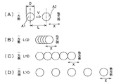
ここで、ワークWにおけるレーザービームの照射位置の詳細について説明する。レーザー発振器2はパルスレーザーを発生させる、即ち、間欠的にレーザービームを発生させるものであり、図2(A)に示すように、1のパルスによる照射痕A1に対し、次のパルスの照射痕A2はX方向他方側に位置する。このとき、レーザービームの走査速度をVとし、レーザー発振器2によるレーザービームの発振周波数をFとすると、隣り合う2つの照射痕A1、A2の照射中心間の距離Lは、L=V/Fで表される。
Here, the detail of the irradiation position of the laser beam in the workpiece | work W is demonstrated. The
距離Lがレーザービームの照射直径Dよりも小さい場合の照射痕の様子を図2(B)に示し、距離Lが照射直径Dと等しい場合の照射痕の様子を図2(C)に示し、距離Lが照射直径Dよりも大きい場合の照射痕の様子を図(D)に示す。尚、図2(B)〜(D)のそれぞれにおいて、走査速度Vは略一定であるものとする。 FIG. 2 (B) shows an irradiation mark when the distance L is smaller than the irradiation diameter D of the laser beam, and FIG. 2 (C) shows an irradiation mark when the distance L is equal to the irradiation diameter D. The state of the irradiation mark when the distance L is larger than the irradiation diameter D is shown in FIG. In each of FIGS. 2B to 2D, the scanning speed V is assumed to be substantially constant.
尚、本実施形態において、レーザー発振器2が発生するパルスレーザーの直径(光学的な直径)をビーム径とする。ビーム径は、例えばレーザービームの強度が、ガウシアンビームとして得られる空間的なパルス形状(ビームプロファイル)のピーク強度値の1/e2以上の強度を有する範囲を意味する。また、1パルスのレーザービームの照射によってワークに形成される加工痕を照射痕とし、照射痕の直径(実際に照射された直径)を照射直径Dとする。
In the present embodiment, the diameter (optical diameter) of the pulse laser generated by the
距離Lが照射直径Dよりも小さい(走査速度Vが発振周波数Fと照射直径Dとの積よりも小さい)場合、図2(B)に示すように、隣り合う照射痕同士が互いに重なる。即ち、1のパルスによって照射痕が形成された直後に、この照射痕に重なるように次のパルスによって新たな照射痕が形成される。 When the distance L is smaller than the irradiation diameter D (the scanning speed V is smaller than the product of the oscillation frequency F and the irradiation diameter D), as shown in FIG. 2B, adjacent irradiation marks overlap each other. That is, immediately after an irradiation mark is formed by one pulse, a new irradiation mark is formed by the next pulse so as to overlap this irradiation mark.
距離Lが照射直径Dと等しい(走査速度Vが発振周波数Fと照射直径Dとの積に等しい)場合、図2(C)に示すように、隣り合う照射痕の端部同士が互いに接する。また、距離Lが照射直径Dよりも大きい(走査速度Vが発振周波数Fと照射直径Dとの積よりも大きい)場合、図2(D)に示すように、隣り合う照射痕同士は互いに離隔して形成される。即ち、距離Lが照射直径D以上であれば、隣り合う照射痕同士が重ならない。 When the distance L is equal to the irradiation diameter D (the scanning speed V is equal to the product of the oscillation frequency F and the irradiation diameter D), as shown in FIG. 2C, the ends of the adjacent irradiation marks are in contact with each other. When the distance L is larger than the irradiation diameter D (the scanning speed V is larger than the product of the oscillation frequency F and the irradiation diameter D), the adjacent irradiation marks are separated from each other as shown in FIG. Formed. That is, if the distance L is equal to or greater than the irradiation diameter D, adjacent irradiation marks do not overlap.
本実施形態においては、距離Lが照射直径D以上となるように、制御手段がポリゴンミラー31を制御する。即ち、ポリゴンミラー31の回転速度が所定値以上となるようにする。以下、X方向に沿った加工ラインLNに沿ってワークWにレーザービームを照射する場合の具体的な方法(レーザー加工方法)について、図3に基づいて説明する。
In the present embodiment, the control means controls the
まず、距離Lが照射直径Dと等しくなるようにして10回のレーザー走査を繰り返した際の照射痕を図3(A)に示し、このときの各レーザー走査による照射痕を図3(B)に示す。 First, FIG. 3A shows an irradiation trace when laser scanning is repeated 10 times so that the distance L is equal to the irradiation diameter D, and the irradiation trace by each laser scanning at this time is shown in FIG. Shown in
このような例では、各レーザー走査における照射痕は、図2(C)と同様に互いに重ならず、端部同士が接する。また、1回目のレーザー走査における最初の照射痕の中心(照射中心)に対し、2回目のレーザー走査における最初の照射中心は、照射直径Dよりも小さいずれ量ΔX1だけX方向他方側に(加工ラインLNに沿って)ずれている。3回目以降のレーザー走査においても同様に、n+1回目の最初の照射中心が、n回目の最初の照射中心に対して一定のずれ量ΔX1だけX方向他方側にずれている。 In such an example, the irradiation traces in each laser scanning do not overlap each other as in FIG. In addition, the first irradiation center in the second laser scanning is smaller than the irradiation diameter D by an amount ΔX1 (on the other side in the X direction) relative to the center (irradiation center) of the first irradiation mark in the first laser scanning. Along the line LN). Similarly, in the third and subsequent laser scans, the n + 1 first irradiation center is shifted to the other side in the X direction by a fixed shift amount ΔX1 with respect to the nth first irradiation center.
また、走査速度Vが略一定であることから、n+1回目の2つ目以降の照射中心も、n回目の対応する照射中心に対してずれ量ΔX1だけX方向他方側にずれている。このようにレーザー走査を繰り返すことにより、各レーザー走査においては照射痕同士が重ならず、且つ、連続するレーザー走査における対応する照射痕同士が重なり、加工ラインLN全体に亘って照射痕が形成される。 In addition, since the scanning speed V is substantially constant, the second and subsequent irradiation centers of the (n + 1) th time are also shifted to the other side in the X direction by a shift amount ΔX1 with respect to the corresponding irradiation center of the nth time. By repeating the laser scanning in this way, the irradiation traces do not overlap each other in each laser scanning, and the corresponding irradiation traces in the continuous laser scanning overlap each other, and an irradiation trace is formed over the entire processing line LN. The
距離Lが照射直径Dよりも大きくなるようにして4回のレーザー走査を繰り返した際の照射痕を図3(C)に示し、このときの各レーザー走査による照射痕を図3(D)に示す。 FIG. 3C shows an irradiation mark when the laser scanning is repeated four times so that the distance L is larger than the irradiation diameter D. FIG. 3D shows the irradiation mark by each laser scanning at this time. Show.
次に、このような例では、各レーザー走査における照射痕は、図2(D)と同様に互いに離隔している。また、1回目のレーザー走査における最初の照射中心に対し、2回目のレーザー走査における最初の照射中心は、照射直径Dよりも小さいずれ量ΔX2だけX方向他方側に(加工ラインLNに沿って)ずれている。3回目以降のレーザー走査においても同様に、m+1回目の最初の照射中心が、m回目の最初の照射中心に対して一定のずれ量ΔX2だけX方向他方側にずれている。 Next, in such an example, the irradiation marks in each laser scanning are separated from each other as in FIG. Also, the first irradiation center in the second laser scanning is on the other side in the X direction by an amount ΔX2 smaller than the irradiation diameter D (along the processing line LN) with respect to the first irradiation center in the first laser scanning. It's off. Similarly, in the third and subsequent laser scans, the first irradiation center of the (m + 1) th time is shifted to the other side in the X direction by a certain shift amount ΔX2 with respect to the first irradiation center of the mth time.
また、走査速度Vが略一定であることから、m+1回目の2つ目以降の照射中心も、m回目の対応する照射中心に対してずれ量ΔX2だけX方向他方側にずれている。このようにレーザー走査を繰り返すことにより、各レーザー走査においては照射痕同士が重ならず、且つ、連続するレーザー走査における対応する照射痕同士が重なり、加工ラインLN全体に亘って照射痕が形成される。 Further, since the scanning speed V is substantially constant, the second and subsequent irradiation centers of the (m + 1) th time are also shifted to the other side in the X direction by a shift amount ΔX2 with respect to the corresponding irradiation center of the mth time. By repeating the laser scanning in this way, the irradiation traces do not overlap each other in each laser scanning, and the corresponding irradiation traces in the continuous laser scanning overlap each other, and an irradiation trace is formed over the entire processing line LN. The
このように、各レーザー走査における照射中心を、直前のレーザー走査における対応する照射中心に対してずらすためには、ポリゴンミラー31の各反射面31A〜31Fが径方向に対して異なる傾斜角度を有するようにすればよい。また、レーザービームを反射する反射面が切り替わる際にポリゴンミラー31の回転速度を調節することにより、照射中心をずらしてもよい。
As described above, in order to shift the irradiation center in each laser scanning with respect to the corresponding irradiation center in the immediately preceding laser scanning, the reflecting
このような本実施形態によれば、以下のような効果がある。即ち、各レーザー走査において、レーザービームの走査速度Vをレーザービームの発振周波数Fと照射直径Dとの積以上とし、照射痕同士が重ならないようにすることで、レーザービームによるワークWへの熱影響を効果的に低減することができる。 According to this embodiment, there are the following effects. That is, in each laser scanning, the laser beam scanning speed V is set to be equal to or higher than the product of the laser beam oscillation frequency F and the irradiation diameter D, so that the irradiation marks do not overlap each other. The influence can be effectively reduced.
さらに、各レーザー走査における照射中心が、直前のレーザー走査において対応する照射中心に対し、照射直径Dよりも小さいずれ量だけ加工ラインLNに沿ってずれるようにレーザービームを照射している。これにより、対応する照射痕同士を重ねることができ、適宜な回数のレーザー走査を実行することで、加工ラインLN全体に亘って照射痕を形成することができる。 Further, the laser beam is irradiated so that the irradiation center in each laser scanning is shifted along the processing line LN by an amount smaller than the irradiation diameter D with respect to the irradiation center corresponding to the immediately preceding laser scanning. Thereby, the corresponding irradiation traces can be overlapped, and the irradiation traces can be formed over the entire processing line LN by executing a suitable number of laser scans.
このように、レーザー走査を複数回実行して加工ラインLN全体に亘って照射痕を形成することで、ワークWに対し、加工ラインLNに沿った切断等の加工を施すことができる。 In this way, by performing laser scanning a plurality of times to form irradiation marks over the entire processing line LN, the workpiece W can be processed such as cutting along the processing line LN.
[第2実施形態]
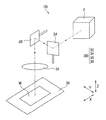
以下、本発明の第2実施形態を図面に基づいて説明する。本実施形態のレーザー加工装置1Bは、図4に示すように、レーザー発振器2と、走査手段3Bと、制御手段と、を備える。
[Second Embodiment]
Hereinafter, a second embodiment of the present invention will be described with reference to the drawings. As shown in FIG. 4, the
走査手段3Bは、可動式の反射ミラーとしての2つのガルバノミラー34、35と、fθレンズ32と、ステージ36と、を備える。
The scanning means 3B includes two galvanometer mirrors 34 and 35 as movable reflection mirrors, an
ガルバノミラー34は、レーザー発振器2と対向するとともにZ方向に沿った回動軸を中心に回動するように構成されている。即ち、レーザー発振器2によって出射されたレーザービームは、ガルバノミラー34において反射されることで、XY平面内で進行方向が変化する。
The
ガルバノミラー35は、ガルバノミラー34と対向するとともにX方向に沿った回動軸を中心に回動するように構成されている。即ち、レーザー発振器2によって出射されてガルバノミラー34によって反射されたレーザービームは、ガルバノミラー35において反射されることで、ステージ36に向かって進行する。
The
ガルバノミラー34、35を適宜に回動させることで、ステージ36のワークWに対し、XY平面内の適宜な方向を走査方向としてレーザービームを走査することができるようになっている。
By appropriately rotating the galvanometer mirrors 34 and 35, the workpiece W of the
ステージ36は、ワークWを載置可能であるとともに、三次元的に平行移動可能に構成されている。ガルバノミラー34、35によるレーザービームの走査可能領域を超えてレーザービームを走査する際には、ガルバノミラー34、35を回動させるとともにステージ36を平行移動させればよい。また、必要に応じてステージ36をZ方向に平行移動させてもよい。尚、ステージ36のみを平行移動させてレーザービームを走査してもよい。
The
本実施形態においても、第1実施形態と同様に、レーザー走査を複数回実行して加工ラインLN全体に亘って照射痕を形成し、各レーザー走査において照射痕同士が重ならないようにする。 Also in the present embodiment, similarly to the first embodiment, laser scanning is executed a plurality of times to form irradiation traces over the entire processing line LN, so that the irradiation traces do not overlap in each laser scanning.
[第3実施形態]
以下、本発明の第3実施形態を図面に基づいて説明する。本実施形態のレーザー加工装置1Cは、図5に示すように、レーザー発振器2と、走査手段3Cと、制御手段と、を備える。走査手段3Cは、fθレンズ32と、ステージ36と、を備える。
[Third Embodiment]
Hereinafter, a third embodiment of the present invention will be described with reference to the drawings. As shown in FIG. 5, the laser processing apparatus 1C of the present embodiment includes a
ステージ36は、ワークWを載置可能であるとともに、三次元的に平行移動可能に構成されている。即ち、ステージ36をXY平面に沿って平行移動させることで、XY平面内の所定の方向を走査方向としてレーザービームがワークWに対して走査されるようになっている。
The
本実施形態においても、第1実施形態と同様に、レーザー走査を複数回実行して加工ラインLN全体に亘って照射痕を形成し、各レーザー走査において照射痕同士が重ならないようにする。 Also in the present embodiment, similarly to the first embodiment, laser scanning is executed a plurality of times to form irradiation traces over the entire processing line LN, so that the irradiation traces do not overlap in each laser scanning.
ここで、レーザービームを照射してワークWを加工する具体的な条件である実施例及び比較例の加工条件について説明する。各加工条件におけるワークWの材質や寸法、及び、レーザー走査の各種パラメータについて以下に示すが、レーザー走査には上記の第1〜第3実施形態のレーザー加工装置1A〜1Cのうちいずれを用いてもよい。
Here, the processing conditions of the example and the comparative example, which are specific conditions for processing the workpiece W by irradiating the laser beam, will be described. The material and dimensions of the workpiece W under various processing conditions and various parameters of laser scanning will be described below. For the laser scanning, any of the
<実施例1、2及び比較例1〜3について>
実施例1、2及び比較例1〜3の加工条件は、パルスレーザーの照射により、ステンレス鋼で構成されたワークWの表面に直線状の溝を形成するためのものである。各加工条件は、パルス幅が100psであり、レーザービームの波長が1μmであり、発振周波数Fが1MHzであり、平均出力が10Wであり、照射直径Dが30μmであり、レーザー走査の回数が10回であることを共通とする。
<Examples 1 and 2 and Comparative Examples 1 to 3>
The processing conditions of Examples 1 and 2 and Comparative Examples 1 to 3 are for forming linear grooves on the surface of the workpiece W made of stainless steel by irradiation with a pulse laser. Each processing condition is that the pulse width is 100 ps, the wavelength of the laser beam is 1 μm, the oscillation frequency F is 1 MHz, the average output is 10 W, the irradiation diameter D is 30 μm, and the number of times of laser scanning is 10 Common times.
レーザービームの走査速度Vは、実施例1では30m/sであり、実施例2では40m/sであり、比較例1では1m/sであり、比較例2では10m/sであり、比較例3では20m/sである。即ち、隣り合う2つの照射痕の照射中心間の距離Lは、実施例1では30μmとなり、実施例2では40μmとなり、比較例1では1μmとなり、比較例2では10μmとなり、比較例3では20μmとなる。 The scanning speed V of the laser beam is 30 m / s in Example 1, 40 m / s in Example 2, 1 m / s in Comparative Example 1, 10 m / s in Comparative Example 2, and Comparative Example 3 is 20 m / s. That is, the distance L between the irradiation centers of two adjacent irradiation traces is 30 μm in Example 1, 40 μm in Example 2, 1 μm in Comparative Example 1, 10 μm in Comparative Example 2, and 20 μm in Comparative Example 3. It becomes.
尚、各レーザー走査における照射中心と、その直前のレーザー走査において対応する照射中心と、のずれ量ΔXは、照射中心間の距離Lの10分の1とする。即ち、10回のレーザー走査によって加工ライン上に均等に照射痕が形成されるようにする。 Note that a deviation amount ΔX between the irradiation center in each laser scanning and the corresponding irradiation center in the immediately preceding laser scanning is 1/10 of the distance L between the irradiation centers. That is, irradiation marks are formed uniformly on the processing line by 10 times of laser scanning.
以上のような実施例1、2及び比較例3〜5の加工条件の主要なパラメータと、加工されたワークWの状態(加工結果)と、について、以下の表1に示す。尚、加工結果の良否は金属の酸化の程度によって判断する。即ち、形成された溝の表面が金属光沢を有していれば加工結果が良好であり、酸化が進んで金属光沢が失われていれば加工結果が不良であると判断する。 Table 1 below shows the main parameters of the machining conditions of Examples 1 and 2 and Comparative Examples 3 to 5 and the state of the machined workpiece W (machining result). The quality of the processing result is judged by the degree of metal oxidation. That is, if the surface of the formed groove has a metallic luster, the processing result is good, and if the oxidation progresses and the metallic luster is lost, the processing result is judged to be bad.
照射中心間の距離Lが照射直径D以上となる、即ち、各レーザー走査において照射痕同士が重ならない実施例1、2では、加工結果が良好となった。一方、照射中心間の距離Lが照射直径D未満となる、即ち、各レーザー走査において照射痕同士が重なる比較例1〜3では、加工結果が不良となった。 In Examples 1 and 2 in which the distance L between the irradiation centers is equal to or greater than the irradiation diameter D, that is, the irradiation marks do not overlap each other in each laser scanning, the processing result is good. On the other hand, in Comparative Examples 1 to 3, in which the distance L between the irradiation centers is less than the irradiation diameter D, that is, the irradiation marks overlap each other in each laser scanning, the processing result is poor.
<実施例3〜7及び比較例4、5について>
実施例3〜7及び比較例4、5の加工条件は、パルスレーザーの照射により、ガラス繊維で強化されたエポキシ樹脂(GFRP;Glass Fiber Reinforced Plastic)で構成された厚さ100μmの薄板状のワークWを切断加工するためのものである。各加工条件は、パルス幅が10psであり、レーザービームの波長が344nmであり、発振周波数Fが50kHzであり、平均出力が4Wであり、照射直径Dが7μmであり、レーザー走査の回数が10回であることを共通とする。
<About Examples 3 to 7 and Comparative Examples 4 and 5>
The processing conditions of Examples 3 to 7 and Comparative Examples 4 and 5 were as follows: a thin plate-like workpiece having a thickness of 100 μm composed of an epoxy resin (GFRP; Glass Fiber Reinforced Plastic) reinforced with glass fiber by irradiation with a pulse laser. This is for cutting W. Each processing condition is such that the pulse width is 10 ps, the wavelength of the laser beam is 344 nm, the oscillation frequency F is 50 kHz, the average output is 4 W, the irradiation diameter D is 7 μm, and the number of times of laser scanning is 10 Common times.
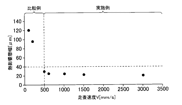
レーザービームの走査速度Vは、実施例3では500mm/sであり、実施例4では600mm/sであり、実施例5では1000mm/sであり、実施例6では1500mm/sであり、実施例7では3000mm/sであり、比較例4では100mm/sであり、比較例5では200mm/sである。 The scanning speed V of the laser beam is 500 mm / s in Example 3, 600 mm / s in Example 4, 1000 mm / s in Example 5, 1500 mm / s in Example 6, and Example 7 is 3000 mm / s, Comparative Example 4 is 100 mm / s, and Comparative Example 5 is 200 mm / s.
即ち、隣り合う2つの照射痕の照射中心間の距離Lは、実施例3では10μmとなり、実施例4では12μmとなり、実施例5では20μmとなり、実施例6では30μmとなり、実施例7では60μmとなり、比較例4では2μmとなり、比較例5では4μmとなる。従って、実施例3〜7では、L>Dとなり、比較例4、5ではL<Dとなる。 That is, the distance L between the irradiation centers of two adjacent irradiation marks is 10 μm in Example 3, 12 μm in Example 4, 20 μm in Example 5, 30 μm in Example 6, and 60 μm in Example 7. In Comparative Example 4, it is 2 μm, and in Comparative Example 5, it is 4 μm. Therefore, in Examples 3 to 7, L> D, and in Comparative Examples 4 and 5, L <D.
尚、各レーザー走査における照射中心と、その直前のレーザー走査において対応する照射中心と、のずれ量ΔXは、3.5μmとする。 Note that the deviation ΔX between the irradiation center in each laser scanning and the corresponding irradiation center in the immediately preceding laser scanning is 3.5 μm.
以上のような実施例3〜7及び比較例4、5におけるワークWの熱影響層幅と、走査速度Vと、の関係を図6に示す。尚、ワークWの熱影響層幅とは、レーザービームによって切断加工した際に、切断端面において樹脂が溶融または変色した幅のことを言う。 FIG. 6 shows the relationship between the heat-affected layer width of the workpiece W and the scanning speed V in Examples 3 to 7 and Comparative Examples 4 and 5 as described above. Note that the heat-affected layer width of the workpiece W refers to the width at which the resin is melted or discolored at the cut end face when cut by a laser beam.
L>Dとなる(各レーザー走査において照射痕同士が重ならない)実施例3〜7では、熱影響層幅が40μm以下となり、良好な結果が得られた。一方、L<Dとなる(各レーザー走査において照射痕同士が重なる)比較例4、5では、熱影響層幅が40μmよりも大きくなり、不良となった。 In Examples 3 to 7 where L> D (irradiation marks do not overlap in each laser scanning), the heat-affected layer width was 40 μm or less, and good results were obtained. On the other hand, in Comparative Examples 4 and 5 in which L <D (irradiation marks overlap each other in each laser scanning), the heat-affected layer width was larger than 40 μm, resulting in failure.
<実施例8及び比較例6について>
実施例8及び比較例6の加工条件は、パルスレーザーの照射により、炭素繊維強化プラスチック(CFRP;Carbon Fiber Reinforced Plastic)で構成された厚さ150μmの薄板状のワークWを切断加工するためのものである。各加工条件は、パルス幅が260fsであり、レーザービームの波長が1μmであり、発振周波数Fが50kHzであり、平均出力が4Wであり、照射直径Dが30μmであり、レーザー走査の回数が20回であることを共通とする。
<About Example 8 and Comparative Example 6>
The processing conditions of Example 8 and Comparative Example 6 are for cutting a thin plate-like workpiece W having a thickness of 150 μm made of carbon fiber reinforced plastic (CFRP) by irradiation with a pulsed laser. It is. Each processing condition is that the pulse width is 260 fs, the wavelength of the laser beam is 1 μm, the oscillation frequency F is 50 kHz, the average output is 4 W, the irradiation diameter D is 30 μm, and the number of times of laser scanning is 20 Common times.
レーザービームの走査速度Vは、実施例8では2000mm/sであり、比較例6では10mm/sである。即ち、隣り合う2つの照射痕の照射中心間の距離Lは、実施例8では40μmとなり、比較例6では0.2μmとなる。従って、実施例8では、L>Dとなり、比較例6ではL<Dとなる。尚、各レーザー走査における照射中心と、その直前のレーザー走査において対応する照射中心と、のずれ量ΔXは、1μmとする。 The scanning speed V of the laser beam is 2000 mm / s in Example 8, and 10 mm / s in Comparative Example 6. That is, the distance L between the irradiation centers of two adjacent irradiation marks is 40 μm in Example 8 and 0.2 μm in Comparative Example 6. Therefore, L> D in Example 8, and L <D in Comparative Example 6. Note that the amount of deviation ΔX between the irradiation center in each laser scanning and the corresponding irradiation center in the immediately preceding laser scanning is 1 μm.
L>Dとなる(各レーザー走査において照射痕同士が重ならない)実施例8では、ワークWの熱影響層幅が3μmとなった。即ち、熱影響層幅が40μm以下となり、良好な結果が得られた。一方、L<Dとなる(各レーザー走査において照射痕同士が重なる)比較例6では、熱影響層幅が100μmとなった。即ち、熱影響層幅が40μmよりも大きくなり、不良となった。 In Example 8 where L> D (irradiation marks do not overlap in each laser scanning), the heat-affected layer width of the workpiece W was 3 μm. That is, the heat-affected layer width was 40 μm or less, and good results were obtained. On the other hand, in Comparative Example 6 where L <D (irradiation marks overlap each other in each laser scanning), the heat-affected layer width was 100 μm. That is, the heat-affected layer width was larger than 40 μm, resulting in failure.
なお、本発明は、前記実施形態に限定されるものではなく、本発明の目的が達成できる他の構成等を含み、以下に示すような変形等も本発明に含まれる。 In addition, this invention is not limited to the said embodiment, Including other structures etc. which can achieve the objective of this invention, the deformation | transformation etc. which are shown below are also contained in this invention.
例えば、前記第1実施形態では、各レーザー走査における照射中心が直前のレーザー走査において対応する照射中心に対し、X方向他方側に一定のずれ量ΔX1又はΔx2だけずれるものとしたが、ずれの様態はこれに限定されない。即ち、ずれ量が一定でなくてもよいし、X方向一方側にずれるようにしてもよいし、X方向一方側へのずれと他方側へのずれとが混在していてもよい。 For example, in the first embodiment, the irradiation center in each laser scanning is shifted from the corresponding irradiation center in the immediately preceding laser scanning by a certain amount of shift ΔX1 or Δx2 on the other side in the X direction. Is not limited to this. That is, the amount of deviation may not be constant, may be shifted to one side in the X direction, or may be mixed with a shift toward one side in the X direction and a shift toward the other side.
また、実施例1〜8において、レーザービームについての種々のパラメータについて例示したが、これらのパラメータは、ワークWの種類や加工の種類に応じて適宜に設定されればよく、走査速度Vが発振周波数Fと照射直径Dとの積以上となるようにすればよい。 In the first to eighth embodiments, various parameters relating to the laser beam have been illustrated. However, these parameters may be appropriately set according to the type of workpiece W and the type of processing, and the scanning speed V oscillates. What is necessary is just to become more than the product of the frequency F and the irradiation diameter D.
その他、本発明を実施するための最良の構成、方法などは、以上の記載で開示されているが、本発明は、これに限定されるものではない。すなわち、本発明は、主に特定の実施形態に関して特に図示され、且つ、説明されているが、本発明の技術的思想および目的の範囲から逸脱することなく、以上述べた実施形態に対し、当業者が様々な変形を加えることができるものである。 In addition, the best configuration, method and the like for carrying out the present invention have been disclosed in the above description, but the present invention is not limited to this. That is, the present invention has been illustrated and described primarily with respect to particular embodiments, but the present invention is not limited to the embodiments described above without departing from the scope of the technical idea and object of the present invention. The trader can add various modifications.
従って、上記に開示した形状、材質などを限定した記載は、本発明の理解を容易にするために例示的に記載したものであり、本発明を限定するものではない。それらの形状、材質などの限定の一部、もしくは全部の限定を外した部材の名称での記載は、本発明に含まれるものである。 Therefore, the description which limited the shape, the material, etc. disclosed above is exemplary for easy understanding of the present invention, and does not limit the present invention. The description by the name of the member which remove | excluded the limitation of some or all of those shapes, materials, etc. is included in this invention.
1A〜1C レーザー加工装置
2 レーザー発振器(発生手段)
3 走査手段
31 ポリゴンミラー(反射ミラー)
33、36 ステージ
34、35 ガルバノミラー(反射ミラー)
W ワーク(対象物)
LN 加工ライン
1A to 1C
3 Scanning means 31 Polygon mirror (reflection mirror)
33, 36
W Work (object)
LN processing line
Claims (6)
前記レーザービームを発生させる発生手段と、
前記対象物に対して前記レーザービームを走査する走査手段と、
前記走査手段を制御する制御手段と、を備え、
前記制御手段は、前記レーザービームの走査速度を当該レーザービームの発振周波数と照射直径との積以上とし、前記レーザービームによる照射痕が前記対象物における所定の加工ラインの全体に亘って形成されるように、前記加工ラインに沿って前記レーザービームを走査させるレーザー走査を、前記走査手段に複数回実行させることを特徴とするレーザー加工装置。 A laser processing apparatus for processing an object by irradiating the object with a laser beam having a pulse width of 1 nanosecond or less,
Generating means for generating the laser beam;
Scanning means for scanning the laser beam with respect to the object;
Control means for controlling the scanning means,
The control means sets the scanning speed of the laser beam to be equal to or higher than the product of the oscillation frequency of the laser beam and the irradiation diameter, and an irradiation mark by the laser beam is formed over a predetermined processing line in the object. As described above, the laser processing apparatus is configured to cause the scanning unit to perform laser scanning for scanning the laser beam along the processing line a plurality of times.
前記レーザービームを発生させ、
前記対象物に対して前記レーザービームを走査し、
前記レーザービームの走査速度を当該レーザービームの発振周波数と照射直径との積以上とし、前記レーザービームによる照射痕が前記対象物における所定の加工ラインの全体に亘って形成されるように、前記加工ラインに沿って前記レーザービームを複数回走査することを特徴とするレーザー加工方法。 A laser processing method for processing an object by irradiating the object with a laser beam having a pulse width of 1 nanosecond or less,
Generating the laser beam;
Scanning the laser beam with respect to the object;
The processing is performed so that the scanning speed of the laser beam is equal to or higher than the product of the oscillation frequency of the laser beam and the irradiation diameter, and an irradiation mark by the laser beam is formed over the entire predetermined processing line in the object. A laser processing method, wherein the laser beam is scanned a plurality of times along a line.
Priority Applications (1)
| Application Number | Priority Date | Filing Date | Title |
|---|---|---|---|
| JP2015239147A JP2017104875A (en) | 2015-12-08 | 2015-12-08 | Laser processing device and laser processing method |
Applications Claiming Priority (1)
| Application Number | Priority Date | Filing Date | Title |
|---|---|---|---|
| JP2015239147A JP2017104875A (en) | 2015-12-08 | 2015-12-08 | Laser processing device and laser processing method |
Publications (1)
| Publication Number | Publication Date |
|---|---|
| JP2017104875A true JP2017104875A (en) | 2017-06-15 |
Family
ID=59058265
Family Applications (1)
| Application Number | Title | Priority Date | Filing Date |
|---|---|---|---|
| JP2015239147A Pending JP2017104875A (en) | 2015-12-08 | 2015-12-08 | Laser processing device and laser processing method |
Country Status (1)
| Country | Link |
|---|---|
| JP (1) | JP2017104875A (en) |
Cited By (1)
| Publication number | Priority date | Publication date | Assignee | Title |
|---|---|---|---|---|
| CN114749812A (en) * | 2022-03-29 | 2022-07-15 | 华中科技大学 | Low-damage laser hole cutting scanning path planning method and system for carbon fiber composite material |
-
2015
- 2015-12-08 JP JP2015239147A patent/JP2017104875A/en active Pending
Cited By (1)
| Publication number | Priority date | Publication date | Assignee | Title |
|---|---|---|---|---|
| CN114749812A (en) * | 2022-03-29 | 2022-07-15 | 华中科技大学 | Low-damage laser hole cutting scanning path planning method and system for carbon fiber composite material |
Similar Documents
| Publication | Publication Date | Title |
|---|---|---|
| KR100681390B1 (en) | A semiconductor wafer dicing and scribing system and appratus with a high speed laser beam focus positioning system to arbitrary 3D positions and laser beam diffraction system | |
| JP2016516584A (en) | Linking beam angle and workpiece movement for taper control | |
| JP5861494B2 (en) | Laser processing apparatus and laser processing method | |
| JP2010138046A (en) | Method and device for working material to be cut | |
| JP5819149B2 (en) | Periodic structure creation method and periodic structure creation apparatus | |
| KR101309803B1 (en) | Laser drilling apparatus and laser drilling method | |
| JP2023552942A (en) | Laser processing system and method | |
| KR101897337B1 (en) | Method and device for laser machining a substrate with multiple deflections of a laser radiation | |
| JP2017104875A (en) | Laser processing device and laser processing method | |
| WO2021095253A1 (en) | Laser cutting method and laser cutting device | |
| KR102570759B1 (en) | Laser processing apparatus and method thereof | |
| US20190255649A1 (en) | Laser beam machining method and laser beam machine | |
| KR20060089790A (en) | Laser processing apparatus and method thereof | |
| JP6643442B1 (en) | Laser processing machine and laser processing method | |
| EP4003633A1 (en) | Method of laser beam machining of a transparent brittle material and device embodying such method | |
| JP7291527B2 (en) | Laser processing machine and laser processing method | |
| JPS62168688A (en) | Laser beam machining device | |
| JP6497894B2 (en) | Method and apparatus for forming fine periodic structure | |
| CN110814522B (en) | Laser processing method and laser processing apparatus | |
| KR101358804B1 (en) | Apparatus for radiating laser beam and method for operating the same | |
| KR101379411B1 (en) | Laser cutting apparatus and laser cutting method | |
| JP7240774B2 (en) | Optical unit and laser processing equipment | |
| WO2023130873A1 (en) | Laser processing method for superhard material, and apparatus and machine tool using same | |
| WO2020245957A1 (en) | Laser machining method and laser machining device | |
| JP2011036869A (en) | Laser machining method |