EP3721760B1 - Hot air cooking apparatus with a front opening for inserting and removing a cooking device - Google Patents
Hot air cooking apparatus with a front opening for inserting and removing a cooking device Download PDFInfo
- Publication number
- EP3721760B1 EP3721760B1 EP20169044.3A EP20169044A EP3721760B1 EP 3721760 B1 EP3721760 B1 EP 3721760B1 EP 20169044 A EP20169044 A EP 20169044A EP 3721760 B1 EP3721760 B1 EP 3721760B1
- Authority
- EP
- European Patent Office
- Prior art keywords
- cooking
- housing
- base
- cooking vessel
- hot air
- Prior art date
- Legal status (The legal status is an assumption and is not a legal conclusion. Google has not performed a legal analysis and makes no representation as to the accuracy of the status listed.)
- Active
Links
- 238000010411 cooking Methods 0.000 title claims description 199
- 238000010438 heat treatment Methods 0.000 claims description 75
- 238000003780 insertion Methods 0.000 claims description 15
- 230000037431 insertion Effects 0.000 claims description 15
- 238000007789 sealing Methods 0.000 claims description 7
- 230000000295 complement effect Effects 0.000 claims description 2
- 230000000284 resting effect Effects 0.000 claims description 2
- 230000003028 elevating effect Effects 0.000 claims 1
- 238000007373 indentation Methods 0.000 claims 1
- 235000013305 food Nutrition 0.000 description 24
- 239000000463 material Substances 0.000 description 4
- 239000011521 glass Substances 0.000 description 3
- XAGFODPZIPBFFR-UHFFFAOYSA-N aluminium Chemical compound [Al] XAGFODPZIPBFFR-UHFFFAOYSA-N 0.000 description 2
- 229910052782 aluminium Inorganic materials 0.000 description 2
- 235000012054 meals Nutrition 0.000 description 2
- 229910001220 stainless steel Inorganic materials 0.000 description 2
- 239000010935 stainless steel Substances 0.000 description 2
- 241000251468 Actinopterygii Species 0.000 description 1
- 241001465754 Metazoa Species 0.000 description 1
- 235000010675 chips/crisps Nutrition 0.000 description 1
- 238000004140 cleaning Methods 0.000 description 1
- 239000011248 coating agent Substances 0.000 description 1
- 238000000576 coating method Methods 0.000 description 1
- 239000012141 concentrate Substances 0.000 description 1
- 235000005911 diet Nutrition 0.000 description 1
- 230000000378 dietary effect Effects 0.000 description 1
- 238000000605 extraction Methods 0.000 description 1
- 235000019688 fish Nutrition 0.000 description 1
- 238000004519 manufacturing process Methods 0.000 description 1
- 235000013372 meat Nutrition 0.000 description 1
- 235000013550 pizza Nutrition 0.000 description 1
- 235000011835 quiches Nutrition 0.000 description 1
- 235000013311 vegetables Nutrition 0.000 description 1
- 238000012800 visualization Methods 0.000 description 1
Images


Classifications
-
- A—HUMAN NECESSITIES
- A47—FURNITURE; DOMESTIC ARTICLES OR APPLIANCES; COFFEE MILLS; SPICE MILLS; SUCTION CLEANERS IN GENERAL
- A47J—KITCHEN EQUIPMENT; COFFEE MILLS; SPICE MILLS; APPARATUS FOR MAKING BEVERAGES
- A47J37/00—Baking; Roasting; Grilling; Frying
- A47J37/06—Roasters; Grills; Sandwich grills
- A47J37/0623—Small-size cooking ovens, i.e. defining an at least partially closed cooking cavity
- A47J37/0629—Small-size cooking ovens, i.e. defining an at least partially closed cooking cavity with electric heating elements
- A47J37/0641—Small-size cooking ovens, i.e. defining an at least partially closed cooking cavity with electric heating elements with forced air circulation, e.g. air fryers
-
- A—HUMAN NECESSITIES
- A47—FURNITURE; DOMESTIC ARTICLES OR APPLIANCES; COFFEE MILLS; SPICE MILLS; SUCTION CLEANERS IN GENERAL
- A47J—KITCHEN EQUIPMENT; COFFEE MILLS; SPICE MILLS; APPARATUS FOR MAKING BEVERAGES
- A47J37/00—Baking; Roasting; Grilling; Frying
- A47J37/06—Roasters; Grills; Sandwich grills
- A47J37/0623—Small-size cooking ovens, i.e. defining an at least partially closed cooking cavity
- A47J37/0664—Accessories
Definitions
- the present invention relates to hot air cooking appliances which make it possible to cook food by means of a circulation of hot air, said cooking being carried out using very little oil, or even no oil at all.
- Hot air cooking appliances of the type described in the documents US 2013/0180413 A1 Where EP3210507A1 are well known to those skilled in the art, these being generally referred to as “hot air fryer”.
- Such a cooking appliance makes it possible to greatly reduce the quantity of fat, or even to completely eliminate it, during the cooking of food which is carried out simply by means of hot air which circulates in a cooking chamber containing the food to be to cook.
- hot air which circulates in a cooking chamber containing the food to be to cook.
- it is possible to consume more dietetic foods these foods possibly being of plant or animal origin, for example chips, vegetables, meat or fish.
- a hot air cooking appliance generally comprises a closed base which incorporates a removable bowl, said bowl allowing the reception of the food to be cooked, either directly or by placing these foods to be cooked in a removable basket which is itself positioned in the tank. Once the food has been placed in the tank and the latter placed in the base, the cooking appliance is closed to constitute a cooking enclosure incorporating the tank, the possible basket and the food. Hot air then circulates in this cooking chamber by means of a heating block arranged in the upper part of the cooking appliance, above the base, the circulation of hot air making it possible to carry out the heating. cooking food placed in the bowl.
- the heating unit comprises a heating device and an air circulation device making it possible to ensure the circulation of the heated air in the cooking chamber.
- the appliance When the cooking of the food is finished, the appliance is opened and the tank extracted from the base, the cooked food then being transferred to a serving dish which is then placed on the table during the meal.
- traditional cooking appliances require a step of transferring the cooked food from the tank or from the basket possibly incorporated in this tank, to the serving dish which is placed on the table at the time of the meal.
- This transfer of cooked food to a serving dish - which is generally cold - causes the cooked food to cool before consumption. It is also necessary to wash this serving dish after use, in addition to the bowl and possibly the basket of the cooking appliance.
- the document US 2016/015 0915 A1 discloses a cooking appliance comprising a housing having a front opening for receiving a cooking vessel, and two side walls each provided with a free edge contiguous to the front opening and a cutout which is transverse to said side wall and which opens onto said free edge.
- Each of the cutouts is adapted to receive a gripping element of the cooking vessel so as to retain manual access to each gripping element of said cooking vessel via said side walls during the insertion of the cooking vessel into said housing or removal of the cooking receptacle from said housing and is adapted to allow the passage of the gripping elements of the cooking receptacle by letting them protrude outside the side walls when said cooking receptacle is inserted into the housing.
- the invention overcomes the various aforementioned drawbacks existing with traditional hot air cooking appliances and provides numerous advantages which will be explained below.
- the hot air cooking appliance comprises a heating unit arranged in the upper part and a base arranged in part lower, the base comprising a housing above which is the heating block.
- the housing is suitable for receiving a cooking receptacle provided with an upper opening intended to be placed opposite said heating block.
- the base comprises a front opening which communicates with the housing and which is able to allow the passage of the cooking receptacle for its insertion into the housing and its withdrawal therefrom.
- the base comprises two side walls each provided with a free edge contiguous to the front opening and with a cutout which is transverse on said side wall and which opens onto said free edge.
- Each of the cutouts is adapted to receive a gripping element of the cooking vessel so as to retain manual access to each gripping element of said cooking vessel via said side walls during the insertion of the cooking vessel into said housing or removal of the cooking receptacle from said housing and is adapted to allow the passage of the gripping elements of the cooking receptacle by letting them protrude outside the side walls when said cooking receptacle is inserted into the housing.
- the heating unit is mounted on the base in a removable manner, said heating unit being able to be placed directly on an upper opening of a cooking receptacle independently of said base.
- the design of the hot air cooking appliance according to the invention allows the food to be cooked to be placed directly in a cooking vessel which is used not only on the cooking appliance to carry out said cooking by means of the hot air circulating in said cooking vessel by virtue of the heating unit, but also for directly serving at the table without having to transfer the cooked food to an additional serving dish.
- it reduces the amount of dishes to be washed.
- the absence of transfer of the cooked food into a serving dish and the direct use of the cooking vessel which has just been used for cooking and whose wall is still hot allow the cooked food to be preserved. hot until they are served on the plates.
- the permanent presence of this front opening on the base makes it possible to reduce the quantity of material. necessary for the design of the cooking apparatus, which reduces its total cost of manufacture.
- the gripping elements of the cooking vessel can be properly maintained from the outside of the base, throughout the handling of said cooking vessel.
- This removable assembly is implemented thanks to the presence of an assembly device between the heating block and the base.
- the heating block can be removed from the base and placed on a cooking vessel which is placed directly on a table or kitchen surface.
- This cooking receptacle may comprise two gripping elements and be able to be placed in the housing of the base of the cooking appliance, as mentioned above.
- This cooking vessel may on the contrary be of any design, that is to say not adapted to said housing, but be able to receive the heating block; it can for example be a saucepan or a Dutch oven.
- the cooking appliance according to the invention can be marketed independently, the cook being able to use in this case one or more containers which he already has and which are adapted to be each placed in the housing of the base by positioning the two elements of gripping of said container in the cutouts of the side walls of this base, or even to directly receive the heating unit when the latter is removable from the base such as in the aforementioned variant of the cooking appliance.
- the cutouts are able to support the gripping elements of the cooking receptacle when said cooking receptacle is inserted into the housing.
- a base could be provided on the base, said base supporting the cooking receptacle while the gripping elements are simply slipped into the cutouts on the side walls of the base.
- This variant however conditions the height of the container which must be adapted in order to be able to slide the gripping elements into the cutouts when the container rests on the base.
- the base comprises a base arranged under the front opening and the housing.
- the base comprises a guide system capable of aligning the gripping elements of the cooking vessel in height with the cutouts at the start of insertion of the cooking vessel through the front opening. This facilitates the introduction of the container into the housing by correctly positioning the gripping elements of the container vis-à-vis the cutouts on the side walls, in an intuitive manner.
- this guidance system comprises at least one guide ramp, preferably three guide ramps.
- the hot air cooking appliance comprises an elevation system implemented on a base of the base or on the cutouts of the side walls of the base and capable of raising the container by cooking when it is inserted into the housing so as to bring the upper opening of the cooking vessel closer to the heating block.
- the hot air cooking appliance comprises a safety device capable of preventing the insertion of a cooking receptacle into the housing or the removal of a cooking receptacle from the housing.
- the side walls of the base each comprise on their internal face at least one support element capable of receiving a support element of a cooking utensil while keeping said cooking utensil away from the block. of heating.
- the cooking appliance is designed to receive above all a cooking receptacle, but also one or more other cooking utensils, as will appear below.
- the internal faces of the side walls each comprise at least two support elements arranged at different heights on each of said internal faces, said support elements being able to receive one or the other an element d. '' support a cooking utensil by keeping it away from the heating block according to at least two different heights.
- the cooking appliance comprises at least two positions for separating the cooking utensil from the heating block, when it is positioned in the housing.
- the invention also relates to a cooking system which comprises a hot air cooking appliance having one and / or the other of the aforementioned characteristics which are the subject of the invention.
- the cooking system comprises a cooking accessory kit comprising at least one cooking vessel provided with an upper opening and two gripping elements, said at least one cooking vessel being able to be inserted into the housing the base of the hot air cooking appliance by passing through the front opening and placing the two gripping elements respectively in the two cutouts on the side walls of the base of said cooking appliance.
- a sealing system is implemented between the upper opening of the at least one cooking receptacle and the heating block when said at least one cooking receptacle is inserted into the housing.
- This sealing system makes it possible to ensure circulation of hot air in the receptacle thanks to the heating unit, by preventing the escape of this hot air at the level of the junction between the upper opening of the receptacle and the heating block.
- the upper opening of the receptacle being in this case placed near the heating unit to concentrate the circulation of hot air in the receptacle while limiting the leaks of hot air by the space left between the top opening of the container and the heating block.
- this aforementioned sealing system comprises a seal arranged on an edge of the upper opening of the at least one cooking vessel or on an edge of a lower opening of the heating block.
- the gripping elements on the at least one cooking receptacle are flat and the cutouts on the side walls of the base of the cooking appliance have the shape of a slot.
- the at least one cooking receptacle is transparent. This allows visualization of the food during their cooking in the cooking vessel, in particular to monitor said cooking of the food. However, it is possible to envisage an opaque cooking vessel.
- the cooking accessory kit comprises at least one cover suitable for being placed on the upper opening of the at least one cooking receptacle.
- the accessory kit can either comprise as many lids as there are cooking vessels, the covers being adapted to the cooking vessels, or comprise a single cover suitable for all the cooking vessels. Such a cover makes it possible to keep the food warm once cooked and the cooking receptacle placed on the table, while awaiting service on the plates.
- the hot air cooking appliance comprises the aforementioned features consisting in providing on each of the internal faces of the side walls of the base at least one support element.
- the cooking accessory kit comprises at least one cooking utensil complementary to the at least one cooking receptacle, each cooking utensil comprising two support elements able to rest on the at least one support element of the internal faces of the two side walls of the base, so as to maintain said cooking utensil in the housing of the base with a distance from the heating block.
- the at least one cooking utensil is chosen from a grid, a plate and a flat rigid mold provided with imprints. Other cooking utensils could however be envisaged within the framework of the invention.
- appliance is used to denote a hot air cooking appliance 1 according to the invention.
- receptacle is used to denote the cooking receptacle according to the invention.
- same references are used to designate the identical or equivalent characteristics according to the various variant embodiments of the apparatus and of the container.
- the device 1 comprises in its upper part a heating block 2 and in its lower part a base 3.
- the base 3 comprises a base 4, two side walls 5, 6, a bottom wall 7 and a front opening 8
- the side walls 5, 6 each comprise a free edge 5a, 6a, said free edges 5a, 6a being contiguous with the front opening 8.
- the base 3 defines a housing 9 located below the heating block 2. This housing 9 allows the reception of a receptacle 10, as will be detailed below.
- the heating block 2 makes it possible to circulate hot air downwards in the direction of the housing 9 so that when the container 10 is placed in said housing 9, said hot air circulates in said container 10.
- the heating block 2 is designed to cycle this hot air so as to heat it and return it to said receptacle 10 placed under said heating block 2.
- This heating block 2 comprises an air inlet, an air heating device of the resistive type (not illustrated) and a device for circulating hot air of the fan type (not illustrated), as already traditionally exists on hot air cooking appliances of the hot air fryer type.
- the appliance 1 preferably provides for ensuring a seal between the heating block 2 and the container 10. when the latter is placed in the housing 9 on the base 3, so as to prevent the hot air circulating in the container 10 from escaping through the top of said container 10.
- a seal 11 can be placed on the edge 12 of the upper opening 13 of the container 10, as illustrated in figure 3 (the seal 11 is shown partially on the edge 12), this seal 11 being arranged to cooperate with the edge 14 of a lower opening 15 on the heating block 2.
- this seal 11 is also possible to consider placing this seal 11 on the edge 14 of the lower opening 15 of the heating block 2 rather than on the edge 12 of the upper opening 13 of the container 10, in particular when several containers 10 having different capacities and / or designed in different materials (stainless steel, transparent or opaque glass, aluminum, etc.) can be used with said device 1.
- This seal 11 will preferably be removable to facilitate cleaning, or even to position it on one or the another of the containers 10 usable with said apparatus 1, when said containers 10 are designed to receive such a seal 11.
- Variants are also possible without sealing between the container 10 and the heating block 2 of the device 1, while maintaining a slight gap 16 between the edge 12 of the upper opening 13 of the container 10 and the edge 14 of the opening. lower 15 of heating block 2, as shown in figure 1 .
- the hot air circulating in the receptacle 10 under the action of the heating block 2 can partially escape through said gap 16 left between said edges 12, 14.
- the side walls 5, 6 of the base 3 each comprise a cutout 17, 18.
- the two cutouts 17, 18 are arranged transversely on the side walls 5, 6 and open out on the free edges 5a, 6a of said side walls 5, 6.
- the container 10 comprises on its contour 19 two gripping elements 20, 21 arranged in opposition (not illustrated on the figure. figure 3 ) and each comprising a flat portion 20a, 21a extending at right angles to the contour 19 and a curved portion 20b, 21b disposed at right angles downward with respect to said flat portion 20a, 21a, so as to ensure a correct grip gripping elements 20, 21 without the risk of them slipping out of the hands during handling of the container 10.
- the cutouts 17, 18 preferably have the shape of a slot, the width of which is slightly greater than the thickness of the flat parts 20a, 21a of the gripping elements 20, 21, which makes it possible to introduce these flat parts 20a, 21a in the cutouts 17, 18 during the insertion of the container 10 in the housing 9, said insertion being done by moving the container 10 to the through the front opening 8.
- the cutouts 17, 18 are preferably slightly flared at the level of the free edges 5a, 6a of the side walls 5, 6 so as to facilitate the introduction of the flat parts 20a, 21a of the gripping elements 20, 21 da ns said cutouts 17, 18.
- the end portions of the flat parts 20a, 21a and the curved parts 20b, 21b protrude from the cutouts 17, 18 and are accessible from the outside of the side walls 5, 6, which allows the gripping elements 20, 21 to be correctly grasped during the insertion of the container 10 into the housing 9 and its withdrawal therefrom.
- the diameter of the contour 19 and / or the length of the flat parts 20a, 21a of the gripping elements 20, 21 on the container 10 are adapted according to the housing 9 and the distance between the two side walls 5, 6 on the base 3.
- the flat parts 20a, 21a of the gripping elements 20, 21 can come to bear on the lower faces 17a, 18a of the cutouts 17, 18 so that said gripping elements 20, 21 are supported by the side walls 5, 6 once the container 10 inserted into the housing 9.
- This makes it possible to position in the housing 9 containers 10 having different capacities, that is to say with different heights of contour 19, while maintaining an identical gap 16 between the edge 12 of the upper opening 13 of the container 10 and the edge 14 of the lower opening 15 of the heating block 2.
- the base 4 of the base 3 may also include on its upper face 23 a guide system, preferably three guide ramps 24a, 24b, 24c distributed in a triangle, two of these guide ramps 24a, 24b being arranged towards the 'front at the front opening 8 and the third guide ramp 24c being disposed near the bottom wall 7, as shown in figure 4 .
- These guide ramps 24a, 24b, 24c find their particular use with a container 10 occupying the entire volume of the housing 9, as on the figure 1 .
- the bottom 22 of the container 10 firstly bears on the two first guide ramps 24a, 24b then also on the third guide ramp 24c, which makes it possible to correctly position the flat parts 20a, 21a of the gripping elements 20, 21 facing the cutouts 17, 18 and thus prevents said flat parts 20a, 21a from coming into abutment against the free edges 5a, 6a of the side walls 5 , 6 at the time of insertion of the container 10 into the housing 9.
- the device 1 can for example include a safety device (not shown) making it possible to block the gripping elements 20. , 21 in position in the cutouts 17, 18.
- This safety device may for example include two locking parts which are articulated on the side walls 5, 6 to be moved directly by hand or indirectly by actuating operating members acting respectively on said locking pieces, in a first position where the locking pieces are released from the cutouts 17, 18 to allow the gripping elements 20, 21 to pass through the cutouts and in a second position where said locking pieces close the cutouts 17, 18 level free edges 5a, 6a of the side walls 5, 6 to prevent the extraction of the gripping elements 20, 21 from said cutouts 17, 18.
- this cooking utensil 25 may be a grid 26, illustrated in figure 5 , for making grilling, but one could consider a plate for making quiches or pizzas, or even a mold comprising a flat rigid surface on which one or more imprints are arranged.
- a cooking utensil 25 will be arranged in the housing 9 and supported by the side walls 5, 6.
- the internal faces 5b, 6b of the side walls 5, 6 will include support elements (not shown) for example under the in the form of transverse ribs on said side walls 5, 6, said cooking utensil 25 comprising on its lateral sides two support elements 27a, 27b which bear on these ribs.
- two opposite portions of the outline 27 of the grid 26 will bear on the two ribs arranged at the same height on the internal faces 5b, 6b of the side walls 5, 6.
- Several ribs can be arranged transversely at different heights on each.
- the heating block 2 will be used differently depending on whether a receptacle 10 or a cooking utensil 25 is placed in the housing 9 of the base 3. In fact, the heating device and the hot air circulation device of the heating block 2 are used concomitantly when a container 10 is placed in the housing. While with a cooking utensil 25 used, only the heating device of the heating block 2 can be used.
- the invention also relates to a cooking system which comprises an appliance 1 having the aforementioned characteristics and an accessory kit which comprises at least one container 10.
- the accessory kit will comprise several containers 10 which may have heights of. contour 19 different and / or be designed in different materials, for example transparent glass, opaque glass, stainless steel, aluminum or even other materials with a coating suitable for cooking food.
- the accessory kit may also include one or more lids adapted to the various receptacles so as to cover the receptacle 10 once the latter has been extracted from the housing 9 and to be able to retain the heat in said receptacle 10 containing the cooked food.
- This accessory kit may also include cooking utensils 25 as presented above, in a suitable version of the appliance 1.
- the gripping elements 20, 21 could be of a different shape and the cutouts 17, 18 on the side walls 5, 6 could have a shape different from that of a slot so as to adapt them to said gripping elements. 20, 21.
- the heating block 2 is removable from the base 3 so as to be able to release said heating block 2 from said base 3 and place it on a suitable container 10.
- an assembly device is arranged between the heating block 2 and the base 3. This assembly device can be implemented between two lower side portions 2a, 2b of the heating unit 2 and two upper side portions. 3a, 3b of the base 3, as referenced on the figures 1 and 4 .
- this assembly device comprises studs 28a, 28b extending downwardly below the lower lateral portions 2a, 2b of the heating unit 2, these studs 28a, 28b engaging in housings (not illustrated ) corresponding arranged on the upper lateral portions 3a, 3b of the base 3, when said heating unit 2 is placed on said base 3.
- a locking mechanism can be provided to block the pads 28a, 28b in said housings (not illustrated), this locking mechanism being able to be activated and deactivated by means of an operating member (not illustrated).
- the seal 11 will preferably be implemented on the edge 14 of the lower opening 15 of the heating unit 2 rather than on the edge 12 of the upper opening 13 of the container 10.
- the flat parts 20a, 21a of the two gripping elements 20, 21 of the container 10 may include orifices 29a, 29b allowing the reception of the pads 28a, 28b when the heating block 2 is placed on the container 10 with its lower side portions 2a, 2b positioned in correspondence with said gripping elements 20, 21.
- the heating unit 2 will have on top a gripping handle 30 in order to facilitate its handling.
- the heating block 2 can be placed on other types of cooking receptacle, for example a saucepan or a Dutch oven, the accessory kit possibly comprising such receptacles in addition to the receptacle 10.
Description
La présente invention concerne les appareils de cuisson à air chaud qui permettent de réaliser une cuisson des aliments au moyen d'une circulation d'air chaud, ladite cuisson étant réalisée en utilisant très peu d'huile, voire pas du tout d'huile.The present invention relates to hot air cooking appliances which make it possible to cook food by means of a circulation of hot air, said cooking being carried out using very little oil, or even no oil at all.
Les appareils de cuisson à air chaud du type de ceux décrits dans les documents
Un appareil de cuisson à air chaud comprend généralement une embase fermée qui incorpore une cuve amovible, ladite cuve permettant la réception des aliments à cuire, soit directement soit en disposant ces aliments à cuire dans un panier amovible lui-même positionné dans la cuve. Une fois les aliments disposés dans la cuve et celle-ci placée dans l'embase, l'appareil de cuisson est fermé pour constituer une enceinte de cuisson incorporant la cuve, l'éventuel panier et les aliments. De l'air chaud circule ensuite dans cette enceinte de cuisson au moyen d'un bloc de chauffe disposé en partie supérieure de l'appareil de cuisson, au-dessus de l'embase, la circulation de l'air chaud permettant de réaliser la cuisson des aliments placés dans la cuve. Le bloc de chauffe comporte un dispositif de chauffe et un dispositif de circulation d'air permettant d'assurer la circulation de l'air chauffé dans l'enceinte de cuisson.A hot air cooking appliance generally comprises a closed base which incorporates a removable bowl, said bowl allowing the reception of the food to be cooked, either directly or by placing these foods to be cooked in a removable basket which is itself positioned in the tank. Once the food has been placed in the tank and the latter placed in the base, the cooking appliance is closed to constitute a cooking enclosure incorporating the tank, the possible basket and the food. Hot air then circulates in this cooking chamber by means of a heating block arranged in the upper part of the cooking appliance, above the base, the circulation of hot air making it possible to carry out the heating. cooking food placed in the bowl. The heating unit comprises a heating device and an air circulation device making it possible to ensure the circulation of the heated air in the cooking chamber.
Lorsque la cuisson des aliments est terminée, l'appareil est ouvert et la cuve extraite de l'embase, les aliments cuits étant ensuite transvidés dans un plat de service qui est alors posé sur la table au moment du repas. Ainsi, les appareils de cuisson traditionnels nécessitent une étape de transfert des aliments cuits de la cuve ou du panier éventuellement incorporé dans cette cuve, vers le plat de service qui est posé sur la table au moment du repas. Ce transfert des aliments cuits dans un plat de service - qui est généralement froid - engendre le refroidissement des aliments cuits avant leur consommation. Il est par ailleurs nécessaire de laver ce plat de service après son utilisation, en plus de la cuve et éventuellement du panier de l'appareil de cuisson.When the cooking of the food is finished, the appliance is opened and the tank extracted from the base, the cooked food then being transferred to a serving dish which is then placed on the table during the meal. Thus, traditional cooking appliances require a step of transferring the cooked food from the tank or from the basket possibly incorporated in this tank, to the serving dish which is placed on the table at the time of the meal. This transfer of cooked food to a serving dish - which is generally cold - causes the cooked food to cool before consumption. It is also necessary to wash this serving dish after use, in addition to the bowl and possibly the basket of the cooking appliance.
Le document
Cependant, la modularité de cet appareil de cuisson est limitée à une utilisation avec ce récipient de cuisson dédié.However, the modularity of this cooking appliance is limited to use with this dedicated cooking vessel.
L'invention pallie les divers inconvénients précités existant avec les appareils de cuisson à air chaud traditionnels et apporte de nombreux avantages qui seront exposés ci-après.The invention overcomes the various aforementioned drawbacks existing with traditional hot air cooking appliances and provides numerous advantages which will be explained below.
A cet effet, selon l'invention, l'appareil de cuisson à air chaud comprend un bloc de chauffe agencé en partie supérieure et une embase agencée en partie inférieure, l'embase comprenant un logement au-dessus duquel se situe le bloc de chauffe. Le logement est apte à recevoir un récipient de cuisson muni d'une ouverture supérieure destinée à être disposée en regard dudit bloc de chauffe. En outre, l'embase comprend une ouverture frontale qui communique avec le logement et qui est apte à autoriser le passage du récipient de cuisson pour son insertion dans le logement et son retrait de celui-ci. Par ailleurs, l'embase comprend deux parois latérales munies chacune d'un bord libre contigu à l'ouverture frontale et d'une découpe qui est transversale sur ladite paroi latérale et qui débouche sur ledit bord libre. Chacune des découpes est apte à recevoir un élément de préhension du récipient de cuisson de manière à conserver l'accès manuel à chaque élément de préhension dudit récipient de cuisson par lesdites parois latérales au cours de l'insertion du récipient de cuisson dans ledit logement ou du retrait du récipient de cuisson dudit logement et est apte à permettre le passage des éléments de préhension du récipient de cuisson en les laissant dépasser à l'extérieur des parois latérales lorsque ledit récipient de cuisson est inséré dans le logement.To this end, according to the invention, the hot air cooking appliance comprises a heating unit arranged in the upper part and a base arranged in part lower, the base comprising a housing above which is the heating block. The housing is suitable for receiving a cooking receptacle provided with an upper opening intended to be placed opposite said heating block. In addition, the base comprises a front opening which communicates with the housing and which is able to allow the passage of the cooking receptacle for its insertion into the housing and its withdrawal therefrom. Furthermore, the base comprises two side walls each provided with a free edge contiguous to the front opening and with a cutout which is transverse on said side wall and which opens onto said free edge. Each of the cutouts is adapted to receive a gripping element of the cooking vessel so as to retain manual access to each gripping element of said cooking vessel via said side walls during the insertion of the cooking vessel into said housing or removal of the cooking receptacle from said housing and is adapted to allow the passage of the gripping elements of the cooking receptacle by letting them protrude outside the side walls when said cooking receptacle is inserted into the housing.
Enfin, toujours selon l'invention, le bloc de chauffe est monté sur l'embase de manière amovible, ledit bloc de chauffe étant apte à être placé directement sur une ouverture supérieure d'un récipient de cuisson indépendamment de ladite embase.Finally, still according to the invention, the heating unit is mounted on the base in a removable manner, said heating unit being able to be placed directly on an upper opening of a cooking receptacle independently of said base.
Ainsi, la conception de l'appareil de cuisson à air chaud selon l'invention permet de placer directement les aliments à cuire dans un récipient de cuisson qui est utilisé non seulement sur l'appareil de cuisson pour réaliser ladite cuisson au moyen de l'air chaud circulant dans ledit récipient de cuisson grâce au bloc de chauffe, mais aussi pour réaliser directement le service à table sans nécessiter de transvider les aliments cuits dans un plat de service additionnel. D'une part, cela permet de réduire la quantité de vaisselle à laver. D'autre part, l'absence de transfert des aliments cuits dans un plat de service et l'utilisation directe du récipient de cuisson qui vient d'être utilisé pour la cuisson et dont la paroi est encore chaude, permettent de conserver les aliments cuits bien chauds jusqu'à leur service dans les assiettes. Par ailleurs, la présence permanente de cette ouverture frontale sur l'embase permet de réduire la quantité de matière nécessaire pour la conception de l'appareil de cuisson, ce qui réduit son coût total de fabrication.Thus, the design of the hot air cooking appliance according to the invention allows the food to be cooked to be placed directly in a cooking vessel which is used not only on the cooking appliance to carry out said cooking by means of the hot air circulating in said cooking vessel by virtue of the heating unit, but also for directly serving at the table without having to transfer the cooked food to an additional serving dish. On the one hand, it reduces the amount of dishes to be washed. On the other hand, the absence of transfer of the cooked food into a serving dish and the direct use of the cooking vessel which has just been used for cooking and whose wall is still hot, allow the cooked food to be preserved. hot until they are served on the plates. Furthermore, the permanent presence of this front opening on the base makes it possible to reduce the quantity of material. necessary for the design of the cooking apparatus, which reduces its total cost of manufacture.
De plus, les éléments de préhension du récipient de cuisson peuvent être maintenus correctement depuis l'extérieur de l'embase, durant toute la manipulation dudit récipient de cuisson.In addition, the gripping elements of the cooking vessel can be properly maintained from the outside of the base, throughout the handling of said cooking vessel.
Ce montage amovible est mis en œuvre grâce à la présence d'un dispositif d'assemblage entre le bloc de chauffe et l'embase. Ainsi, le bloc de chauffe peut être retiré de l'embase et placé sur un récipient de cuisson qui est disposé directement sur un plan de table ou de cuisine. Ce récipient de cuisson peut comporter deux éléments de préhension et être apte à être placé dans le logement de l'embase de l'appareil de cuisson, tel que précité. Ce récipient de cuisson peut au contraire être d'une conception quelconque, c'est-à-dire non adapté audit logement, mais être apte à recevoir le bloc de chauffe ; il peut par exemple s'agir d'une casserole ou d'un faitout.This removable assembly is implemented thanks to the presence of an assembly device between the heating block and the base. Thus, the heating block can be removed from the base and placed on a cooking vessel which is placed directly on a table or kitchen surface. This cooking receptacle may comprise two gripping elements and be able to be placed in the housing of the base of the cooking appliance, as mentioned above. This cooking vessel may on the contrary be of any design, that is to say not adapted to said housing, but be able to receive the heating block; it can for example be a saucepan or a Dutch oven.
L'appareil de cuisson selon l'invention peut être commercialisé indépendamment, le cuisinier pouvant utiliser dans ce cas un ou des récipients dont il dispose déjà et qui sont adaptés pour être placés chacun dans le logement de l'embase en positionnant les deux éléments de préhension dudit récipient dans les découpes des parois latérales de cette embase, voire pour recevoir directement le bloc de chauffe lorsque celui-ci est amovible de l'embase tel que dans la variante précitée de l'appareil de cuisson.The cooking appliance according to the invention can be marketed independently, the cook being able to use in this case one or more containers which he already has and which are adapted to be each placed in the housing of the base by positioning the two elements of gripping of said container in the cutouts of the side walls of this base, or even to directly receive the heating unit when the latter is removable from the base such as in the aforementioned variant of the cooking appliance.
Selon une réalisation de l'invention, les découpes sont aptes à supporter les éléments de préhension du récipient de cuisson lorsque ledit récipient de cuisson est inséré dans le logement. Cela permet d'utiliser des récipients de hauteurs différentes avec l'appareil de cuisson. On pourrait toutefois prévoir en variante un socle sur l'embase, ledit socle supportant le récipient de cuisson tandis que les éléments de préhension sont simplement glissés dans les découpes sur les parois latérales de l'embase. Cette variante conditionne toutefois la hauteur du récipient qui doit être adaptée pour pouvoir glisser les éléments de préhension dans les découpes lorsque le récipient repose sur le socle.According to one embodiment of the invention, the cutouts are able to support the gripping elements of the cooking receptacle when said cooking receptacle is inserted into the housing. This makes it possible to use containers of different heights with the cooking appliance. As a variant, however, a base could be provided on the base, said base supporting the cooking receptacle while the gripping elements are simply slipped into the cutouts on the side walls of the base. This variant however conditions the height of the container which must be adapted in order to be able to slide the gripping elements into the cutouts when the container rests on the base.
Selon une réalisation de l'invention, l'embase comprend un socle agencé sous l'ouverture frontale et le logement. En outre, le socle comprend un système de guidage apte à aligner en hauteur les éléments de préhension du récipient de cuisson avec les découpes en début d'insertion du récipient de cuisson par l'ouverture frontale. Cela facilite l'introduction du récipient dans le logement en positionnant correctement les éléments de préhension du récipient vis-à-vis des découpes sur les parois latérales, de manière intuitive. Selon une réalisation, ce système de guidage comprend au moins une rampe de guidage, de préférence trois rampes de guidage.According to one embodiment of the invention, the base comprises a base arranged under the front opening and the housing. In addition, the base comprises a guide system capable of aligning the gripping elements of the cooking vessel in height with the cutouts at the start of insertion of the cooking vessel through the front opening. This facilitates the introduction of the container into the housing by correctly positioning the gripping elements of the container vis-à-vis the cutouts on the side walls, in an intuitive manner. According to one embodiment, this guidance system comprises at least one guide ramp, preferably three guide ramps.
Selon une réalisation de l'invention, l'appareil de cuisson à air chaud comprend un système d'élévation mis en œuvre sur un socle de l'embase ou sur les découpes des parois latérales de l'embase et apte à rehausser le récipient de cuisson lors de son insertion dans le logement de sorte à rapprocher l'ouverture supérieure du récipient de cuisson du bloc de chauffe.According to one embodiment of the invention, the hot air cooking appliance comprises an elevation system implemented on a base of the base or on the cutouts of the side walls of the base and capable of raising the container by cooking when it is inserted into the housing so as to bring the upper opening of the cooking vessel closer to the heating block.
Selon un mode de réalisation de l'invention, l'appareil de cuisson à air chaud comprend un dispositif de sécurité apte à empêcher l'insertion d'un récipient de cuisson dans le logement ou le retrait d'un récipient de cuisson du logement. Selon une réalisation de l'invention, les parois latérales de l'embase comprennent chacune sur leur face interne au moins un élément de support apte à recevoir un élément d'appui d'un ustensile de cuisson en maintenant ledit ustensile de cuisson écarté du bloc de chauffe. Ainsi, selon cette réalisation, l'appareil de cuisson est conçu pour recevoir avant tout un récipient de cuisson, mais aussi un ou plusieurs autres ustensiles de cuisson, comme cela apparaitra ci-après. De préférence, selon cette réalisation, les faces internes des parois latérales comprennent chacune au moins deux éléments de support agencés à des hauteurs différentes sur chacune desdites faces internes, lesdits éléments de support étant aptes à recevoir l'un ou l'autre un élément d'appui d'un ustensile de cuisson en le maintenant écarté du bloc de chauffe selon au moins deux hauteurs différentes. Ainsi, l'appareil de cuisson comprend au moins deux positions d'écartement de l'ustensile de cuisson par rapport au bloc de chauffe, lors de son positionnement dans le logement.According to one embodiment of the invention, the hot air cooking appliance comprises a safety device capable of preventing the insertion of a cooking receptacle into the housing or the removal of a cooking receptacle from the housing. According to one embodiment of the invention, the side walls of the base each comprise on their internal face at least one support element capable of receiving a support element of a cooking utensil while keeping said cooking utensil away from the block. of heating. Thus, according to this embodiment, the cooking appliance is designed to receive above all a cooking receptacle, but also one or more other cooking utensils, as will appear below. Preferably, according to this embodiment, the internal faces of the side walls each comprise at least two support elements arranged at different heights on each of said internal faces, said support elements being able to receive one or the other an element d. '' support a cooking utensil by keeping it away from the heating block according to at least two different heights. Thus, the cooking appliance comprises at least two positions for separating the cooking utensil from the heating block, when it is positioned in the housing.
Toutefois, l'invention concerne également un système de cuisson qui comprend un appareil de cuisson à air chaud présentant l'une et/ou l'autre des caractéristiques précitées faisant l'objet de l'invention. En outre, le système de cuisson comprend un kit d'accessoires de cuisson comprenant au moins un récipient de cuisson muni d'une ouverture supérieure et de deux éléments de préhension, ledit au moins un récipient de cuisson étant apte à s'insérer dans le logement de l'embase de l'appareil de cuisson à air chaud en passant par l'ouverture frontale et en plaçant les deux éléments de préhension respectivement dans les deux découpes sur les parois latérales de l'embase dudit appareil de cuisson.However, the invention also relates to a cooking system which comprises a hot air cooking appliance having one and / or the other of the aforementioned characteristics which are the subject of the invention. In addition, the cooking system comprises a cooking accessory kit comprising at least one cooking vessel provided with an upper opening and two gripping elements, said at least one cooking vessel being able to be inserted into the housing the base of the hot air cooking appliance by passing through the front opening and placing the two gripping elements respectively in the two cutouts on the side walls of the base of said cooking appliance.
Selon une réalisation du système de cuisson, un système d'étanchéité est mis en œuvre entre l'ouverture supérieure de l'au moins un récipient de cuisson et le bloc de chauffe lorsque ledit au moins un récipient de cuisson est inséré dans le logement. La présence de ce système d'étanchéité permet d'assurer une circulation de l'air chaud dans le récipient grâce au bloc de chauffe, en évitant l'échappement de cet air chaud au niveau de la jonction entre l'ouverture supérieure du récipient et le bloc de chauffe. On peut toutefois envisager des variantes sans système d'étanchéité, l'ouverture supérieure du récipient étant dans ce cas placée à proximité du bloc de chauffe pour concentrer la circulation de l'air chaud dans le récipient en limitant les fuites d'air chaud par l'espacement laissé entre l'ouverture supérieure du récipient et le bloc de chauffe. De préférence, ce système d'étanchéité précité comprend un joint d'étanchéité agencé sur un bord de l'ouverture supérieure de l'au moins un récipient de cuisson ou sur un bord d'une ouverture inférieure du bloc de chauffe.According to one embodiment of the cooking system, a sealing system is implemented between the upper opening of the at least one cooking receptacle and the heating block when said at least one cooking receptacle is inserted into the housing. The presence of this sealing system makes it possible to ensure circulation of hot air in the receptacle thanks to the heating unit, by preventing the escape of this hot air at the level of the junction between the upper opening of the receptacle and the heating block. However, it is possible to envisage variants without a sealing system, the upper opening of the receptacle being in this case placed near the heating unit to concentrate the circulation of hot air in the receptacle while limiting the leaks of hot air by the space left between the top opening of the container and the heating block. Preferably, this aforementioned sealing system comprises a seal arranged on an edge of the upper opening of the at least one cooking vessel or on an edge of a lower opening of the heating block.
Selon une réalisation du système de cuisson, les éléments de préhension sur l'au moins un récipient de cuisson sont plats et les découpes sur les parois latérales de l'embase de l'appareil de cuisson présentent la forme d'une fente. On pourrait toutefois envisager des variantes avec des éléments de préhension plus épais et des découpes adaptées à l'épaisseur et/ou à la forme de ces éléments de préhension.According to one embodiment of the cooking system, the gripping elements on the at least one cooking receptacle are flat and the cutouts on the side walls of the base of the cooking appliance have the shape of a slot. We could however, consider variants with thicker gripping elements and cutouts adapted to the thickness and / or shape of these gripping elements.
Selon une réalisation du système de cuisson, l'au moins un récipient de cuisson est transparent. Cela permet une visualisation des aliments durant leur cuisson dans le récipient de cuisson, notamment pour surveiller ladite cuisson des aliments. On peut toutefois envisager un récipient de cuisson opaque.According to one embodiment of the cooking system, the at least one cooking receptacle is transparent. This allows visualization of the food during their cooking in the cooking vessel, in particular to monitor said cooking of the food. However, it is possible to envisage an opaque cooking vessel.
Selon une réalisation du système de cuisson, le kit d'accessoires de cuisson comprend au moins un couvercle apte à être placé sur l'ouverture supérieure de l'au moins un récipient de cuisson. Par exemple, le kit d'accessoires peut soit comprendre autant de couvercles que de récipients de cuisson, les couvercles étant adaptés aux récipients de cuisson, soit comprendre un seul couvercle adapté à tous les récipients de cuisson. Un tel couvercle permet de maintenir les aliments au chaud une fois cuits et le récipient de cuisson placé sur la table, dans l'attente du service dans les assiettes.According to one embodiment of the cooking system, the cooking accessory kit comprises at least one cover suitable for being placed on the upper opening of the at least one cooking receptacle. For example, the accessory kit can either comprise as many lids as there are cooking vessels, the covers being adapted to the cooking vessels, or comprise a single cover suitable for all the cooking vessels. Such a cover makes it possible to keep the food warm once cooked and the cooking receptacle placed on the table, while awaiting service on the plates.
Selon une réalisation du système de cuisson, l'appareil de cuisson à air chaud comprend les caractéristiques précitées consistant à prévoir sur chacune des faces internes des parois latérales de l'embase au moins un élément de support. En outre, le kit d'accessoires de cuisson comprend au moins un ustensile de cuisson complémentaire à l'au moins un récipient de cuisson, chaque ustensile de cuisson comprenant deux éléments d'appui aptes à reposer sur les au moins un élément de support des faces internes des deux parois latérales de l'embase, de sorte à maintenir ledit ustensile de cuisson dans le logement de l'embase avec un écartement par rapport au bloc de chauffe. Ainsi, les fonctions de cuisson de l'appareil de cuisson peuvent être étendues, en comparaison des appareils de cuisson traditionnels. De préférence, l'au moins un ustensile de cuisson est choisi parmi une grille, une plaque et un moule rigide plat muni d'empreintes. D'autres ustensiles de cuisson pourraient toutefois être envisagés dans le cadre de l'invention.According to one embodiment of the cooking system, the hot air cooking appliance comprises the aforementioned features consisting in providing on each of the internal faces of the side walls of the base at least one support element. In addition, the cooking accessory kit comprises at least one cooking utensil complementary to the at least one cooking receptacle, each cooking utensil comprising two support elements able to rest on the at least one support element of the internal faces of the two side walls of the base, so as to maintain said cooking utensil in the housing of the base with a distance from the heating block. Thus, the cooking functions of the cooking appliance can be extended, compared to traditional cooking appliances. Preferably, the at least one cooking utensil is chosen from a grid, a plate and a flat rigid mold provided with imprints. Other cooking utensils could however be envisaged within the framework of the invention.
Les caractéristiques et avantages de l'invention apparaîtront à la lecture de la description suivante s'appuyant sur des figures, parmi lesquelles :
- [
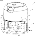
Fig. 1 ] Lafigure 1 illustre une vue d'ensemble d'un appareil de cuisson dans le logement de l'embase duquel est placé un récipient de cuisson ; - [
Fig. 2 ] Lafigure 2 illustre un récipient de cuisson apte à venir se placer dans le logement de l'embase de l'appareil de cuisson ; - [
Fig. 3 ] Lafigure 3 illustre la présence d'un joint d'étanchéité sur le bord de l'ouverture supérieure d'un récipient de cuisson ; - [
Fig. 4 ] Lafigure 4 illustre une vue d'ensemble d'un appareil de cuisson sans récipient de cuisson ; - [
Fig. 5 ] Lafigure 5 illustre un ustensile de cuisson du type grille ; - [
Fig. 6 ] Lafigure 6 illustre un bloc de chauffe isolé, correspondant à une variante de l'appareil de cuisson pour laquelle ledit bloc de chauffe est amovible de l'embase ; - [
Fig. 7 ] Lafigure 7 illustre le bloc de chauffe de lafigure 6 rapporté directement sur un récipient de cuisson.
- [
Fig. 1 ] Thefigure 1 illustrates an overall view of a cooking appliance in the housing of the base of which a cooking receptacle is placed; - [
Fig. 2 ] Thefigure 2 illustrates a cooking vessel capable of being placed in the housing of the base of the cooking appliance; - [
Fig. 3 ] Thefigure 3 illustrates the presence of a seal on the edge of the top opening of a cooking vessel; - [
Fig. 4 ] Thefigure 4 illustrates an overall view of a cooking appliance without a cooking vessel; - [
Fig. 5 ] Thefigure 5 illustrates a grill type cooking utensil; - [
Fig. 6 ] Thefigure 6 illustrates an insulated heating block, corresponding to a variant of the cooking appliance for which said heating block is removable from the base; - [
Fig. 7 ] Thefigure 7 illustrates the heating block of thefigure 6 attached directly to a cooking vessel.
Dans la suite de la description, le terme appareil est utilisé pour désigner un appareil 1 de cuisson à air chaud selon l'invention. De même, le terme récipient est utilisé pour désigner le récipient de cuisson selon l'invention. En outre, les mêmes références sont utilisées pour désigner les caractéristiques identiques ou équivalentes selon les diverses variantes de réalisation de l'appareil et du récipient.In the remainder of the description, the term appliance is used to denote a hot
En regard des
Le bloc de chauffe 2 permet de faire circuler de l'air chaud vers le bas en direction du logement 9 de sorte que lorsque le récipient 10 est placé dans ledit logement 9, ledit air chaud circule dans ledit récipient 10. Le bloc de chauffe 2 est conçu pour faire circuler en cycle cet air chaud de sorte à le réchauffer et le renvoyer dans ledit récipient 10 disposé sous ledit bloc de chauffe 2. Ce bloc de chauffe 2 comprend une entrée d'air, un dispositif de chauffe de l'air du type résistif (non illustré) et un dispositif de circulation d'air chaud du type ventilateur (non illustré), comme cela existe déjà traditionnellement sur les appareils de cuisson à air chaud du type friteuse à air chaud.The
A la différence des appareils de cuisson traditionnels qui prévoient de placer une cuve et éventuellement un panier dans une enceinte de cuisson fermée, l'appareil 1 selon l'invention prévoit préférentiellement d'assurer une étanchéité entre le bloc de chauffe 2 et le récipient 10 lorsque celui-ci est placé dans le logement 9 sur l'embase 3, de sorte à éviter que l'air chaud circulant dans le récipient 10 ne s'échappe par le haut dudit récipient 10. Pour cela un joint d'étanchéité 11 peut être placé sur le bord 12 de l'ouverture supérieure 13 du récipient 10, comme l'illustre la
Des variantes sont aussi envisageables sans étanchéité entre le récipient 10 et le bloc de chauffe 2 de l'appareil 1, en conservant un léger écart 16 entre le bord 12 de l'ouverture supérieure 13 du récipient 10 et le bord 14 de l'ouverture inférieure 15 du bloc de chauffe 2, comme l'illustre la
Comme illustré sur les
Les parties plates 20a, 21a des éléments de préhension 20, 21 peuvent venir en appui sur les faces inférieures 17a, 18a des découpes 17, 18 de sorte que lesdits éléments de préhension 20, 21 soient supportés par les parois latérales 5, 6 une fois le récipient 10 inséré dans le logement 9. Cela permet de positionner dans le logement 9 des récipients 10 présentant des contenances différentes, c'est-à-dire avec des hauteurs différentes de contour 19, tout en conservant un écart 16 identique entre le bord 12 de l'ouverture supérieure 13 du récipient 10 et le bord 14 de l'ouverture inférieure 15 du bloc de chauffe 2. Dans ce cas, seule varie la position du fond 22 du récipient 10 vis-à-vis de la face supérieure 23 du socle 4 de l'embase 3, ledit fond 22 étant plus ou moins écarté de ladite face supérieure 23 en fonction de la hauteur du contour 19 du récipient 10 lorsque les éléments de préhension 20, 21 reposent sur les faces inférieures 17a, 18a des découpes 17, 18.The
Comme illustré sur les
D'autres caractéristiques sont envisageables sur l'appareil 1 afin d'élever le récipient 10 dans le logement 9 de l'embase 3, indépendamment de la hauteur du contour 19 du récipient 10 qui est utilisé. En effet, il est possible de prévoir des rampes d'élévation (non illustrées) inclinées vers le haut directement sur les faces inférieures 17a, 18a des découpes 17, 18, les parties plates 20a, 21a des éléments de préhension 20, 21 prenant appui sur ces rampes durant l'insertion du récipient 10 dans le logement 9, permettant ainsi de rehausser ledit récipient 10.Other characteristics can be envisaged on the
Des caractéristiques additionnelles sont envisageables sur l'appareil 1 afin d'empêcher le retrait du récipient 10 du logement 9. En effet, l'appareil 1 peut par exemple comprendre un dispositif de sécurité (non illustré) permettant de bloquer les éléments de préhension 20, 21 en position dans les découpes 17, 18. Ce dispositif de sécurité peut par exemple comporter deux pièces de blocage qui sont articulées sur les parois latérales 5, 6 pour être déplacées directement à la main ou indirectement en actionnant des organes de manœuvre agissant respectivement sur lesdites pièces de blocage, dans une première position où les pièces de blocage sont dégagées des découpes 17, 18 pour permettre aux éléments de préhension 20, 21 de traverser les découpes et dans une seconde position où lesdites pièces de blocage ferment les découpes 17, 18 au niveau des bords libres 5a, 6a des parois latérales 5, 6 pour empêcher l'extraction des éléments de préhension 20, 21 desdites découpes 17, 18.Additional features can be envisaged on the
Des caractéristiques additionnelles sont envisageables sur l'appareil 1 afin de permettre son utilisation avec un ustensile de cuisson 25 disposé en lieu et place du récipient 10 dans le logement 9. Par exemple, cet ustensile de cuisson 25 peut être une grille 26, illustrée en
L'invention concerne également un système de cuisson qui comprend un appareil 1 présentant les caractéristiques précitées et un kit d'accessoires qui comprend au moins un récipient 10. De préférence, le kit d'accessoires comprendra plusieurs récipients 10 qui pourront avoir des hauteurs de contour 19 différentes et/ou être conçus dans des matériaux différents, par exemple en verre transparent, en verre opaque, en inox, en aluminium voire d'autres matériaux avec un revêtement adapté pour la cuisson d'aliments. Le kit d'accessoires pourra aussi comporter un ou plusieurs couvercles adaptés aux divers récipients de sorte à couvrir le récipient 10 une fois celui-ci extrait du logement 9 et de pouvoir conserver la chaleur dans ledit récipient 10 contenant les aliments cuits. Ce kit d'accessoires pourra aussi comporter des ustensiles de cuisson 25 tels que présentés précédemment, dans une version adaptée de l'appareil 1.The invention also relates to a cooking system which comprises an
D'autres variantes sont envisageables dans le cadre de l'invention. Par exemple, les éléments de préhension 20, 21 pourront être d'une forme différente et les découpes 17, 18 sur les parois latérales 5, 6 pourront avoir une forme différente de celle d'une fente de sorte à les adapter auxdits éléments de préhension 20, 21.Other variants can be envisaged within the framework of the invention. For example, the
Dans l'appareil 1 apparaissant dans les
Claims (16)
- Hot air cooking appliance (1), which comprises a heating block (2) arranged in the upper part and a base (3) arranged in the lower part and comprising a housing (9) above which is located the heating block (2), said housing (9) being capable of receiving a cooking vessel (10) equipped with an upper opening (13) intended to be disposed facing said heating block (2), the base (3) comprising a front opening (8) communicating with the housing (9) and capable of enabling the passage of the cooking vessel (10) for its insertion into said housing (9) and its removal from it, said base (3) further comprising two side walls (5, 6) each equipped with a free edge (5a, 6a) contiguous to the front opening (8), characterised in that said two side walls are also equipped with a transverse cutout (17, 18) on said side wall (5, 6) and leading to said free edge (5a, 6a), each of the cutouts (17, 18) being capable of receiving an element for gripping (20, 21) the cooking vessel (10) so as to preserve manual access to each element for gripping (20, 21) said cooking vessel (10) by said side walls (5, 6) during the insertion of the cooking vessel into said housing (9) or of the removal of the cooking vessel (10) from said housing (9) and capable of enabling the passage of the elements for gripping (20, 21) the cooking vessel (10) by letting them exceed outside of the side walls (5, 6) when said cooking vessel (10) is inserted into the housing (9), and in that the heating block (2) is removably mounted on the base (3), said heating block being capable of being placed directly on an upper opening (13) of a cooking vessel (10) independently from said base (3).
- Hot air cooking appliance (1) according to claim 1, wherein the cutouts (17, 18) are capable of supporting the elements for gripping (20, 21) the cooking vessel (10) when said cooking vessel (10) is inserted into the housing (9).
- Hot air cooking appliance (1) according to one of claims 1 or 2, wherein the base (3) comprises a stand (4) arranged under the front opening (8) and the housing (9), the stand comprising a guiding system capable of aligning at the top the elements for gripping (20, 21) the cooking vessel (10) with the cutouts (17, 18) at the start of inserting the cooking vessel (10) through the front opening (8).
- Hot air cooking appliance (1) according to claim 3, wherein the guiding system comprises at least one guiding ramp, preferably three guiding ramps (24a, 24b, 24c).
- Hot air cooking appliance (1) according to any one of claims 1 to 4, which comprises a lifting system implemented on a stand of the base or on the cutouts of the side walls of the base and capable of elevating the cooking vessel (10) during its insertion into the housing (9) so as to bring the upper opening (13) of the cooking vessel (10) close to the heating block (2).
- Hot air cooking appliance (1) according to any one of claims 1 to 5, which comprises a safety device capable of preventing the insertion of a cooking vessel into the housing or the removal of a cooking vessel (10) from the housing (9).
- Hot air cooking appliance (1) according to any one of claims 1 to 6, wherein the side walls (5, 6) of the base (3) each comprise on their inner face (5b, 6b) at least one support element capable of receiving a bearing element (27a, 27b) of a cooking utensil (25) by keeping said cooking utensil (25) away from the heating block (2).
- Hot air cooking appliance (1) according to claim 7, wherein the inner faces (5b, 6b) of the side walls (5, 6) each comprise at least two support elements arranged at different heights on each of said inner faces (5b, 6b), said support elements being capable of receiving either a bearing element (27a, 27b) of a cooking utensil (25) by keeping away from the heating block (2) according to at least two different heights.
- Cooking system comprising a hot air cooking appliance (1) having the features of any one of claims 1 to 8 and a cooking accessory kit comprising at least one cooking vessel (10) equipped with an upper opening (13) and with two gripping elements (20, 21), said at least one cooking vessel (10) being capable of being inserted into the housing (9) of the base (3) of the hot air cooking appliance (1) by passing through the front opening (8) and by placing the two gripping elements (20, 21) respectively in the two cutouts (17, 18) on the side walls (5, 6) of said base (3).
- Cooking system according to claim 9, wherein a sealing system is implemented between the upper opening (13) of the at least one cooking vessel (10) and the heating block (2) when said at least one cooking vessel (10) is inserted into the housing (9).
- Cooking system according to claim 10, wherein the sealing system comprises a seal (11) arranged on an edge (12) of the upper opening (13) of the at least one cooking vessel (10) or on an edge (14) of a lower opening (15) of the heating block (2).
- Cooking system according to any one of claims 9 to 11, wherein the gripping elements (20, 21) on the at least one cooking vessel (10) are flat and the cutouts (17, 18) on the side walls (5, 6) of the base (3) of the cooking appliance having the form of a slope.
- Cooking system according to any one of claims 9 to 12, wherein the at least one cooking vessel (10) is transparent.
- Cooking system according to any one of claims 9 to 13, wherein the cooking accessory kit comprises at least one lid capable of being placed on the upper opening (13) of the at least one cooking vessel (10).
- Cooking system according to any one of claims 9 to 14, the hot air cooking appliance (1) comprising the features of any one of claims 1 to 8, wherein the cooking accessory kit comprises at least one cooking utensil (25) complementary to the at least one cooking vessel (10), each cooking utensil (25) comprising two bearing elements (27a, 27b) capable of resting on the at least one support element of the inner faces (5b, 6b) of the two side walls (5, 6) of the base (3) so as to keep said cooking utensil (25) in the housing (9) of the base (3) with a gap relative to the heating block (2).
- Cooking system according to claim 15, wherein the at least one cooking utensil (25) is chosen from among a grille (26), a plate and a flat, rigid mould equipped with indentations.
Applications Claiming Priority (1)
| Application Number | Priority Date | Filing Date | Title |
|---|---|---|---|
| FR1903861A FR3094883B1 (en) | 2019-04-11 | 2019-04-11 | HOT AIR COOKING APPLIANCE WITH A FRONT OPENING FOR THE INSERTION AND REMOVAL OF A COOKING CONTAINER |
Publications (2)
| Publication Number | Publication Date |
|---|---|
| EP3721760A1 EP3721760A1 (en) | 2020-10-14 |
| EP3721760B1 true EP3721760B1 (en) | 2021-11-17 |
Family
ID=67875564
Family Applications (1)
| Application Number | Title | Priority Date | Filing Date |
|---|---|---|---|
| EP20169044.3A Active EP3721760B1 (en) | 2019-04-11 | 2020-04-09 | Hot air cooking apparatus with a front opening for inserting and removing a cooking device |
Country Status (3)
| Country | Link |
|---|---|
| EP (1) | EP3721760B1 (en) |
| CN (1) | CN111802922A (en) |
| FR (1) | FR3094883B1 (en) |
Family Cites Families (5)
| Publication number | Priority date | Publication date | Assignee | Title |
|---|---|---|---|---|
| WO2012032449A1 (en) * | 2010-09-10 | 2012-03-15 | Koninklijke Philips Electronics N.V. | Apparatus for preparing food |
| FR2982755B1 (en) * | 2011-11-22 | 2014-01-17 | Seb Sa | COOKING APPARATUS COMPRISING A FILTRATION ATTACHMENT WHICH MAY OCCUPY TWO POSITIONS |
| CN203195501U (en) * | 2013-04-03 | 2013-09-18 | 张一骋 | Rectangular drawer type smokeless airfryer |
| US10602869B2 (en) * | 2014-11-28 | 2020-03-31 | Kitchen Mate Inc. | Apparatus for automatic meal preparation |
| CN105595858B (en) * | 2016-02-26 | 2017-12-29 | 宁波比依电器有限公司 | Air fryer |
-
2019
- 2019-04-11 FR FR1903861A patent/FR3094883B1/en active Active
-
2020
- 2020-04-09 EP EP20169044.3A patent/EP3721760B1/en active Active
- 2020-04-09 CN CN202010272008.9A patent/CN111802922A/en active Pending
Also Published As
| Publication number | Publication date |
|---|---|
| CN111802922A (en) | 2020-10-23 |
| FR3094883A1 (en) | 2020-10-16 |
| EP3721760A1 (en) | 2020-10-14 |
| FR3094883B1 (en) | 2021-04-30 |
Similar Documents
| Publication | Publication Date | Title |
|---|---|---|
| EP1057437B1 (en) | Multifunctional culinary apparatus | |
| EP2052654B1 (en) | Cookware with stirring system and associated method | |
| CA2821569C (en) | Food cooking appliance comprising a stirring blade | |
| EP3542686A1 (en) | Cooking appliance such as a hot air fryer | |
| BE1005409A0 (en) | Containers cover. | |
| EP3897318B1 (en) | Cooking appliance of the hot-air fryer type provided with a basket having deflectors | |
| EP2967254B1 (en) | Grill with at least to removeable panels | |
| FR2912633A1 (en) | APPARATUS FOR COOKING AND DRAINING FOODS IN A LIQUID COMPRISING EVAPORATION PUNCHES AND DRIPPING PERFORATIONS | |
| EP3785583A1 (en) | Hot air cooking appliance with several functional configurations | |
| FR3034972A3 (en) | GRILL KIT | |
| EP3721760B1 (en) | Hot air cooking apparatus with a front opening for inserting and removing a cooking device | |
| FR2807307A1 (en) | Accessories, for vertical shaft electric roaster, comprises toothed wheel which fits on to vertical shaft and drives basket utensil mounted on a horizontal shaft through second toothed wheel | |
| EP2536316A1 (en) | Basket for an electrical appliance for steam-heating food or for a cooking utensil | |
| EP3785582B1 (en) | Hot air cooking appliance with compact size in a storage configuration | |
| EP3785584B1 (en) | Hot air cooking appliance provided with a base for receiving a cooking vessel and a locking device between the container and the base | |
| EP3597086A1 (en) | Cooking appliance such as a hot air fryer with accessories for preparing various foods | |
| WO2007009195A1 (en) | Cooking appliance | |
| FR2682273A3 (en) | Utensil for performing a variety of cooking tasks | |
| EP0039631B1 (en) | Portable grilling device | |
| EP3628197A1 (en) | Cooking appliance equipped with a fondue pot with reversible shelf | |
| EP0811346A1 (en) | Table cooking apparatus for multiple uses | |
| EP3708044A1 (en) | Kit of elements for assembling a container of a cooking apparatus such as a hot air fryer | |
| FR2481590A1 (en) | Table top cooking unit - has spits between heating elements under glass cover, supported above drip tray forming cooling zone | |
| CH207698A (en) | Cooking stove. | |
| WO2012153307A1 (en) | Gas cooking device |
Legal Events
| Date | Code | Title | Description |
|---|---|---|---|
| PUAI | Public reference made under article 153(3) epc to a published international application that has entered the european phase |
Free format text: ORIGINAL CODE: 0009012 |
|
| STAA | Information on the status of an ep patent application or granted ep patent |
Free format text: STATUS: THE APPLICATION HAS BEEN PUBLISHED |
|
| AK | Designated contracting states |
Kind code of ref document: A1 Designated state(s): AL AT BE BG CH CY CZ DE DK EE ES FI FR GB GR HR HU IE IS IT LI LT LU LV MC MK MT NL NO PL PT RO RS SE SI SK SM TR |
|
| AX | Request for extension of the european patent |
Extension state: BA ME |
|
| STAA | Information on the status of an ep patent application or granted ep patent |
Free format text: STATUS: REQUEST FOR EXAMINATION WAS MADE |
|
| 17P | Request for examination filed |
Effective date: 20210411 |
|
| RBV | Designated contracting states (corrected) |
Designated state(s): AL AT BE BG CH CY CZ DE DK EE ES FI FR GB GR HR HU IE IS IT LI LT LU LV MC MK MT NL NO PL PT RO RS SE SI SK SM TR |
|
| GRAP | Despatch of communication of intention to grant a patent |
Free format text: ORIGINAL CODE: EPIDOSNIGR1 |
|
| STAA | Information on the status of an ep patent application or granted ep patent |
Free format text: STATUS: GRANT OF PATENT IS INTENDED |
|
| RIC1 | Information provided on ipc code assigned before grant |
Ipc: A47J 37/06 20060101AFI20210428BHEP |
|
| INTG | Intention to grant announced |
Effective date: 20210602 |
|
| GRAS | Grant fee paid |
Free format text: ORIGINAL CODE: EPIDOSNIGR3 |
|
| GRAA | (expected) grant |
Free format text: ORIGINAL CODE: 0009210 |
|
| STAA | Information on the status of an ep patent application or granted ep patent |
Free format text: STATUS: THE PATENT HAS BEEN GRANTED |
|
| AK | Designated contracting states |
Kind code of ref document: B1 Designated state(s): AL AT BE BG CH CY CZ DE DK EE ES FI FR GB GR HR HU IE IS IT LI LT LU LV MC MK MT NL NO PL PT RO RS SE SI SK SM TR |
|
| REG | Reference to a national code |
Ref country code: GB Ref legal event code: FG4D Free format text: NOT ENGLISH |
|
| REG | Reference to a national code |
Ref country code: IE Ref legal event code: FG4D Free format text: LANGUAGE OF EP DOCUMENT: FRENCH |
|
| REG | Reference to a national code |
Ref country code: DE Ref legal event code: R096 Ref document number: 602020001012 Country of ref document: DE |
|
| REG | Reference to a national code |
Ref country code: AT Ref legal event code: REF Ref document number: 1447366 Country of ref document: AT Kind code of ref document: T Effective date: 20211215 |
|
| REG | Reference to a national code |
Ref country code: NL Ref legal event code: FP |
|
| REG | Reference to a national code |
Ref country code: LT Ref legal event code: MG9D |
|
| REG | Reference to a national code |
Ref country code: AT Ref legal event code: MK05 Ref document number: 1447366 Country of ref document: AT Kind code of ref document: T Effective date: 20211117 |
|
| PG25 | Lapsed in a contracting state [announced via postgrant information from national office to epo] |
Ref country code: RS Free format text: LAPSE BECAUSE OF FAILURE TO SUBMIT A TRANSLATION OF THE DESCRIPTION OR TO PAY THE FEE WITHIN THE PRESCRIBED TIME-LIMIT Effective date: 20211117 Ref country code: LT Free format text: LAPSE BECAUSE OF FAILURE TO SUBMIT A TRANSLATION OF THE DESCRIPTION OR TO PAY THE FEE WITHIN THE PRESCRIBED TIME-LIMIT Effective date: 20211117 Ref country code: FI Free format text: LAPSE BECAUSE OF FAILURE TO SUBMIT A TRANSLATION OF THE DESCRIPTION OR TO PAY THE FEE WITHIN THE PRESCRIBED TIME-LIMIT Effective date: 20211117 Ref country code: BG Free format text: LAPSE BECAUSE OF FAILURE TO SUBMIT A TRANSLATION OF THE DESCRIPTION OR TO PAY THE FEE WITHIN THE PRESCRIBED TIME-LIMIT Effective date: 20220217 Ref country code: AT Free format text: LAPSE BECAUSE OF FAILURE TO SUBMIT A TRANSLATION OF THE DESCRIPTION OR TO PAY THE FEE WITHIN THE PRESCRIBED TIME-LIMIT Effective date: 20211117 |
|
| PG25 | Lapsed in a contracting state [announced via postgrant information from national office to epo] |
Ref country code: IS Free format text: LAPSE BECAUSE OF FAILURE TO SUBMIT A TRANSLATION OF THE DESCRIPTION OR TO PAY THE FEE WITHIN THE PRESCRIBED TIME-LIMIT Effective date: 20220317 Ref country code: SE Free format text: LAPSE BECAUSE OF FAILURE TO SUBMIT A TRANSLATION OF THE DESCRIPTION OR TO PAY THE FEE WITHIN THE PRESCRIBED TIME-LIMIT Effective date: 20211117 Ref country code: PT Free format text: LAPSE BECAUSE OF FAILURE TO SUBMIT A TRANSLATION OF THE DESCRIPTION OR TO PAY THE FEE WITHIN THE PRESCRIBED TIME-LIMIT Effective date: 20220317 Ref country code: PL Free format text: LAPSE BECAUSE OF FAILURE TO SUBMIT A TRANSLATION OF THE DESCRIPTION OR TO PAY THE FEE WITHIN THE PRESCRIBED TIME-LIMIT Effective date: 20211117 Ref country code: NO Free format text: LAPSE BECAUSE OF FAILURE TO SUBMIT A TRANSLATION OF THE DESCRIPTION OR TO PAY THE FEE WITHIN THE PRESCRIBED TIME-LIMIT Effective date: 20220217 Ref country code: LV Free format text: LAPSE BECAUSE OF FAILURE TO SUBMIT A TRANSLATION OF THE DESCRIPTION OR TO PAY THE FEE WITHIN THE PRESCRIBED TIME-LIMIT Effective date: 20211117 Ref country code: HR Free format text: LAPSE BECAUSE OF FAILURE TO SUBMIT A TRANSLATION OF THE DESCRIPTION OR TO PAY THE FEE WITHIN THE PRESCRIBED TIME-LIMIT Effective date: 20211117 Ref country code: GR Free format text: LAPSE BECAUSE OF FAILURE TO SUBMIT A TRANSLATION OF THE DESCRIPTION OR TO PAY THE FEE WITHIN THE PRESCRIBED TIME-LIMIT Effective date: 20220218 |
|
| PG25 | Lapsed in a contracting state [announced via postgrant information from national office to epo] |
Ref country code: SM Free format text: LAPSE BECAUSE OF FAILURE TO SUBMIT A TRANSLATION OF THE DESCRIPTION OR TO PAY THE FEE WITHIN THE PRESCRIBED TIME-LIMIT Effective date: 20211117 Ref country code: SK Free format text: LAPSE BECAUSE OF FAILURE TO SUBMIT A TRANSLATION OF THE DESCRIPTION OR TO PAY THE FEE WITHIN THE PRESCRIBED TIME-LIMIT Effective date: 20211117 Ref country code: RO Free format text: LAPSE BECAUSE OF FAILURE TO SUBMIT A TRANSLATION OF THE DESCRIPTION OR TO PAY THE FEE WITHIN THE PRESCRIBED TIME-LIMIT Effective date: 20211117 Ref country code: ES Free format text: LAPSE BECAUSE OF FAILURE TO SUBMIT A TRANSLATION OF THE DESCRIPTION OR TO PAY THE FEE WITHIN THE PRESCRIBED TIME-LIMIT Effective date: 20211117 Ref country code: EE Free format text: LAPSE BECAUSE OF FAILURE TO SUBMIT A TRANSLATION OF THE DESCRIPTION OR TO PAY THE FEE WITHIN THE PRESCRIBED TIME-LIMIT Effective date: 20211117 Ref country code: DK Free format text: LAPSE BECAUSE OF FAILURE TO SUBMIT A TRANSLATION OF THE DESCRIPTION OR TO PAY THE FEE WITHIN THE PRESCRIBED TIME-LIMIT Effective date: 20211117 Ref country code: CZ Free format text: LAPSE BECAUSE OF FAILURE TO SUBMIT A TRANSLATION OF THE DESCRIPTION OR TO PAY THE FEE WITHIN THE PRESCRIBED TIME-LIMIT Effective date: 20211117 |
|
| REG | Reference to a national code |
Ref country code: DE Ref legal event code: R097 Ref document number: 602020001012 Country of ref document: DE |
|
| PLBE | No opposition filed within time limit |
Free format text: ORIGINAL CODE: 0009261 |
|
| STAA | Information on the status of an ep patent application or granted ep patent |
Free format text: STATUS: NO OPPOSITION FILED WITHIN TIME LIMIT |
|
| 26N | No opposition filed |
Effective date: 20220818 |
|
| PG25 | Lapsed in a contracting state [announced via postgrant information from national office to epo] |
Ref country code: AL Free format text: LAPSE BECAUSE OF FAILURE TO SUBMIT A TRANSLATION OF THE DESCRIPTION OR TO PAY THE FEE WITHIN THE PRESCRIBED TIME-LIMIT Effective date: 20211117 |
|
| PG25 | Lapsed in a contracting state [announced via postgrant information from national office to epo] |
Ref country code: SI Free format text: LAPSE BECAUSE OF FAILURE TO SUBMIT A TRANSLATION OF THE DESCRIPTION OR TO PAY THE FEE WITHIN THE PRESCRIBED TIME-LIMIT Effective date: 20211117 |
|
| PG25 | Lapsed in a contracting state [announced via postgrant information from national office to epo] |
Ref country code: MC Free format text: LAPSE BECAUSE OF FAILURE TO SUBMIT A TRANSLATION OF THE DESCRIPTION OR TO PAY THE FEE WITHIN THE PRESCRIBED TIME-LIMIT Effective date: 20211117 Ref country code: LU Free format text: LAPSE BECAUSE OF NON-PAYMENT OF DUE FEES Effective date: 20220409 |
|
| PG25 | Lapsed in a contracting state [announced via postgrant information from national office to epo] |
Ref country code: IE Free format text: LAPSE BECAUSE OF NON-PAYMENT OF DUE FEES Effective date: 20220409 |
|
| PG25 | Lapsed in a contracting state [announced via postgrant information from national office to epo] |
Ref country code: IT Free format text: LAPSE BECAUSE OF FAILURE TO SUBMIT A TRANSLATION OF THE DESCRIPTION OR TO PAY THE FEE WITHIN THE PRESCRIBED TIME-LIMIT Effective date: 20211117 |
|
| PGFP | Annual fee paid to national office [announced via postgrant information from national office to epo] |
Ref country code: FR Payment date: 20230425 Year of fee payment: 4 Ref country code: DE Payment date: 20230412 Year of fee payment: 4 |
|
| PGFP | Annual fee paid to national office [announced via postgrant information from national office to epo] |
Ref country code: BE Payment date: 20230424 Year of fee payment: 4 |
|
| REG | Reference to a national code |
Ref country code: CH Ref legal event code: PL |
|
| PG25 | Lapsed in a contracting state [announced via postgrant information from national office to epo] |
Ref country code: LI Free format text: LAPSE BECAUSE OF NON-PAYMENT OF DUE FEES Effective date: 20230430 Ref country code: CH Free format text: LAPSE BECAUSE OF NON-PAYMENT OF DUE FEES Effective date: 20230430 |
|
| PGFP | Annual fee paid to national office [announced via postgrant information from national office to epo] |
Ref country code: NL Payment date: 20240325 Year of fee payment: 5 |
|
| PG25 | Lapsed in a contracting state [announced via postgrant information from national office to epo] |
Ref country code: MK Free format text: LAPSE BECAUSE OF FAILURE TO SUBMIT A TRANSLATION OF THE DESCRIPTION OR TO PAY THE FEE WITHIN THE PRESCRIBED TIME-LIMIT Effective date: 20211117 Ref country code: CY Free format text: LAPSE BECAUSE OF FAILURE TO SUBMIT A TRANSLATION OF THE DESCRIPTION OR TO PAY THE FEE WITHIN THE PRESCRIBED TIME-LIMIT Effective date: 20211117 |