EP3720385B1 - Système de pose d'implant médical - Google Patents
Système de pose d'implant médical Download PDFInfo
- Publication number
- EP3720385B1 EP3720385B1 EP18822226.9A EP18822226A EP3720385B1 EP 3720385 B1 EP3720385 B1 EP 3720385B1 EP 18822226 A EP18822226 A EP 18822226A EP 3720385 B1 EP3720385 B1 EP 3720385B1
- Authority
- EP
- European Patent Office
- Prior art keywords
- frame
- implant
- attachment
- tack
- shaft
- Prior art date
- Legal status (The legal status is an assumption and is not a legal conclusion. Google has not performed a legal analysis and makes no representation as to the accuracy of the status listed.)
- Active
Links
- 239000007943 implant Substances 0.000 title claims description 279
- 239000000463 material Substances 0.000 claims description 38
- 210000000988 bone and bone Anatomy 0.000 claims description 34
- 210000002435 tendon Anatomy 0.000 description 46
- 238000000034 method Methods 0.000 description 29
- 238000003780 insertion Methods 0.000 description 15
- 230000037431 insertion Effects 0.000 description 15
- 210000004095 humeral head Anatomy 0.000 description 13
- 208000027418 Wounds and injury Diseases 0.000 description 11
- 230000006378 damage Effects 0.000 description 10
- 230000008439 repair process Effects 0.000 description 10
- 210000000513 rotator cuff Anatomy 0.000 description 10
- 230000001054 cortical effect Effects 0.000 description 8
- 210000002758 humerus Anatomy 0.000 description 8
- 230000007246 mechanism Effects 0.000 description 6
- 230000006870 function Effects 0.000 description 5
- 238000004519 manufacturing process Methods 0.000 description 5
- 230000013011 mating Effects 0.000 description 5
- 102000010834 Extracellular Matrix Proteins Human genes 0.000 description 4
- 108010037362 Extracellular Matrix Proteins Proteins 0.000 description 4
- 208000026137 Soft tissue injury Diseases 0.000 description 4
- 239000000853 adhesive Substances 0.000 description 4
- 230000001070 adhesive effect Effects 0.000 description 4
- 238000004873 anchoring Methods 0.000 description 4
- 238000013461 design Methods 0.000 description 4
- 210000002744 extracellular matrix Anatomy 0.000 description 4
- 238000001746 injection moulding Methods 0.000 description 4
- 210000001991 scapula Anatomy 0.000 description 4
- 238000012546 transfer Methods 0.000 description 4
- 241001653121 Glenoides Species 0.000 description 3
- 210000003484 anatomy Anatomy 0.000 description 3
- 238000001727 in vivo Methods 0.000 description 3
- 208000014674 injury Diseases 0.000 description 3
- 239000002184 metal Substances 0.000 description 3
- 230000000399 orthopedic effect Effects 0.000 description 3
- 229920000642 polymer Polymers 0.000 description 3
- 210000004872 soft tissue Anatomy 0.000 description 3
- 238000004804 winding Methods 0.000 description 3
- 208000024288 Rotator Cuff injury Diseases 0.000 description 2
- 208000021945 Tendon injury Diseases 0.000 description 2
- 230000001154 acute effect Effects 0.000 description 2
- 230000009286 beneficial effect Effects 0.000 description 2
- 229910010293 ceramic material Inorganic materials 0.000 description 2
- 239000002131 composite material Substances 0.000 description 2
- 230000006835 compression Effects 0.000 description 2
- 238000007906 compression Methods 0.000 description 2
- 238000010168 coupling process Methods 0.000 description 2
- 238000005859 coupling reaction Methods 0.000 description 2
- 238000002788 crimping Methods 0.000 description 2
- 230000003247 decreasing effect Effects 0.000 description 2
- 238000002513 implantation Methods 0.000 description 2
- 239000003550 marker Substances 0.000 description 2
- 239000011159 matrix material Substances 0.000 description 2
- 239000002861 polymer material Substances 0.000 description 2
- 238000007639 printing Methods 0.000 description 2
- 230000008569 process Effects 0.000 description 2
- 210000001519 tissue Anatomy 0.000 description 2
- 230000000472 traumatic effect Effects 0.000 description 2
- 230000000007 visual effect Effects 0.000 description 2
- 238000003466 welding Methods 0.000 description 2
- 230000008901 benefit Effects 0.000 description 1
- 230000008859 change Effects 0.000 description 1
- 238000006243 chemical reaction Methods 0.000 description 1
- 230000008878 coupling Effects 0.000 description 1
- 238000005538 encapsulation Methods 0.000 description 1
- 210000003041 ligament Anatomy 0.000 description 1
- 230000014759 maintenance of location Effects 0.000 description 1
- 239000007769 metal material Substances 0.000 description 1
- 238000012986 modification Methods 0.000 description 1
- 230000004048 modification Effects 0.000 description 1
- 210000003205 muscle Anatomy 0.000 description 1
- 210000000323 shoulder joint Anatomy 0.000 description 1
Images


Classifications
-
- A—HUMAN NECESSITIES
- A61—MEDICAL OR VETERINARY SCIENCE; HYGIENE
- A61F—FILTERS IMPLANTABLE INTO BLOOD VESSELS; PROSTHESES; DEVICES PROVIDING PATENCY TO, OR PREVENTING COLLAPSING OF, TUBULAR STRUCTURES OF THE BODY, e.g. STENTS; ORTHOPAEDIC, NURSING OR CONTRACEPTIVE DEVICES; FOMENTATION; TREATMENT OR PROTECTION OF EYES OR EARS; BANDAGES, DRESSINGS OR ABSORBENT PADS; FIRST-AID KITS
- A61F2/00—Filters implantable into blood vessels; Prostheses, i.e. artificial substitutes or replacements for parts of the body; Appliances for connecting them with the body; Devices providing patency to, or preventing collapsing of, tubular structures of the body, e.g. stents
- A61F2/02—Prostheses implantable into the body
- A61F2/08—Muscles; Tendons; Ligaments
- A61F2/0811—Fixation devices for tendons or ligaments
-
- A—HUMAN NECESSITIES
- A61—MEDICAL OR VETERINARY SCIENCE; HYGIENE
- A61F—FILTERS IMPLANTABLE INTO BLOOD VESSELS; PROSTHESES; DEVICES PROVIDING PATENCY TO, OR PREVENTING COLLAPSING OF, TUBULAR STRUCTURES OF THE BODY, e.g. STENTS; ORTHOPAEDIC, NURSING OR CONTRACEPTIVE DEVICES; FOMENTATION; TREATMENT OR PROTECTION OF EYES OR EARS; BANDAGES, DRESSINGS OR ABSORBENT PADS; FIRST-AID KITS
- A61F2/00—Filters implantable into blood vessels; Prostheses, i.e. artificial substitutes or replacements for parts of the body; Appliances for connecting them with the body; Devices providing patency to, or preventing collapsing of, tubular structures of the body, e.g. stents
- A61F2/02—Prostheses implantable into the body
- A61F2/08—Muscles; Tendons; Ligaments
- A61F2/0805—Implements for inserting tendons or ligaments
-
- A—HUMAN NECESSITIES
- A61—MEDICAL OR VETERINARY SCIENCE; HYGIENE
- A61B—DIAGNOSIS; SURGERY; IDENTIFICATION
- A61B17/00—Surgical instruments, devices or methods, e.g. tourniquets
- A61B17/064—Surgical staples, i.e. penetrating the tissue
-
- A—HUMAN NECESSITIES
- A61—MEDICAL OR VETERINARY SCIENCE; HYGIENE
- A61B—DIAGNOSIS; SURGERY; IDENTIFICATION
- A61B17/00—Surgical instruments, devices or methods, e.g. tourniquets
- A61B17/064—Surgical staples, i.e. penetrating the tissue
- A61B17/0642—Surgical staples, i.e. penetrating the tissue for bones, e.g. for osteosynthesis or connecting tendon to bone
-
- A—HUMAN NECESSITIES
- A61—MEDICAL OR VETERINARY SCIENCE; HYGIENE
- A61B—DIAGNOSIS; SURGERY; IDENTIFICATION
- A61B17/00—Surgical instruments, devices or methods, e.g. tourniquets
- A61B17/10—Surgical instruments, devices or methods, e.g. tourniquets for applying or removing wound clamps, e.g. containing only one clamp or staple; Wound clamp magazines
-
- A—HUMAN NECESSITIES
- A61—MEDICAL OR VETERINARY SCIENCE; HYGIENE
- A61B—DIAGNOSIS; SURGERY; IDENTIFICATION
- A61B17/00—Surgical instruments, devices or methods, e.g. tourniquets
- A61B2017/00831—Material properties
- A61B2017/00964—Material properties composite
-
- A—HUMAN NECESSITIES
- A61—MEDICAL OR VETERINARY SCIENCE; HYGIENE
- A61B—DIAGNOSIS; SURGERY; IDENTIFICATION
- A61B17/00—Surgical instruments, devices or methods, e.g. tourniquets
- A61B17/064—Surgical staples, i.e. penetrating the tissue
- A61B2017/0647—Surgical staples, i.e. penetrating the tissue having one single leg, e.g. tacks
-
- A—HUMAN NECESSITIES
- A61—MEDICAL OR VETERINARY SCIENCE; HYGIENE
- A61F—FILTERS IMPLANTABLE INTO BLOOD VESSELS; PROSTHESES; DEVICES PROVIDING PATENCY TO, OR PREVENTING COLLAPSING OF, TUBULAR STRUCTURES OF THE BODY, e.g. STENTS; ORTHOPAEDIC, NURSING OR CONTRACEPTIVE DEVICES; FOMENTATION; TREATMENT OR PROTECTION OF EYES OR EARS; BANDAGES, DRESSINGS OR ABSORBENT PADS; FIRST-AID KITS
- A61F2/00—Filters implantable into blood vessels; Prostheses, i.e. artificial substitutes or replacements for parts of the body; Appliances for connecting them with the body; Devices providing patency to, or preventing collapsing of, tubular structures of the body, e.g. stents
- A61F2/0063—Implantable repair or support meshes, e.g. hernia meshes
- A61F2002/0068—Implantable repair or support meshes, e.g. hernia meshes having a special mesh pattern
-
- A—HUMAN NECESSITIES
- A61—MEDICAL OR VETERINARY SCIENCE; HYGIENE
- A61F—FILTERS IMPLANTABLE INTO BLOOD VESSELS; PROSTHESES; DEVICES PROVIDING PATENCY TO, OR PREVENTING COLLAPSING OF, TUBULAR STRUCTURES OF THE BODY, e.g. STENTS; ORTHOPAEDIC, NURSING OR CONTRACEPTIVE DEVICES; FOMENTATION; TREATMENT OR PROTECTION OF EYES OR EARS; BANDAGES, DRESSINGS OR ABSORBENT PADS; FIRST-AID KITS
- A61F2/00—Filters implantable into blood vessels; Prostheses, i.e. artificial substitutes or replacements for parts of the body; Appliances for connecting them with the body; Devices providing patency to, or preventing collapsing of, tubular structures of the body, e.g. stents
- A61F2/0063—Implantable repair or support meshes, e.g. hernia meshes
- A61F2002/0072—Delivery tools therefor
-
- A—HUMAN NECESSITIES
- A61—MEDICAL OR VETERINARY SCIENCE; HYGIENE
- A61F—FILTERS IMPLANTABLE INTO BLOOD VESSELS; PROSTHESES; DEVICES PROVIDING PATENCY TO, OR PREVENTING COLLAPSING OF, TUBULAR STRUCTURES OF THE BODY, e.g. STENTS; ORTHOPAEDIC, NURSING OR CONTRACEPTIVE DEVICES; FOMENTATION; TREATMENT OR PROTECTION OF EYES OR EARS; BANDAGES, DRESSINGS OR ABSORBENT PADS; FIRST-AID KITS
- A61F2/00—Filters implantable into blood vessels; Prostheses, i.e. artificial substitutes or replacements for parts of the body; Appliances for connecting them with the body; Devices providing patency to, or preventing collapsing of, tubular structures of the body, e.g. stents
- A61F2/02—Prostheses implantable into the body
- A61F2/08—Muscles; Tendons; Ligaments
- A61F2/0811—Fixation devices for tendons or ligaments
- A61F2002/0817—Structure of the anchor
-
- A—HUMAN NECESSITIES
- A61—MEDICAL OR VETERINARY SCIENCE; HYGIENE
- A61F—FILTERS IMPLANTABLE INTO BLOOD VESSELS; PROSTHESES; DEVICES PROVIDING PATENCY TO, OR PREVENTING COLLAPSING OF, TUBULAR STRUCTURES OF THE BODY, e.g. STENTS; ORTHOPAEDIC, NURSING OR CONTRACEPTIVE DEVICES; FOMENTATION; TREATMENT OR PROTECTION OF EYES OR EARS; BANDAGES, DRESSINGS OR ABSORBENT PADS; FIRST-AID KITS
- A61F2/00—Filters implantable into blood vessels; Prostheses, i.e. artificial substitutes or replacements for parts of the body; Appliances for connecting them with the body; Devices providing patency to, or preventing collapsing of, tubular structures of the body, e.g. stents
- A61F2/02—Prostheses implantable into the body
- A61F2/08—Muscles; Tendons; Ligaments
- A61F2/0811—Fixation devices for tendons or ligaments
- A61F2002/0847—Mode of fixation of anchor to tendon or ligament
- A61F2002/0858—Fixation of tendon or ligament between anchor and bone, e.g. interference screws, wedges
-
- A—HUMAN NECESSITIES
- A61—MEDICAL OR VETERINARY SCIENCE; HYGIENE
- A61F—FILTERS IMPLANTABLE INTO BLOOD VESSELS; PROSTHESES; DEVICES PROVIDING PATENCY TO, OR PREVENTING COLLAPSING OF, TUBULAR STRUCTURES OF THE BODY, e.g. STENTS; ORTHOPAEDIC, NURSING OR CONTRACEPTIVE DEVICES; FOMENTATION; TREATMENT OR PROTECTION OF EYES OR EARS; BANDAGES, DRESSINGS OR ABSORBENT PADS; FIRST-AID KITS
- A61F2/00—Filters implantable into blood vessels; Prostheses, i.e. artificial substitutes or replacements for parts of the body; Appliances for connecting them with the body; Devices providing patency to, or preventing collapsing of, tubular structures of the body, e.g. stents
- A61F2/02—Prostheses implantable into the body
- A61F2/08—Muscles; Tendons; Ligaments
- A61F2/0811—Fixation devices for tendons or ligaments
- A61F2002/0876—Position of anchor in respect to the bone
- A61F2002/0882—Anchor in or on top of a bone tunnel, i.e. a hole running through the entire bone
-
- A—HUMAN NECESSITIES
- A61—MEDICAL OR VETERINARY SCIENCE; HYGIENE
- A61F—FILTERS IMPLANTABLE INTO BLOOD VESSELS; PROSTHESES; DEVICES PROVIDING PATENCY TO, OR PREVENTING COLLAPSING OF, TUBULAR STRUCTURES OF THE BODY, e.g. STENTS; ORTHOPAEDIC, NURSING OR CONTRACEPTIVE DEVICES; FOMENTATION; TREATMENT OR PROTECTION OF EYES OR EARS; BANDAGES, DRESSINGS OR ABSORBENT PADS; FIRST-AID KITS
- A61F2220/00—Fixations or connections for prostheses classified in groups A61F2/00 - A61F2/26 or A61F2/82 or A61F9/00 or A61F11/00 or subgroups thereof
- A61F2220/0008—Fixation appliances for connecting prostheses to the body
- A61F2220/0016—Fixation appliances for connecting prostheses to the body with sharp anchoring protrusions, e.g. barbs, pins, spikes
-
- A—HUMAN NECESSITIES
- A61—MEDICAL OR VETERINARY SCIENCE; HYGIENE
- A61F—FILTERS IMPLANTABLE INTO BLOOD VESSELS; PROSTHESES; DEVICES PROVIDING PATENCY TO, OR PREVENTING COLLAPSING OF, TUBULAR STRUCTURES OF THE BODY, e.g. STENTS; ORTHOPAEDIC, NURSING OR CONTRACEPTIVE DEVICES; FOMENTATION; TREATMENT OR PROTECTION OF EYES OR EARS; BANDAGES, DRESSINGS OR ABSORBENT PADS; FIRST-AID KITS
- A61F2230/00—Geometry of prostheses classified in groups A61F2/00 - A61F2/26 or A61F2/82 or A61F9/00 or A61F11/00 or subgroups thereof
- A61F2230/0002—Two-dimensional shapes, e.g. cross-sections
- A61F2230/0004—Rounded shapes, e.g. with rounded corners
- A61F2230/0006—Rounded shapes, e.g. with rounded corners circular
-
- A—HUMAN NECESSITIES
- A61—MEDICAL OR VETERINARY SCIENCE; HYGIENE
- A61F—FILTERS IMPLANTABLE INTO BLOOD VESSELS; PROSTHESES; DEVICES PROVIDING PATENCY TO, OR PREVENTING COLLAPSING OF, TUBULAR STRUCTURES OF THE BODY, e.g. STENTS; ORTHOPAEDIC, NURSING OR CONTRACEPTIVE DEVICES; FOMENTATION; TREATMENT OR PROTECTION OF EYES OR EARS; BANDAGES, DRESSINGS OR ABSORBENT PADS; FIRST-AID KITS
- A61F2230/00—Geometry of prostheses classified in groups A61F2/00 - A61F2/26 or A61F2/82 or A61F9/00 or A61F11/00 or subgroups thereof
- A61F2230/0002—Two-dimensional shapes, e.g. cross-sections
- A61F2230/0004—Rounded shapes, e.g. with rounded corners
- A61F2230/0008—Rounded shapes, e.g. with rounded corners elliptical or oval
Definitions
- the present disclosure pertains generally, but not by way of limitation, to orthopedic implants and methods of treatment. More particularly, the present disclosure relates to a tendon repair implant, such as one that is engineered for arthroscopic placement over or in the area of a full or partial thickness tear of the supraspinatus tendon of the shoulder.
- a tendon repair implant such as one that is engineered for arthroscopic placement over or in the area of a full or partial thickness tear of the supraspinatus tendon of the shoulder.
- US 2017/189164 A1 relates to an example medical device.
- the medical device includes an implant delivery system having a delivery shaft including a proximal portion and a distal portion and a detachable frame coupled to the distal portion of the delivery shaft.
- the detachable frame includes a body portion and a plurality of attachment arms extending away from the body portion. The plurality of attachment arms is configured to be attached to an implant and the detachable frame is configured to detach from the delivery shaft in vivo.
- a tack member may extend through a portion of the frame.
- US 2004/220574 A1 relates to orthopedic devices.
- the devices include a part that is made of extracellular matrix material that has been hardened.
- One method of hardening the extracellular matrix is to comminute naturally occurring extracellular matrix and dry the comminuted material.
- the hardened extracellular matrix material can be machined to form a variety of orthopedic devices.
- US 5,261,914 relates to a surgical fastener for attaching soft tissues, e.g., a ligament to a bone.
- the surgical fastener comprises a shank and an enlarged head disposed on one end of the shank.
- a central bore passes completely through the fastener along its longitudinal axis, and a plurality of diametrically projecting ribs are disposed along the length of the shank.
- the invention relates to an implant delivery system as defined in the claims.
- An example implant delivery system includes a delivery shaft including a proximal portion, a distal portion and a lumen extending therebetween.
- the delivery system also includes a frame detachably coupled to the distal portion of the delivery shaft and a tack member coupled to the frame.
- tether member extends within the lumen of the delivery shaft.
- the frame includes a body portion and a plurality of attachment arms extending away from the body portion.
- tack member extends through an aperture in the body portion of the frame.
- a distal end portion of the tack member is configured to engage with a bone.
- retraction of the tether member is designed to disengage the tack member from a bone.
- distal end portion of the tack member includes a tapered region.
- a proximal end portion of the tack member includes a bore extending along a longitudinal axis of the tack member.
- the frame is configured to detach from the delivery shaft in vivo.
- tether is indirectly coupled to the frame via a connection member.
- the frame further comprises a first aperture configured to couple with the connection member.
- connection member includes a first profile and wherein the lumen of the delivery sheath includes a second profile, and wherein the first profile is configured to mate with the second profile.
- connection member is configured to disengage from the delivery shaft, and wherein the connection member is configured to remain engaged to the frame after disengaging from the delivery shaft.
- tack member can translate with respect to the connection member.
- the tack member includes a shaft having a circumferential surface and one or more protrusions extending radially away from the circumferential surface.
- the one or more curved protrusions are configured to anchor the tack member beneath a layer of bone.
- the tack member includes a shaft formed from a first material and one or more fixation members disposed along the shaft, wherein the one or more fixation members are formed from a second material different from the first material.
- the tether extends within the lumen of the delivery shaft while the delivery shaft is attached to the frame, and wherein the tether remains connected to the frame when the delivery shaft is detached from the frame.
- An example method for delivering an implant to repair a tendon includes advancing an implant repair system to a target site.
- the implant repair system includes a delivery shaft including a proximal portion and a distal portion, and a frame detachably coupled to the distal portion of the delivery shaft via a connection member.
- the frame includes a body portion and a plurality of attachment arms extending away from the body portion.
- a tack member is coupled to the connection member.
- An implant is attached to the attachment arms.
- the method further includes positioning the implant adjacent a bony structure of the target site and engaging the tack member with the bony structure. Thereafter, the delivery shaft is detached from the frame in vivo with the tack member remaining engaged with the bony structure. Thereafter, the implant is affixed to the target site.
- connection member is coupled between a distal end of the delivery shaft and the frame, and wherein detaching the delivery shaft from the frame includes disengaging the connection member from the distal end of the delivery shaft.
- engaging the tack member further includes anchoring the tack into the bony structure.
- the tack member includes a shaft having a circumferential surface and one or more curved protrusions extending radially away from the circumferential surface, and wherein anchoring the tack into the bony structure includes positioning the one or more curved portions beneath a cortical layer of bone.
- the tack member includes a shaft formed from a first material and one or more fixation members disposed along the shaft, wherein the one or more fixation members are formed from a second material different from the first material, and wherein anchoring the tack into the bony structure includes positioning the one or more fixation members adjacent a cortical layer of bone.
- the method further comprises withdrawing the frame from the target site after affixing the implant to the target site, and wherein withdrawing the frame from the target site includes retracting a tether coupled to the frame.
- references in the specification to "an embodiment”, “some embodiments”, “other embodiments”, etc. indicate that the embodiment described may include one or more particular features, structures, and/or characteristics. However, such recitations do not necessarily mean that all embodiments include the particular features, structures, and/or characteristics. Additionally, when particular features, structures, and/or characteristics are described in connection with one embodiment, it should be understood that such features, structures, and/or characteristics may also be used connection with other embodiments whether or not explicitly described unless clearly stated to the contrary.
- a common soft tissue injury is damage to the rotator cuff or rotator cuff tendons.
- Damage to the rotator cuff is a potentially serious medical condition that may occur during hyperextension, from an acute traumatic tear or from overuse of the joint.
- Current repair procedures may attempt to alleviate impingement or make room for movement of the tendon to prevent further damage and relieve discomfort but do not repair or strengthen the tendon.
- An accepted treatment for rotator cuff tears may include reattaching the torn tendon to the humeral head using sutures. Additionally, in treating rotator cuff tears, an accepted practice may also include the placement of a scaffold over the repaired tendon to mechanically reinforce the repaired tendon. Therefore, there is an ongoing need to deliver and adequately position medical implants during an arthroscopic procedure in order to treat injuries to the rotator cuff, rotator cuff tendons, or other soft tissue or tendon injuries throughout a body.
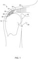
- Figure 1 shows a cross-sectional view of a shoulder 10 including an example implant 12.
- Shoulder 10 further shows a head 14 of humerus 16 mating with a glenoid fossa 18 of scapula 20.
- the glenoid fossa 18 comprises a shallow depression in scapula 20.
- a supraspinatus tendon 22 is also shown. These muscles (along with others) control the movement of humerus 16 relative to scapula 20.
- a distal tendon 24 of supraspinatus tendon 22 meets humerus 16 at an insertion point 26.
- tendon 24 includes a damaged portion 28 located near insertion point 26.
- Damaged portion 28 includes a tear 30 extending partially through tendon 24.
- Tear 30 may be referred to as a partial thickness tear.
- the depicted partial thickness tear 30 is on the bursal side of the tendon, however, the tear may also be on the opposite or articular side of the tendon 24 and/or may include internal tears to the tendon 24 not visible on either surface.
- Figure 1 further illustrates that the tendon repair implant 12 has been placed over the partial thickness tear 30.
- the tendon repair implant 12 is placed on the bursal side of the tendon regardless of whether the tear is on the bursal side, articular side or within the tendon. Further, the tendon repair implant 12 may overlay multiple tears.
- delivery of an implant 12 may require a physician to create an incision in the patient sufficient to access the target implant site.
- the physician may insert an implant delivery system through the access site and position the distal end of the implant delivery system adjacent the target implant site. The physician may then manipulate the implant delivery system to deploy an implant out of a delivery sheath adjacent the target implant site.
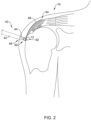
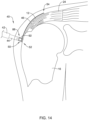
- Figure 2 provides a perspective view of an implant delivery system 40 extending through the shoulder 10 of a patient.
- Figure 2 shows implant delivery system 40 deployed adjacent a target site (e.g., a tear in the supraspinatus tendon).
- implant delivery system 40 comprises a sheath member 42 (e.g., a cannula) including a proximal portion (not shown), a distal portion 48 and a lumen extending within at least a portion of cannula 42.
- implant delivery system 40 may include a delivery shaft 44 extending within the lumen of sheath member 42 and longitudinally movable relative thereto.
- Delivery shaft 44 may include a proximal portion (not shown) extending out of the proximal portion of sheath member 42 and/or otherwise manipulatable relative to sheath member 42 by a user. Additionally, in some examples the proximal portion of delivery shaft 44 and/or sheath member 44 may be coupled to a handle member (not shown). The handle member may be utilized to manipulate delivery shaft 44. For example, the handle member may be utilized to impart a rotational force to delivery shaft 44.
- delivery shaft 44 may include a distal portion 50 extending out of the distal portion 48 of sheath member 42. Further, delivery shaft 44 may include a lumen extending therein. The lumen of delivery shaft 44 may extend along a portion or the entire length delivery shaft 44 (e.g., from distal portion 50 to the proximal portion of delivery shaft 44).
- Delivery system 40 may further include a detachable frame member 46 attached to the distal portion 50 of the delivery shaft 44.
- detachable frame 46 may be attached to an implant 12 (e.g., a sheet-like implant).
- implant 12 e.g., a sheet-like implant
- the combined structure including frame 46 and implant 12 may be defined as having a proximal end 52 and a distal end 54 as illustrated in Figure 2 .
- a clinician may orient the frame 46 and implant 12 (for example, via a handle member attached to a proximal portion of the delivery shaft 44) such that the proximal portion 52 may be adjacent (e.g., overlaid) on a portion of the humerus (e.g., on the bone), while the distal portion 54 of the frame 46 and implant 12 may overlay the tendon 24.
- delivery of implant delivery system 40 may include the insertion of delivery sheath 42 through an access site (e.g., incision) and advancement to a target site.
- a clinician may deploy the detachable frame 46 in combination with the implant 12 out of the lumen located within and along the distal portion 48 of the delivery sheath 42, such as by retracting delivery sheath 42 relative to delivery shaft 44 and frame 46, and positioning implant 12 and frame 46 over the target site.
- the detachable frame 46 and implant 12 combination Prior to deployment, the detachable frame 46 and implant 12 combination may be contained (e.g., housed) within the lumen of delivery sheath 42 for subsequent deployment distally out distal opening of delivery sheath 42. As will be described in greater detail below, the combination of detachable frame 46 and implant 12 may wrap and/or fold upon itself such that it may be positioned within the lumen of the delivery sheath 42. Alternatively, detachable frame 46 and implant 12 may warp and/or fold around implant delivery shaft 44 while disposed within delivery sheath 42.
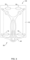
- FIG 3 shows an example detachable frame member 46 attached to example implant 12.
- detachable frame member 46 and implant 12 may have a proximal portion 52 which, for purposes of discussion herein, may be adjacent delivery shaft 44 and be configured to be positioned adjacent humerus 16.
- detachable frame member 46 and implant 12 may have a distal portion 54 which, for purposes of discussion herein, may extend away from deliver shaft 44 and be configured to be positioned adjacent tendon 24.
- Figure 3 further shows fastening regions 15 located at various positions within implant 12. As shown in Figure 3 , the fastening regions 15 are positioned at locations which are free from the structure of frame member 46. In other words, the shape of frame 46 may be designed to specifically permit fastening implant 12 to the anatomy at locations 15. For example, a clinician may staple implant 12 to the anatomy at locations 15.
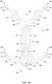
- Figure 4A shows an example detachable frame member 46.
- frame member 46 may include a body portion 56.
- body portion 56 may be understood to define a circular, ovular, or similar shaped framework from which other members may extend.
- body portion 56 of frame 46 may bear some resemblance to an elongated oval having a proximal portion 52 and a distal portion 54.
- Body portion 56 may include one or more apertures 74.
- frame 46 may include a head portion 58 positioned within and/or extending away from the proximal portion 52. Head portion 52 may include an aperture 60.
- detachable frame 46 may include one or more attachment arms 64 extending away from body portion 56.
- Each respective attachment arm 64 may include a proximal portion 66 and a distal portion 68.
- the proximal portion 66 of each of the attachment arms 64 may be rigidly attached to body portion 56, while the distal portion 68 may be a free end of the attachment arm 64 spaced away from body portion 56.
- attachment arms 64 and head portion 58 may form a monolithic structure with body portion 56.
- body portion 56, head portion 58 and attachment arms 64 may be formed (e.g., machined, cut, shaped, stamped, laser-cut, etc.) as a unitary structure from a single piece of material.
- detachable frame 46 may be constructed using alternative materials and/or manufacturing methodologies.
- frame 46, or portions thereof may be constructed from a polymeric material, a ceramic material and/or other various materials.
- frame 46 may be manufactured via an injection molding or alternative polymer manufacturing methodologies.
- frame 46 may be formed through a 3-D printing process, if desired.
- attachment arms 64 may be made from a polymer material and combined with a central frame member constructed from a metal. Variations of combining different materials with different portions of frame 46 are contemplated.
- attachment arms 64 may include a variety of shapes.
- attachment arms 64 may include a bow and/or general curvilinear shape (such as that shown in the attachment arm 64 closest to head portion 58).
- an attachment arm 64 may include additional features, such as the circular portion 72 positioned along the attachment arm 64 (as shown in attachment arm 64 located farthest from head portion 58).
- the circular portion 72 may be designed to provide a "visual engagement marker" for which a user (e.g., clinician) may be able to engage a secondary medical device and manipulate the position of the frame 46 after initial deployment.
- a clinician may be able to engage a secondary medical device with circular portion 72 and thereafter manipulate the secondary medical device to alter the initial deployment position of frame 46.
- frame 46 may include a variety of shapes and/or geometric arrangements.
- frame 46 may include one or more stiffening members 62 extending throughout frame 46.
- stiffening members 62 may be arranged within frame 46 (e.g., within body portion 56) such that they create one or more apertures 74.
- the number, shape, configuration and/or arrangement of stiffening members 62 and/or apertures 74 may depend on the particular performance characteristics desired to be imparted to detachable frame 46.
- additional stiffening members 62 may be added to frame 46 to provide increased stiffness to frame 46.
- stiffening members 62 may take on particular geometries that increase stiffness or flexibility in a particular direction while decreasing stiffness or flexibility in a different direction, for example.
- Stiffening members 62 may be located (e.g., arranged) throughout frame 46 in a variety of configurations to provide additional stiffness and/or structural integrity to a particular frame shape. In other words, a wide variety of different shapes and/or arrangements of stiffening members 62 may be included within frame 46 in order to impart customized performance characteristics of frame 46. For example, in some instances, it may be desirable to transfer rotational forces placed on head portion 58 to attachment arms 64 positioned at the distal portion of frame 46. The addition of stiffening members 62 may allow transfer of those rotational forces throughout frame 46 (e.g., to the distal portion of frame 46) while minimizing the amount of force lost and/or dissipated throughout the frame due to undesirable flexing of the frame members.
- Figure 4B shows another example of the frame 46.
- frame 46 may include a geometric shape that is similar to that described with respect to frame 46 shown in Figure 4A .
- frame 46 may include stiffening members 62 extending and spaced in a different arrangement (as compared with the stiffening members 62 shown in Figure 4A ).
- the frame 46 shown in Figure 4B may include different apertures 74 created by the alternative arrangement of stiffening members 62.
- Figures 4A and 4B further illustrate that frame 46 may include one or more attachment apertures 70 located along a distal portion 68 of one or more attachment arms 64.
- Figures 4A / 4B show attachment apertures 70 positioned at a distal portion 68 of the attachment arms 64.
- attachment apertures 70 may be utilized to attach the frame 46 to an example implant 12.
- attachment apertures 70 may be located along another region of attachment arms 64, such as a proximal portion of attachment arms 64 proximate body portion 56. In other words, it is contemplated that one or more attachment arm apertures may be positioned along any portion of frame 46.
- Figure 4B shows two attachment apertures 70 positioned along a distal portion 68 of each of the attachment arms 64.
- the number of attachment apertures positioned along frame 46 may be 1, 2, 3, 4, 5, 6, 7, 8, 9, 10, 15, 20 or more.
- attachment arms 64 may be devoid of attachment apertures. In such instances, attachment arms 64 may include an alternative attachment structure for attaching to implant 12.
- frame 46 when combined with an example implant 12, frame 46 may be defined as having a first surface that faces away from the implant 12 when implant 12 is attached to frame 46 (e.g., a first surface that faces away from a target site in the body) and a second surface that faces the example implant 12 (e.g., a second surface that faces a target site in the body).
- attachment apertures 70 may extend from the first surface to the second surface.
- attachment apertures 70 may be defined as holes and/or openings that extend through the thickness of frame 46 from the first surface of the frame 46 that faces away from the implant 12 to the second surface of the frame 46 that faces toward the implant 12.
- attachment apertures 70 may be utilized to attach and/or couple frame 46 to an example implant 12.
- Figure 5A shows an example frame 46 attached to an example implant 12.
- Figure 5 shows example frame 46 attached to example implant 12 at the distal or free end of each of the four attachment arms 64, respectively. Attachment of free distal ends of attachment arms 64 to implant 12 may be made by any desired attachment mechanism.
- Figure 5B shows a detailed view of a portion of the proximal portion 54 of a frame 46 attached to an implant 12 in a configuration similar to that discussed above with respect to Figures 2-4 . Further, Figure 5B shows example attachment arm 64 including a distal portion 68. Three attachment apertures 70 are positioned along the distal portion 68 of the attachment arm 64. Additionally, Figure 5B shows an example attachment member (e.g. wire) 76 extending between and through one or more of the attachment apertures 70 located on the distal portion 68 of attachment arms 64.
- example attachment member e.g. wire
- Attachment members 76 may be one of several structures and/or techniques contemplated to attach example frame 46 to example implant 12. As shown in Figure 5B , attachment member 76 may be positioned, looped, wound and/or threaded through one or more attachment apertures 70 such that the member 76 is prevented from being pulled away from the distal portion 68 of attachment arm 64. In other words, winding attachment member 76 through one or more attachment apertures 70 may effectively affix attachment member 76 onto the attachment arm 64.
- attachment member 76 may be affixed to the distal portion 68 of attachment arms 64 (via attachment apertures 70, for example) without having either end of the attachment member 76 directly attached (e.g., welded, tied, etc.) to any structure (e.g., frame 46). In some instances, member 76 may be wrapped and/or looped through attachment apertures 70 one or more times to provide a friction fit and/or resistive tension to unraveling or unwinding as a withdrawal force is applied to attachment member 76.
- Figure 5B shows a single attachment member 76 extending between two attachment apertures 70, it is contemplated that attachment member 76 may extend and/or wrap between two or more attachment apertures 70.
- attachment member 76 may be woven (e.g., over-and-under) through three apertures 70 in order to lock member 76 to the distal end 68 of attachment arm 64.
- an attachment member e.g., wire, thread, cable, etc.
- an attachment member e.g., wire, thread, cable, etc.
- adhesives may be used alone or in combination with another attachment mechanism to attach frame 46 to implant 12.
- injection molding techniques may be employed to attach frame 46 to implant 12.
- combinations of the disclosed techniques may be used to attach frame 46 to implant 12.
- an attachment member 76 may be used in conjunction with an adhesive to attach frame 46 to implant 12 without having to wind attachment member 76 through attachment apertures 70.
- frame 46 may be able to be "detached" from implant 12.
- frame 46 may be configured to detach from implant 12 after implant 12 has been affixed to a target site in the body, such as with staples and/or sutures. Therefore, it can be appreciated that in some examples disclosed herein, frame member 46 may be temporarily attached to implant 12.
- frame member 46 may be coupled, affixed or attached to implant 12 while positioned within delivery sheath 42, deployed out of delivery sheath 42 and maneuvered into position relative to a target site.
- implant 12 may be rigidly affixed to the target site, such as stapled and/or sutured to bone and/or tendon tissue at the target site.
- frame 46 may be pulled away (e.g., detached) from implant 12 and removed from the body.
- Figure 5B shows an example attachment configuration which may allow frame 46 to detach from implant 12.
- Figure 5B shows attachment member 76 wound in a spiral pattern 80 along the surface of implant 12 facing a target site.
- attachment member 76 may form a spiral pattern 80 that remains in a plane substantially parallel to the plane of the surface of implant 12 which faces a target site.
- attachment member 76 may extend from the side of attachment arm 64 facing away from implant 12, through the combined thickness of the attachment arm 64 and implant 12, eventually exiting implant 12 on the surface of implant 12 facing a target site.
- the spiral pattern 80 shown in Figure 5B is one of a variety of configurations for which attachment member 76 may be wound in order to prevent frame 46 from prematurely releasing from implant 12.
- Attachment member 76 may have a first end secured to a free distal end of attachment arm 64 positioned on a first side of implant 12 and have a second end positioned on a second, opposite side of implant 12. In some instances, attachment member 76 may extend through implant 12 from the first side of implant 12 to the second side of implant 12. However, in other instances, attachment member 76 may extend around an edge of implant 12 from the first side of implant 12 to the second side of implant 12.
- the attachment member 76 may be configured to be detached from implant 12 upon application of a threshold level of force.
- the spiral pattern 80 shown in Figure 5B may provide frame 46 the ability to detach from implant 12 when a force greater than or equal to a threshold "pull-away force" is applied to frame 46.
- a clinician may apply a force to frame 46 (via a tether, for example) such that frame 46 is pulled away from implant 12.
- attachment members 76 e.g., spiral portion 80 of attachment member 76 shown in Figures 5B
- body e.g., thickness
- attachment members 76 may be unwound and pulled back through the "body” (e.g., thickness) of implant 12, thereby releasing frame 46 from implant 12.
- the attachment member 76 forming the spiral 80 shown in Figure 5B may unwind and pull back through implant 12.
- the threshold "pull-away" force for the frame 46 to release from implant 12 may be about 0.25 lb to 1.75 lb, or may be about 0.75 lb to about 1.25 lb, or may be about 1.0 lb.
- the threshold "pull-away" force to release each of the four attachment member 76 from implant 12 may be about 0.0625 lb to 0.4375 lb, or may be about 0.1875 lb to about 0.3125 lb, or may be about 0.25 lb.
- Figure 5C shows another example method to attach frame 46 to an example implant 12.
- attachment member 76 may include a spiral 81 positioned on the surface of the implant 12 which faces away from a target site (similar to spiral 80 shown in Figure 5B ).
- Figure 5C shows that attachment member 76 may include a second spiral 82 positioned on the surface of attachment arm 68 that faces away from implant 12.
- Figure 5C shows two spirals 81/82 formed at opposite ends of attachment member 76 and positioned on both the attachment arm 64 facing away from implant 12 (e.g., spiral 82 of Figure 5C ) and on the side of the implant 12 lying along a treatment site (e.g., spiral 81 of Figure 5C ).
- the configuration of spirals 81/82 may provide a frame 46 with a "releasable" connection to implant 12 similar to that discussed with respect to Figure 5B .
- Figure 6 shows example frame 46 coupled to example implant 12 via attachment members 76 as described above. Further, Figure 6 shows frame 46 in combination with implant 12 coupled to example implant delivery system 40. Similar to that discussed with respect to Figure 2 , implant delivery system 40 includes implant delivery shaft 44 extending through an example lumen 84 of an example delivery sheath 42.
- connection assembly 88 may include a first connection member 90 attached to the head portion 58 of frame 46 and a second connection member 92 attached to the distal end 50 of delivery shaft 44. While Figure 6 does not directly show first connection member 90 attached directly to second connection member 92, it can be appreciated that the first and second connection members 90/92 of connection assembly 88 may form a mating connection.
- first connection member 90 may form a male connection member while second connection member 92 may form a mating female connection member.
- second connection member 92 may include a cavity which is configured to extend over and allow first connection member 90 to be inserted therein.
- the first connection member 90 may be a female connection member
- second connection member 92 may be a mating male connection member.
- connection assembly 88 may be defined as a "quick release" connection assembly, or otherwise decoupling connection assembly. It is further contemplated that a variety of design configurations may be employed to engage/disengage (i.e., couple/decouple) the first and second connection members 90/92 from one another.
- first and second connection members 90/92 may be coupled via a threaded connection, friction fit, spring loaded connection, bayonet connection, movable collar or other actuation mechanism, or the like. Further, connection member 90/92 may be engaged/disengaged by an operator of the device.
- delivery shaft 44 may be attached (via connection assembly 88, for example) to the head portion 58 of frame member 46.
- connection assembly 88 may attach to head portion 58 via an aperture 60 (shown in Figure 3 ).
- first connection member 90 may be attached to the head portion 58 of frame member 46 via a variety of mechanical fastening means (e.g., injection molding, encapsulation, bonding, etc.).
- delivery system 40 may include a tether 96 coupled to frame 46.
- Figure 6 shows tether 96 attached to first connection member 90.
- tether 96 may be coupled directly or indirectly to frame 46 and/or any other suitable structure.
- tether 96 may be a rigid structure (e.g., rod) or it may be a non-rigid structure (e.g., a wire, cable, etc.).
- tether 96 may be long enough to extend from frame 46 positioned at the target site to a location exterior of the patient through insertion site (i.e., incision), such as through a lumen 86 of delivery shaft 44 and out of a proximal portion of the implant delivery system 40 (e.g., proximal portion of delivery shaft 44).
- tether 96 may extend from frame 46 outside of delivery shaft 44 and out of a proximal portion of the implant delivery system 40.
- the tether 96 may be utilized to withdraw the frame 46 out of the body after the implant 12 has been attached.
- a physician may insert implant delivery system 40 (including a delivery sheath 42, delivery shaft 44, frame 46 and implant 12) through an incision and position the distal end of the implant delivery system 40 adjacent a target implant site (e.g., torn tendon).
- a target implant site e.g., torn tendon
- the physician may manipulate the implant delivery shaft 44 to advance the implant (while attached to the detachable frame 46) out of the delivery sheath 42 adjacent the target implant site.
- the physician may retract delivery sheath 42 proximally relative to delivery shaft 44 and frame 46 and/or may advance delivery shaft 44 and frame 46 distally relative to delivery sheath 42.
- Figure 6 shows frame 46 and implant 12 deployed from the distal portion 48 of delivery sheath 42.
- frame 46 and implant 12 may have a substantially concave shape with respect to delivery sheath 42. It can be appreciated that the concave shape of frame member 46 and implant 12 may facilitate positioning the implant 12 along the generally rounded shape of the human shoulder.
- frame 46 and implant 12 when positioned in the delivery sheath 42 (e.g., prior to deployment) the frame 46 and implant 12 may be wrapped around the delivery shaft 44 in a convex configuration. Therefore, frame 46 and implant 12 may shift from a first convex configuration (while wrapped tightly around delivery shaft 44 within lumen 84 of delivery sheath 42) to a second concave configuration when advanced (e.g., deployed) out of sheath 42.
- frame 46 and implant 12 may be attached to the delivery shaft 44 via the connection assembly 88 when positioned within the lumen 84 of the delivery sheath 42.
- the frame 46 and implant 12 may wrap, or extend around, the delivery shaft 44.
- the position of the frame 46 and implant 12 may be in a convex configuration with respect to the distal end 50 of the delivery shaft 44.
- the frame 46 and implant 12 may "shift" from a convex configuration to a concave configuration (as viewed with respect to the distal end 50 of delivery shaft 44).
- Figure 7 illustrates another example detachable frame member 146 attached to an implant 112. It is contemplated that any of the frame members and/or implants disclosed herein may be utilized in conjunction with any of the delivery systems and/or delivery system features disclosed herein. Further, frame member 146 and/or implant 112 may be similar in form and functionality to other example frame members described herein. For example, detachable frame member 146 and implant 112 may have a proximal portion 152 which, for purposes of discussion herein, may be adjacent delivery shaft 44 (described above) and be configured to be positioned adjacent humerus 16 (shown in Figure 1 ). Further, detachable frame member 146 and implant 112 may have a distal portion 154 which, for purposes of discussion herein, may extend away from deliver shaft 44 (described above) and be configured to be positioned adjacent tendon 24 (shown in Figure 1 ).
- Figure 8 shows example detachable frame member 146.
- frame member 146 may include a central body portion 156.
- body portion 156 may be understood to define a circular, ovular, square, rectangular or similar shaped framework from which other members may extend.
- body portion 156 of frame 146 may bear some resemblance to an elongated rectangle having a proximal portion 152 and a distal portion 154.
- Body portion 156 may include one or more apertures 174.
- frame 146 may include a head portion 158 positioned within and/or extending away from the body portion 156. Head portion 158 may include an aperture 160.
- detachable frame 146 may include one or more attachment arms 164 extending away from body portion 156.
- Each respective attachment arm 164 may include a proximal portion 166 and a distal portion 168.
- the proximal portion 166 of each of the attachment arms 164 may be rigidly attached to body portion 156, while the distal portion 168 may be a free end of the attachment arm 164 spaced away from body portion 156.
- attachment arms 164 and head portion 158 may form a monolithic structure with body portion 156.
- body portion 156, head portion 158 and attachment arms 164 may be formed (e.g., machined, cut, shaped, stamped, laser-cut, etc.) as a unitary structure from a single piece of material.
- detachable frame 146 may be constructed using alternative materials and/or manufacturing methodologies.
- frame 146, or portions thereof may be constructed from a polymeric material, a ceramic material and/or other various materials.
- frame 146 may be manufactured via an injection molding or alternative polymer manufacturing methodologies.
- frame 146 may be formed through a 3-D printing process, if desired.
- attachment arms 164 may be made from a polymer material and combined with a central frame member constructed from a metal. Variations of combining different materials with different portions of frame 146 are contemplated.
- attachment arms 164 may include a variety of shapes.
- attachment arms 164 may include a bow and/or general curvilinear shape (such as that shown in the attachment arm 164 closest to head portion 158).
- an attachment arm 164 may include additional features, such as the circular portion 172 positioned adjacent one or more attachment arms 164 (as shown adjacent two attachment arms 164 located farthest from head portion 158).
- the circular portion 172 may be designed to provide a "visual engagement marker" for which a user (e.g., clinician) may be able to engage a secondary medical device and manipulate the position of the frame 146 after initial deployment.
- a clinician may be able to engage a secondary medical device with circular portion 172 and thereafter manipulate the secondary medical device to alter the initial deployment position of frame 146.
- frame 146 may include a variety of shapes and/or geometric arrangements.
- frame 146 may include one or more stiffening members 162 extending throughout frame 146, such as throughout body portion 156.
- stiffening member 162 may be arranged within frame 146 (e.g., within body portion 156) such that it creates the one or more apertures 174.
- the number, shape, configuration and/or arrangement of stiffening members 162 and/or apertures 174 may depend on the particular performance characteristics desired to be imparted to detachable frame 146.
- stiffening members 162 may be added to frame 146 to provide increased stiffness to frame 146.
- stiffening members 162 may take on particular geometries that increase stiffness or flexibility in a particular direction and/or region while decreasing stiffness or flexibility in a different direction and/or region, for example.
- Stiffening members 162 may be located (e.g., arranged) throughout frame 146 in a variety of configurations to provide additional stiffness and/or structural integrity to a particular frame shape. In other words, a wide variety of different shapes and/or arrangements of stiffening members 162 may be included within frame 146 to impart customized performance characteristics on frame 146. For example, in some instances it may be desirable to transfer rotational forces placed on head portion 158 to attachment arms 164 positioned at the distal portion 154 of frame 146.
- stiffening members 162 may transfer those rotational forces throughout frame 146 (e.g., to the distal portion 154 of frame 146) while minimizing the amount of force lost and/or dissipated throughout the frame 146 due to undesirable flexing of the frame members.
- Figure 8 further illustrates that frame 146 may include an extension member 180 extending away from head portion 158 ("when viewed in the planar configuration shown in Figure 8 ).
- Extension member 180 may include a connection aperture 182 formed in a proximal region 184 of extension member 180.
- extension member 180 may include one or more extension arms 186 extending to a proximal portion of body portion 156.
- Extension arms 186 may be part of (e.g., a monolithic structure with) body portion 156.
- Figure 8 illustrates that extension arms 186 may include a curve.
- the shape of extension portion 180 may include a variety of shapes and/or configurations.
- Figure 8 further illustrates that frame 146 may include one or more attachment channels 170 located along a distal portion 168 of one or more attachment arms 164.
- Figure 8 shows attachment channels 170 positioned at a distal portion 168 of the attachment arms 164.
- attachment channels 170 may be utilized to attach the frame 146 to an example implant. While Figure 8 shows a single attachment channel 170 positioned along a distal portion 168 of each of the attachment arms 164, the illustrated number of attachment channels 170 is not intended to be limiting. In other words, it is contemplated that one or more attachment channels 170 may be positioned along any portion of frame 146.
- attachment channels 170 positioned along frame 146 may be 1, 2, 3, 4, 5, 6, 7, 8, 9, 10, 15, 20 or more.
- attachment arms 164 may be devoid of attachment channels 170.
- attachment arms 164 may include an alternative attachment structure for attaching to an implant.
- frame 146 When combined with an example implant, frame 146 may be defined as having a first surface that faces away from the implant when the implant is attached to frame 146 (e.g., a first surface that faces away from a target site in the body) and a second surface that faces the example implant (e.g., a second surface that faces a target site in the body).
- attachment channels 170 may extend from the first surface to the second surface.
- attachment channels 170 may be defined as openings that extend through the thickness of frame 146 from the first surface of the frame 146 that faces away from the implant to the second surface of the frame 146 that faces toward the implant.
- attachment channels 170 may be utilized to attach and/or couple frame 146 to an example implant.
- Figure 9A shows an example frame 146 attached to an example implant 112. Further, Figure 9A shows example frame 146 attached to example implant 112 at the distal or free end of each of the four attachment arms 164, respectively. Attachment of free distal ends of attachment arms 164 to implant 112 may be made by any desired attachment mechanism.
- Figure 9A further illustrates locking covers 198 positioned along the distal portion 168 of attachment arms 164.
- Locking cover 190 may be used in conjunction with attachment channels 170 to secure frame 146 to implant 112.
- Locking covers 198 may be constructed of a variety of materials.
- locking covers 198 may include a metal, a polymer or combinations thereof, for example.
- Figure 9B shows a detailed view of a portion of frame 146 attached to an implant 112 in a configuration similar to that discussed above with respect to Figures 7 and 8 .
- Figure 9B shows example attachment arm 164 including a distal portion 168. Attachment channels 170 are positioned along the distal portion 168 of the attachment arm 164.
- Figure 9B shows an example attachment member (e.g. wire) 176 extending between and/or through one or more of the attachment channels 170 located on the distal portion 168 of attachment arms 164.
- example attachment member e.g. wire
- Attachment member 176 may include a variety of structures and/or techniques designed to attach example frame 146 to example implant 112. As shown in Figure 9B , attachment member 176 may be inserted, looped, wound and/or threaded through one or more attachment channels 170 such that the attachment member 176 is prevented from being pulled away from the distal portion 168 of attachment arm 164. In other words, sliding, inserting and/or winding attachment member 176 through one or more attachment channels 170 may effectively affix attachment member 176 to attachment arm 164.
- attachment member 176 may be affixed to the distal portion 168 of attachment arms 164 (via attachment channels 170, for example) without having either end of the attachment member 176 permanently attached (e.g., welded, etc.) to any structure (e.g., frame 146). In some instances, attachment member 176 may be wrapped and/or looped through attachment channel 170 one or more times to provide a friction fit, interference fit, and/or resistive tension to unraveling or unwinding as a withdrawal force is applied to attachment member 176.
- attachment channel 170 may include an opening that extends through the thickness of attachment arm 164 (e.g., from a top surface to the bottom surface of attachment arm 164) and also that attachment channel 170 may extend through the sidewall 171 of attachment arm 164 such that attachment member 176 may be laterally inserted into and/or removed from attachment channel 170. Additionally, attachment channel 170 may include one or more widths along the length of attachment channel 170. For example, Figure 9B shows attachment channel 170 including a first width "X" which extends through sidewall 171 of attachment arm 164.
- Attachment channel 170 further includes a second width "Y.”
- width "X” may be narrower than width "Y.”
- width "X” may be sized such that it is slightly smaller than the width (e.g., diameter) of attachment member 176.
- the general shape of attachment channel 170 may be designed such that it may flex to an extent sufficient to permit attachment member to extend (e.g., be inserted) through the narrower portion of channel 170 defined by the width "X” and further advanced into the wider portion of channel 170 defined by width "Y.”
- Figure 9B further illustrates example detents 173.
- Detents may extend inwardly from the surface of sidewall 171.
- detents 173 may be designed to mate with a protrusion or tab extending from an inner surface of locking member 198.
- detents may be protrusions or protuberances extending from the surface of attachment arm 164 configured to engage and/or mate with a feature of locking cover 198.
- Figure 9B shows an example attachment configuration which may allow frame 146 to detach from implant 112.
- Figure 9B shows a portion of attachment member 176 wound in a spiral pattern 180 along the surface of implant 112 facing a target site.
- attachment member 176 may form a spiral pattern 180 that remains in a plane substantially parallel to the plane of the surface of implant 112 which faces a target site.
- attachment member 176 may extend from the side of attachment arm 164 facing away from implant 112, through the combined thickness of the attachment arm 164 (e.g., via attachment channel 170) and implant 112, eventually exiting implant 112 on the surface of implant 112 facing a target site.
- the attachment member 176 may include a retention portion, such as a spiral pattern 180 positioned on the opposite side of implant 112 from attachment arm 164 for coupling implant 112 to attachment arm 164.
- a retention portion such as a spiral pattern 180 positioned on the opposite side of implant 112 from attachment arm 164 for coupling implant 112 to attachment arm 164.
- the spiral pattern 180 shown in Figure 9B is one of a variety of configurations for which attachment member 176 may be wound in order to prevent frame 146 from prematurely releasing from implant 112.
- the portion of attachment member 176 forming the spiral 180 shown in Figure 9B may unwind and/or straighten and pull back through implant 112.
- attachment member 176 may have another shaped configuration positioned on the surface of implant 112 facing a target site, which may be straightened or release upon a sufficient removal force to pull back through implant 112.
- Figure 9B further shows locking member 198 positioned along the distal portion 168 of attachment arm 164.
- locking member 198 may be able to translate (e.g., slide) along attachment arm 164.
- Figure 9B shows the distal portion 168 of attachment arm 164 extending through at least a portion of locking member 198.
- locking member 198 may be a sleeve in which attachment arm 164 extends through lumen of sleeve.
- locking member 198 is designed such that there is sufficient clearance between the inner surface (e.g., the inner diameter) of locking member 198 and the outer surface (e.g., the outer diameter) of attachment arm 164 such that locking member 198 can slide along attachment arm 164.
- locking member 198 may slide along attachment arm 164 to a position in which locking member 198 covers attachment member 176 and/or attachment channel 170.
- Figure 9C shows locking member 198 positioned at the distal end 168 of the attachment arm 164.
- Figure 9C shows locking member 198 positioned over the top (e.g., covering) of attachment member 176 and attachment channel 170. It can be appreciated that when positioned over the top of the attachment member 176 and/or attachment channel 170, locking member 198 may pinch, hold, secure, and/or lock attachment member 176 to attachment arm 164, such as by securing or locking attachment member 176 in attachment channel 170.
- locking member 198 may resemble a "compression-like" fitting wherein locking member 198 is drawn over the top of attachment member 176, thereby compressing attachment member 176 onto attachment arm 164 such that attachment member 176 is prevented from separating from attachment arm 164.
- locking member 198 may lock in place via detents 173.
- a feature of locking member 198 engages detents 173 to inhibit or prevent locking member 198 from moving back to the unsecured position shown in Figure 9B .
- the locking member 198 may include one or more inwardly projecting tabs (not shown) designed to be inserted (e.g., mate with) detents 173. The combination of tabs and detents 173 are, therefore, designed to prevent locking member 198 from moving along attachment arm 164 after having been positioned over top the attachment member 176 and/or attachment channel 170.
- attachment member 176 may be passed through implant 112 with distal enlarged portion (e.g., spiral 180) positioned on a second surface of implant 112 facing away from frame 146. Portion of attachment member 176 extending from a first surface of implant 112 facing frame 146 may then be passed through attachment channel 170, such as passed laterally into attachment channel 170 and then bent, wound or otherwise manipulated around attachment arm 164. Locking member 198 may then be moved from a first, unsecured position, shown in Figure 9B to a second, secured position, shown in Figure 9C to secure attachment member 176 to attachment arm 164.
- Figure 9D shows a detailed view of a portion of another example frame 246 attached to implant 112 in a configuration similar to that discussed above with respect to Figures 9A-9C .
- Figure 9D shows example attachment arm 264 including a distal portion 268.
- An attachment channel 270 is positioned along the distal portion 268 of the attachment arm 264.
- Figure 9D shows an example attachment member (e.g. wire) 276 extending through the attachment channel 270 located on the distal portion 268 of attachment arm 264.
- Figure 9D further illustrates that the distal portion 268 of the attachment arm 264 may include one or more openings 273 that extend through the thickness of attachment arm 264 (e.g., from a top surface to the bottom surface of attachment arm 264) and also that attachment channel 270 may extend through the sidewall 271 of attachment arm 264 such that attachment member 276 may be laterally inserted into and/or removed from attachment channel 270.
- attachment member 276 may be looped through one or more openings 273 and implant 112 (the dashed line in Figure 9D depicts the attachment member 276 being looped through implant 112) in addition to being secured within attachment channel 270.
- Attachment member 276 may include a variety of structures and/or techniques designed to attach example frame 246 to example implant 112. As shown in Figure 9D , attachment member 276 may be inserted, looped, wound and/or threaded through one or more attachment channels 270 and/or openings 273 such that the attachment member 276 is prevented from being pulled away from the distal portion 268 of attachment arm 264. In other words, sliding, inserting and/or winding attachment member 276 through one or more attachment channels 270 and/or openings 273 may effectively affix attachment member 276 to attachment arm 264.
- attachment member 276 may be affixed to the distal portion 268 of attachment arms 264 (via attachment channels 270 and/or openings 273, for example) without having either end of the attachment member 276 permanently attached (e.g., welded, etc.) to any structure (e.g., frame 246).
- attachment member 276 may be wrapped and/or looped through attachment channel 270 and/or openings 273 one or more times to provide a friction fit, interference fit, and/or resistive tension to unraveling or unwinding as a withdrawal force is applied to attachment member 276.
- Figure 9E illustrates that in some examples, a locking member 298 may be molded directly onto and/or otherwise positioned on the distal portion 268 of attachment arm 264.
- Figure 9E shows an example locking member 298 positioned along the distal portion 268 of the attachment arm 264 whereby the locking member 298 covers at least a portion of the attachment member 276 and/or attachment channel 270.
- Figure 9E shows locking member 298 encircling (e.g., covering) attachment member 276 and attachment channel 270.
- the locking member 298 may pinch, hold, secure, and/or lock attachment member 276 to attachment arm 264, such as by securing or locking attachment member 276 in attachment channel 270 and/or openings 273.
- locking member 298 may compress attachment member 276 onto attachment arm 264 such that attachment member 276 is prevented from separating from attachment arm 264.
- any of the examples described herein may utilize a sliding locking member 198 (as shown and described in Figures 9A-9C ) and/or an over-molded locking member 298 (as shown and described in Figure 9E ).
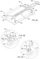
- Figure 10 illustrates a perspective view of frame 146 representing the configuration frame 146 would be in when inserted into the body.
- frame 146 shows frame 146 including extension member 180 coupled to both connection member 90 (similar in form and function to connection member 90 discussed above) and head portion 158.
- connection member 90 similar in form and function to connection member 90 discussed above
- head portion 158 may be coupled to connection member 90 and extend proximally therefrom.
- extension member 180 may curve upward and back on itself (e.g., upward and back toward the distal end 154 of frame 146).
- head portion 158 may extend upward and away from the body portion 156 of frame 146.
- connection member 90 may couple extension member 180 to head portion 158 via the apertures 182 and 160. In other words, connection member 90 may be inserted through both apertures 182 and 160, thereby securing extension member 180 to head portion 158. Additionally, Figure 10 shows a tack member 94 extending through a portion of frame 146. Tack member 94 will be described in greater detail below.
- Figure 10 illustrates that frame 146 may form a concave configuration when being inserted into the body. It can be appreciated that the concave shape of frame 146 may follow the contour of anatomy (e.g., shoulder) in which the example implant is to be secured.
- anatomy e.g., shoulder
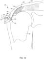
- Figure 11 illustrates a side view of frame 146 described in Figure 10 .
- Figure 11 illustrates the concave shape of frame 146.
- Figure 11 shows extension member 180 curving upward and back toward distal portion 154 of frame 146 as described above.
- Figure 11 shows head portion 158 extending upward and away from body portion 156 of frame 146.
- Extension member 180 and the head portion 158 are coupled to one another via connection member 90 extending through connection apertures 182, 1 60.
- connection apertures 182, 160 may be coaxial, with connection member 90 extending therethrough.
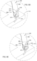
- Figure 11 shows tack member 94 extending through a portion of frame 146, such that the distal tip of tack member 94 penetrates through implant 112 to be positioned a distance below the lower surface (the surface of implant 112 opposite the frame 146) of implant 112.
- Figure 11 further illustrates the tether member 96 described above with respect to Figure 10 .
- the tether member 96 may be coupled to the tack member 94. While the above discussion describes the tether member 96 indirectly coupled to frame member 146 via the connection member 90, it is contemplated that in other instances the tether member 96 may be directly coupled to frame 146 (or other similar frame members described herein).
- the configuration of frame 146 shown in Figures 7-11 may provide both precise control and maneuverability to a clinician or other operator of the medical device.
- the geometry of the extension member 180 in combination with head portion 158 and connection member 90 may provide precise maneuverability of the distal portion 154 of frame 146.
- an operator may manipulate connection member 90 with a delivery shaft 44 (described above).
- the delivery shaft may be able to impart a downward force (e.g., a force directed toward a patient's shoulder) onto frame 146 via the combination of connection member 190, extension member 180 and head portion 158.
- the concave geometry of frame 146 may allow the distal portion of frame 146 to extend along the surface of the shoulder for which the implant 112 is to be positioned.
- the geometry of frame 146 shown in Figure 10 and Figure 11 may prevent the distal portion 154 of frame 146 (including attachment arms 164) from pulling up and away from the shoulder surface as a clinician manipulates frame 146 within the body.
- the geometry of frame 146 shown in Figures 10 and 11 may allow the distal portion 154 of frame 146 to be advanced toward the surface of the shoulder in which an implant 112 is to be positioned.
- frame 146 shown in Figure 11 may allow a clinician improved visibility of the frame 146 (e.g., the distal portion 154 of frame 146) during implantation of the medical device.
- a clinician may position a camera adjacent the implantation site.
- the clinician may utilize the camera to accurately maneuver and/or position an example implant into the patient.
- the camera my obscure and/or impede the visibility of all or a portion of the frame or implant (e.g., frame 146 and/or implant 112).
- connection member 90 and delivery sheath 44 coupled to connection member 90
- angle ⁇ may be measured from a line 155 that is orthogonal to a line 151 tangent to a point 153 generally positioned at the apex of a curve defined by body portion 156.
- Orienting connection member 90 such that it is directed away from the distal end 154 of frame 146 may increase the amount of space for which a camera may be placed during a procedure. In other words, a clinician may be able to maneuver the camera such that it provides improved visibility of all or a portion of the medical device being implanted (e.g., implant 112 via frame 146).
- any of the implant delivery systems described herein may include a tack member designed to "anchor" the delivery system in place prior to a clinician affixing implant 12 to the bone and/or tendon.
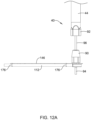
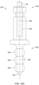
- Figure 12A illustrates a tack member 94 extending distally from the first connection member 90.
- tack member 94 may extend distally from first connection member 90 and be substantially perpendicular to implant 12 and/or frame 46.
- tack member 94 may extend generally parallel to the longitudinal axis of delivery sheath 42 and/or delivery shaft 44 with the frame 46 and implant 12 extending generally perpendicular to the longitudinal axis of delivery sheath 42 and/or delivery shaft 44.
- this configuration is not intended to be limiting. Rather, it is contemplated that tack member 94 may extend distally from the first connection member 90 and/or frame 46 at an oblique angle to the longitudinal axis of delivery sheath 42, delivery shaft 44, and/or frame 46.
- tack member 94 may resemble a cylindrical pin or rod extending away from frame 46.
- the tack member 94 may be designed to be rigid enough to be pounded and/or inserted into bone.
- a clinician may apply a force to a proximal portion of the implant delivery system 40 (e.g., delivery shaft 44) such that tack member 94 may be "hammered" into a body structure (e.g., bone).
- tack member 94 may include a tapered distal tip, which may be a sharpened or blunt tapered distal tip in some instances.
- tack member 94 may be stationary (e.g., fixed in place) relative to frame 46 and/or first connection member 90 of connection assembly 88.
- tack member 94 may extend distally from first connection member 90 and away from the surface of frame 46 which faces a target site.
- tack member 94 While the above discussion describes example tack member 94, the discussion relative thereto is not intended to be limiting. Rather, a variety of tack member designs and configurations are contemplated herein. Different tack members may be designed to impart specific insertion forces while the tack is being driven into a body structure (e.g., bone). Additionally, these tack designs may also provide specific release forces upon removing the tack from a body structure (e.g., bone).
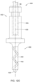
- Tack member 394 may include a proximal end region 340 and a distal end region 350.
- the distal end region 350 may include shaft member 352 and a tip member 354.
- the tip member 354. may be positioned at the distal end of the shaft member 352.
- the tack member 394 may include one or more radially enlarged portions positioned along the shaft member 352. Radially enlarged portions may be protuberances or lobes (e.g., continuous or discontinuous circumferential and/or helical rims, etc.) extending radially outward beyond the outer surface of the shaft member 352, for example.
- Figure 12B shows a first radially enlarged portion 356A and a second radially enlarged portion 356B positioned along the shaft member 352.
- the tack member 394 may include a single radially enlarged portion or more than two radially enlarged portions.
- the tack member 394 may include 1, 2, 3, 4, 5, 6, 7, 8 or more radially enlarged portions.
- the first radially enlarged portion 356A may be positioned adjacent tip member 354.
- the proximal end region 340 of the tack member 394 may include a vertical bore 355 extending inward from a proximal end surface 357 of the tack member 394.
- the vertical bore 355 may extend along the longitudinal axis 359 of the tack member 394.
- Figure 12B illustrates the tether member 96 (discussed with respect to Figure 12A ) extending within the vertical bore 355.
- the vertical bore 355 may include a profile which mirrors the shape of the tether member 96 extending within the vertical bore 355. It can further be appreciated that the tether member 96 may be attached to the tack member 394 via the vertical bore 355.
- the tether member 96 may be rigidly fixed to the tack member 394 within the vertical bore 355 via a variety of attachment techniques (e.g., welding, adhesive, crimping, swaging, etc.)
- the diameter of the tether member 96 is illustrated as being less than the diameter of the vertical bore 355, however, it is noted that upon securement of the tether member 96 within vertical bore 355, the tether member 96 may substantially occupy the bore 355.
- Figure 12B illustrates that the first radially enlarged portion 356A and the second radially enlarged portion 356B may be spaced longitudinally away from one another along the shaft member 352 with a portion of the shaft 352 positioned therebetween.
- Figure 12B shows the distance at which each of the first radially enlarged portion 356A and the second radially enlarged portion 356B are spaced away from the distal end 360 of the tip member 354.
- "X 1 " depicts the distance at which the first radially enlarged portion 356A is spaced away from the distal end 360 of the tip member 354.
- X 1 may be between 0.030 inches and 0.090 inches, or may be between 0.045 inches and 0.075 inches, or may be about 0.059 inches, for example.
- X 2 depicts the distance at which the second radially enlarged portion 356B is spaced away from the distal end 360 of the tip member 354.
- X 2 may be between 0.100 inches and 0.150 inches, or may be between 0.115 inches and 0.130 inches, or may be about 0.124 inches.
- first radially enlarged portion 356A and the second radially enlarged portion 356B may be adjacent one another.
- first radially enlarged portion 356A and the second radially enlarged portion 356B may be positioned directly adjacent one another.
- the tack member 394 may include more than two radially enlarged portions, some of which may be positioned away from other radially enlarged portions and/or some of which may be positioned directly adjacent other radially enlarged portions.
- first radially enlarged portion 356A and/or the second radially enlarged portion 356B may include a curved portion 357 having an outer surface which extends laterally away from the outer surface of the shaft member 352 located adjacent to the curved portion 357.
- the curved portion 357 of the radially enlarged portion 356 may have an outer diameter which is greater than the outer diameter of the shaft member 352 directly adjacent the curved portion 357.
- Figure 12B depicts the distance that curved portion 357 extends radially outward from the surface of the shaft member 352 as "X 3 .”
- X 3 may be between 0.001 inches and 0.015 inches, or may be between 0.005 inches and 0.010 inches, or may be about 0.006 inches.
- the distance that a first radially enlarged portion and a second radially enlarged portion extends away from the surface of the shaft member 352 may be different.
- a more proximal radially enlarged portion may extend radially outward from the shaft member 352 a greater distance or a lesser distance than a more distal radially enlarged portion.
- the distance that a first radially enlarged portion and a second radially enlarged portion extends away from the surface of the shaft member 352 may be substantially equivalent.
- the distance that curved portion 357 extends radially away from the surface of the shaft member 352 may correspond to the force required to retract the tack member 394 from a body structure into which the tack 394 may be inserted. It can further be appreciated that the shape, geometry, materials, etc. of the tack member 394 may be tailored to impart specific withdrawal forces from a body structure into which the tack member 394 may be inserted.
- the shaft member 352 may include a taper.
- the shaft member 352 may be tapered at an angle relative to the longitudinal axis 359 of the shaft member 352.
- angle of taper may be about 1 degree to about 5 degrees, for example.
- FIG 12C illustrates another example tack member 494.
- the tack member 494 may be similar in form and function to other tack members described herein.
- tack member 494 may include a proximal end region 440 and a distal end region 450.
- the distal end region 450 may include shaft member 452 and a tip member 454.
- the tip member 454 may be positioned at the distal end of the shaft member 452.
- the tack member 494 may further include the vertical bore 455.
- Figure 12C illustrates the tether member 96 extending within the vertical bore 455.
- the tether member 96 may be attached to the tack member 494 via the vertical bore 455 as described above.
- shaft member 452 may include one or more radially enlarged portions 462 positioned helically along the shaft member 452.
- the helical radially enlarged portion 462 may include a curved portion having an outer surface which extends radially outward beyond the outer surface of the shaft member 452.
- the helical radially enlarged portion 462 may extend longitudinally along the shaft member 452 in a helical fashion.
- Figure 12C shows a single helical radially enlarged portion extending along the surface of the shaft member 452, it is contemplated that the tack member 494 may include more than one helical radially enlarged portion 462.
- tack member 494 may include two helical radially enlarged portions helically arranged along the shaft member 452.
- first and second helical radially enlarged portions may extend around shaft member 452 in the same helical direction (e.g., a clockwise direction or a counterclockwise direction) along shaft member 452.
- first and second helical radially enlarged portions may extend around shaft member 452 in opposite directions (e.g., a first helical radially enlarged portion extending in a clockwise direction and a second helical radially enlarged portion may extend in a counterclockwise direction) along shaft member 452.
- FIG 12D illustrates another example tack member 594.
- the tack member 594 may be similar in form and function to other tack members described herein.
- tack member 594 may include a proximal end region 540 and a distal end region 550.
- the distal end region 550 may include shaft member 552 and a tip member 554.
- the tip member 554 may be positioned at the distal end of the shaft member 552.
- the tack member 594 may further include the vertical bore 555.
- Figure 12D illustrates the tether member 96 extending within the vertical bore 555.
- the tether member 96 may be attached to the tack member 594 via the vertical bore 555 as described above.
- tack member 594 may be formed as a composite structure including multiple components formed of dissimilar materials.
- tack member 594 may include shaft member 552 along with one or more fixation members 564 disposed along the shaft member 552 (depicted by the dashed line in Figure 12D ).
- the fixation members 564 may be constructed from materials different from the material used to construct the shaft member 552.
- the fixation members 564 may be formed from a material which is softer and/or more flexible than the material used to construct the shaft member 552, thus permitting the fixation members 564 to be radially compressible toward the longitudinal axis of the tack member 594.
- the fixation members 564 may include a polymeric material, composite material, or any other material with desirable compression/expansion characteristics, while the shaft member 552 may be formed of a metallic material, for example.
- the one or more fixation members 564 may surround or otherwise extend radially outward from the surface of the shaft member 552 with the shaft member 552 extending through the one or more fixation members 564.
- the one or more fixation members 564 may be positioned in one or more grooves or recesses formed in an outer surface of the shaft member 552.
- the fixation members 564 may be designed to provide a specific withdrawal force from a body structure into which the tack member may be inserted.
- the fixation members 564 may be designed from a material having a selected modulus which allows the material to be compressed while inserted into a body structure.
- this material may also permit the fixation members 564 to impart a specific radially-outward force against the body structure while inserted into the body structure. This radially-outward force may correspond to the force required to remove the tack member 594 from the body structure.
- radial compression of the fixation members 564 may be necessary for insertion of the tack member 594 into a body structure (e.g., bone) and removal of the tack member 594 from the body structure (e.g., bone).
- the materials, number, geometry, spacing, etc. utilized for the fixation members 564 may be tailored to provide a particular "release" force corresponding to a maximum threshold force that a clinician may want to impart on tack member 564 to remove it from the body structure.
- Tack member 694 may include a proximal end region 640 and a distal end region 650.
- the distal end region 650 may include shaft member 652 and a tip member 654.
- the tip member 654 may be positioned at the distal end of the shaft member 652.
- the tack member 694 may include one or more radially extending portions positioned along the shaft member 652. Radially extended portions may be protuberances (e.g., continuous or discontinuous circumferential and/or helical flats, etc.) extending radially outward beyond the outer surface of the shaft member 652, for example.
- Figure 12E shows a radially extending portion 653A positioned along the shaft member 652 and extending radially outward from the outer surface of shaft member 652. Additionally, Figure 12E shows a second radially extending portion 653B positioned adjacent to and/or extending from tip member 654.
- the tack member 694 may include a single radially extending portion or more than two radially extending portions.
- the tack member 694 may include 1, 2, 3, 4, 5, 6, 7, 8 or more radially extending portions.
- the first radially enlarged portion 652A may be positioned adjacent tip member 654.
- the proximal end region 640 of the tack member 694 may include a vertical bore 655 extending inward from a proximal end surface 657 of the tack member 694.
- the vertical bore 655 may extend along the longitudinal axis 659 of the tack member 694.
- Figure 12E illustrates the tether member 96 (discussed with respect to Figure 12A ) extending within the vertical bore 655.
- the vertical bore 655 may include a profile which mirrors the shape of the tether member 96 extending within the vertical bore 655. It can further be appreciated that the tether member 96 may be attached to the tack member 694 via the vertical bore 655.
- the tether member 96 may be rigidly fixed to the tack member 694 within the vertical bore 655 via a variety of attachment techniques (e.g., welding, adhesive, crimping, swaging, etc.)
- the diameter of the tether member 96 is illustrated as being less than the diameter of the vertical bore 655, however, it is noted that upon securement of the tether member 96 within vertical bore 655, the tether member 96 may substantially occupy the bore 655.
- Figure 12E illustrates that the first radially extending portion 653A and the second radially extending portion 653B may be spaced longitudinally away from one another along the shaft member 652 with a portion of the shaft 652 positioned therebetween.
- Figure 12E shows the distance at which each of the first radially extending portion 653A and the second radially enlarged portion 653B are spaced away from the distal end 660 of the tip member 654.
- "X 5 " depicts the distance at which the first radially extending portion 653A is spaced away from the distal end 660 of the tip member 654.
- X 5 may be between 0.090 inches and 0.175 inches, or may be between 0.115 inches and 0.150 inches, or may be about 0.127 inches, for example. Additionally, "X 4 " depicts the distance at which the second radially extending portion 653B is spaced away from the distal end 660 of the tip member 654. In some examples, X 4 may be between 0.025 inches and 0.100 inches, or may be between 0.050 inches and 0.075 inches, or may be about 0.062 inches.
- first radially extending portion 653A and the second radially enlarged portion 653B may be adjacent one another.
- first radially extending portion 653A and the second radially enlarged portion 653B may be positioned directly adjacent one another.
- the tack member 694 may include more than two radially extending portions, some of which may be positioned away from other radially extending portions and/or some of which may be positioned directly adjacent other radially extending portions.
- first radially enlarged portion 653A and/or the second radially enlarged portion 653B may include a rim or lip portion 651 having a radially extending tip 655 which extends laterally away from the outer surface of the shaft member 652.
- the radially extending portion 653A (including rim or lip portion 651) may have an outer diameter which is greater than the outer diameter of the shaft member 652.
- Figure 12E shows the diameter of the rim or lip portion 651 extending radially outward from the surface of the shaft member 652 as "D 2 " and the diameter of the shaft member 652 as "Dj.”
- D 2 may be between 0.035 inches and 0.100 inches, or may be between 0.050 inches and 0.075 inches, or may be about 0.070 inches.
- D 1 may be between 0.010 inches and 0.075 inches, or may be between 0.025 inches and 0.060 inches, or may be about 0.044 inches.
- the distance that a first radially extending portion 653A and second radially extending portion 653B extends away from the surface of the shaft member 652 may be different.
- a more proximal radially extending portion may extend radially outward from the shaft member 652 a greater distance or a lesser distance than a more distal radially extending portion.
- the distance that a first radially extending portion and a second radially extending portion extends away from the surface of the shaft member 652 may be substantially equivalent.
- the distance that radially extending portions 653A/653B extend radially away from the surface of the shaft member 652 may correspond to the force required to retract the tack member 694 from a body structure into which the tack 694 may be inserted. It can further be appreciated that the shape, geometry, materials, etc. of the tack member 694 may be tailored to impart specific withdrawal forces from a body structure into which the tack member 694 may be inserted.
- tack member 94 may be the first portion of delivery system 40 that exists the distal end 48 of delivery sheath 42 when the frame 46 and delivery shaft 44 are advanced out of the delivery sheath 42 upon deployment of the delivery system 40.
- the frame 46 to which implant 12 is attached
- a stationary tack member 94 may be fully housed within the lumen 84 of delivery sheath 48.
- the stationary tack member 94 may be driven directly into an adjacent structure (e.g., bone).
- frame member 46 and implant 12 may be positioned within delivery sheath 42 (depicted as dashed line) as shown in Figure 13A.
- Figure 13A shows frame member 46 (with implant 12) substantially aligned longitudinally with delivery shaft 44 and tack member 94.
- the distal portion 54 of frame 46 and implant 12 may be located distal of tack member 94 within delivery sheath 42, and thus the first portion of delivery system 40 that exits the distal end 48 of delivery sheath 42 when the frame 46 and delivery shaft 44 are advanced out of the delivery sheath 42 upon deployment of the delivery system 40.
- the frame member 146 and implant 112 may be positioned within delivery sheath 42 as shown in Figure 13B . Further, Figure 13B shows frame member 146 (and implant 112) substantially aligned longitudinally with delivery shaft 44 and tack member 94. In this example, the distal portion of frame 146 and implant 112 may be located distal of tack member 94 within delivery sheath 42, and thus the first portion of delivery system 140 that exits the distal end of delivery sheath 42 when the frame 146 and delivery shaft 44 are advanced out of the delivery sheath 42 upon deployment of the delivery system 40.
- Figure 13C illustrates that implant 112 may be rolled up and positioned between frame member 146 and the delivery sheath 42. Further, it can be appreciated that when positioned in delivery sheath 42 as illustrated in Figure 13B , implant 112 may wrap around frame member 146 with frame member 146 located radially inward of implant 112, and thereby extend along all or a portion of the inner surface of delivery sheath 42. Upon exiting the distal end of delivery sheath 42, implant 112 may unwrap to a configuration illustrated in Figure 10 and Figure 11 .
- tack member 94 may translate (e.g., slide, move, etc.) along a longitudinal axis within a lumen (not shown) of first connection member 90 of connection assembly 88.
- Figure 14 shows example deployment system 40 positioned adjacent an example target site.
- Figure 14 shows the proximal portion 52 of the frame 46 (along with implant 12) positioned adjacent the humeral head 16. In this position, the distal portion 54 of the frame 46 is positioned adjacent the tendon 24.
- Figure 14 further illustrates that the tack member 94 has not been advanced and/or extended out of the first connection member 90 of connection assembly 88 and driven into the humeral head.
- tack member 94 remains positioned within the connection assembly 88 (e.g., positioned within first connection member 90). However, in some examples contemplated herein, tack member 94 may be advanced out of the distal portion of delivery shaft 44 and/or connection assembly 88. In other words, the tack member 94 translates (e.g., slides, moves, etc.) relative to connection assembly 88 and advances away from the distal end 50 of delivery shaft 44.
- Figure 15 illustrates tack member 94 being advanced out of the distal portion 50 of delivery shaft 44 after delivery shaft 44 (along with frame 46 and implant 12) have been maneuvered and/or positioned adjacent an example target site.
- Figure 15 may depict delivery system 40 (discussed with respect to Figures 7 and 8 ) after the tack member 94 has been advanced out of the distal end 50 of the delivery shaft 44 (e.g., advanced distally of first connection member 90) and into the humeral head 16.
- tack member 94 may be advanced out of the distal end 50 of delivery shaft 44 via the application of a force at the proximal end of the delivery system 40 and/or actuation of an actuation mechanism to move tack member 94 relative to first connection member 90.
- a handle component may be utilized to generate a force to advance tack member 94 along a longitudinal axis of delivery shaft 44 and exit the distal end 50 of delivery shaft 44 distal of first connection member 90.
- FIG 15A illustrates the anchoring mechanism of the example tack member 394 (discussed above).
- the tack member 94 (of which tack member 394 shown in Figure 15A is a variation) may be anchored into the humeral head 16 of the humerus (a portion of which is shown in Figure 15A ).
- the humeral head 16 may include a cortical shell 17 covering a layer of soft bone 19.
- the cortical shell may be referred to as "hard" bone.
- Figure 15A further illustrates that in some instances it may be desirable to advance the tack member 394 through the layer of cortical bone such that the first radially enlarged portion 356A and/or the second radially enlarged portion 357A is positioned beneath the cortical bone layer.
- the tack member 394 may be advanced into the humeral head 16 such that the first radially enlarged portion 356A and/or the second radially enlarged portion 357A is positioned within the layer of soft bone, wherein the first radially enlarged portion 356A and/or the second radially enlarged portion 357A provide resistance to being pulled back through the underside of the cortical bone layer.
- first radially enlarged portion 356A and/or the second radially enlarged portion 357A are made of a compressible material
- the first radially enlarged portion 356A and/or the second radially enlarged portion 357A may be compressed as the first radially enlarged portion 356A and/or the second radially enlarged portion 357A are passed through the cortical shell 17.
- the amount of resistance provided by the first radially enlarged portion 356A and/or the second radially enlarged portion 357A may depend on the specific size and geometry of the first radially enlarged portion 356A and/or the second radially enlarged portion 357A.
- FIG. 16 illustrates removing delivery shaft 44 from the target site (depicted by the arrow in Figure 16 ) while the frame 46 and implant 12 remain anchored to the humeral head 16 via the tack member 94.
- delivery shaft 44 may be detached from frame 46 via uncoupling (e.g., detaching) second connection member 92 from first connection member 90.
- the bone e.g., humeral head
- tack member 94 may be abnormally soft or hard, and therefore, may require additional force to either maintain placement (e.g., if the bone is too soft) or to remove (e.g., if the bone is too hard). Therefore, a clinician may choose to reinsert and reengage shaft member 44 to frame 46 via re-coupling second connection member 92 to first connection member 90, such as after implant 12 has been attached to a target site via one or more bone and/or tendon staples, as described below.
- shaft member 44 may remain engaged to frame 46 while attaching implant 12 to a target site via one or more bone and/or tendon staples, as described below. The clinician may then be able to apply additional force to frame 46 and/or tack member 92 when attaching implant 12 to an example target site via one or more bone and/or tendon staples.
- delivery system 40 may include a tether 96 directly or indirectly coupled to frame 46.
- tether 96 may remain attached to frame 46 (e.g., via first connection member 90) and extend to a location exterior of the patient through insertion site (i.e., incision) with delivery shaft 44 detached from frame 46 and removed from insertion site (i.e., incision) while additional instruments are advanced through the insertion site and to the target site.
- Figure 17 shows a medical instrument 98 (e.g., implant stapler) positioned adjacent the proximal end 52 of the frame 46 and implant 12.
- a medical instrument 98 e.g., implant stapler
- tether 96 remains attached to frame 46 (e.g., via first connection member 90) and is positioned exterior of and alongside example medical instrument 98.
- the medical instrument 98 may be used to attach implant 12 to treatment site, such as with one or more, or a plurality of staples and/or sutures.
- implant 12 may be affixed to a target site after which the frame 46 may be detached (and removed) from both implant 12 and the target site.
- implant 12 may be attached to a target site via one or more bone and/or tendon staples.
- the staples may be applied to the target site via a stapling instrument (e.g., medical instrument 98).
- implant 12 it may be beneficial to affix implant 12 to the bone portion of the target site (e.g., humeral head 16) prior to affixing the implant to the tendon portion 24 of the target site.
- a clinician it may be beneficial for a clinician to orient and/or position the frame 46 and implant 12 in the location/arrangement shown in Figure 17 prior to affixing the implant to the target site.
- the implant is positioned such that the proximal portion 52 of the frame 46 and implant 12 are positioned adjacent the humeral head 16, while the distal portion 54 is positioned adjacent the tendon 24.
- a stapling instrument to first insert staples along the proximal portion 52 of the implant (e.g., the portion of the implant 12 positioned adjacent the bone) and into bone, followed by insertion of staples along the sides and distal portion of implant 12 and into tendon tissue.
- the tack member 94 may anchor the frame 46 and implant 12 in place (e.g., to the bone 16), thereby allowing a clinician to remove the delivery shaft 44 without fear that the frame/implant 46/12 combination will change position prior to the insertion of staples into the implant 12.
- the clinician may detach the frame 46 from the implant 12 (within the body) and remove it from the body via the insertion site.
- Figure 18 shows the detachment and removal of the frame 46 from the implant 12 (within the body) after the implant has been affixed (e.g., via staples) to the target site.
- the clinician may detach and remove frame 46 from the implant 12 and the body via application of a withdrawal force to the frame 46.
- the withdrawal force made be applied via the tether 96.
- a clinician may pull on the tether 96 (the proximal end of which may be positioned outside of the body), thereby applying a withdrawal force to frame 46. Once the withdrawal force reaches a threshold level (as discussed above), the frame 46 will detach from implant 12. Further withdrawal of the tether 96 may be continued to pull frame 46 out of the body via the insertion site.
Landscapes
- Health & Medical Sciences (AREA)
- Life Sciences & Earth Sciences (AREA)
- Surgery (AREA)
- Heart & Thoracic Surgery (AREA)
- Engineering & Computer Science (AREA)
- Biomedical Technology (AREA)
- Veterinary Medicine (AREA)
- Animal Behavior & Ethology (AREA)
- General Health & Medical Sciences (AREA)
- Public Health (AREA)
- Medical Informatics (AREA)
- Rheumatology (AREA)
- Molecular Biology (AREA)
- Nuclear Medicine, Radiotherapy & Molecular Imaging (AREA)
- Orthopedic Medicine & Surgery (AREA)
- Oral & Maxillofacial Surgery (AREA)
- Vascular Medicine (AREA)
- Transplantation (AREA)
- Cardiology (AREA)
- Rehabilitation Therapy (AREA)
- Prostheses (AREA)
- Surgical Instruments (AREA)
Claims (14)
- Système de pose d'implant (40), le système de pose d'implant comprenant:une tige de pose (44) incluant une partie proximale, une partie distale et une lumière s'étendant entre elles;un cadre (46, 146, 246) couplé de manière amovible à la partie distale de la tige de pose; etun élément de pointe (94, 394, 494, 594, 694) couplé au cadre;dans lequel l'élément de pointe inclut une tige (352, 452, 552, 652) ayant une surface circonférentielle caractérisé en ce que la pointe inclutune ou plusieurs protubérances s'étendant radialement en s'éloignant de la surface circonférentielle.
- Système de pose d'implant selon la revendication 1, dans lequel une partie d'extrémité distale de l'élément de pointe inclut une région effilée.
- Système de pose d'implant selon la revendication 2, dans lequel une partie d'extrémité proximale de l'élément de pointe inclut un alésage (355, 455, 555, 655) s'étendant le long d'un axe longitudinal (359, 459, 559, 659) de l'élément de pointe.
- Système de pose d'implant selon la revendication 3, dans lequel une partie d'extrémité distale d'un élément d'amarre (96) est fixée à l'intérieur de l'alésage de l'élément de pointe.
- Système de pose d'implant selon l'une quelconque des revendications 1 à 4, dans lequel les une ou plusieurs protubérances sont configurées pour ancrer l'élément de pointe sous une couche d'os.
- Système de pose d'implant selon la revendication 5, dans lequel les une ou plusieurs protubérances incluent un méplat circonférentiel continu s'étendant radialement vers l'extérieur au-delà de la surface circonférentielle de la tige de la pointe.
- Système de pose d'implant selon la revendication 5, dans lequel les une ou plusieurs protubérances incluent un rebord s'étendant radialement vers l'extérieur à partir de la surface circonférentielle de la tige de la pointe et ayant un diamètre entre 0,035 pouce (0,889 mm) et 0,100 pouce (2,54 mm).
- Système de pose d'implant selon les revendications 1 à 4, dans lequel la pointe comprend une pluralité de protubérances, dans lequel la pluralité de protubérances sont espacées les unes des autres le long de la tige de la pointe.
- Système de pose d'implant selon la revendication 8, dans lequel chacune de la pluralité de protubérances inclut un méplat circonférentiel continu s'étendant radialement vers l'extérieur au-delà de la surface circonférentielle de la tige de la pointe.
- Système de pose d'implant selon la revendication 8, dans lequel chacune de la pluralité de protubérances inclut un rebord s'étendant radialement vers l'extérieur à partir de la surface circonférentielle de la tige de la pointe et ayant un diamètre entre 0,035 pouce (0,889 mm) et 0,100 pouce (2,54 mm).
- Système de pose d'implant selon la revendication 10, dans lequel la tige de la pointe a un diamètre entre 0,010 pouce (0,254 mm) et 0,075 pouce (1,905 mm) entre la pluralité de protubérances.
- Système de pose d'implant selon l'une quelconque des revendications 1 à 4, dans lequel la tige de la pointe est formée à partir d'un premier matériau et un ou plusieurs éléments de fixation disposés le long de la tige de la pointe sont formés à partir d'un second matériau différent du premier matériau.
- Système de pose d'implant selon la revendication 12, dans lequel les un ou plusieurs éléments de fixation s'étendent radialement à distance de la surface circonférentielle de la tige de la pointe.
- Système de pose d'implant selon la revendication 1, dans lequel le cadre inclut:une partie corps (56, 156);une pluralité de bras d'attache (64, 164, 264) s'étendant à distance de la partie corps, où chaque bras d'attache inclut une ou plusieurs ouvertures s'étendant à travers une épaisseur du bras d'attache;un élément d'attache (76, 176, 276) enfilé à travers les une ou plusieurs ouvertures de chaque bras d'attache; etun élément de blocage (198, 298) moulé sur une partie distale de chaque bras d'attache et recouvrant l'élément d'attache associé et une ou plusieurs ouvertures pour fixer l'élément d'attache au bras d'attache.
Applications Claiming Priority (2)
| Application Number | Priority Date | Filing Date | Title |
|---|---|---|---|
| US201762595737P | 2017-12-07 | 2017-12-07 | |
| PCT/US2018/064215 WO2019113292A1 (fr) | 2017-12-07 | 2018-12-06 | Système de pose d'implant médical et procédés associés |
Publications (2)
| Publication Number | Publication Date |
|---|---|
| EP3720385A1 EP3720385A1 (fr) | 2020-10-14 |
| EP3720385B1 true EP3720385B1 (fr) | 2023-09-27 |
Family
ID=64744975
Family Applications (1)
| Application Number | Title | Priority Date | Filing Date |
|---|---|---|---|
| EP18822226.9A Active EP3720385B1 (fr) | 2017-12-07 | 2018-12-06 | Système de pose d'implant médical |
Country Status (6)
| Country | Link |
|---|---|
| US (3) | US10987210B2 (fr) |
| EP (1) | EP3720385B1 (fr) |
| JP (2) | JP7317826B2 (fr) |
| CN (1) | CN110225726A (fr) |
| AU (1) | AU2018380146B2 (fr) |
| WO (1) | WO2019113292A1 (fr) |
Families Citing this family (7)
| Publication number | Priority date | Publication date | Assignee | Title |
|---|---|---|---|---|
| US20180271641A1 (en) * | 2017-02-15 | 2018-09-27 | Worcester Polytechnic Institute | Surgical fastening device |
| CA3170127A1 (fr) | 2020-02-11 | 2021-08-19 | Embody, Inc. | Dispositif d'ancrage chirurgical, dispositif de deploiement et methode d'utilisation |
| CN115297805A (zh) | 2020-02-11 | 2022-11-04 | 恩博迪股份有限公司 | 植入物输送装置 |
| WO2021163317A1 (fr) | 2020-02-11 | 2021-08-19 | Embody, Inc. | Canule chirurgicale avec joint de pression amovible |
| WO2022132634A1 (fr) * | 2020-12-16 | 2022-06-23 | Smith & Nephew, Inc. | Système de pose d'implant médical et méthodes associées |
| WO2022235683A1 (fr) * | 2021-05-04 | 2022-11-10 | Smith & Nephew, Inc. | Système de pose d'implant médical |
| US20240138868A1 (en) | 2022-10-28 | 2024-05-02 | Expand Medical Ltd. | Implant delivery device |
Family Cites Families (475)
| Publication number | Priority date | Publication date | Assignee | Title |
|---|---|---|---|---|
| US511238A (en) | 1893-12-19 | Half to alfred brown | ||
| US3123077A (en) | 1964-03-03 | Surgical suture | ||
| US765793A (en) | 1903-09-16 | 1904-07-26 | John F Ruckel | Surgical bridge. |
| US1728316A (en) | 1927-07-02 | 1929-09-17 | Kirurgiska Instr Fabriks Aktie | Wound clasp |
| US1868100A (en) | 1929-01-19 | 1932-07-19 | Bella Goodstein | Staple and method of driving the same |
| US1855546A (en) | 1931-04-28 | 1932-04-26 | Norman W File | Surgical appliance |
| US1910688A (en) | 1931-08-03 | 1933-05-23 | Bella Goodstein | Staple |
| US1940351A (en) | 1933-03-22 | 1933-12-19 | Dougald T Mckinnon | Surgical instrument |
| US2075508A (en) | 1934-07-18 | 1937-03-30 | Edward W Davidson | Suture retainer |
| US2034785A (en) | 1935-07-12 | 1936-03-24 | Wappler Frederick Charles | Endoscopic forceps |
| US2154688A (en) | 1936-02-10 | 1939-04-18 | Matthews W N Corp | Fuse |
| US2199025A (en) | 1936-06-08 | 1940-04-30 | Carl E Conn | Means and method of closing surgical incisions |
| US2158242A (en) | 1936-10-08 | 1939-05-16 | Boston Wire Stitcher Co | Staple for blind stitching |
| US2131321A (en) | 1937-10-11 | 1938-09-27 | Hart Wilber | Ligator |
| US2201610A (en) | 1938-05-20 | 1940-05-21 | Jr James C Dawson | Wound clip |
| US2254620A (en) | 1939-11-14 | 1941-09-02 | George I Miller | Clip |
| US2283814A (en) | 1940-07-29 | 1942-05-19 | Bocji Corp | Staple and method of stapling |
| US2277931A (en) | 1941-07-03 | 1942-03-31 | Boston Wire Stitcher Co | Staple |
| US2316297A (en) | 1943-01-15 | 1943-04-13 | Beverly A Southerland | Surgical instrument |
| US2421193A (en) | 1943-08-02 | 1947-05-27 | Cleveland Clinic Foundation | Surgical dressing |
| US2571813A (en) | 1950-08-17 | 1951-10-16 | Clarence L Austin | Hog ringer |
| US2630316A (en) | 1950-09-01 | 1953-03-03 | Edwin E Foster | Constant compression spring |
| US2910067A (en) | 1952-10-13 | 1959-10-27 | Technical Oil Tool Corp | Wound clip and extractor therefor |
| US2684070A (en) | 1953-03-23 | 1954-07-20 | Walter L Kelsey | Surgical clip |
| US2744251A (en) | 1953-06-04 | 1956-05-08 | Vollmer Leonhard | Automatic inserter for suturing clips |
| US2817339A (en) | 1953-08-10 | 1957-12-24 | Norman M Sullivan | Rigid fascial suture |
| US2825162A (en) | 1954-01-18 | 1958-03-04 | Dennison Mfg Co | String tag attachment device |
| US2881762A (en) | 1955-02-09 | 1959-04-14 | Robert J Lowrie | Surgical staple and stapler |
| US2790341A (en) | 1956-04-17 | 1957-04-30 | Francis J Keep | Split shot pliers and dispenser |
| US3077812A (en) | 1958-01-27 | 1963-02-19 | Josef Kihlberg | Staple |
| US3068870A (en) | 1960-03-18 | 1962-12-18 | Levin Abraham | Wound clip |
| US3209754A (en) | 1961-08-10 | 1965-10-05 | Ernest C Wood | Surgical clip |
| US3103666A (en) | 1961-12-28 | 1963-09-17 | Dennison Mfg Co | Tag attaching apparatus |
| US3221746A (en) | 1963-01-25 | 1965-12-07 | Noble John William | Surgical connecting device |
| US3527223A (en) | 1967-09-01 | 1970-09-08 | Melvin Shein | Ear stud and hollow piercer for insertion thereof |
| US3470834A (en) | 1968-03-08 | 1969-10-07 | Dennison Mfg Co | Fastener attaching device |
| US3577837A (en) | 1968-04-30 | 1971-05-11 | Karl F Bader Jr | Subdermal tendon implant |
| US3570497A (en) | 1969-01-16 | 1971-03-16 | Gerald M Lemole | Suture apparatus and methods |
| US3579831A (en) | 1969-03-05 | 1971-05-25 | Irving J Stevens | Bone implant |
| US3643851A (en) | 1969-08-25 | 1972-02-22 | United States Surgical Corp | Skin stapler |
| US3716058A (en) | 1970-07-17 | 1973-02-13 | Atlanta Res Inst | Barbed suture |
| US3687138A (en) | 1970-08-17 | 1972-08-29 | Robert K Jarvik | Repeating ligature gun |
| US3837555A (en) | 1970-12-14 | 1974-09-24 | Surgical Corp | Powering instrument for stapling skin and fascia |
| US3717294A (en) | 1970-12-14 | 1973-02-20 | Surgical Corp | Cartridge and powering instrument for stapling skin and fascia |
| US3757629A (en) | 1971-05-10 | 1973-09-11 | R Schneider | Resilient plastic staple |
| US3777538A (en) | 1972-03-15 | 1973-12-11 | Weck & Co Edward | Surgical clip applicator |
| US3875648A (en) | 1973-04-04 | 1975-04-08 | Dennison Mfg Co | Fastener attachment apparatus and method |
| US3845772A (en) | 1973-09-17 | 1974-11-05 | D Smith | Retention suture device and method |
| US3976079A (en) | 1974-08-01 | 1976-08-24 | Samuels Peter B | Securing devices for sutures |
| US3960147A (en) | 1975-03-10 | 1976-06-01 | Murray William M | Compression bone staples and methods of compressing bone segments |
| US4014492A (en) | 1975-06-11 | 1977-03-29 | Senco Products, Inc. | Surgical staple |
| US4127227A (en) | 1976-10-08 | 1978-11-28 | United States Surgical Corporation | Wide fascia staple cartridge |
| US4259959A (en) | 1978-12-20 | 1981-04-07 | Walker Wesley W | Suturing element |
| US4263903A (en) | 1979-01-08 | 1981-04-28 | Richards Manufacturing Co., Inc. | Medical staple means |
| US4265226A (en) | 1979-03-23 | 1981-05-05 | Cassimally K A I | Incision closing method |
| US4317451A (en) | 1980-02-19 | 1982-03-02 | Ethicon, Inc. | Plastic surgical staple |
| GB2084468B (en) | 1980-09-25 | 1984-06-06 | South African Inventions | Surgical implant |
| US4526174A (en) | 1981-03-27 | 1985-07-02 | Minnesota Mining And Manufacturing Company | Staple and cartridge for use in a tissue stapling device and a tissue closing method |
| US4400833A (en) | 1981-06-10 | 1983-08-30 | Kurland Kenneth Z | Means and method of implanting bioprosthetics |
| US4485816A (en) | 1981-06-25 | 1984-12-04 | Alchemia | Shape-memory surgical staple apparatus and method for use in surgical suturing |
| US4809695A (en) | 1981-10-21 | 1989-03-07 | Owen M. Gwathmey | Suturing assembly and method |
| US4422567A (en) | 1981-11-17 | 1983-12-27 | Haynes Taylor H | Medical suturing device |
| US4480641A (en) | 1982-02-05 | 1984-11-06 | Ethicon, Inc. | Tip configuration for a ligating clip applier |
| US4509518A (en) | 1982-02-17 | 1985-04-09 | United States Surgical Corporation | Apparatus for applying surgical clips |
| US4454875A (en) | 1982-04-15 | 1984-06-19 | Techmedica, Inc. | Osteal medical staple |
| US5417691A (en) | 1982-05-20 | 1995-05-23 | Hayhurst; John O. | Apparatus and method for manipulating and anchoring tissue |
| US5601557A (en) | 1982-05-20 | 1997-02-11 | Hayhurst; John O. | Anchoring and manipulating tissue |
| US4741330A (en) | 1983-05-19 | 1988-05-03 | Hayhurst John O | Method and apparatus for anchoring and manipulating cartilage |
| US4595007A (en) | 1983-03-14 | 1986-06-17 | Ethicon, Inc. | Split ring type tissue fastener |
| US4570623A (en) | 1983-06-02 | 1986-02-18 | Pfizer Hospital Products Group Inc. | Arched bridge staple |
| US4627437A (en) | 1983-06-20 | 1986-12-09 | Ethicon, Inc. | Method of applying a fastener to tissue with a pair of hollow needles |
| US4582237A (en) | 1983-08-26 | 1986-04-15 | Anthony Storace | Surgical stapling system, apparatus and staple |
| US4549545A (en) | 1984-03-05 | 1985-10-29 | Ethicon Inc. | Segmented polyurethane surgical buttressing pledgets |
| US4635637A (en) | 1984-03-29 | 1987-01-13 | Schreiber Saul N | Surgical suture |
| WO1985005025A1 (fr) | 1984-05-07 | 1985-11-21 | Puchy David P W | Agrafeuse chirurgicale a degre variable de fermeture des agrafes |
| US4696300A (en) | 1985-04-11 | 1987-09-29 | Dennison Manufacturing Company | Fastener for joining materials |
| US4632100A (en) | 1985-08-29 | 1986-12-30 | Marlowe E. Goble | Suture anchor assembly |
| US4669473A (en) | 1985-09-06 | 1987-06-02 | Acufex Microsurgical, Inc. | Surgical fastener |
| USRE34021E (en) | 1985-11-18 | 1992-08-04 | Abbott Laboratories | Percutaneous fixation of hollow organs |
| US4738255A (en) | 1986-04-07 | 1988-04-19 | Biotron Labs, Inc. | Suture anchor system |
| US4884572A (en) | 1986-05-20 | 1989-12-05 | Concept, Inc. | Tack and applicator for treating torn bodily material in vivo |
| GB8620560D0 (en) | 1986-08-23 | 1986-10-01 | Femcare Ltd | Applicator |
| US4762260A (en) | 1986-09-11 | 1988-08-09 | Ophthalmic Ventures Limited Partnership | Surgical microstapler |
| US4719917A (en) | 1987-02-17 | 1988-01-19 | Minnesota Mining And Manufacturing Company | Surgical staple |
| US4799495A (en) | 1987-03-20 | 1989-01-24 | National Standard Company | Localization needle assembly |
| US5174295A (en) | 1987-04-10 | 1992-12-29 | Cardiometrics, Inc. | Apparatus, system and method for measuring spatial average velocity and/or volumetric flow of blood in a vessel and screw joint for use therewith |
| US4898156A (en) | 1987-05-18 | 1990-02-06 | Mitek Surgical Products, Inc. | Suture anchor |
| DE3722538A1 (de) | 1987-07-08 | 1989-01-19 | Wasserstein Isidor | Vorrichtung zur fixierung von knochensegmenten |
| US5261914A (en) * | 1987-09-02 | 1993-11-16 | Russell Warren | Surgical fastener |
| US4887601A (en) | 1987-11-06 | 1989-12-19 | Ophthalmic Ventures Limited Partnership | Adjustable surgical staple and method of using the same |
| US4968315A (en) | 1987-12-15 | 1990-11-06 | Mitek Surgical Products, Inc. | Suture anchor and suture anchor installation tool |
| CA2004658C (fr) | 1988-06-03 | 1995-10-10 | Michael A. Oberlander | Clip arthroscopique et outil d'insertion |
| EP0703757B1 (fr) | 1988-06-13 | 2003-08-27 | Karlin Technology, Inc. | Appareil d'insertion d'implants spinaux |
| US4924866A (en) | 1988-10-26 | 1990-05-15 | Inbae Yoon | Wound-closing device |
| EP0548998A1 (fr) | 1989-02-22 | 1993-06-30 | United States Surgical Corporation | Agrafe pour la peau |
| US4994073A (en) | 1989-02-22 | 1991-02-19 | United States Surgical Corp. | Skin fastener |
| US4930674A (en) | 1989-02-24 | 1990-06-05 | Abiomed, Inc. | Surgical stapler |
| US5522817A (en) | 1989-03-31 | 1996-06-04 | United States Surgical Corporation | Absorbable surgical fastener with bone penetrating elements |
| CA2013539C (fr) | 1989-03-31 | 1999-07-06 | Thomas W. Sander | Fixateur chirurgical absorbable avec elements penetrant le tissu osseux |
| US5062563A (en) | 1989-04-10 | 1991-11-05 | United States Surgical Corporation | Fascia stapler |
| US5059206A (en) | 1989-04-12 | 1991-10-22 | Winters Thomas F | Method and apparatus for repairing a tear in a knee meniscus |
| US5441508A (en) | 1989-04-27 | 1995-08-15 | Gazielly; Dominique | Reinforcement and supporting device for the rotator cuff of a shoulder joint of a person |
| US5053047A (en) | 1989-05-16 | 1991-10-01 | Inbae Yoon | Suture devices particularly useful in endoscopic surgery and methods of suturing |
| US6764500B1 (en) | 1989-05-29 | 2004-07-20 | Kensey Nash Corporation | Sealing device |
| US5129906A (en) | 1989-09-08 | 1992-07-14 | Linvatec Corporation | Bioabsorbable tack for joining bodily tissue and in vivo method and apparatus for deploying same |
| US5123913A (en) | 1989-11-27 | 1992-06-23 | Wilk Peter J | Suture device |
| US5015249A (en) | 1989-12-26 | 1991-05-14 | Nakao Naomi L | Endoscopic stapling device and method |
| US5156609A (en) | 1989-12-26 | 1992-10-20 | Nakao Naomi L | Endoscopic stapling device and method |
| US5002563A (en) | 1990-02-22 | 1991-03-26 | Raychem Corporation | Sutures utilizing shape memory alloys |
| US5013316A (en) | 1990-03-26 | 1991-05-07 | Marlowe Goble E | Soft tissue anchor system |
| WO1991015155A1 (fr) | 1990-04-02 | 1991-10-17 | Kanji Inoue | Procede pour refermer une ouverture de shunt au moyen d'un procede sans operateur |
| US5238004A (en) | 1990-04-10 | 1993-08-24 | Boston Scientific Corporation | High elongation linear elastic guidewire |
| US5102421A (en) | 1990-06-14 | 1992-04-07 | Wm. E. Anpach, III | Suture anchor and method of forming |
| US5041129A (en) | 1990-07-02 | 1991-08-20 | Acufex Microsurgical, Inc. | Slotted suture anchor and method of anchoring a suture |
| US5037422A (en) | 1990-07-02 | 1991-08-06 | Acufex Microsurgical, Inc. | Bone anchor and method of anchoring a suture to a bone |
| US5224946A (en) | 1990-07-02 | 1993-07-06 | American Cyanamid Company | Bone anchor and method of anchoring a suture to a bone |
| US5100417A (en) | 1990-07-13 | 1992-03-31 | American Cyanamid Company | Suture anchor and driver assembly |
| US5725529A (en) | 1990-09-25 | 1998-03-10 | Innovasive Devices, Inc. | Bone fastener |
| US5122155A (en) | 1990-10-11 | 1992-06-16 | Eberbach Mark A | Hernia repair apparatus and method of use |
| US5116357A (en) | 1990-10-11 | 1992-05-26 | Eberbach Mark A | Hernia plug and introducer apparatus |
| US5141515A (en) | 1990-10-11 | 1992-08-25 | Eberbach Mark A | Apparatus and methods for repairing hernias |
| US5203787A (en) | 1990-11-19 | 1993-04-20 | Biomet, Inc. | Suture retaining arrangement |
| WO1992013500A1 (fr) | 1991-02-08 | 1992-08-20 | Surgical Innovations, Inc. | Appareil et procede de reparation d'hernies inguinales |
| US5720753A (en) | 1991-03-22 | 1998-02-24 | United States Surgical Corporation | Orthopedic fastener |
| CA2063159C (fr) | 1991-03-22 | 1999-06-15 | Thomas W. Sander | Attache orthopedique |
| US5174487A (en) | 1991-04-04 | 1992-12-29 | Ethicon, Inc. | Endoscopic stapler and hernia repair mechanism |
| US5217472A (en) | 1991-05-07 | 1993-06-08 | United States Surgical Corporation | Surgical fastening device |
| US5269783A (en) | 1991-05-13 | 1993-12-14 | United States Surgical Corporation | Device and method for repairing torn tissue |
| US5251642A (en) | 1991-06-06 | 1993-10-12 | Baxter International Inc. | Tissue measuring and suturing device |
| CA2075080A1 (fr) | 1991-08-02 | 1993-02-03 | Ralph A. Dematteis | Methode et appareil de reparation des hernies par la parascopie |
| US5282829A (en) | 1991-08-15 | 1994-02-01 | United States Surgical Corporation | Hollow body implants |
| US5290217A (en) | 1991-10-10 | 1994-03-01 | Earl K. Sipes | Method and apparatus for hernia repair |
| AU662357B2 (en) | 1991-10-18 | 1995-08-31 | Ethicon Inc. | Adhesion barrier applicator |
| US5289963A (en) | 1991-10-18 | 1994-03-01 | United States Surgical Corporation | Apparatus and method for applying surgical staples to attach an object to body tissue |
| US5497933A (en) | 1991-10-18 | 1996-03-12 | United States Surgical Corporation | Apparatus and method for applying surgical staples to attach an object to body tissue |
| US5141520A (en) | 1991-10-29 | 1992-08-25 | Marlowe Goble E | Harpoon suture anchor |
| US5350400A (en) | 1991-10-30 | 1994-09-27 | American Cyanamid Company | Malleable, bioabsorbable, plastic staple; and method and apparatus for deforming such staple |
| US5176692A (en) | 1991-12-09 | 1993-01-05 | Wilk Peter J | Method and surgical instrument for repairing hernia |
| US5167665A (en) | 1991-12-31 | 1992-12-01 | Mckinney William W | Method of attaching objects to bone |
| US5156616A (en) | 1992-02-10 | 1992-10-20 | Meadows Bruce F | Apparatus and method for suture attachment |
| CA2090000A1 (fr) | 1992-02-24 | 1993-08-25 | H. Jonathan Tovey | Dispositif articule servant a positionner des implants chirurgicaux |
| CA2089999A1 (fr) | 1992-02-24 | 1993-08-25 | H. Jonathan Tovey | Dispositif souple servant a positionner des implants chirurgicaux |
| US5333624A (en) | 1992-02-24 | 1994-08-02 | United States Surgical Corporation | Surgical attaching apparatus |
| US5242457A (en) | 1992-05-08 | 1993-09-07 | Ethicon, Inc. | Surgical instrument and staples for applying purse string sutures |
| US5766246A (en) | 1992-05-20 | 1998-06-16 | C. R. Bard, Inc. | Implantable prosthesis and method and apparatus for loading and delivering an implantable prothesis |
| US5501695A (en) | 1992-05-27 | 1996-03-26 | The Anspach Effort, Inc. | Fastener for attaching objects to bones |
| US5176682A (en) | 1992-06-01 | 1993-01-05 | Chow James C Y | Surgical implement |
| US6312442B1 (en) | 1992-06-02 | 2001-11-06 | General Surgical Innovations, Inc. | Method for developing an anatomic space for laparoscopic hernia repair |
| US5797931A (en) | 1992-06-04 | 1998-08-25 | Olympus Optical Co., Ltd. | Tissue-fixing surgical instrument, tissue-fixing device, and method of fixing tissues |
| US5304187A (en) | 1992-06-30 | 1994-04-19 | United States Surgical Corporation | Surgical element deployment apparatus |
| US5269753A (en) | 1992-07-14 | 1993-12-14 | Wilk Peter J | Method for use in laparoscopic hernia repair |
| US5364408A (en) | 1992-09-04 | 1994-11-15 | Laurus Medical Corporation | Endoscopic suture system |
| CA2437777C (fr) | 1992-09-21 | 2006-11-28 | United States Surgical Corporation | Dispositif d'application d'une agrafe meniscale |
| US5464403A (en) | 1992-10-29 | 1995-11-07 | General Surgical Innovations, Inc. | Placement tool and method for laparoscopic hernia repair |
| IL103737A (en) | 1992-11-13 | 1997-02-18 | Technion Res & Dev Foundation | Stapler device particularly useful in medical suturing |
| US5622257A (en) | 1992-12-11 | 1997-04-22 | Avery Dennison Corporation | Fastener for attaching a button to a garment or like material and fastener clip including one or more of said fasteners |
| US5403326A (en) | 1993-02-01 | 1995-04-04 | The Regents Of The University Of California | Method for performing a gastric wrap of the esophagus for use in the treatment of esophageal reflux |
| US5380334A (en) | 1993-02-17 | 1995-01-10 | Smith & Nephew Dyonics, Inc. | Soft tissue anchors and systems for implantation |
| US5441502A (en) | 1993-02-17 | 1995-08-15 | Mitek Surgical Products, Inc. | System and method for re-attaching soft tissue to bone |
| US5342396A (en) | 1993-03-02 | 1994-08-30 | Cook Melvin S | Staples |
| US5354292A (en) | 1993-03-02 | 1994-10-11 | Braeuer Harry L | Surgical mesh introduce with bone screw applicator for the repair of an inguinal hernia |
| US5352229A (en) | 1993-05-12 | 1994-10-04 | Marlowe Goble E | Arbor press staple and washer and method for its use |
| US5505735A (en) | 1993-06-10 | 1996-04-09 | Mitek Surgical Products, Inc. | Surgical anchor and method for using the same |
| US5372604A (en) | 1993-06-18 | 1994-12-13 | Linvatec Corporation | Suture anchor for soft tissue fixation |
| CA2124996C (fr) | 1993-06-21 | 2006-01-31 | Thomas W. Sander | Applicateur de fixation orthopedique |
| US5500000A (en) | 1993-07-01 | 1996-03-19 | United States Surgical Corporation | Soft tissue repair system and method |
| US5478354A (en) | 1993-07-14 | 1995-12-26 | United States Surgical Corporation | Wound closing apparatus and method |
| CA2124651C (fr) | 1993-08-20 | 2004-09-28 | David T. Green | Appareil et methode pour mettre en place et ajuster un dispositif d'ancrage de structures internes |
| US5507754A (en) | 1993-08-20 | 1996-04-16 | United States Surgical Corporation | Apparatus and method for applying and adjusting an anchoring device |
| US5411522A (en) | 1993-08-25 | 1995-05-02 | Linvatec Corporation | Unitary anchor for soft tissue fixation |
| US5397332A (en) | 1993-09-02 | 1995-03-14 | Ethicon, Inc. | Surgical mesh applicator |
| ES2219643T3 (es) | 1993-09-17 | 2004-12-01 | F. Hoffmann-La Roche Ag | Aparato analitico con un dispositivo para la suspension de particulas y procedimiento para llevar a cabo la suspension. |
| US5560532A (en) | 1993-10-08 | 1996-10-01 | United States Surgical Corporation | Apparatus and method for applying surgical staples to body tissue |
| US5584835A (en) | 1993-10-18 | 1996-12-17 | Greenfield; Jon B. | Soft tissue to bone fixation device and method |
| US5545180A (en) | 1993-12-13 | 1996-08-13 | Ethicon, Inc. | Umbrella-shaped suture anchor device with actuating ring member |
| US5618314A (en) | 1993-12-13 | 1997-04-08 | Harwin; Steven F. | Suture anchor device |
| AU1011595A (en) | 1994-01-13 | 1995-07-20 | Ethicon Inc. | Spiral surgical tack |
| US5425490A (en) | 1994-01-18 | 1995-06-20 | Goble; E. Marlowe | Instrument with dual holding feature |
| US5417712A (en) | 1994-02-17 | 1995-05-23 | Mitek Surgical Products, Inc. | Bone anchor |
| US5486197A (en) | 1994-03-24 | 1996-01-23 | Ethicon, Inc. | Two-piece suture anchor with barbs |
| US5411523A (en) | 1994-04-11 | 1995-05-02 | Mitek Surgical Products, Inc. | Suture anchor and driver combination |
| US5582616A (en) | 1994-08-05 | 1996-12-10 | Origin Medsystems, Inc. | Surgical helical fastener with applicator |
| US5643321A (en) | 1994-11-10 | 1997-07-01 | Innovasive Devices | Suture anchor assembly and methods |
| US5649963A (en) | 1994-11-10 | 1997-07-22 | Innovasive Devices, Inc. | Suture anchor assembly and methods |
| IL111985A (en) | 1994-12-14 | 1999-04-11 | Medical Influence Technologies | Staple and thread assembly particularly for use in power-driven staplers for medical suturing |
| AU5027296A (en) | 1995-02-22 | 1996-09-11 | Kurt Ilgen | Device for the repair of hoof cracks |
| FR2731343B1 (fr) | 1995-03-08 | 1997-08-22 | De La Joliniere Jean H Bouquet | Dispositif de reperage de lesions suspectes du sein et appareil pour sa mise en place |
| US5919184A (en) | 1995-03-17 | 1999-07-06 | Tilton, Jr.; Eugene B. | Instrumentation for laparoscopic insertion and application of surgical sheet material |
| US7867222B1 (en) | 1995-03-17 | 2011-01-11 | Tilton Jr Eugene B | Instrumentation for endoscopic surgical insertion and application of liquid, gel and like material |
| US5503623A (en) | 1995-03-17 | 1996-04-02 | Tilton, Jr.; Eugene B. | Instrumentation for laparoscopic insertion and application of sheet like surgical material |
| US6245072B1 (en) | 1995-03-27 | 2001-06-12 | Sdgi Holdings, Inc. | Methods and instruments for interbody fusion |
| US6123727A (en) | 1995-05-01 | 2000-09-26 | Massachusetts Institute Of Technology | Tissue engineered tendons and ligaments |
| US5702215A (en) | 1995-06-05 | 1997-12-30 | Li Medical Technologies, Inc. | Retractable fixation device |
| US5569306A (en) | 1995-06-06 | 1996-10-29 | Thal; Raymond | Knotless suture anchor assembly |
| US5667513A (en) | 1995-06-07 | 1997-09-16 | Smith & Nephew Dyonics Inc. | Soft tissue anchor delivery apparatus |
| US5681342A (en) | 1995-08-17 | 1997-10-28 | Benchetrit; Salomon | Device and method for laparoscopic inguinal hernia repair |
| US5662683A (en) | 1995-08-22 | 1997-09-02 | Ortho Helix Limited | Open helical organic tissue anchor and method of facilitating healing |
| US5997552A (en) | 1995-10-20 | 1999-12-07 | United States Surgical Corporation | Meniscal fastener applying device |
| RU2193867C2 (ru) | 1995-12-13 | 2002-12-10 | Нюкомед Арцнаймиттель ГмбХ | Инструмент для наложения хирургического материала (варианты) |
| US5741282A (en) | 1996-01-22 | 1998-04-21 | The Anspach Effort, Inc. | Soft tissue fastener device |
| US5725541A (en) | 1996-01-22 | 1998-03-10 | The Anspach Effort, Inc. | Soft tissue fastener device |
| US5957953A (en) | 1996-02-16 | 1999-09-28 | Smith & Nephew, Inc. | Expandable suture anchor |
| US5885258A (en) | 1996-02-23 | 1999-03-23 | Memory Medical Systems, Inc. | Medical instrument with slotted memory metal tube |
| US5893856A (en) | 1996-06-12 | 1999-04-13 | Mitek Surgical Products, Inc. | Apparatus and method for binding a first layer of material to a second layer of material |
| US6117162A (en) | 1996-08-05 | 2000-09-12 | Arthrex, Inc. | Corkscrew suture anchor |
| WO1998007375A1 (fr) | 1996-08-22 | 1998-02-26 | The Trustees Of Columbia University | Dispositif d'agrafage endovasculaire flexible |
| US6984241B2 (en) | 1996-09-13 | 2006-01-10 | Tendon Technology, Ltd. | Apparatus and methods for tendon or ligament repair |
| US5830221A (en) | 1996-09-20 | 1998-11-03 | United States Surgical Corporation | Coil fastener applier |
| US5948000A (en) | 1996-10-03 | 1999-09-07 | United States Surgical Corporation | System for suture anchor placement |
| DE69727015T2 (de) | 1996-10-04 | 2004-11-25 | United States Surgical Corp., Norwalk | Vorrichtung zum Anbringen eines Gewebe-Befestigungselements |
| US6063088A (en) | 1997-03-24 | 2000-05-16 | United States Surgical Corporation | Method and instrumentation for implant insertion |
| FR2758975B1 (fr) | 1997-02-05 | 1999-04-30 | Ethnor | Materiel pour la fixation d'un tendon de muscle sur un os |
| US5782864A (en) | 1997-04-03 | 1998-07-21 | Mitek Surgical Products, Inc. | Knotless suture system and method |
| US5922026A (en) | 1997-05-01 | 1999-07-13 | Origin Medsystems, Inc. | Surgical method and prosthetic strip therefor |
| US6001110A (en) | 1997-06-20 | 1999-12-14 | Boston Scientific Corporation | Hemostatic clips |
| US6338737B1 (en) | 1997-07-17 | 2002-01-15 | Haviv Toledano | Flexible annular stapler for closed surgery of hollow organs |
| US5957939A (en) | 1997-07-31 | 1999-09-28 | Imagyn Medical Technologies, Inc. | Medical device for deploying surgical fabrics |
| US5885294A (en) | 1997-09-22 | 1999-03-23 | Ethicon, Inc. | Apparatus and method for anchoring a cord-like element to a workpiece |
| US5868762A (en) | 1997-09-25 | 1999-02-09 | Sub-Q, Inc. | Percutaneous hemostatic suturing device and method |
| US5947984A (en) | 1997-10-10 | 1999-09-07 | Ethicon Endo-Surger, Inc. | Ultrasonic clamp coagulator apparatus having force limiting clamping mechanism |
| DE19801219A1 (de) | 1998-01-15 | 1999-07-22 | Holger K Dr Essiger | Knochennagel |
| US6096074A (en) | 1998-01-27 | 2000-08-01 | United States Surgical | Stapling apparatus and method for heart valve replacement |
| FR2774277B1 (fr) | 1998-02-03 | 2000-06-30 | Cogent Sarl | Agrafe de fixation prothetique resorbable |
| US6592593B1 (en) | 1998-09-18 | 2003-07-15 | United States Surgical Corporation | Endovascular fastener applicator |
| CA2333121C (fr) | 1998-05-21 | 2006-07-25 | Christopher J. Walshe | Systeme de fixation des tissus |
| US6726704B1 (en) | 1998-05-29 | 2004-04-27 | By-Pass, Inc. | Advanced closure device |
| US7063711B1 (en) | 1998-05-29 | 2006-06-20 | By-Pass, Inc. | Vascular surgery |
| US6248112B1 (en) | 1998-09-30 | 2001-06-19 | C. R. Bard, Inc. | Implant delivery system |
| US6458092B1 (en) | 1998-09-30 | 2002-10-01 | C. R. Bard, Inc. | Vascular inducing implants |
| US6248108B1 (en) * | 1998-09-30 | 2001-06-19 | Bionx Implants Oy | Bioabsorbable surgical screw and washer system |
| US6099518A (en) | 1998-10-20 | 2000-08-08 | Boston Scientific Corporation | Needle herniorrhaphy devices |
| US6318616B1 (en) | 1998-10-23 | 2001-11-20 | United States Surgical | Surgical fastener applier |
| US6193731B1 (en) | 1998-10-27 | 2001-02-27 | Fziomed, Inc. | Laparoscopic insertion and deployment device |
| US6508803B1 (en) | 1998-11-06 | 2003-01-21 | Furukawa Techno Material Co., Ltd. | Niti-type medical guide wire and method of producing the same |
| US6482210B1 (en) | 1998-11-12 | 2002-11-19 | Orthopaedic Biosystems, Ltd., Inc. | Soft tissue/ligament to bone fixation device with inserter |
| AU5924099A (en) | 1998-12-31 | 2000-07-24 | Jeffrey E. Yeung | Tissue fastening devices and delivery means |
| EP1031321B1 (fr) | 1999-02-02 | 2008-01-09 | Arthrex Inc | Pointe bioabsorbable pour tissu avec tête de forme ovale |
| US7226469B2 (en) | 1999-02-02 | 2007-06-05 | Arthrex, Inc. | Insert molded suture anchor |
| US6387113B1 (en) | 1999-02-02 | 2002-05-14 | Biomet, Inc. | Method and apparatus for repairing a torn meniscus |
| US6315789B1 (en) | 1999-02-08 | 2001-11-13 | Andrew H. Cragg | Medical device anchoring system and method |
| US20020090725A1 (en) | 2000-11-17 | 2002-07-11 | Simpson David G. | Electroprocessed collagen |
| US6391333B1 (en) | 1999-04-14 | 2002-05-21 | Collagen Matrix, Inc. | Oriented biopolymeric membrane |
| US6325805B1 (en) | 1999-04-23 | 2001-12-04 | Sdgi Holdings, Inc. | Shape memory alloy staple |
| US6482178B1 (en) | 1999-05-21 | 2002-11-19 | Cook Urological Incorporated | Localization device with anchoring barbs |
| GB9912240D0 (en) | 1999-05-27 | 1999-07-28 | Smith & Nephew | Implantable medical devices |
| US8025199B2 (en) | 2004-02-23 | 2011-09-27 | Tyco Healthcare Group Lp | Surgical cutting and stapling device |
| US6964685B2 (en) | 1999-06-22 | 2005-11-15 | The Brigham And Women's Hospital, Inc. | Biologic replacement for fibrin clot |
| US20040059416A1 (en) | 1999-06-22 | 2004-03-25 | Murray Martha M. | Biologic replacement for fibrin clot |
| US6835200B2 (en) | 1999-06-22 | 2004-12-28 | Ndo Surgical. Inc. | Method and devices for tissue reconfiguration |
| US6494888B1 (en) | 1999-06-22 | 2002-12-17 | Ndo Surgical, Inc. | Tissue reconfiguration |
| US7416554B2 (en) | 2002-12-11 | 2008-08-26 | Usgi Medical Inc | Apparatus and methods for forming and securing gastrointestinal tissue folds |
| US7214232B2 (en) | 1999-07-23 | 2007-05-08 | Ethicon, Inc. | Graft fixation device |
| US6319252B1 (en) | 1999-07-23 | 2001-11-20 | Mcdevitt Dennis | System and method for attaching soft tissue to bone |
| US6179840B1 (en) | 1999-07-23 | 2001-01-30 | Ethicon, Inc. | Graft fixation device and method |
| US6436110B2 (en) | 1999-07-23 | 2002-08-20 | Ethicon, Inc. | Method of securing a graft using a graft fixation device |
| US7972337B2 (en) | 2005-12-28 | 2011-07-05 | Intrinsic Therapeutics, Inc. | Devices and methods for bone anchoring |
| US6554852B1 (en) | 1999-08-25 | 2003-04-29 | Michael A. Oberlander | Multi-anchor suture |
| US6322563B1 (en) | 1999-09-17 | 2001-11-27 | Genzyme Corporation | Small tissue and membrane fixation apparatus and methods for use thereof |
| US6231561B1 (en) | 1999-09-20 | 2001-05-15 | Appriva Medical, Inc. | Method and apparatus for closing a body lumen |
| US6428548B1 (en) | 1999-11-18 | 2002-08-06 | Russell F. Durgin | Apparatus and method for compressing body tissue |
| FR2801191B1 (fr) | 1999-11-19 | 2002-02-15 | Proconcept | Dispositif de protection des nerfs apres intervention chirurgicale |
| US6740100B2 (en) | 1999-12-23 | 2004-05-25 | Omeros Corporation | Tendon repair using adhesive |
| US6524317B1 (en) | 1999-12-30 | 2003-02-25 | Opus Medical, Inc. | Method and apparatus for attaching connective tissues to bone using a knotless suture anchoring device |
| EP1114618A3 (fr) | 2000-01-04 | 2001-08-22 | Ethicon Endo-Surgery, Inc. | Dispositif chirugical d'application de granulés á un tissu |
| DE10004373B4 (de) | 2000-02-02 | 2007-12-20 | Steffens, Ralf, Dr. Ing. | Trockenverdichtende Schraubenpumpe |
| GB2359024A (en) | 2000-02-09 | 2001-08-15 | Anson Medical Ltd | Fixator for arteries |
| US6673094B1 (en) | 2000-02-23 | 2004-01-06 | Ethicon, Inc. | System and method for attaching soft tissue to bone |
| US7399304B2 (en) | 2000-03-03 | 2008-07-15 | C.R. Bard, Inc. | Endoscopic tissue apposition device with multiple suction ports |
| ATE493939T1 (de) | 2000-04-11 | 2011-01-15 | United States Surgical Corp | Vorrichtung zum reparieren des meniskus in einer einzigen operation |
| US6821298B1 (en) | 2000-04-18 | 2004-11-23 | Roger P. Jackson | Anterior expandable spinal fusion cage system |
| US20050171569A1 (en) | 2000-04-25 | 2005-08-04 | Impres Medical, Inc. | Method and apparatus for creating intrauterine adhesions |
| WO2001080791A2 (fr) | 2000-04-25 | 2001-11-01 | Alcon Universal Ltd. | Systeme et procede de restriction de zone d'ablation par laser |
| US6478803B1 (en) | 2000-05-19 | 2002-11-12 | Genzyme Corporation | Device for delivery of surgical materials |
| CH694357A5 (fr) | 2000-05-31 | 2004-12-15 | M D Supply S A R L | Ensemble de fixation d'un tissu mou sur un os |
| GB0013279D0 (en) | 2000-06-01 | 2000-07-26 | Genzyme Sa | Laparoscopic application |
| US6575976B2 (en) | 2000-06-12 | 2003-06-10 | Arthrex, Inc. | Expandable tissue anchor |
| US7144414B2 (en) | 2000-06-27 | 2006-12-05 | Smith & Nephew, Inc. | Surgical procedures and instruments |
| US6620185B1 (en) | 2000-06-27 | 2003-09-16 | Smith & Nephew, Inc. | Surgical procedures and instruments |
| AU2001288462A1 (en) | 2000-08-30 | 2002-03-13 | Cerebral Vascular Applications Inc. | Medical instrument |
| AU8800901A (en) | 2000-09-08 | 2002-03-22 | James E Coleman | Surgical stapler |
| US7037324B2 (en) | 2000-09-15 | 2006-05-02 | United States Surgical Corporation | Knotless tissue anchor |
| US6569186B1 (en) | 2000-10-05 | 2003-05-27 | Biomet, Inc. | Soft tissue screw and fixation device |
| US6527795B1 (en) | 2000-10-18 | 2003-03-04 | Ethicon, Inc. | Knotless suture anchor system and method of use |
| US6641596B1 (en) | 2000-10-18 | 2003-11-04 | Ethicon, Inc. | Knotless bioabsorbable suture anchor system and method |
| US6887259B2 (en) | 2000-10-18 | 2005-05-03 | Depuy Mitek, Inc. | Suture anchor system and method of use |
| US6447524B1 (en) | 2000-10-19 | 2002-09-10 | Ethicon Endo-Surgery, Inc. | Fastener for hernia mesh fixation |
| US6551333B2 (en) | 2000-10-19 | 2003-04-22 | Ethicon Endo-Surgery, Inc. | Method for attaching hernia mesh |
| US6425900B1 (en) | 2000-10-19 | 2002-07-30 | Ethicon Endo-Surgery | Method for attaching hernia mesh |
| US7485124B2 (en) | 2000-10-19 | 2009-02-03 | Ethicon Endo-Surgery, Inc. | Surgical instrument having a fastener delivery mechanism |
| CA2692564C (fr) | 2000-10-23 | 2013-08-27 | Tyco Healthcare Group Lp | Fixation resorbable et dispositif de mise en place |
| US6648893B2 (en) | 2000-10-27 | 2003-11-18 | Blackstone Medical, Inc. | Facet fixation devices |
| FR2817142B1 (fr) | 2000-11-24 | 2003-05-16 | Sofradim Production | Attache de fixation prothetique et dispositif d'insertion transcutanee |
| US20020077687A1 (en) | 2000-12-14 | 2002-06-20 | Ahn Samuel S. | Catheter assembly for treating ischemic tissue |
| US7083638B2 (en) | 2001-02-12 | 2006-08-01 | Arthrocare Corporation | Method and apparatus for attaching connective tissues to bone using a knotless suture anchoring device |
| DE10110106B4 (de) | 2001-03-02 | 2007-08-02 | Richard Wolf Gmbh | Chirurgische Zange |
| CA2440153C (fr) | 2001-03-09 | 2011-09-20 | Scimed Life Systems, Inc. | Systeme d'implantation d'un implant et methode associee |
| US8162816B2 (en) | 2001-03-09 | 2012-04-24 | Boston Scientific Scimed, Inc. | System for implanting an implant and method thereof |
| US7144413B2 (en) | 2001-04-20 | 2006-12-05 | Synthes (U.S.A.) | Graft fixation system and method |
| US6503257B2 (en) | 2001-05-07 | 2003-01-07 | Ethicon Endo-Surgery, Inc. | Method for releasing buttress material attached to a surgical fastening device |
| US7033379B2 (en) | 2001-06-08 | 2006-04-25 | Incisive Surgical, Inc. | Suture lock having non-through bore capture zone |
| JP4197158B2 (ja) * | 2001-07-16 | 2008-12-17 | デピュイ・プロダクツ・インコーポレイテッド | 天然に発生する生物学的に誘導されている材料による装置 |
| JP4302515B2 (ja) | 2001-07-16 | 2009-07-29 | デピュイ・プロダクツ・インコーポレイテッド | 単体型外科装置および方法 |
| IES20010748A2 (en) | 2001-08-09 | 2003-02-19 | Christy Cummins | Surgical Stapling Device and Method |
| IES20010749A2 (en) | 2001-08-09 | 2003-02-19 | Christy Cummins | Surgical Stapling Device |
| US6629988B2 (en) | 2001-08-28 | 2003-10-07 | Ethicon, Inc. | Composite staple for completing an anastomosis |
| US9005245B2 (en) | 2002-08-30 | 2015-04-14 | Arthrex, Inc. | Acromioclavicular joint fixation technique |
| US6639365B2 (en) | 2001-09-21 | 2003-10-28 | Infocus Corporation | Ultra-compact arc discharge lamp system with an additional electrode |
| US6893431B2 (en) | 2001-10-15 | 2005-05-17 | Scimed Life Systems, Inc. | Medical device for delivering patches |
| US6540769B1 (en) | 2001-10-31 | 2003-04-01 | Miller, Iii Archibald S. | Method and apparatus for closing a severed sternum |
| US6723099B1 (en) | 2001-11-08 | 2004-04-20 | Biomet, Inc. | Three sided tack for bone fixation |
| US6986781B2 (en) | 2001-11-08 | 2006-01-17 | Smith & Nephew, Inc. | Tissue repair system |
| WO2003051212A2 (fr) | 2001-12-13 | 2003-06-26 | Sdgi Holdings, Inc. | Instrument et procede pour amener un implant dans un espace intervertebral |
| JP4116567B2 (ja) | 2001-12-13 | 2008-07-09 | 住友ベークライト株式会社 | 内視鏡用クリップ装置およびそれに用いられる内視鏡用クリップ |
| US7150750B2 (en) | 2002-01-10 | 2006-12-19 | Boston Scientific Scimed, Inc. | Method and device for endoscopic suturing |
| WO2003105670A2 (fr) | 2002-01-10 | 2003-12-24 | Guided Delivery Systems, Inc. | Dispositifs et procedes de reparation de valvule cardiaque |
| US6685728B2 (en) | 2002-01-25 | 2004-02-03 | Stryker Endoscopy | Threaded suture anchor and method of use |
| US7201754B2 (en) | 2002-02-08 | 2007-04-10 | Kenneth Stewart | Device for installing an anchor in a bone |
| ATE473695T1 (de) | 2002-02-25 | 2010-07-15 | Jeffrey E Yeung | Spreizbares befestigungselement mit zusammendrückbaren greifelementen |
| FR2836816B1 (fr) | 2002-03-08 | 2005-01-28 | Sofradim Production | Appareil de stockage, de distribution et de pose d'attaches chirurgicales en"i"couche |
| WO2003088815A2 (fr) | 2002-04-17 | 2003-10-30 | Tyco Healthcare Group, Lp | Instrument de fixation et fixation |
| US7229452B2 (en) | 2002-04-22 | 2007-06-12 | Tyco Healthcare Group Lp | Tack and tack applier |
| US7572276B2 (en) | 2002-05-06 | 2009-08-11 | Warsaw Orthopedic, Inc. | Minimally invasive instruments and methods for inserting implants |
| US20030212456A1 (en) | 2002-05-09 | 2003-11-13 | John Lipchitz | Implant for tissue repair |
| US6638297B1 (en) | 2002-05-30 | 2003-10-28 | Ethicon Endo-Surgery, Inc. | Surgical staple |
| EP1519687B1 (fr) | 2002-06-19 | 2010-01-20 | Tyco Healthcare Group Lp | Appareil d'anastomose |
| US7112214B2 (en) | 2002-06-25 | 2006-09-26 | Incisive Surgical, Inc. | Dynamic bioabsorbable fastener for use in wound closure |
| US6726705B2 (en) | 2002-06-25 | 2004-04-27 | Incisive Surgical, Inc. | Mechanical method and apparatus for bilateral tissue fastening |
| US6972027B2 (en) | 2002-06-26 | 2005-12-06 | Stryker Endoscopy | Soft tissue repair system |
| US6932834B2 (en) | 2002-06-27 | 2005-08-23 | Ethicon, Inc. | Suture anchor |
| US7160326B2 (en) | 2002-06-27 | 2007-01-09 | Depuy Products, Inc. | Method and apparatus for implantation of soft tissue implant |
| US7048171B2 (en) | 2002-08-29 | 2006-05-23 | Dale H. Kosted | Surgical stapler with removable staple cartridge |
| US6966916B2 (en) | 2002-09-26 | 2005-11-22 | Kumar Sarbjeet S | Device and method for surgical repair of abdominal wall hernias |
| US7087064B1 (en) | 2002-10-15 | 2006-08-08 | Advanced Cardiovascular Systems, Inc. | Apparatuses and methods for heart valve repair |
| US20040073219A1 (en) | 2002-10-15 | 2004-04-15 | Skiba Jeffry B. | Insertion instrument |
| US7404824B1 (en) | 2002-11-15 | 2008-07-29 | Advanced Cardiovascular Systems, Inc. | Valve aptation assist device |
| US7517350B2 (en) | 2002-11-20 | 2009-04-14 | Orthopediatrics Corp. | Convertible threaded compression device and method of use |
| US8551162B2 (en) | 2002-12-20 | 2013-10-08 | Medtronic, Inc. | Biologically implantable prosthesis |
| US7343920B2 (en) | 2002-12-20 | 2008-03-18 | Toby E Bruce | Connective tissue repair system |
| US20040138705A1 (en) | 2003-01-09 | 2004-07-15 | Harri Heino | Surgical staple for tissue treatment |
| GB0300786D0 (en) | 2003-01-14 | 2003-02-12 | Barker Stephen G E | Laparoscopic port hernia device |
| US7322935B2 (en) | 2003-01-22 | 2008-01-29 | Medcanica, Llc | Endoscopic retractor |
| US7303577B1 (en) | 2003-02-05 | 2007-12-04 | Dean John C | Apparatus and method for use in repairs of injured soft tissue |
| US8197837B2 (en) | 2003-03-07 | 2012-06-12 | Depuy Mitek, Inc. | Method of preparation of bioabsorbable porous reinforced tissue implants and implants thereof |
| US7368124B2 (en) | 2003-03-07 | 2008-05-06 | Depuy Mitek, Inc. | Method of preparation of bioabsorbable porous reinforced tissue implants and implants thereof |
| US7465308B2 (en) | 2003-04-10 | 2008-12-16 | Smith & Nephew, Inc. | Fixation device |
| US8579989B2 (en) | 2003-04-22 | 2013-11-12 | Patrick Leahy | Device and method for use in parietal surgery |
| TW587933B (en) | 2003-04-30 | 2004-05-21 | A Spine Holding Group Corp | Device for anchoring bone tissue |
| US7320701B2 (en) | 2003-06-02 | 2008-01-22 | Linvatec Corporation | Push-in suture anchor, insertion tool, and method for inserting a push-in suture anchor |
| US7104966B2 (en) | 2003-07-16 | 2006-09-12 | Samuel Shiber | Guidewire system with exposed midsection |
| US7104999B2 (en) | 2003-06-28 | 2006-09-12 | Ethicon, Inc. | Surgical anchor inserter |
| US7559941B2 (en) | 2003-06-30 | 2009-07-14 | Depuy Products, Inc. | Instrument for delivery of implant |
| US7819880B2 (en) | 2003-06-30 | 2010-10-26 | Depuy Products, Inc. | Implant delivery instrument |
| US7144403B2 (en) | 2003-07-29 | 2006-12-05 | Alcon, Inc. | Surgical knife |
| WO2005016389A2 (fr) | 2003-08-04 | 2005-02-24 | Kelly Jackson | Instruments medicaux et leurs procedes d'utilisation |
| US7021316B2 (en) | 2003-08-07 | 2006-04-04 | Tools For Surgery, Llc | Device and method for tacking a prosthetic screen |
| US7481832B1 (en) | 2003-09-09 | 2009-01-27 | Biomet Sports Medicine, Llc | Method and apparatus for use of a self-tapping resorbable screw |
| US7547312B2 (en) | 2003-09-17 | 2009-06-16 | Gore Enterprise Holdings, Inc. | Circular stapler buttress |
| US7175648B2 (en) | 2003-11-18 | 2007-02-13 | Granit Medical Innovations, Llc | Deep endoscopic staple and stapler |
| US8673021B2 (en) | 2003-11-26 | 2014-03-18 | Depuy Mitek, Llc | Arthroscopic tissue scaffold delivery device |
| EP1559379A1 (fr) | 2004-01-31 | 2005-08-03 | Labotect Verwaltungs GmbH | Dispositif d'implantation de marqueurs |
| US7212869B2 (en) | 2004-02-04 | 2007-05-01 | Medtronic, Inc. | Lead retention means |
| US8920443B2 (en) | 2004-02-17 | 2014-12-30 | Cook Biotech Incorporated | Medical devices and methods useful for applying bolster material |
| US7758612B2 (en) | 2004-04-27 | 2010-07-20 | Tyco Healthcare Group Lp | Surgery delivery device and mesh anchor |
| US7559939B2 (en) | 2004-05-07 | 2009-07-14 | Ethicon Endo-Surgery, Inc. | Instrument for effecting anastomosis of respective tissues defining two body lumens |
| US7390329B2 (en) | 2004-05-07 | 2008-06-24 | Usgi Medical, Inc. | Methods for grasping and cinching tissue anchors |
| WO2005110529A1 (fr) | 2004-05-10 | 2005-11-24 | Advanced Bionics Corporation | Électrode implantable, outil et méthode d’insertion |
| US20070190108A1 (en) | 2004-05-17 | 2007-08-16 | Arindam Datta | High performance reticulated elastomeric matrix preparation, properties, reinforcement, and use in surgical devices, tissue augmentation and/or tissue repair |
| IES20040368A2 (en) | 2004-05-25 | 2005-11-30 | James E Coleman | Surgical stapler |
| US7846171B2 (en) | 2004-05-27 | 2010-12-07 | C.R. Bard, Inc. | Method and apparatus for delivering a prosthetic fabric into a patient |
| AU2005310320B2 (en) | 2004-06-02 | 2012-02-09 | Kfx Medical Corporation | System and method for attaching soft tissue to bone |
| US7500983B1 (en) | 2004-06-09 | 2009-03-10 | Biomet Sports Medicine, Llc | Apparatus for soft tissue attachment |
| EP1784145B1 (fr) | 2004-08-30 | 2011-08-10 | Neville Alleyne | Implant pour traiter des ligaments et des tendons |
| JP2006081687A (ja) | 2004-09-15 | 2006-03-30 | Max Co Ltd | 医療用ステープラ |
| US7452368B2 (en) | 2004-09-15 | 2008-11-18 | Ethicon, Inc. | System for holding surgical fasteners |
| US8435238B2 (en) * | 2004-10-05 | 2013-05-07 | Michigan State University | Devices and methods for interlocking surgical screws and nails |
| US7807192B2 (en) | 2004-10-22 | 2010-10-05 | Collagen Matrix, Inc. | Biopolymeric membranes |
| US7785255B2 (en) | 2004-10-29 | 2010-08-31 | Howmedica Osteonics Corp. | Ligament protection instruments |
| US20080125869A1 (en) | 2004-11-08 | 2008-05-29 | Adrian Paz | Surgical Grafts |
| US20070078477A1 (en) | 2005-02-04 | 2007-04-05 | Heneveld Scott H Sr | Anatomical spacer and method to deploy |
| US20090118774A1 (en) | 2005-02-09 | 2009-05-07 | Mavrek Medical, Llc. | Sternal Closure Device with Ratchet Closure Mechanism |
| US7825083B2 (en) | 2005-02-10 | 2010-11-02 | Spine Wave, Inc. | Synovial fluid barrier |
| WO2006089267A2 (fr) | 2005-02-18 | 2006-08-24 | Synthasome Inc. | Structure synthetique pour la reparation de tissus mous |
| WO2006100895A1 (fr) | 2005-03-23 | 2006-09-28 | Jms Co., Ltd. | Film anti-adhesion |
| US7344544B2 (en) | 2005-03-28 | 2008-03-18 | Cardica, Inc. | Vascular closure system |
| US7740641B2 (en) | 2005-04-14 | 2010-06-22 | Ethicon Endo-Surgery, Inc. | Clip applier with migrational resistance features |
| EP1885259B1 (fr) | 2005-05-11 | 2016-08-17 | Mayo Foundation For Medical Education And Research | Dispositif pour interventions chirurgicales internes |
| US20060293760A1 (en) | 2005-06-24 | 2006-12-28 | Dedeyne Patrick G | Soft tissue implants with improved interfaces |
| US20070083236A1 (en) | 2005-06-24 | 2007-04-12 | Smith & Nephew, Inc. | Methods and devices for tissue repair |
| ITMI20051461A1 (it) | 2005-07-28 | 2007-01-29 | Gianni Ponte | Cambretta per sutura dello sterno ed apparecchio atto a posizionarla e serrarla |
| US20090030434A1 (en) | 2005-08-11 | 2009-01-29 | Endogun Medical Systems Ltd. | Surgical Fasteners and Devices for Surgical Fasteners |
| US7771440B2 (en) | 2005-08-18 | 2010-08-10 | Ethicon Endo-Surgery, Inc. | Method and apparatus for endoscopically performing gastric reduction surgery in a single pass |
| WO2007030676A2 (fr) | 2005-09-09 | 2007-03-15 | University Of South Florida | Dispositif d'extension de filet herniaire par laparoscopie |
| WO2007056297A2 (fr) | 2005-11-07 | 2007-05-18 | Csh Innovations, Inc. | Systemes de reparation chirurgicale et procedes d’utilisation |
| WO2007082088A2 (fr) | 2006-01-12 | 2007-07-19 | Histogenics Corporation | Procede de reparation et de reconstruction de ligaments ou de tendons rompus ou de traitement de lesions ligamentaires et tendineuses |
| US9387011B2 (en) | 2006-02-02 | 2016-07-12 | Steven C. Chudik | Acromioclavicular joint repair system |
| US20070219558A1 (en) | 2006-03-15 | 2007-09-20 | Allen Deutsch | Method and apparatus for arthroscopic surgery using suture anchors |
| US20080009900A1 (en) | 2006-06-12 | 2008-01-10 | Kfx Medical Corporation | Surgical grasping device |
| CA2656278C (fr) | 2006-06-30 | 2016-02-09 | Biomimetic Therapeutics, Inc. | Compositions et procedes destines au traitement de lesions de la coiffe des rotateurs |
| US20080065153A1 (en) | 2006-09-08 | 2008-03-13 | Warsaw Orthopedic, Inc. | Surgical staple |
| US7842037B2 (en) * | 2006-09-27 | 2010-11-30 | Dupuy Products, Inc. | Flexible bone fixation device |
| US7665647B2 (en) | 2006-09-29 | 2010-02-23 | Ethicon Endo-Surgery, Inc. | Surgical cutting and stapling device with closure apparatus for limiting maximum tissue compression force |
| US7780685B2 (en) | 2006-11-09 | 2010-08-24 | Ethicon Endo-Surgery, Inc. | Adhesive and mechanical fastener |
| US20080125644A1 (en) | 2006-11-24 | 2008-05-29 | Senorx, Inc. | MRI imageable assembly |
| EP1929945A3 (fr) | 2006-12-07 | 2009-01-14 | Arthrex, Inc. | Dispositif de mesure |
| US7552853B2 (en) | 2007-01-24 | 2009-06-30 | Medtronic Vascular, Inc. | Low-profile vascular closure systems and methods of using same |
| WO2008097901A1 (fr) | 2007-02-02 | 2008-08-14 | Tornier, Inc. | Système et procédé pour réparer les tendons et les ligaments |
| US8753391B2 (en) | 2007-02-12 | 2014-06-17 | The Trustees Of Columbia University In The City Of New York | Fully synthetic implantable multi-phased scaffold |
| US8337529B2 (en) | 2007-02-13 | 2012-12-25 | Anova Corp. | Methods of bone, joint, and ligament reconstruction |
| MX2009008639A (es) | 2007-02-14 | 2009-08-20 | Synthasome Inc | Estructura sintetica para la reparacion del tejido suave. |
| US7533790B1 (en) | 2007-03-08 | 2009-05-19 | Cardica, Inc. | Surgical stapler |
| WO2008112942A2 (fr) | 2007-03-13 | 2008-09-18 | Harris Peter S | Procédés et dispositifs de réduction du volume gastrique |
| JP5271288B2 (ja) | 2007-03-15 | 2013-08-21 | オーソ−スペース リミテッド | プロテーゼ装置およびその使用方法 |
| AU2008224440A1 (en) | 2007-03-15 | 2008-09-18 | Bioprotect Ltd. | Soft tissue fixation devices |
| CA2687226A1 (fr) | 2007-05-14 | 2008-11-20 | Bioprotect Ltd. | Dispositif d'administration pour administrer des agents bio-actifs a un tissu interne dans un corps |
| US8062330B2 (en) | 2007-06-27 | 2011-11-22 | Tyco Healthcare Group Lp | Buttress and surgical stapling apparatus |
| US8821507B2 (en) | 2007-07-06 | 2014-09-02 | Howmedica Osteonics Corp. | Augmentation delivery device |
| US8382761B2 (en) | 2007-08-29 | 2013-02-26 | Covidien Lp | Surgical staple with adjustable width backspan |
| US8366741B2 (en) | 2007-09-13 | 2013-02-05 | Cardia, Inc. | Occlusion device with centering arm |
| US20090112085A1 (en) | 2007-10-30 | 2009-04-30 | University Of Washington | Preoperative localization wire |
| US20090156986A1 (en) | 2007-12-12 | 2009-06-18 | Rockford Orthopaedic Sports Medicine Services, Llc | Rotator cuff patch delivery device |
| US20090157193A1 (en) | 2007-12-18 | 2009-06-18 | Warsaw Orthopedic, Inc. | Tendon and Ligament Repair Sheet and Methods of Use |
| EP2080487B1 (fr) | 2008-01-16 | 2010-06-30 | Roberto Zambelli | Dispositif de guidage pour localiser une néoplasie à extraire lors d'une intervention chirurgicale |
| US8758373B2 (en) | 2008-02-18 | 2014-06-24 | Covidien Lp | Means and method for reversibly connecting a patch to a patch deployment device |
| US8317808B2 (en) | 2008-02-18 | 2012-11-27 | Covidien Lp | Device and method for rolling and inserting a prosthetic patch into a body cavity |
| EP2257227A4 (fr) | 2008-03-14 | 2014-03-26 | Safestitch Medical Inc | Agrafeuse pour hernie avec manipulateur de filet intégré |
| US20090242609A1 (en) | 2008-03-31 | 2009-10-01 | Medtronic Vascular, Inc. | Vascular Puncture Closure Staple With Tip Protection |
| US20090287246A1 (en) * | 2008-05-14 | 2009-11-19 | Depuy Mitek, Inc. | Knotless interface for threaded anchor |
| DE112009001239T5 (de) | 2008-05-21 | 2011-04-07 | Cook Biotech, Inc., West Lafayette | Vorrichtungen und Verfahren zum Anbringen von Verstärkungsmaterialien an chirurgischen Befestigungsvorrichtungen |
| US20100147921A1 (en) | 2008-12-16 | 2010-06-17 | Lee Olson | Surgical Apparatus Including Surgical Buttress |
| US8770460B2 (en) | 2008-12-23 | 2014-07-08 | George E. Belzer | Shield for surgical stapler and method of use |
| US20110011917A1 (en) | 2008-12-31 | 2011-01-20 | Hansen Medical, Inc. | Methods, devices, and kits for treating valve prolapse |
| US20100191332A1 (en) | 2009-01-08 | 2010-07-29 | Euteneuer Charles L | Implantable Tendon Protection Systems and Related Kits and Methods |
| FR2941144B1 (fr) | 2009-01-22 | 2012-04-27 | Sofradim Production | Agrafeuse chirurgicale pour le prepositionnement et la fixation de prothese en textile, methode de chargement de celle-ci et agrafe chirurgicale auto-agrippante |
| US9179910B2 (en) | 2009-03-20 | 2015-11-10 | Rotation Medical, Inc. | Medical device delivery system and method |
| US8241298B2 (en) | 2009-03-27 | 2012-08-14 | Depuy Mitek, Inc. | Methods and devices for delivering and affixing tissue scaffolds |
| US20100256675A1 (en) | 2009-04-03 | 2010-10-07 | Romans Matthew L | Absorbable surgical staple |
| US20110011407A1 (en) | 2009-04-09 | 2011-01-20 | Minnesota Medical Development, Inc. | Apparatus and method for pelvic floor repair in the human female |
| US20100274278A1 (en) | 2009-04-22 | 2010-10-28 | Pare Surgical, Inc. | Endoscopic tissue grasping apparatus and method |
| US8894669B2 (en) | 2009-05-12 | 2014-11-25 | Ethicon, Inc. | Surgical fasteners, applicator instruments, and methods for deploying surgical fasteners |
| US9179961B2 (en) * | 2009-06-04 | 2015-11-10 | Rotation Medical, Inc. | Methods and apparatus for deploying sheet-like materials |
| WO2010141872A1 (fr) | 2009-06-04 | 2010-12-09 | Rotation Medical, Inc. | Appareil destiné à fixer des substances de type feuillet sur un tissu cible |
| US9999424B2 (en) | 2009-08-17 | 2018-06-19 | Covidien Lp | Means and method for reversibly connecting an implant to a deployment device |
| AU2010286117B9 (en) | 2009-08-17 | 2014-07-10 | Covidien Lp | Articulating patch deployment device and method of use |
| US8672967B2 (en) | 2009-10-30 | 2014-03-18 | Depuy Mitek, Llc | Partial thickness rotator cuff repair system and method |
| US20110114697A1 (en) | 2009-11-19 | 2011-05-19 | Ethicon Endo-Surgery, Inc. | Circular stapler introducer with multi-lumen sheath |
| WO2011095890A2 (fr) | 2010-02-03 | 2011-08-11 | Polytouch Medical Ltd. | Dispositif en forme de x et procédé pour déploiement et placement d'un timbre |
| US9198750B2 (en) | 2010-03-11 | 2015-12-01 | Rotation Medical, Inc. | Tendon repair implant and method of arthroscopic implantation |
| CH702937A1 (de) | 2010-04-13 | 2011-10-14 | Synergy Biosurgical Ag C O Confidas Treuhand Ag | Fixationsimplantat. |
| US20130035704A1 (en) | 2010-04-14 | 2013-02-07 | Moshe Dudai | Surgical spreadable sheet delivery and positioning system and method |
| US10307238B2 (en) | 2010-04-15 | 2019-06-04 | Cannuflow, Inc. | Method and devices for implantation of biologic constructs |
| US10278801B2 (en) | 2010-04-15 | 2019-05-07 | Cannuflow, Inc. | Method and devices for implantation of biologic constructs |
| US8585773B1 (en) | 2010-04-15 | 2013-11-19 | Cannuflow, Inc. | Method and devices for implantation of biologic constructs |
| WO2011137163A1 (fr) | 2010-04-27 | 2011-11-03 | Synthes Usa, Llc | Système de fixation d'os comprenant une compression par fil de kirschner |
| WO2011140382A1 (fr) | 2010-05-05 | 2011-11-10 | Birsect, Llc | Procédés et systèmes d'augmentation mammaire transombilicale |
| US8900616B2 (en) | 2010-10-22 | 2014-12-02 | Covidien Lp | System and method for satellite drug delivery |
| CA2825918C (fr) | 2011-02-15 | 2018-08-07 | Rotation Medical, Inc. | Procedes et appareil pour la distribution et le positionnement de materiaux en feuille |
| WO2012145059A1 (fr) | 2011-02-15 | 2012-10-26 | Rotation Medical, Inc. | Procédés et appareil pour fixer des matériaux de type en feuille à un tissu cible |
| US9283019B2 (en) | 2011-06-08 | 2016-03-15 | Warsaw Orthopedic, Inc. | Flexible guide wire |
| JP5198680B1 (ja) | 2011-10-28 | 2013-05-15 | 富士システムズ株式会社 | シート挿入用ディバイス |
| US9107661B2 (en) | 2011-12-19 | 2015-08-18 | Rotation Medical, Inc. | Fasteners and fastener delivery devices for affixing sheet-like materials to bone or tissue |
| WO2013096224A1 (fr) | 2011-12-19 | 2013-06-27 | Rotation Medical, Inc. | Organes de fixation pour fixer des matériaux en feuille à un os ou à un tissu |
| WO2013096219A1 (fr) | 2011-12-19 | 2013-06-27 | Rotation Medical, Inc. | Appareil et procédé de formation de trous de guidage dans l'os et délivrant des fixations dans un implant |
| EP3363371B1 (fr) | 2011-12-19 | 2023-11-15 | Rotation Medical, Inc. | Attaches et dispositifs de distribution d'attaches servant à fixer des matériaux de type feuille à un os ou un tissu |
| WO2013101640A1 (fr) | 2011-12-29 | 2013-07-04 | Rotation Medical, Inc. | Fil-guide ayant un élément de fixation distal pour la pose et le positionnement de matières de type feuille en chirurgie |
| WO2013101641A2 (fr) | 2011-12-29 | 2013-07-04 | Rotation Medical, Inc. | Marqueurs d'emplacement anatomique et méthodes d'utilisation dans le positionnement de matières de type feuille pendant une opération |
| CA2859649A1 (fr) | 2011-12-29 | 2013-07-04 | Rotation Medical, Inc. | Procedes et appareil de distribution et de positionnement de matieres de type feuille en chirurgie |
| WO2015172052A1 (fr) | 2014-05-09 | 2015-11-12 | Rotation Medical, Inc. | Système de pose d'implant médical pour un implant de type feuille |
| US10675019B2 (en) | 2014-11-04 | 2020-06-09 | Rotation Medical, Inc. | Medical implant delivery system and related methods |
| CA2983341A1 (fr) | 2015-05-06 | 2016-11-10 | Rotation Medical, Inc. | Systeme de mise en place d'implant medical et procedes associes |
| WO2016205186A1 (fr) | 2015-06-15 | 2016-12-22 | Rotation Medical, Inc. | Implant de réparation de tendon et son procédé d'implantation |
| US10646322B2 (en) | 2015-12-28 | 2020-05-12 | C.R. Bard, Inc. | Deployment device for a soft tissue repair prosthesis |
| AU2016381284B2 (en) | 2015-12-28 | 2021-04-29 | C.R. Bard, Inc. | Prosthesis for repairing a hernia defect |
| WO2017117415A1 (fr) | 2015-12-31 | 2017-07-06 | Rotation Medical, Inc. | Système de pose d'implant médical et procédés associés |
| CN110381860B (zh) | 2017-02-02 | 2023-07-28 | 史密斯和内修有限公司 | 用于输送和定位外科植入物的系统和方法 |
| US20230346364A1 (en) * | 2022-04-28 | 2023-11-02 | Tigon Medical | Multi-component anchor system and methods |
-
2018
- 2018-12-06 JP JP2020531153A patent/JP7317826B2/ja active Active
- 2018-12-06 US US16/211,761 patent/US10987210B2/en active Active
- 2018-12-06 CN CN201880003566.6A patent/CN110225726A/zh active Pending
- 2018-12-06 WO PCT/US2018/064215 patent/WO2019113292A1/fr unknown
- 2018-12-06 EP EP18822226.9A patent/EP3720385B1/fr active Active
- 2018-12-06 AU AU2018380146A patent/AU2018380146B2/en active Active
-
2019
- 2019-06-26 US US16/453,215 patent/US10835368B2/en active Active
-
2020
- 2020-10-26 US US17/080,339 patent/US20210052366A1/en active Pending
-
2022
- 2022-07-08 JP JP2022110623A patent/JP2022145686A/ja active Pending
Also Published As
| Publication number | Publication date |
|---|---|
| US20210052366A1 (en) | 2021-02-25 |
| JP2021505279A (ja) | 2021-02-18 |
| CN110225726A (zh) | 2019-09-10 |
| US10835368B2 (en) | 2020-11-17 |
| JP2022145686A (ja) | 2022-10-04 |
| AU2018380146B2 (en) | 2021-04-01 |
| US20190314142A1 (en) | 2019-10-17 |
| AU2018380146A1 (en) | 2020-06-11 |
| WO2019113292A1 (fr) | 2019-06-13 |
| JP7317826B2 (ja) | 2023-07-31 |
| US10987210B2 (en) | 2021-04-27 |
| EP3720385A1 (fr) | 2020-10-14 |
| US20190175328A1 (en) | 2019-06-13 |
Similar Documents
| Publication | Publication Date | Title |
|---|---|---|
| EP3720385B1 (fr) | Système de pose d'implant médical | |
| AU2019203561B2 (en) | Medical implant delivery system and related methods | |
| EP3139859B1 (fr) | Système de pose d'implant médical pour un implant de type feuille | |
| US7189238B2 (en) | Soft tissue anchor | |
| EP2811915B1 (fr) | Ancre osseuse et instruments | |
| US11672526B2 (en) | Methods and devices for passing sutures around anatomical structures | |
| EP3397175B1 (fr) | Système de distribution d'agrafes | |
| JP2007530221A (ja) | 整形外科用髄内固定システム | |
| US20230149151A1 (en) | Medical implant delivery system | |
| US20240065824A1 (en) | Medical implant delivery system | |
| US20230263615A1 (en) | Medical implant delivery system and related methods | |
| WO2023235294A1 (fr) | Implant médical et cadre d'implantation | |
| US9486201B2 (en) | Directionally specific bone anchors and method |
Legal Events
| Date | Code | Title | Description |
|---|---|---|---|
| STAA | Information on the status of an ep patent application or granted ep patent |
Free format text: STATUS: UNKNOWN |
|
| STAA | Information on the status of an ep patent application or granted ep patent |
Free format text: STATUS: THE INTERNATIONAL PUBLICATION HAS BEEN MADE |
|
| PUAI | Public reference made under article 153(3) epc to a published international application that has entered the european phase |
Free format text: ORIGINAL CODE: 0009012 |
|
| STAA | Information on the status of an ep patent application or granted ep patent |
Free format text: STATUS: REQUEST FOR EXAMINATION WAS MADE |
|
| 17P | Request for examination filed |
Effective date: 20200706 |
|
| AK | Designated contracting states |
Kind code of ref document: A1 Designated state(s): AL AT BE BG CH CY CZ DE DK EE ES FI FR GB GR HR HU IE IS IT LI LT LU LV MC MK MT NL NO PL PT RO RS SE SI SK SM TR |
|
| AX | Request for extension of the european patent |
Extension state: BA ME |
|
| DAV | Request for validation of the european patent (deleted) | ||
| DAX | Request for extension of the european patent (deleted) | ||
| GRAP | Despatch of communication of intention to grant a patent |
Free format text: ORIGINAL CODE: EPIDOSNIGR1 |
|
| STAA | Information on the status of an ep patent application or granted ep patent |
Free format text: STATUS: GRANT OF PATENT IS INTENDED |
|
| INTG | Intention to grant announced |
Effective date: 20230417 |
|
| RIN1 | Information on inventor provided before grant (corrected) |
Inventor name: TRAN, NATHANIEL Inventor name: ZENZ-OLSON, NATHANIEL |
|
| GRAS | Grant fee paid |
Free format text: ORIGINAL CODE: EPIDOSNIGR3 |
|
| GRAA | (expected) grant |
Free format text: ORIGINAL CODE: 0009210 |
|
| STAA | Information on the status of an ep patent application or granted ep patent |
Free format text: STATUS: THE PATENT HAS BEEN GRANTED |
|
| P01 | Opt-out of the competence of the unified patent court (upc) registered |
Effective date: 20230816 |
|
| AK | Designated contracting states |
Kind code of ref document: B1 Designated state(s): AL AT BE BG CH CY CZ DE DK EE ES FI FR GB GR HR HU IE IS IT LI LT LU LV MC MK MT NL NO PL PT RO RS SE SI SK SM TR |
|
| REG | Reference to a national code |
Ref country code: GB Ref legal event code: FG4D |
|
| REG | Reference to a national code |
Ref country code: CH Ref legal event code: EP |
|
| REG | Reference to a national code |
Ref country code: DE Ref legal event code: R096 Ref document number: 602018058382 Country of ref document: DE |
|
| REG | Reference to a national code |
Ref country code: IE Ref legal event code: FG4D |
|
| PGFP | Annual fee paid to national office [announced via postgrant information from national office to epo] |
Ref country code: FR Payment date: 20230929 Year of fee payment: 6 |
|
| REG | Reference to a national code |
Ref country code: LT Ref legal event code: MG9D |
|
| PG25 | Lapsed in a contracting state [announced via postgrant information from national office to epo] |
Ref country code: GR Free format text: LAPSE BECAUSE OF FAILURE TO SUBMIT A TRANSLATION OF THE DESCRIPTION OR TO PAY THE FEE WITHIN THE PRESCRIBED TIME-LIMIT Effective date: 20231228 |
|
| PGFP | Annual fee paid to national office [announced via postgrant information from national office to epo] |
Ref country code: GB Payment date: 20231012 Year of fee payment: 6 |
|
| PG25 | Lapsed in a contracting state [announced via postgrant information from national office to epo] |
Ref country code: SE Free format text: LAPSE BECAUSE OF FAILURE TO SUBMIT A TRANSLATION OF THE DESCRIPTION OR TO PAY THE FEE WITHIN THE PRESCRIBED TIME-LIMIT Effective date: 20230927 Ref country code: RS Free format text: LAPSE BECAUSE OF FAILURE TO SUBMIT A TRANSLATION OF THE DESCRIPTION OR TO PAY THE FEE WITHIN THE PRESCRIBED TIME-LIMIT Effective date: 20230927 Ref country code: NO Free format text: LAPSE BECAUSE OF FAILURE TO SUBMIT A TRANSLATION OF THE DESCRIPTION OR TO PAY THE FEE WITHIN THE PRESCRIBED TIME-LIMIT Effective date: 20231227 Ref country code: LV Free format text: LAPSE BECAUSE OF FAILURE TO SUBMIT A TRANSLATION OF THE DESCRIPTION OR TO PAY THE FEE WITHIN THE PRESCRIBED TIME-LIMIT Effective date: 20230927 Ref country code: LT Free format text: LAPSE BECAUSE OF FAILURE TO SUBMIT A TRANSLATION OF THE DESCRIPTION OR TO PAY THE FEE WITHIN THE PRESCRIBED TIME-LIMIT Effective date: 20230927 Ref country code: HR Free format text: LAPSE BECAUSE OF FAILURE TO SUBMIT A TRANSLATION OF THE DESCRIPTION OR TO PAY THE FEE WITHIN THE PRESCRIBED TIME-LIMIT Effective date: 20230927 Ref country code: GR Free format text: LAPSE BECAUSE OF FAILURE TO SUBMIT A TRANSLATION OF THE DESCRIPTION OR TO PAY THE FEE WITHIN THE PRESCRIBED TIME-LIMIT Effective date: 20231228 Ref country code: FI Free format text: LAPSE BECAUSE OF FAILURE TO SUBMIT A TRANSLATION OF THE DESCRIPTION OR TO PAY THE FEE WITHIN THE PRESCRIBED TIME-LIMIT Effective date: 20230927 |
|
| PGFP | Annual fee paid to national office [announced via postgrant information from national office to epo] |
Ref country code: DE Payment date: 20231010 Year of fee payment: 6 |
|
| REG | Reference to a national code |
Ref country code: NL Ref legal event code: MP Effective date: 20230927 |
|
| REG | Reference to a national code |
Ref country code: AT Ref legal event code: MK05 Ref document number: 1614664 Country of ref document: AT Kind code of ref document: T Effective date: 20230927 |
|
| PG25 | Lapsed in a contracting state [announced via postgrant information from national office to epo] |
Ref country code: NL Free format text: LAPSE BECAUSE OF FAILURE TO SUBMIT A TRANSLATION OF THE DESCRIPTION OR TO PAY THE FEE WITHIN THE PRESCRIBED TIME-LIMIT Effective date: 20230927 |
|
| PG25 | Lapsed in a contracting state [announced via postgrant information from national office to epo] |
Ref country code: IS Free format text: LAPSE BECAUSE OF FAILURE TO SUBMIT A TRANSLATION OF THE DESCRIPTION OR TO PAY THE FEE WITHIN THE PRESCRIBED TIME-LIMIT Effective date: 20240127 |
|
| PG25 | Lapsed in a contracting state [announced via postgrant information from national office to epo] |
Ref country code: AT Free format text: LAPSE BECAUSE OF FAILURE TO SUBMIT A TRANSLATION OF THE DESCRIPTION OR TO PAY THE FEE WITHIN THE PRESCRIBED TIME-LIMIT Effective date: 20230927 |
|
| PG25 | Lapsed in a contracting state [announced via postgrant information from national office to epo] |
Ref country code: ES Free format text: LAPSE BECAUSE OF FAILURE TO SUBMIT A TRANSLATION OF THE DESCRIPTION OR TO PAY THE FEE WITHIN THE PRESCRIBED TIME-LIMIT Effective date: 20230927 |
|
| PG25 | Lapsed in a contracting state [announced via postgrant information from national office to epo] |
Ref country code: SM Free format text: LAPSE BECAUSE OF FAILURE TO SUBMIT A TRANSLATION OF THE DESCRIPTION OR TO PAY THE FEE WITHIN THE PRESCRIBED TIME-LIMIT Effective date: 20230927 Ref country code: RO Free format text: LAPSE BECAUSE OF FAILURE TO SUBMIT A TRANSLATION OF THE DESCRIPTION OR TO PAY THE FEE WITHIN THE PRESCRIBED TIME-LIMIT Effective date: 20230927 Ref country code: IS Free format text: LAPSE BECAUSE OF FAILURE TO SUBMIT A TRANSLATION OF THE DESCRIPTION OR TO PAY THE FEE WITHIN THE PRESCRIBED TIME-LIMIT Effective date: 20240127 Ref country code: ES Free format text: LAPSE BECAUSE OF FAILURE TO SUBMIT A TRANSLATION OF THE DESCRIPTION OR TO PAY THE FEE WITHIN THE PRESCRIBED TIME-LIMIT Effective date: 20230927 Ref country code: EE Free format text: LAPSE BECAUSE OF FAILURE TO SUBMIT A TRANSLATION OF THE DESCRIPTION OR TO PAY THE FEE WITHIN THE PRESCRIBED TIME-LIMIT Effective date: 20230927 Ref country code: CZ Free format text: LAPSE BECAUSE OF FAILURE TO SUBMIT A TRANSLATION OF THE DESCRIPTION OR TO PAY THE FEE WITHIN THE PRESCRIBED TIME-LIMIT Effective date: 20230927 Ref country code: AT Free format text: LAPSE BECAUSE OF FAILURE TO SUBMIT A TRANSLATION OF THE DESCRIPTION OR TO PAY THE FEE WITHIN THE PRESCRIBED TIME-LIMIT Effective date: 20230927 Ref country code: PT Free format text: LAPSE BECAUSE OF FAILURE TO SUBMIT A TRANSLATION OF THE DESCRIPTION OR TO PAY THE FEE WITHIN THE PRESCRIBED TIME-LIMIT Effective date: 20240129 Ref country code: SK Free format text: LAPSE BECAUSE OF FAILURE TO SUBMIT A TRANSLATION OF THE DESCRIPTION OR TO PAY THE FEE WITHIN THE PRESCRIBED TIME-LIMIT Effective date: 20230927 |
|
| PG25 | Lapsed in a contracting state [announced via postgrant information from national office to epo] |
Ref country code: PL Free format text: LAPSE BECAUSE OF FAILURE TO SUBMIT A TRANSLATION OF THE DESCRIPTION OR TO PAY THE FEE WITHIN THE PRESCRIBED TIME-LIMIT Effective date: 20230927 Ref country code: IT Free format text: LAPSE BECAUSE OF FAILURE TO SUBMIT A TRANSLATION OF THE DESCRIPTION OR TO PAY THE FEE WITHIN THE PRESCRIBED TIME-LIMIT Effective date: 20230927 |
|
| REG | Reference to a national code |
Ref country code: DE Ref legal event code: R097 Ref document number: 602018058382 Country of ref document: DE |
|
| PG25 | Lapsed in a contracting state [announced via postgrant information from national office to epo] |
Ref country code: DK Free format text: LAPSE BECAUSE OF FAILURE TO SUBMIT A TRANSLATION OF THE DESCRIPTION OR TO PAY THE FEE WITHIN THE PRESCRIBED TIME-LIMIT Effective date: 20230927 |
|
| PG25 | Lapsed in a contracting state [announced via postgrant information from national office to epo] |
Ref country code: DK Free format text: LAPSE BECAUSE OF FAILURE TO SUBMIT A TRANSLATION OF THE DESCRIPTION OR TO PAY THE FEE WITHIN THE PRESCRIBED TIME-LIMIT Effective date: 20230927 |
|
| REG | Reference to a national code |
Ref country code: CH Ref legal event code: PL |
|
| PLBE | No opposition filed within time limit |
Free format text: ORIGINAL CODE: 0009261 |
|
| STAA | Information on the status of an ep patent application or granted ep patent |
Free format text: STATUS: NO OPPOSITION FILED WITHIN TIME LIMIT |
|
| PG25 | Lapsed in a contracting state [announced via postgrant information from national office to epo] |
Ref country code: LU Free format text: LAPSE BECAUSE OF NON-PAYMENT OF DUE FEES Effective date: 20231206 |
|
| PG25 | Lapsed in a contracting state [announced via postgrant information from national office to epo] |
Ref country code: MC Free format text: LAPSE BECAUSE OF FAILURE TO SUBMIT A TRANSLATION OF THE DESCRIPTION OR TO PAY THE FEE WITHIN THE PRESCRIBED TIME-LIMIT Effective date: 20230927 |
|
| REG | Reference to a national code |
Ref country code: BE Ref legal event code: MM Effective date: 20231231 |
|
| PG25 | Lapsed in a contracting state [announced via postgrant information from national office to epo] |
Ref country code: MC Free format text: LAPSE BECAUSE OF FAILURE TO SUBMIT A TRANSLATION OF THE DESCRIPTION OR TO PAY THE FEE WITHIN THE PRESCRIBED TIME-LIMIT Effective date: 20230927 Ref country code: LU Free format text: LAPSE BECAUSE OF NON-PAYMENT OF DUE FEES Effective date: 20231206 |
|
| 26N | No opposition filed |
Effective date: 20240628 |
|
| REG | Reference to a national code |
Ref country code: IE Ref legal event code: MM4A |
|
| PG25 | Lapsed in a contracting state [announced via postgrant information from national office to epo] |
Ref country code: IE Free format text: LAPSE BECAUSE OF NON-PAYMENT OF DUE FEES Effective date: 20231206 |
|
| PG25 | Lapsed in a contracting state [announced via postgrant information from national office to epo] |
Ref country code: BE Free format text: LAPSE BECAUSE OF NON-PAYMENT OF DUE FEES Effective date: 20231231 |