EP3719220B1 - Procédé de commande d'actionnement d'un mouvement d'au moins une flèche et un outil connecté à la flèche dans un véhicule de travail alimenté par un moteur, système de commande correspondant et véhicule de travail comprenant un tel système de commande - Google Patents
Procédé de commande d'actionnement d'un mouvement d'au moins une flèche et un outil connecté à la flèche dans un véhicule de travail alimenté par un moteur, système de commande correspondant et véhicule de travail comprenant un tel système de commande Download PDFInfo
- Publication number
- EP3719220B1 EP3719220B1 EP20168289.5A EP20168289A EP3719220B1 EP 3719220 B1 EP3719220 B1 EP 3719220B1 EP 20168289 A EP20168289 A EP 20168289A EP 3719220 B1 EP3719220 B1 EP 3719220B1
- Authority
- EP
- European Patent Office
- Prior art keywords
- boom
- implement
- joystick
- actuating
- motor
- Prior art date
- Legal status (The legal status is an assumption and is not a legal conclusion. Google has not performed a legal analysis and makes no representation as to the accuracy of the status listed.)
- Active
Links
- 238000000034 method Methods 0.000 title claims description 16
- 230000007935 neutral effect Effects 0.000 claims description 16
- 239000012530 fluid Substances 0.000 claims description 13
- 230000001419 dependent effect Effects 0.000 description 6
- 238000010586 diagram Methods 0.000 description 4
- 239000000463 material Substances 0.000 description 3
- 239000010426 asphalt Substances 0.000 description 1
- 238000002485 combustion reaction Methods 0.000 description 1
- 238000010276 construction Methods 0.000 description 1
- 238000006073 displacement reaction Methods 0.000 description 1
- 229910052500 inorganic mineral Inorganic materials 0.000 description 1
- 239000007788 liquid Substances 0.000 description 1
- 239000011707 mineral Substances 0.000 description 1
- 239000011435 rock Substances 0.000 description 1
- 239000004576 sand Substances 0.000 description 1
Images


Classifications
-
- E—FIXED CONSTRUCTIONS
- E02—HYDRAULIC ENGINEERING; FOUNDATIONS; SOIL SHIFTING
- E02F—DREDGING; SOIL-SHIFTING
- E02F3/00—Dredgers; Soil-shifting machines
- E02F3/04—Dredgers; Soil-shifting machines mechanically-driven
- E02F3/28—Dredgers; Soil-shifting machines mechanically-driven with digging tools mounted on a dipper- or bucket-arm, i.e. there is either one arm or a pair of arms, e.g. dippers, buckets
- E02F3/36—Component parts
- E02F3/42—Drives for dippers, buckets, dipper-arms or bucket-arms
- E02F3/43—Control of dipper or bucket position; Control of sequence of drive operations
- E02F3/431—Control of dipper or bucket position; Control of sequence of drive operations for bucket-arms, front-end loaders, dumpers or the like
-
- E—FIXED CONSTRUCTIONS
- E02—HYDRAULIC ENGINEERING; FOUNDATIONS; SOIL SHIFTING
- E02F—DREDGING; SOIL-SHIFTING
- E02F9/00—Component parts of dredgers or soil-shifting machines, not restricted to one of the kinds covered by groups E02F3/00 - E02F7/00
- E02F9/20—Drives; Control devices
- E02F9/2004—Control mechanisms, e.g. control levers
- E02F9/2012—Setting the functions of the control levers, e.g. changing assigned functions among operations levers, setting functions dependent on the operator or seat orientation
-
- E—FIXED CONSTRUCTIONS
- E02—HYDRAULIC ENGINEERING; FOUNDATIONS; SOIL SHIFTING
- E02F—DREDGING; SOIL-SHIFTING
- E02F9/00—Component parts of dredgers or soil-shifting machines, not restricted to one of the kinds covered by groups E02F3/00 - E02F7/00
- E02F9/20—Drives; Control devices
- E02F9/22—Hydraulic or pneumatic drives
- E02F9/2221—Control of flow rate; Load sensing arrangements
- E02F9/2225—Control of flow rate; Load sensing arrangements using pressure-compensating valves
- E02F9/2228—Control of flow rate; Load sensing arrangements using pressure-compensating valves including an electronic controller
-
- E—FIXED CONSTRUCTIONS
- E02—HYDRAULIC ENGINEERING; FOUNDATIONS; SOIL SHIFTING
- E02F—DREDGING; SOIL-SHIFTING
- E02F9/00—Component parts of dredgers or soil-shifting machines, not restricted to one of the kinds covered by groups E02F3/00 - E02F7/00
- E02F9/20—Drives; Control devices
- E02F9/22—Hydraulic or pneumatic drives
- E02F9/2278—Hydraulic circuits
- E02F9/2285—Pilot-operated systems
Definitions
- the present invention relates generally to a work vehicle, such as for example a compact wheel loader, and particularly to a control method of actuating a movement of at least one of a boom and an implement connected to the boom in a work vehicle powered by a motor and to a corresponding control system.
- Motorized work vehicles are well known for use in material handling that carry an implement and have a hydraulically operated lifting arm for moving the implement. Examples of such vehicles are tractors and loaders.
- a loader is a heavy equipment machine used in construction to move aside on the ground or load materials such as asphalt, demolition debris, dirt, snow, feed, gravel, logs, raw minerals, recycled material, rock, sand, woodchips, etc. into or onto another type of machinery (such as a dump truck, conveyor belt, feed-hopper, or railroad car).
- loader which, depending on design and application, are called by various names, including bucket loader, front loader, front-end loader, payloader, scoop, shovel, skip loader, wheel loader, or skid-steer.
- compact wheel loaders are compact vehicles that have road wheels and carry a working implement, such as a bucket, attached to a lift arm or boom, that is hydraulically powered.
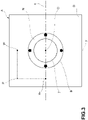
- a work vehicle 1 such as a compact wheel loader
- the invention is not limited to such a kind of work vehicle, but is applicable to any other kind of work vehicle.
- a compact wheel loader includes a bucket 2 connected to a frame 3 of the work vehicle for movement relative thereto. As shown, a pair of booms 5 (only one being shown) is each pivotally connected at one end on opposite sides of frame 3. The bucket 2 is pivotally connected at the opposite end of booms for tilting movement relative to the frame 3 about a generally horizontal axis.
- the above-described features form no substantial part of the present invention and are generally well known in the art.
- a bucket may be replaced in operation by any other implement or attachment.
- the movement of the boom 5 and of the bucket 2 is controlled by the user through a joystick 7 placed inside an operator's cab or cabin 9 of the work vehicle 1.
- a joystick 7 placed inside an operator's cab or cabin 9 of the work vehicle 1.
- FIG 2 which shows a control diagram of the work vehicle 1
- the boom 5 and the bucket 2 are moved by an hydraulic control circuit 10 comprising a first and a second hydraulic actuators 12, 14 which are controlled by an electronic control unit 16 through respective solenoid valves 18, 20 according to the position of the joystick 7 controlled by the user.
- Figure 3 shows an exemplary joystick of a work vehicle.
- a movement of the joystick in an associated bi-dimensional control area A according to a first direction y causes the actuation of the boom and a movement of the joystick in said control area A according to a second direction x causes the actuation of the implement.
- the intersection of said x and y directions is defined as origin O of the control area A, and corresponds to the neutral position of the joystick.
- a neutral region N around the neutral position of the joystick is a region where the boom and implement are not actuated.
- a region externally surrounding the neutral region is defined a driving region and indicated D in this figure.
- the implement when the joystick is moved up from the origin O of the control area A according to the y direction the boom is lowered with respect to ground and when the joystick is moved down from the origin O according to the y direction the boom is lifted towards ground.
- the implement e.g. a bucket
- the implement when the joystick is moved right from the origin O according to the x direction the implement, e.g. a bucket, is tilted towards a dumping position
- the implement e.g. the bucket, is tilted towards a dig position and beyond.
- a combination of movement in both directions x and y of the joystick is allowed in order to move simultaneously the boom and the bucket.
- Load-sensing valves allow a pressure compensation so that downstream channels take proportional allocation of flow depending on the load.
- the flow rate at a predetermined opening degree is not dependent upon the load downstream each valve and is not dependent upon the pump inlet flow.
- load-sensing valves with flow sharing also prevent the working fluid from taking the path of least resistance.
- this solution is very expensive.
- open centre directional solenoid valves are less expensive than load-sensing valves.
- the flow rate at a predetermined opening degree is dependent upon the pump inlet flow, the number of valves supplied by the pump and the load downstream each valve.
- each hydraulic actuator comprises an hydraulic cylinder operatively connected respectively to the boom and the implement, that uses hydraulic power of a working fluid to facilitate mechanical operation, the working fluid being controlled by means of open centre directional solenoid valves 18, 20.
- a hydraulic actuator can exert a large force.
- the rate of actuation of the boom and implement is controlled by the opening degree of the respective open centre directional solenoid valve 18, 20 by means of a driving current thereof as a function of the position of the joystick.
- the hydraulic flow rate of the working fluid required to operate the boom and the implement is produced by a hydraulic fixed displacement pump P connected to a fluid reservoir T and driven by an internal combustion engine or an electrical motor M (hereinafter simply referred to as motor) of the vehicle, e.g. by a mechanical linkage. Therefore, the rate of movement of the boom and the implement at a predetermined joystick position is dependent upon the motor rotational speed. For instance, when the motor is working at a high rotational speed, it is necessary a minimum movement of the joystick by the user to start the movement of the boom and/or the implement. On the contrary, when the motor is working at a low rotational speed, it is necessary a large movement of the joystick by the user to start the movement of the boom and/or the bucket.
- the situation is similar when the user try to stop the movement of the boom and/or the implement through the joystick. For instance, when the motor is working at a high rotational speed, it is necessary to move the joistick at a first distance from a neutral position of the joystick to stop the actuation of the boom and/or the implement. On the contrary, when the motor is working at a low rotational speed, it is necessary to move the joistick at a second distance from a neutral position of the joystick, higher than said first distance, to stop the actuation of the boom and/or the implement.
- the aim of the present invention is to provide a solution that avoids the drawbacks of the prior art.
- an aim of the present invention is to improve the controllability of a boom and/or implement in a work vehicle in situations in which the motor may be working at high or low rotational speed.
- this aim is achieved by a control method for actuating a movement of at least one of a boom and an implement connected to the boom in a work vehicle powered by a motor, having the features claimed in claim 1.
- control system for actuating a movement of at least one of a boom and an implement connected to the boom in a work vehicle powered by a motor, as well as a work vehicle, as claimed.
- an actuation strategy of a boom and/or an implement (and possibly of any further attachment) of a work vehicle is disclosed according to which the opening of at least one of the open centre directional solenoid valves of the hydraulic actuating means of the boom and the implement is modulated by considering the motor speed so as to guarantee that the start/stop movement of the boom or the implement occurs always at the same joystick position.
- actuation of the boom 5 and the implement 2 occurs by means of joystick 7 controlled by a user, whose movement in the control area A according to direction y causes the actuation of the boom 5 by first hydraulic actuating means 12 and whose movement in the control area A according to direction x causes the actuation of the implement 2 by second hydraulic actuating means 14.
- Each hydraulic actuating means 12, 14 include an hydraulic cylinder operatively connected respectively to the boom 5 and the implement 2, and a respective first and second open centre directional solenoid valve 18, 20 whose opening degree is adapted to control the flow of a working fluid to the respective hydraulic cylinder.
- An hydraulic flow rate of the working fluid is produced by a hydraulic pump P driven by the motor M.
- the rate of actuation of the boom 5 is controlled by the opening degree of the first open centre directional solenoid valve 18 by means of the driving current thereof as a function of a first component of the position P of the joystick 7 along direction y in the control area A.
- the rate of actuation of the implement 2 is controlled by the opening degree of the second open centre directional solenoid valve 20 by means of the driving current thereof as a function of a second component of the position P of the joystick 7 along direction x in the control area A.
- the first component of the position P of the joystick 7 along direction y is indicated y P in figure 3 and is the projection over y axis of a vector representing the position P of the joystick in the control area A.
- the second component of the position P of the joystick 7 along direction x is indicated x P in figure 3 and is the projection over x axis of the vector representing the position P of the joystick in the control area A.
- the driving region D and the neutral region N are separated by a preset boundary B.
- the control method comprises the step of providing a predetermined reference model of at least one among the driving current of the first open centre directional solenoid valve 18 and the driving current of the second open centre directional solenoid valve 20, indicative of the relation between the driving current and the rotational speed of the motor.
- control method comprises the step of acquiring a signal Se or data indicative of the current rotational speed of the motor M.
- an actual driving current value is retrieved from the reference model according to the acquired signal or data indicative of the current rotational speed of the motor M.
- the retrieved actual driving current value being intended to at least one among the first open centre directional solenoid valve 18 or the second open centre directional solenoid valve 20.
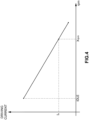
- FIG. 4 An exemplary reference model is illustrated in figure 4 .
- On the Y-axis are reported the driving current values and on the X-axis are reported the values of motor rotational speed in rpm, revolutions per minute.
- the driving current value I x is retrieved from the reference model. Then, the driving current value I x is used to actuates at least one among the first open centre directional solenoid valve or the second open centre directional solenoid valve.
- the reference model is an analytic model or a look-up table.
- the preset boundary can have a constant distance from the neutral position of the joystick, i.e. the intersection of the first preset direction x and the second preset direction y.
- the preset boundary B may have an ellipsoidal shape.
- the preset boundary B is pre-set by the manufacturer of the work vehicle 1.
- the reference model includes a plurality of driving current curves as a function of the distance of the preset boundary from the neutral position of the joystick, said plurality of driving current curves being not parallel.
- the neutral region N can be a region around a position of intersection O of said first and second preset directions x, y, and said driving region D can be a region surrounding said neutral region N.
- the invention concerns also a control system 10 for actuating a movement of at least one of a boom 5 and an implement 2 connected to the boom 5 in a work vehicle 1 powered by a motor.
- the control system 10 comprises input means adapted to receive at least a signal S J indicative of a position in a control area of a joystick 7 controlled by a user for actuating the boom 5 and the implement 2, and input means adapted to receive a signal S e indicative of the rotational speed of the motor M.
- control system 10 comprises storage means adapted to store a reference model of at least one among the driving current of the first open centre directional solenoid valve 18 and the driving current of the second open centre directional solenoid valve 20, indicative of the relation between at least the position of the preset boundary B and the rotational speed of the motor M.
- control system 10 comprises output means adapted to issue at least a signal S DC indicative of a driving current intended to control an opening degree of at least an open centre directional solenoid valve of hydraulic actuating means of said at least one of a boom 5 and an implement 2.
- the control system 10 is arranged to carry out a control method according to the invention.
- the invention concerns also a work vehicle 1, in particular compact wheel loader, comprising a motor M arranged to power the work vehicle 1, a boom 5 and an implement 2 connected to the boom 5, a joystick 7 operatively controlled by a user for actuating the boom 5 and the implement2.
- the joystick 7 is movable in a predetermined control area A according to a first preset direction x for actuating the boom 5 and in a second preset direction y for actuating the implement 2.
- first hydraulic actuating means 12 for actuating the boom 5 and second hydraulic actuating means 14 for actuating the implement 2.
- the first hydraulic actuating means and the second hydraulic actuating means each include an hydraulic cylinder operatively connected respectively to the boom 5 and the implement 2, and a respective first and second open centre directional solenoid valve 18, 20 whose opening degree is adapted to control the flow of a working fluid to the respective hydraulic cylinder.
- the opening degree of said first and second open centre directional solenoid valve 18,20 is operatively controlled by means of a respective driving current.
- the work vehicle includes a hydraulic pump P driven by the motor M to produce an hydraulic flow rate of the working fluid, and a control system for actuating the movement of at least one of the boom and the implement, according to the invention.
- the uncertainty about the position of the joystick in which the actuation of the boom and/or the implement is started and stopped is eliminated. Therefore, the controllability of the boom and/or implement and possible auxiliary attachments by the user and the working precision of work vehicle are increased.
Landscapes
- Engineering & Computer Science (AREA)
- Mining & Mineral Resources (AREA)
- Civil Engineering (AREA)
- General Engineering & Computer Science (AREA)
- Structural Engineering (AREA)
- Mechanical Engineering (AREA)
- Physics & Mathematics (AREA)
- Fluid Mechanics (AREA)
- Operation Control Of Excavators (AREA)
- Harvester Elements (AREA)
Claims (6)
- Procédé de commande d'actionnement d'un mouvement d'au moins un parmi une flèche (5) et un outil (2) relié à la flèche dans un véhicule de travail (1) alimenté par un moteur (M),dans lequel l'actionnement de la flèche (5) et de l'outil (2) se produit au moyen d'une manette (7) commandée par un utilisateur, un mouvement de la manette dans une zone de commande prédéterminée (A) selon une première direction prédéfinie (y) provoquant l'actionnement de la flèche (5) par des premiers moyens d'actionnement hydraulique (12) et un mouvement de la manette (7) dans ladite zone de commande (A) selon une seconde direction prédéfinie () provoquant l'actionnement de l'outil (2) par des seconds moyens d'actionnement hydraulique (14),dans lequel les premiers moyens d'actionnement hydraulique (12) et les seconds moyens d'actionnement hydraulique (14) comprennent chacun un cylindre hydraulique relié de manière fonctionnelle respectivement à la flèche (5) et à l'outil (2), et une première et une seconde électrovanne directionnelle à centre ouvert respective (18, 20) dont le degré d'ouverture est adapté pour commander l'écoulement d'un fluide de travail vers le cylindre hydraulique respectif ; une pression hydraulique du fluide de travail étant produite par une pompe hydraulique (P) alimentée par le moteur (M) ;la vitesse d'actionnement de la flèche (5) étant commandée par le degré d'ouverture de la première électrovanne directionnelle à centre ouvert (18) au moyen d'un courant d'attaque de celle-ci en fonction d'une première composante de la position de la manette (7) le long de ladite première direction prédéfinie (y) dans la zone de commande, et la vitesse d'actionnement de l'outil (2) étant commandée par le degré d'ouverture de la seconde électrovanne directionnelle à centre ouvert (20) au moyen d'un courant d'attaque de celle-ci en fonction d'une seconde composante de la position de la manette (7) le long de ladite seconde direction prédéfinie (x) dans la zone de commande (A) ;la zone de commande (A) de la manette (7) comprenant une zone d'entraînement (D) et une zone neutre (N) autour d'une position neutre de la manette, la zone d'entraînement et la zone neutre étant séparées par une limite prédéfinie ;le procédé de commande étant caractérisé en ce qu'il comprend en outre les étapes consistant à :a) fournir un modèle de référence prédéterminé d'au moins un parmi le courant d'attaque de la première électrovanne directionnelle à centre ouvert (18) et le courant d'attaque de la seconde électrovanne directionnelle à centre ouvert (20), indiquant la relation entre le courant d'attaque et la vitesse de rotation du moteur (M) ;b) acquérir un signal (Sj) ou des données indiquant une position de la manette (7) dans ladite zone de commande (A) au cours du temps ;c) acquérir un signal (Se) ou des données indiquant la vitesse de rotation actuelle du moteur ;d) lorsque la manette est déplacée sur la limite prédéfinie, récupérer à partir du modèle de référence une valeur de courant d'attaque réelle en fonction du signal ou des données acquises indiquant la vitesse de rotation actuelle du moteur (M), la valeur de courant d'attaque réelle récupérée étant destinée à au moins une parmi la première électrovanne directionnelle à centre ouvert ou la seconde électrovanne directionnelle à centre ouvert.
- Procédé de commande selon la revendication 1, dans lequel le modèle de référence est un modèle analytique ou une table de recherche.
- Procédé de commande selon la revendication 1 ou 2, dans lequel la limite prédéfinie présente une distance constante par rapport à la position neutre de la manette (7).
- Procédé de commande selon l'une quelconque des revendications précédentes, dans lequel ledit modèle de référence comprend une pluralité de courbes de courant d'attaque en fonction de la distance de la limite prédéfinie par rapport à la position neutre de la manette (7).
- Système de commande (10) d'actionnement d'un mouvement d'au moins un parmi une flèche (5) et un outil (2) relié à la flèche dans un véhicule de travail (1) alimenté par un moteur (M), comprenant :- des premiers moyens d'entrée adaptés pour recevoir au moins un signal (Sj) indiquant une position dans une zone de commande (A) d'une manette (7) commandée par un utilisateur pour actionner la flèche (5) et l'outil (2) ;- des seconds moyens d'entrée adaptés pour recevoir au moins un signal (Se) indiquant la vitesse de rotation du moteur (M) ;- des moyens de stockage adaptés pour stocker un modèle de référence d'au moins un parmi le courant d'attaque de la première électrovanne directionnelle à centre ouvert (18) et le courant d'attaque de la seconde électrovanne directionnelle à centre ouvert (20), indiquant la relation entre au moins la position de la limite prédéfinie et la vitesse de rotation du moteur (M) ;- des moyens de sortie adaptés pour émettre au moins un signal (Soc) indiquant un courant d'attaque destiné à commander un degré d'ouverture d'au moins une électrovanne directionnelle à centre ouvert (18, 20) de moyens d'actionnement hydraulique (12, 14) dudit au moins un élément parmi une flèche (5) et un outil (2),le système étant caractérisé par la mise en oeuvre d'un procédé de commande selon l'une quelconque des revendications 1 à 4.
- Véhicule de travail (1), en particulier un chargeur sur pneus compact, comprenant :- un moteur (M) agencé pour alimenter le véhicule de travail (1) ;- une flèche (5) et un outil (2) relié à la flèche ;- une manette (7) commandée de manière fonctionnelle par un utilisateur pour actionner la flèche (5) et l'outil (7), la manette (7) étant mobile dans une zone de commande prédéterminée (A) selon une première direction prédéfinie (y) pour actionner la flèche et dans une seconde direction prédéfinie (x) pour actionner l'outil,- des premiers moyens d'actionnement hydraulique (12) pour actionner la flèche (5) et des seconds moyens d'actionnement hydraulique (14) pour actionner l'outil (2), dans lequel les premiers moyens d'actionnement hydraulique et les seconds moyens d'actionnement hydraulique comprennent chacun un cylindre hydraulique relié de manière fonctionnelle respectivement à la flèche et à l'outil, et une première et une seconde électrovanne directionnelle à centre ouvert (18, 20) dont le degré d'ouverture est adapté pour commander l'écoulement d'un fluide de travail vers le cylindre hydraulique respectif, le degré d'ouverture desdites première et seconde électrovannes directionnelles à centre ouvert étant commandé de manière fonctionnelle au moyen d'un courant d'attaque respectif ;- une pompe hydraulique (P) entraînée par le moteur (M) pour produire un débit hydraulique du fluide de travail ; et- un système de commande d'actionnement du mouvement d'au moins un parmi la flèche (5) et l'outil (2), selon la revendication 5.
Applications Claiming Priority (1)
| Application Number | Priority Date | Filing Date | Title |
|---|---|---|---|
| IT102019000005238A IT201900005238A1 (it) | 2019-04-05 | 2019-04-05 | Procedimento di controllo per l'attuazione di un movimento di almeno uno tra un braccio ed un attrezzo collegato al braccio in una macchina operatrice azionata da un motore, sistema di controllo corrispondente e macchina operatrice comprendente tale sistema di controllo |
Publications (2)
| Publication Number | Publication Date |
|---|---|
| EP3719220A1 EP3719220A1 (fr) | 2020-10-07 |
| EP3719220B1 true EP3719220B1 (fr) | 2023-03-15 |
Family
ID=67108097
Family Applications (1)
| Application Number | Title | Priority Date | Filing Date |
|---|---|---|---|
| EP20168289.5A Active EP3719220B1 (fr) | 2019-04-05 | 2020-04-06 | Procédé de commande d'actionnement d'un mouvement d'au moins une flèche et un outil connecté à la flèche dans un véhicule de travail alimenté par un moteur, système de commande correspondant et véhicule de travail comprenant un tel système de commande |
Country Status (2)
| Country | Link |
|---|---|
| EP (1) | EP3719220B1 (fr) |
| IT (1) | IT201900005238A1 (fr) |
Family Cites Families (3)
| Publication number | Priority date | Publication date | Assignee | Title |
|---|---|---|---|---|
| JP3940242B2 (ja) * | 1999-07-29 | 2007-07-04 | 日立建機株式会社 | 建設機械の油圧回路制御装置 |
| JP6259371B2 (ja) * | 2014-07-31 | 2018-01-10 | 株式会社クボタ | 作業機 |
| JP6695620B2 (ja) * | 2015-01-06 | 2020-05-20 | 住友重機械工業株式会社 | 建設機械 |
-
2019
- 2019-04-05 IT IT102019000005238A patent/IT201900005238A1/it unknown
-
2020
- 2020-04-06 EP EP20168289.5A patent/EP3719220B1/fr active Active
Also Published As
| Publication number | Publication date |
|---|---|
| EP3719220A1 (fr) | 2020-10-07 |
| IT201900005238A1 (it) | 2020-10-05 |
Similar Documents
| Publication | Publication Date | Title |
|---|---|---|
| EP2148958B1 (fr) | Procédé de récupération d'énergie potentielle pendant une opération d'abaissement d'une charge | |
| US9458842B2 (en) | Closed loop drive circuit with external brake assist | |
| EP2413005B1 (fr) | Véhicule de chantier | |
| US20130297155A1 (en) | Method for controlling a movement of a vehicle component | |
| US10246855B2 (en) | Material handling machine with bucket shake control system and method | |
| EP2980317A1 (fr) | Multiples modèles de commande pour machines hydraulique à commandes à la main et au pied | |
| US20070209356A1 (en) | Method for providing priority to steering wheel on machines with steering wheel and joystick | |
| EP3719221B1 (fr) | Procédé de commande pour actionner un mouvement d'agitation d'un seau connecté à une flèche dans un véhicule de travail alimenté par un moteur, système de commande correspondant et véhicule de travail comprenant un tel système de commande | |
| EP3719217B1 (fr) | Procédé de commande d'actionnement d'un mouvement de retour en position d'excavation d'un outil, tel qu'un godet, dans un véhicule de travail, système de commande correspondant et véhicule de travail comprenant un tel système de commande | |
| EP2901025B1 (fr) | Valve prioritaire double | |
| GB2522050A (en) | A method of operating a material handling machine | |
| EP3719220B1 (fr) | Procédé de commande d'actionnement d'un mouvement d'au moins une flèche et un outil connecté à la flèche dans un véhicule de travail alimenté par un moteur, système de commande correspondant et véhicule de travail comprenant un tel système de commande | |
| EP3719219B1 (fr) | Procédé de commande pour actionner un mouvement combiné d'une flèche et d'un outil dans un véhicule de travail, système de commande correspondant et véhicule de travail comprenant un tel système de commande | |
| EP3719218B1 (fr) | Procédé de commande d'actionnement d'un mouvement d'inversion d'au moins une flèche et d'un outil dans un véhicule de travail, système de commande correspondant et véhicule de travail comprenant un tel système de commande | |
| US11965314B2 (en) | Control methods for actuating the movement of a boom or an attachment in a work vehicle, corresponding control systems and work vehicles comprising such control systems | |
| EP4026953A1 (fr) | Procédé de commande permettant de sélectionner automatiquement un mode de fonctionnement d'un véhicule de travail, système de commande correspondant et véhicule de travail comportant ce système de commande | |
| EP3719216B1 (fr) | Procédé de commande d'actionnement d'un mouvement d'au moins une flèche et d'un outil connecté à la flèche dans un véhicule de travail, système de commande correspondant et véhicule de travail comprenant un tel système de commande | |
| US20230358021A1 (en) | Control method for executing a floating function of a boom, corresponding control systems and work vehicles comprising such control systems | |
| JP4227936B2 (ja) | ホイール式建設機械 | |
| EP4067581A1 (fr) | Procédé de commande de l'actionnement d'au moins un organe hydraulique d'un véhicule de travail ou agricole | |
| WO2022122761A1 (fr) | Procédés de détection d'une défaillance d'un moyen de détection de vitesse d'un engin de chantier, système de commande correspondant et engin de chantier comprenant un tel système de commande | |
| JP2008121193A (ja) | ホイール式の建設機械 | |
| US20160298314A1 (en) | System and method for machine control | |
| CN115042635A (zh) | 自推进式作业车辆和对该车辆进行控制的计算机实现方法 |
Legal Events
| Date | Code | Title | Description |
|---|---|---|---|
| PUAI | Public reference made under article 153(3) epc to a published international application that has entered the european phase |
Free format text: ORIGINAL CODE: 0009012 |
|
| STAA | Information on the status of an ep patent application or granted ep patent |
Free format text: STATUS: THE APPLICATION HAS BEEN PUBLISHED |
|
| AK | Designated contracting states |
Kind code of ref document: A1 Designated state(s): AL AT BE BG CH CY CZ DE DK EE ES FI FR GB GR HR HU IE IS IT LI LT LU LV MC MK MT NL NO PL PT RO RS SE SI SK SM TR |
|
| AX | Request for extension of the european patent |
Extension state: BA ME |
|
| STAA | Information on the status of an ep patent application or granted ep patent |
Free format text: STATUS: REQUEST FOR EXAMINATION WAS MADE |
|
| 17P | Request for examination filed |
Effective date: 20210407 |
|
| RBV | Designated contracting states (corrected) |
Designated state(s): AL AT BE BG CH CY CZ DE DK EE ES FI FR GB GR HR HU IE IS IT LI LT LU LV MC MK MT NL NO PL PT RO RS SE SI SK SM TR |
|
| GRAP | Despatch of communication of intention to grant a patent |
Free format text: ORIGINAL CODE: EPIDOSNIGR1 |
|
| STAA | Information on the status of an ep patent application or granted ep patent |
Free format text: STATUS: GRANT OF PATENT IS INTENDED |
|
| INTG | Intention to grant announced |
Effective date: 20220901 |
|
| GRAJ | Information related to disapproval of communication of intention to grant by the applicant or resumption of examination proceedings by the epo deleted |
Free format text: ORIGINAL CODE: EPIDOSDIGR1 |
|
| STAA | Information on the status of an ep patent application or granted ep patent |
Free format text: STATUS: REQUEST FOR EXAMINATION WAS MADE |
|
| GRAP | Despatch of communication of intention to grant a patent |
Free format text: ORIGINAL CODE: EPIDOSNIGR1 |
|
| STAA | Information on the status of an ep patent application or granted ep patent |
Free format text: STATUS: GRANT OF PATENT IS INTENDED |
|
| INTC | Intention to grant announced (deleted) | ||
| INTG | Intention to grant announced |
Effective date: 20230104 |
|
| RIN1 | Information on inventor provided before grant (corrected) |
Inventor name: VENEZIA, ANTONIO Inventor name: LIBERTI, STEFANO Inventor name: GRAVILI, ANDREA Inventor name: GARRAMONE, ADRIANO |
|
| GRAS | Grant fee paid |
Free format text: ORIGINAL CODE: EPIDOSNIGR3 |
|
| GRAA | (expected) grant |
Free format text: ORIGINAL CODE: 0009210 |
|
| STAA | Information on the status of an ep patent application or granted ep patent |
Free format text: STATUS: THE PATENT HAS BEEN GRANTED |
|
| AK | Designated contracting states |
Kind code of ref document: B1 Designated state(s): AL AT BE BG CH CY CZ DE DK EE ES FI FR GB GR HR HU IE IS IT LI LT LU LV MC MK MT NL NO PL PT RO RS SE SI SK SM TR |
|
| REG | Reference to a national code |
Ref country code: CH Ref legal event code: EP Ref country code: GB Ref legal event code: FG4D |
|
| REG | Reference to a national code |
Ref country code: DE Ref legal event code: R096 Ref document number: 602020008798 Country of ref document: DE |
|
| REG | Reference to a national code |
Ref country code: IE Ref legal event code: FG4D |
|
| REG | Reference to a national code |
Ref country code: AT Ref legal event code: REF Ref document number: 1554074 Country of ref document: AT Kind code of ref document: T Effective date: 20230415 |
|
| RAP4 | Party data changed (patent owner data changed or rights of a patent transferred) |
Owner name: CNH INDUSTRIAL ITALIA S.P.A. |
|
| REG | Reference to a national code |
Ref country code: LT Ref legal event code: MG9D |
|
| REG | Reference to a national code |
Ref country code: NL Ref legal event code: MP Effective date: 20230315 |
|
| PG25 | Lapsed in a contracting state [announced via postgrant information from national office to epo] |
Ref country code: RS Free format text: LAPSE BECAUSE OF FAILURE TO SUBMIT A TRANSLATION OF THE DESCRIPTION OR TO PAY THE FEE WITHIN THE PRESCRIBED TIME-LIMIT Effective date: 20230315 Ref country code: NO Free format text: LAPSE BECAUSE OF FAILURE TO SUBMIT A TRANSLATION OF THE DESCRIPTION OR TO PAY THE FEE WITHIN THE PRESCRIBED TIME-LIMIT Effective date: 20230615 Ref country code: LV Free format text: LAPSE BECAUSE OF FAILURE TO SUBMIT A TRANSLATION OF THE DESCRIPTION OR TO PAY THE FEE WITHIN THE PRESCRIBED TIME-LIMIT Effective date: 20230315 Ref country code: LT Free format text: LAPSE BECAUSE OF FAILURE TO SUBMIT A TRANSLATION OF THE DESCRIPTION OR TO PAY THE FEE WITHIN THE PRESCRIBED TIME-LIMIT Effective date: 20230315 Ref country code: HR Free format text: LAPSE BECAUSE OF FAILURE TO SUBMIT A TRANSLATION OF THE DESCRIPTION OR TO PAY THE FEE WITHIN THE PRESCRIBED TIME-LIMIT Effective date: 20230315 |
|
| PGFP | Annual fee paid to national office [announced via postgrant information from national office to epo] |
Ref country code: IT Payment date: 20230501 Year of fee payment: 4 Ref country code: FR Payment date: 20230425 Year of fee payment: 4 Ref country code: DE Payment date: 20230426 Year of fee payment: 4 |
|
| REG | Reference to a national code |
Ref country code: AT Ref legal event code: MK05 Ref document number: 1554074 Country of ref document: AT Kind code of ref document: T Effective date: 20230315 |
|
| PG25 | Lapsed in a contracting state [announced via postgrant information from national office to epo] |
Ref country code: SE Free format text: LAPSE BECAUSE OF FAILURE TO SUBMIT A TRANSLATION OF THE DESCRIPTION OR TO PAY THE FEE WITHIN THE PRESCRIBED TIME-LIMIT Effective date: 20230315 Ref country code: NL Free format text: LAPSE BECAUSE OF FAILURE TO SUBMIT A TRANSLATION OF THE DESCRIPTION OR TO PAY THE FEE WITHIN THE PRESCRIBED TIME-LIMIT Effective date: 20230315 Ref country code: GR Free format text: LAPSE BECAUSE OF FAILURE TO SUBMIT A TRANSLATION OF THE DESCRIPTION OR TO PAY THE FEE WITHIN THE PRESCRIBED TIME-LIMIT Effective date: 20230616 Ref country code: FI Free format text: LAPSE BECAUSE OF FAILURE TO SUBMIT A TRANSLATION OF THE DESCRIPTION OR TO PAY THE FEE WITHIN THE PRESCRIBED TIME-LIMIT Effective date: 20230315 |
|
| PG25 | Lapsed in a contracting state [announced via postgrant information from national office to epo] |
Ref country code: SM Free format text: LAPSE BECAUSE OF FAILURE TO SUBMIT A TRANSLATION OF THE DESCRIPTION OR TO PAY THE FEE WITHIN THE PRESCRIBED TIME-LIMIT Effective date: 20230315 Ref country code: RO Free format text: LAPSE BECAUSE OF FAILURE TO SUBMIT A TRANSLATION OF THE DESCRIPTION OR TO PAY THE FEE WITHIN THE PRESCRIBED TIME-LIMIT Effective date: 20230315 Ref country code: PT Free format text: LAPSE BECAUSE OF FAILURE TO SUBMIT A TRANSLATION OF THE DESCRIPTION OR TO PAY THE FEE WITHIN THE PRESCRIBED TIME-LIMIT Effective date: 20230717 Ref country code: ES Free format text: LAPSE BECAUSE OF FAILURE TO SUBMIT A TRANSLATION OF THE DESCRIPTION OR TO PAY THE FEE WITHIN THE PRESCRIBED TIME-LIMIT Effective date: 20230315 Ref country code: EE Free format text: LAPSE BECAUSE OF FAILURE TO SUBMIT A TRANSLATION OF THE DESCRIPTION OR TO PAY THE FEE WITHIN THE PRESCRIBED TIME-LIMIT Effective date: 20230315 Ref country code: CZ Free format text: LAPSE BECAUSE OF FAILURE TO SUBMIT A TRANSLATION OF THE DESCRIPTION OR TO PAY THE FEE WITHIN THE PRESCRIBED TIME-LIMIT Effective date: 20230315 Ref country code: AT Free format text: LAPSE BECAUSE OF FAILURE TO SUBMIT A TRANSLATION OF THE DESCRIPTION OR TO PAY THE FEE WITHIN THE PRESCRIBED TIME-LIMIT Effective date: 20230315 |
|
| PG25 | Lapsed in a contracting state [announced via postgrant information from national office to epo] |
Ref country code: SK Free format text: LAPSE BECAUSE OF FAILURE TO SUBMIT A TRANSLATION OF THE DESCRIPTION OR TO PAY THE FEE WITHIN THE PRESCRIBED TIME-LIMIT Effective date: 20230315 Ref country code: PL Free format text: LAPSE BECAUSE OF FAILURE TO SUBMIT A TRANSLATION OF THE DESCRIPTION OR TO PAY THE FEE WITHIN THE PRESCRIBED TIME-LIMIT Effective date: 20230315 Ref country code: IS Free format text: LAPSE BECAUSE OF FAILURE TO SUBMIT A TRANSLATION OF THE DESCRIPTION OR TO PAY THE FEE WITHIN THE PRESCRIBED TIME-LIMIT Effective date: 20230715 |
|
| REG | Reference to a national code |
Ref country code: CH Ref legal event code: PL |
|
| REG | Reference to a national code |
Ref country code: DE Ref legal event code: R097 Ref document number: 602020008798 Country of ref document: DE |
|
| PG25 | Lapsed in a contracting state [announced via postgrant information from national office to epo] |
Ref country code: LU Free format text: LAPSE BECAUSE OF NON-PAYMENT OF DUE FEES Effective date: 20230406 |
|
| REG | Reference to a national code |
Ref country code: BE Ref legal event code: MM Effective date: 20230430 |
|
| PG25 | Lapsed in a contracting state [announced via postgrant information from national office to epo] |
Ref country code: MC Free format text: LAPSE BECAUSE OF FAILURE TO SUBMIT A TRANSLATION OF THE DESCRIPTION OR TO PAY THE FEE WITHIN THE PRESCRIBED TIME-LIMIT Effective date: 20230315 |
|
| PLBE | No opposition filed within time limit |
Free format text: ORIGINAL CODE: 0009261 |
|
| STAA | Information on the status of an ep patent application or granted ep patent |
Free format text: STATUS: NO OPPOSITION FILED WITHIN TIME LIMIT |
|
| PG25 | Lapsed in a contracting state [announced via postgrant information from national office to epo] |
Ref country code: SI Free format text: LAPSE BECAUSE OF FAILURE TO SUBMIT A TRANSLATION OF THE DESCRIPTION OR TO PAY THE FEE WITHIN THE PRESCRIBED TIME-LIMIT Effective date: 20230315 Ref country code: MC Free format text: LAPSE BECAUSE OF FAILURE TO SUBMIT A TRANSLATION OF THE DESCRIPTION OR TO PAY THE FEE WITHIN THE PRESCRIBED TIME-LIMIT Effective date: 20230315 Ref country code: LI Free format text: LAPSE BECAUSE OF NON-PAYMENT OF DUE FEES Effective date: 20230430 Ref country code: DK Free format text: LAPSE BECAUSE OF FAILURE TO SUBMIT A TRANSLATION OF THE DESCRIPTION OR TO PAY THE FEE WITHIN THE PRESCRIBED TIME-LIMIT Effective date: 20230315 Ref country code: CH Free format text: LAPSE BECAUSE OF NON-PAYMENT OF DUE FEES Effective date: 20230430 |
|
| REG | Reference to a national code |
Ref country code: IE Ref legal event code: MM4A |
|
| 26N | No opposition filed |
Effective date: 20231218 |
|
| PG25 | Lapsed in a contracting state [announced via postgrant information from national office to epo] |
Ref country code: BE Free format text: LAPSE BECAUSE OF NON-PAYMENT OF DUE FEES Effective date: 20230430 |
|
| PG25 | Lapsed in a contracting state [announced via postgrant information from national office to epo] |
Ref country code: IE Free format text: LAPSE BECAUSE OF NON-PAYMENT OF DUE FEES Effective date: 20230406 |
|
| PG25 | Lapsed in a contracting state [announced via postgrant information from national office to epo] |
Ref country code: IE Free format text: LAPSE BECAUSE OF NON-PAYMENT OF DUE FEES Effective date: 20230406 |