EP3718659A1 - Automationsgerät - Google Patents
Automationsgerät Download PDFInfo
- Publication number
- EP3718659A1 EP3718659A1 EP19000169.3A EP19000169A EP3718659A1 EP 3718659 A1 EP3718659 A1 EP 3718659A1 EP 19000169 A EP19000169 A EP 19000169A EP 3718659 A1 EP3718659 A1 EP 3718659A1
- Authority
- EP
- European Patent Office
- Prior art keywords
- axis
- movement
- horizontal slide
- drive
- automation device
- Prior art date
- Legal status (The legal status is an assumption and is not a legal conclusion. Google has not performed a legal analysis and makes no representation as to the accuracy of the status listed.)
- Granted
Links
- 230000033001 locomotion Effects 0.000 claims abstract description 87
- 239000002184 metal Substances 0.000 description 14
- 229910052751 metal Inorganic materials 0.000 description 14
- 238000004519 manufacturing process Methods 0.000 description 8
- 238000005516 engineering process Methods 0.000 description 5
- 238000000034 method Methods 0.000 description 4
- 238000003825 pressing Methods 0.000 description 4
- 238000006073 displacement reaction Methods 0.000 description 2
- 238000003754 machining Methods 0.000 description 2
- 230000005540 biological transmission Effects 0.000 description 1
- 238000000151 deposition Methods 0.000 description 1
- 230000007246 mechanism Effects 0.000 description 1
- 230000007935 neutral effect Effects 0.000 description 1
- 238000003860 storage Methods 0.000 description 1
- 239000013589 supplement Substances 0.000 description 1
Images


Classifications
-
- B—PERFORMING OPERATIONS; TRANSPORTING
- B21—MECHANICAL METAL-WORKING WITHOUT ESSENTIALLY REMOVING MATERIAL; PUNCHING METAL
- B21D—WORKING OR PROCESSING OF SHEET METAL OR METAL TUBES, RODS OR PROFILES WITHOUT ESSENTIALLY REMOVING MATERIAL; PUNCHING METAL
- B21D43/00—Feeding, positioning or storing devices combined with, or arranged in, or specially adapted for use in connection with, apparatus for working or processing sheet metal, metal tubes or metal profiles; Associations therewith of cutting devices
- B21D43/02—Advancing work in relation to the stroke of the die or tool
- B21D43/04—Advancing work in relation to the stroke of the die or tool by means in mechanical engagement with the work
- B21D43/05—Advancing work in relation to the stroke of the die or tool by means in mechanical engagement with the work specially adapted for multi-stage presses
- B21D43/052—Devices having a cross bar
-
- B—PERFORMING OPERATIONS; TRANSPORTING
- B21—MECHANICAL METAL-WORKING WITHOUT ESSENTIALLY REMOVING MATERIAL; PUNCHING METAL
- B21D—WORKING OR PROCESSING OF SHEET METAL OR METAL TUBES, RODS OR PROFILES WITHOUT ESSENTIALLY REMOVING MATERIAL; PUNCHING METAL
- B21D43/00—Feeding, positioning or storing devices combined with, or arranged in, or specially adapted for use in connection with, apparatus for working or processing sheet metal, metal tubes or metal profiles; Associations therewith of cutting devices
- B21D43/02—Advancing work in relation to the stroke of the die or tool
- B21D43/04—Advancing work in relation to the stroke of the die or tool by means in mechanical engagement with the work
- B21D43/10—Advancing work in relation to the stroke of the die or tool by means in mechanical engagement with the work by grippers
- B21D43/105—Manipulators, i.e. mechanical arms carrying a gripper element having several degrees of freedom
Definitions
- the present invention relates to an automation device with a base body with a plurality of carriages which can be moved relative to one another via a plurality of axes of movement and orientation axes in order to automatically displace at least one workpiece from a first location to a second location that is different from the first location
- a plurality of slides comprises an X1 horizontal slide and an X2 horizontal slide, which are telescopically movable along the X movement axis.
- Such an automation device is used, for example, in forming technology.
- sheet metal parts go through so-called pressing lines with different processing sections in which the sheet metal parts are formed by forming tools. Between the processing sections, the sheet metal parts accumulating at the end of a respective processing section must be unloaded, reloaded and / or loaded.
- the displacement of the sheet metal parts at the end of a processing section and / or at the beginning of a processing section or between a first processing section and a second processing section require a high degree of precision and are therefore carried out using automation.
- the automation can be implemented in the form of standard robots, which are supplemented by appropriate grippers or even additional axes, or from automation devices specially designed for press automation.
- automated device should also include the term “standard robot with supplement”.
- an automation device mentioned at the beginning is off WO 00/2011067260 A1 and from WO 00/2015000855 A1 known.
- automation devices are used that comprise six axes.
- automation devices in linear technology which have an advantage over standard robots in terms of speed and range, these six axes are not easy to implement for reasons of space.
- the object of the present invention is therefore to develop an automation device of the type mentioned at the beginning in such a way that it requires less space than automation devices of the prior art.
- the object is achieved according to the invention in that the X1 horizontal slide and the X2 horizontal slide can be pivoted about the A orientation axis.
- the pivotability of the XI horizontal slide and the X2 horizontal slide around the A orientation axis allows the two horizontal slides to move in an additional direction that can be controlled directly. This increases the degree of freedom of the automation device and creates an additional possibility of storing workpieces in a position that was previously only accessible via detours.
- Another advantage of the present invention is that the X1 and X2 horizontal slides are connected to a drive device for movement around the A orientation axis, around the B orientation axis and along the Y movement axis. It is advantageous to combine a drive device for moving both horizontal slides about three axes. This reduces the space required for the drive device.
- the drive device comprises an A drive for rotation about the A orientation axis, a B drive for rotation about the B orientation axis and a Y drive for movement along the B movement axis and in the Base body is arranged below the Z movement axis.
- the combination of the respective drives for the respective axes and their arrangement below the Z movement axis has the advantage that they are spatially remote from the respective slide and can therefore be arranged at a location that does not restrict the space requirement in the workroom.
- Another advantage of the present invention is that the X1 horizontal slide is movably supported on the base body and the X2 horizontal slide is movably supported on the X1 horizontal slide. This enables a telescopic linear displacement of the horizontal slide in relation to the base body.
- the X2 horizontal slide has at least one support beam with the Y axis of movement and the plurality of slides comprises at least one Y horizontal slide which is movable along the Y movement axis of the support beam. This also optimizes the freedom of movement of the automation device in the workroom.
- the X2 horizontal slide has a first support beam and a second support beam each with one of the Y movement axes, on each of which a first and second Y horizontal slide can be moved along the Y movement axis.
- the freedom of movement of the automation device according to the invention is thereby further optimized.
- the Y drive drives the first Y horizontal slide independently of the second Y horizontal slide. It is particularly advantageous that the B drive also drives the first Y horizontal slide independently of the second Y horizontal slide. This means that the spaces available on both sides of the X1 horizontal slide can be used independently can be used optimally for the relocation of workpieces.
- the drive device with the respective drives is arranged outside of the work space and thus does not restrict the space required for moving workpieces.
- a production plant 1 is shown schematically by way of example in the form of a press line with three processing sections 3, 5, 7.
- the processing sections 3, 5, 7 are arranged in a row one behind the other.
- the processing sections 3, 5, 7 can also be arranged not (only) in a straight row one behind the other but also offset and / or at an angle to one another.
- the arrangement of the individual processing sections 3, 5, 7 generally depends on the space available and the space required by the production plant.
- the spatial arrangement of the individual processing sections 3, 5, 7 with respect to one another is therefore not relevant to the invention and can therefore be planned as required as required.
- the present invention also includes systems with only a single processing section 3, 5, 7.
- Each machining section 3, 5, 7 forms a tool space 9 in which a tool 10 machines a workpiece 12 in a predetermined manner.
- the predetermined The way of processing is carried out by a control of the respective processing section 3, 5, 7 or the production plant 1.
- Such a control takes place via suitable software and hardware, which is generally known and is not the subject of the present invention. This is therefore not discussed further here.
- the processing sections 3, 5, 7 are presses in which sheet metal parts are pressed into a predetermined shape by a predetermined pressing process. In other embodiments, completely different machining operations, e.g. Assembly steps are carried out in the production plant 1 with the present invention.
- each processing section 3, 5, 7 forms a tool space 9 in which a workpiece 12 as a sheet metal part is placed on a lower tool 11 before a pressing process, in order then to carry out the predetermined pressing process with an upper tool 13.
- a sheet metal part must be loaded into the first processing section 3, unloaded from this first processing section 3 after processing in the first processing section 3 and transferred and loaded into the second processing section 3 in order to be processed there again and after processing by the second processing section 3 to be transferred to the third processing section 5 and loaded into it in order to be processed there again and finally to be unloaded from the third processing section 5.
- the loading, the transferring and the unloading are carried out before and between the respective processing sections 3, 5 and 7 by automation devices 100.
- a processing section 3 is shown schematically on a somewhat larger scale.
- the tool space 9 is defined in the context of the present invention as the space which is located between the lower tool 11 and the upper tool 13.
- the tool space 9 changes its height as a function of the distance between the upper tool 13 and the lower tool 11 and thus has its greatest volume when the upper tool 13 has moved at most from the lower tool, i.e. in a state that is suitable for loading and unloading a workpiece 12 is.
- two sheet metal parts B1, B2 are arranged next to one another on the lower tool 11. It can be clearly seen that the space requirement in the tool room 9 is a critical variable.
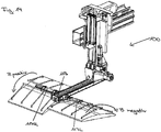
- FIG. 13 is a schematic perspective view of an automation device 100 according to the present invention, as shown in FIG Fig. 1 and Fig. 2 is used in the production plant 1 designed as a press line.
- a 3D coordinate system for representing the axes of movement and orientation axes of the automation device 100 is also shown.
- the automation device 100 has an X0 movement axis X0, an X1 movement axis X1, an X2 movement axis X2, which are assigned to an A-orientation axis A, a Y-movement axis Y to which a B-orientation axis B is assigned, and a Z. -Motion axis Z to which a C orientation axis C is assigned.
- the respective axes of movement and orientation are described in more detail below.
- the automation device 100 is designed symmetrically to the X1 movement axis X1.
- the automation device 100 has a base body 101 which essentially forms a Z-axis body 103 and comprises the Z-axis of movement Z.
- a Z vertical slide 105 is linearly displaceable along the Z movement axis Z.
- the base body 101 is connected to an X0 axis body 107 in a vertically overhead area and is attached to the X0 axis body 107 so as to be linearly displaceable via an X0 horizontal slide 109.
- the base body 101 can thus change its position horizontally along the X0 movement axis X0 and can change its position along the Z axis of movement Z vertically.
- the base body 101 is also connected via an X1 horizontal slide 111 to an X1 axis body 113, which can move linearly horizontally in relation to the base body 101.
- the X1 axle body 113 is in a position that has been advanced completely in the X direction.
- the X1 axis body 113 is formed symmetrically on both sides of the X1 movement axis X1.
- the two sides are identified as “left” and “right” from the perspective of the base body 101.
- the same components are denoted by the same reference symbols on both sides of the axis of symmetry.
- "L” for "left” and “R” for “right” are added to the respective reference numerals.
- a Y support beam 117L, 117R is attached to the X1 axis body 113 on both sides, that is to say left and right, via an X2 horizontal slide 112, and each includes a Y axis of movement Y.
- a gripping device 119L, 119R for gripping the workpiece 12 to be transported is located on the two Y support beams 117L, 117R Fig. 3 The gripping device 119L, 119R is just gripping such a workpiece 12.
- FIG. 14 is a schematic side view of the automation device 100 from FIG Fig. 3 shown.
- the Z vertical slide 105 can move along the Z movement axis Z and thus reduce or increase the distance between the X0 movement axis X0 and the X1 movement axis X1.
- Fig. 4 is the Z-vertical slide 105 moved upwards so that the distance between the X0 movement axis X0 and the X1 movement axis X1 is small.
- the Z-vertical slide has moved downwards so that the distance between the X0 movement axis X0 and the X1 movement axis X1 is large.
- FIG. 11 is a schematic side view of the automation device from FIG Fig. 3 in which an X0 horizontal slide 109 lies on the base body 101 at a first exemplary position, an X1 horizontal slide 111 lies at a first exemplary position in relation to the base body 101 and an X2 horizontal slide 112 lies in a first exemplary position in relation to the X1 -Horizontal slide 111 is located.
- FIG. 14 is a schematic side view of the automation device 100 from FIG Fig. 3 in a second exemplary position of the X0, X1 and X2 horizontal slides 109, 111, 112 in relation to the base body 101 and in comparison to the first position in FIG Fig. 6 shown.
- Fig. 6 and Fig. 7 should each give an example for the linear movement along the X0 movement axis, the X1 movement axis and the X2 movement axis. Any horizontally aligned position in the tool space 9 can thus be reached by the workpiece 12.
- Fig. 8 is schematically shown a perspective view obliquely from above of the left and right Y-horizontal slides 115L, 115R in a respective exemplary first position.
- the two Y horizontal slides 115L, 115R move on the left Y support beam 117L and the right Y support beam 117R, respectively and thus the gripping device 119L, 119R away from or towards the X1 axis body 113 with the X1 movement axis X1.
- a neutral position of the two Y-horizontal slides 115L, 115R is shown.
- Fig. 9 is a schematic perspective side view obliquely from above of the two Y-horizontal slides 115L, 115R in a second exemplary position, that is, in a position shifted to the right in the direction of the arrow.
- FIG. 10 A schematic, perspective side view of the automation device 100 according to the present invention is shown in a first exemplary position in relation to the A orientation axis A.
- a negative rotary movement of the X1 axle body 113 in direction A is indicated by an arrow.
- FIG. 3 is a schematic, perspective side view of the automation device 100 from FIG Fig. 10 in a second position in relation to the A orientation axis A.
- a movement in direction A positive is indicated by an arrow.
- Fig. 10 thus shows an example of a rotational movement of the X1 axle body 113 to the left, while Fig. 10 shows an example of a rotary movement of the X1 axle body 113 to the right.
- FIG. 3 is a schematic, perspective side view of the automation device from FIG Fig. 10 in a first position in relation to a B orientation axis B.
- a rotational movement of the Y support beam 117L, 117R in the positive direction B is indicated by an arrow.
- the direction B positive is therefore tilted towards the viewer.
- FIG. 3 is a schematic, perspective view of the automation device 100 from FIG Fig. 10 in a second position in relation to the B orientation axis B.
- a rotational movement of the Y support beam 117L, 117R in the negative direction B is also indicated here by an arrow.
- the second position in direction B negative is tilted backwards away from the viewer.
- FIG. 3 is a schematic, perspective view of the automation device 100 from FIG Fig. 10 , wherein the position of the Y support beam 117L and the position of the Y support beam 117R with respect to the B orientation axis B are different and opposite, respectively.
- the control of the automation device 100 allows independent control of the left Y-support beam 117L and the right Y-support beam 117R, for example in opposite directions around the (respective) B-orientation axis B.
- the positions are in FIG Fig. 14 so left B negative and right B positive.
- Fig. 15 13 is a schematic detailed view of a drive device 200 for a movement along the Y movement axis Y as well as a movement about the B orientation axis B and a movement about the A orientation axis A.
- the drive device 200 is in the area of the base body 101, essentially below the Z. Axis of movement Z.
- the drive device 200 comprises a left drive 200L and a right drive 200R, which can comprise one or more drive motors.
- the drive mechanisms on the left-hand side and on the right-hand side are identical, so that in the following the drive system is essentially based on the left-hand drive side is described. The description also applies to the right drive side. Reference is made to the right-hand drive side only in individual cases, when it is necessary for clarity.
- Fig. 15 shows the left drive side of the drive device 200.
- the drive device 200 comprises on the left drive side a bearing 201 for rotating the X1 axis body 113 about the A orientation axis A, a B drive 203L for rotating the Y support beam 117L about the B orientation axis B and a Y drive 205L for moving the Y horizontal slide 115L along the B movement axis B.
- the A drive 202 is indicated, which pivots the drive unit 200 around the bearing 201 with the aid of a spindle.
- the B drive 203L is arranged above the Y drive 205L in a space below the Z movement axis Z of the base body 101.
- the B drive 203L and the Y drive 205L are aligned transversely to the X1 movement axis X1 and each have a B or Y drive shaft 209L, 211L facing the observer.
- the B drive shaft 209L of the B drive 203L spatially protrudes somewhat further towards the viewer than the drive shaft 211L of the Y drive 205L located below it.
- a B or Y belt pulley 213L, 215L is arranged at the respective protruding, free ends of the drive shaft 209L or 211L.
- the above drive device 200 produces a rotational movement of the B and Y pulleys 213L, 215L.
- a Y drive belt 217L runs around the lower pulley 215L and over two Y deflection pulleys 218L along the left side of the X1 axle body 113, parallel to the X1 movement axis X1.
- a B drive belt 219L runs over B deflection rollers 221L parallel to the Y drive belt 217L and thus to the X1 movement axis X1.
- Fig. 16 the course of the Y drive belt 217L and the B drive belt 219L parallel to the X1 movement axis X1 at one end of the X1 axis body 113 is shown in detail.
- a large B pulley 223L around which the B drive belt 219L is passed
- a large Y pulley 225L around which the Y drive belt 217L is passed.
- a large Y and B belt pulley (not shown) so that the drive belts each form an upper run and a lower run.
- the lower run of the two B and Y drive belts 219L, 217L is guided around a B drive wheel 227L or a Y drive wheel 229L and then runs at the opposite rear end of the X1 axle body 113 around the respective large pulley there (not shown ) back to the pulley 215L or 213L drive device.
- the system is in Fig. 16 described for the left side, but also applies to the right drive side.
- the rotational movement of the Y support beam 117L about the B orientation axis B is indicated with an arrow.
- the Y-horizontal slide 115L with the gripping device 119L moves depending on the control of the Y-drive 205L along the Y-support beam 117L.
- Fig. 17 Fig. 13 is a schematic front view of the left Y-support beam 117L with the left Y-horizontal slide 115L.
- the Y drive wheel 229L drives a Y spindle 231L for movement along the Y movement axis Y, to which the Y horizontal slide 115L is attached via a spindle nut 233L.
- the gripping device 119L with a workpiece 12 can also be seen on the Y-horizontal slide 115L.
- the B drive wheel 227L for a movement about the B orientation axis B is part of a transmission 235L with a hollow shaft, which converts the rotary movement of the B drive wheel 227L into an in Fig. 16 implemented by the rotary movement of the Y-beam 117L shown by the arrow.
- This technology is also identical on the right-hand drive side.
Abstract
Description
- Die vorliegende Erfindung betrifft ein Automationsgerät mit einem Grundkörper mit einer Mehrzahl von Schlitten, die über eine Mehrzahl von Bewegungsachsen und Orientierungsachsen relativ zueinander bewegbar sind, um wenigstens ein Werkstück automatisch von einem ersten Ort zu einem vom ersten Ort unterschiedlichen zweiten Ort zu verlagern, wobei die Mehrzahl von Schlitten einen X1-Horizontalschlitten und einen X2-Horizontalschlitten umfasst, die entlang der X-Bewegungsachse teleskopisch bewegbar sind.
- Ein solches Automationsgerät wird zum Beispiel in der Umformtechnik eingesetzt. In der Umformtechnik durchlaufen Blechteile sogenannte Pressstraßen mit unterschiedlichen Bearbeitungsabschnitten, in denen die Blechteile durch Umformwerkzeuge umgeformt werden. Zwischen den Bearbeitungsabschnitten müssen die am Ende eines jeweiligen Bearbeitungsabschnitts auflaufenden Blechteile entladen, umgeladen und/oder beladen werden. Die Verlagerung der Blechteile am Ende eines Bearbeitungsabschnitts und/oder am Anfang eines Bearbeitungsabschnitts bzw. zwischen einem ersten Bearbeitungsabschnitt und einem zweiten Bearbeitungsabschnitt verlangen eine hohe Präzision und werden daher unter Einsatz von Automation durchgeführt.
- Die Automation kann in Form von Standardrobotern, die um entsprechende Greifer oder sogar Zusatzachsen ergänzt werden, oder aus speziell für die Pressenautomation vorgesehenen Automationsgeräten umgesetzt werden.
- Im Kontext der vorliegenden Erfindung soll der Begriff "Automationsgerät" auch den Begriff "Standardroboter mit Ergänzung" umfassen.
- So ist ein eingangs genanntes Automationsgerät zum Beispiel aus
WO 00/2011067260 A1 WO 00/2015000855 A1 - Beim Einsatz zum Beispiel in einer Pressenstraße ist von Bedeutung, dass zwischen Bearbeitungsabschnitten nur wenig Platz vorhanden ist und komplexe Bewegungsabläufe zur Verlagerung und/oder Umlagerung von Blechteilen in häufig beengten Werkräumen zuverlässig durchgeführt werden müssen.
- Bei dem Be- und Entladen der Blechteile und auch während des Weitertransports von einem Bearbeitungsabschnitt zu dem nächsten Bearbeitungsabschnitt werden Automationsgeräte eingesetzt, die sechs Achsen umfassen. Bei Automationsgeräten in Lineartechnik, welche einen Vorteil gegenüber Standardrobotern in Geschwindigkeit und Reichweite aufweisen, sind diese sechs Achsen aus Platzgründen nicht einfach zu realisieren.
- Die Aufgabe der vorliegenden Erfindung ist daher, ein Automationsgerät der eingangs genannten Art derart weiterzubilden, dass dieses weniger Platz benötigt als Automationsgeräte des Standes der Technik.
- Die Aufgabe wird erfindungsgemäß dadurch gelöst, dass der X1-Horizontalschlitten und der X2-Horizontalschlitten um die A-Orientierungsachse schwenkbar sind. Die Schwenkbarkeit des XI-Horizontalschlittens und des X2-Horizontalschlittens um die A-Orientierungsachse erlaubt eine zusätzliche Bewegungsrichtung der beiden Horizontalschlitten, die unmittelbar gesteuert werden kann. Dadurch wird der Freiheitsgrad des Automationsgerätes erhöht und eine zusätzliche Möglichkeit geschaffen, Werkstücke in einer bisher nur über Umwegen erreichbaren Position zu lagern.
- Ein weiterer Vorteil der vorliegenden Erfindung ist, dass der X1- und X2-Horizontalschlitten zur Bewegung um die A-Orientierungsachse, um die B-Orientierungsachse und entlang der Y-Bewegungsachse mit einer Antriebseinrichtung verbunden sind. Es ist günstig, eine Antriebseinrichtung für die Bewegung beider Horizontalschlitten um drei Achsen zusammenzufassen. Dadurch wird der Platzbedarf für die Antriebseinrichtung verringert.
- Ein weiterer Vorteil der vorliegenden Erfindung ist, dass die Antriebseinrichtung einen A-Antrieb zur Drehung um die A-Orientierungsachse, einen B-Antrieb zur Drehung um die B-Orientierungsachse und einen Y-Antrieb zur Bewegung entlang der B-Bewegungsachse umfasst und in dem Grundkörper unterhalb der Z-Bewegungsachse angeordnet ist. Die Zusammenfassung der jeweiligen Antriebe für die jeweiligen Achsen und deren Anordnung unterhalb der Z-Bewegungsachse hat den Vorteil, dass diese räumlich entfernt von dem jeweiligen Schlitten liegen und somit an einem Ort angeordnet werden können, der den Platzbedarf im Werkraum nicht einschränkt.
- Ein weiterer Vorteil der vorliegenden Erfindung ist, dass der X1-Horizontalschlitten an dem Grundkörper beweglich gelagert ist und der X2-Horizontalschlitten an dem X1-Horizontalschlitten beweglich gelagert ist. Dadurch wird eine teleskopartige Linearverschiebung der Horizontalschlitten in Bezug zum Grundkörper möglich.
- Ein weiterer Vorteil der vorliegenden Erfindung ist, dass der X2-Horizontalschlitten wenigstens einen Tragbalken mit der Y-Bewegungsachse aufweist und die Mehrzahl von Schlitten wenigstens einen Y-Horizontalschlitten umfasst, der entlang der Y-Bewegungsachse des Tragbalkens bewegbar ist. Auch dadurch wird die Bewegungsfreiheit des Automationsgerätes im Werkraum optimiert.
- Ein weiterer Vorteil der vorliegenden Erfindung ist, dass der X2-Horizontalschlitten einen ersten Tragbalken und einen zweiten Tragbalken mit jeweils einer der Y-Bewegungsachsen aufweist, an denen jeweils ein erster bzw. zweiter Y-Horizontalschlitten entlang der Y-Bewegungsachse bewegbar ist. Die Bewegungsfreiheit des erfindungsgemäßen Automationsgerätes wird dadurch weiter optimiert.
- Ein weiterer Vorteil der vorliegenden Erfindung ist, dass der Y-Antrieb den ersten Y-Horizontalschlitten unabhängig von dem zweiten Y-Horizontalschlitten antreibt. Besonders vorteilhaft ist, dass auch der B-Antrieb den ersten Y-Horizontalschlitten unabhängig von dem zweiten Y-Horizontalschlitten antreibt. Dadurch können die zur Verfügung stehenden Räume an beiden Seiten des X1-Horizontalschlittens unabhängig voneinander für die Verlagerung von Werkstücken optimal genutzt werden.
- In Bezug auf die Anordnung eines Automationsgerätes mit den Merkmalen eines der Ansprüche ist von Vorteil, dass die Antriebseinrichtung mit den jeweiligen Antrieben außerhalb des Werkraums angeordnet ist und somit den Platzbedarf für das Verlagern von Werkstücken nicht einschränkt.
- Eine Ausführungsform der vorliegenden Erfindung wird im Folgenden anhand der Zeichnung näher beschrieben. Es zeigen:
- Fig. 1
- eine schematische Ansicht einer Produktionsanlage, in der vier Automationsgeräte gemäß vorliegender Erfindung angeordnet sind;
- Fig. 2
- eine schematische, perspektivische Ansicht eines Bearbeitungsabschnitts der Produktionsanlage aus
Fig. 1 ; - Fig. 3
- eine schematische, perspektivische Ansicht eines Automationsgerätes gemäß vorliegender Erfindung, wie es in
Fig. 1 undFig. 2 eingesetzt ist und mit einer schematischen Erläuterung der Bewegungsachsen X, Y, Z und Orientierungsachsen A, B, C; - Fig. 4
- eine schematische Seitenansicht des Automationsgerätes aus
Fig. 3 in einer beispielhaften ersten Position eines Z-Vertikalschlittens; - Fig. 5
- eine schematische Seitenansicht des Automationsgerätes aus
Fig. 3 in einer beispielhaften zweiten Position des Z-Vertikalschlittens; - Fig. 6
- eine schematische Seitenansicht des Automationsgerätes aus
Fig. 3 in einer ersten beispielhaften Position eines XO-Horizontalschlittens, XI-Horizontalschlittens und eines X2-Horizontalschlittens; - Fig. 7
- eine schematische Seitenansicht des Automationsgerätes aus
Fig. 3 in einer zweiten beispielhaften Position der X0-, X1- und X2-Horizontalschlitten ausFig. 6 ; - Fig. 8
- eine schematische perspektivische Ansicht von schräg oben eines ersten und zweiten Y-Horizontalschlittens in einer beispielhaften ersten Position;
- Fig. 9
- eine schematische perspektivische Seitenansicht von schräg oben der beiden Y-Horizontalschlitten in einer zweiten beispielhaften Position;
- Fig. 10
- eine schematische perspektivische Seitenansicht des Automationsgerätes gemäß vorliegender Erfindung in einer ersten beispielhaften Position in Bezug zur A-Orientierungsachse;
- Fig. 11
- eine schematische, perspektivische Seitenansicht des Automationsgerätes aus
Fig. 10 in einer zweiten Position in Bezug zur A-Orientierungsachse; - Fig. 12
- eine schematische, perspektivische Seitenansicht des Automationsgerätes aus
Fig. 10 in einer ersten Position in Bezug zu einer B-Orientierungsachse; - Fig. 13
- eine schematische, perspektivische Ansicht des Automationsgerätes aus
Fig. 10 in einer zweiten Position in Bezug zu der B-Orientierungsachse; - Fig. 14
- schematische Detailansicht einer Antriebseinrichtung für Y-Bewegungsachse und B-Orientierungsachse;
- Fig. 15
- schematische Detailansicht des Bereichs X1-Bewegungsachse und Y-Bewegungsachse;
- Fig. 16
- schematische Vorderansicht eines Tragbalkens mit Y-Horizontalschlitten; und
- Fig. 17
- schematische Schnittdarstellung der Antriebstechnik für Y-Schlitten und B-Achse.
- In
Fig. 1 ist schematisch eine Produktionsanlage 1 beispielhaft in Form einer Pressenstraße mit drei Bearbeitungsabschnitten 3, 5, 7 dargestellt. In der dargestellten Ausführungsform sind die Bearbeitungsabschnitte 3, 5, 7 in einer Reihe hintereinander angeordnet. In anderen Ausführungsformen können die Bearbeitungsabschnitte 3, 5, 7 auch nicht (nur) in einer geraden Reihe hintereinander sondern auch versetzt und/oder in einem Winkel zueinander angeordnet sein. Die Anordnung der einzelnen Bearbeitungsabschnitte 3, 5, 7 hängt in der Regel von den zur Verfügung stehenden Räumlichkeiten und dem erforderlichen Platzbedarf der Produktionsanlage ab. Die räumliche Anordnung der einzelnen Bearbeitungsabschnitte 3, 5, 7 zueinander ist also nicht erfindungsrelevant und kann somit nach Bedarf beliebig geplant werden. Von der vorliegenden Erfindung umfasst sind auch Anlagen mit nur einem einzigen Bearbeitungsabschnitt 3, 5, 7. - Jeder Bearbeitungsabschnitt 3, 5, 7 bildet einen Werkzeugraum 9, in welchem ein Werkzeug 10 ein Werkstück 12 in vorbestimmter Weise bearbeitet. Die vorbestimmte Weise der Bearbeitung erfolgt durch eine Steuerung des jeweiligen Bearbeitungsabschnitts 3, 5, 7 bzw. der Produktionsanlage 1. Eine solche Steuerung erfolgt über geeignete Software und Hardware, die allgemein bekannt ist und nicht Gegenstand der vorliegenden Erfindung ist. Auf diese wird daher hier nicht weiter eingegangen.
- In der dargestellten Ausführungsform sind die Bearbeitungsabschnitte 3, 5, 7 Pressen, in denen Blechteile durch einen vorbestimmten Pressvorgang in eine vorbestimmte Form gepresst werden. In anderen Ausführungsformen können auch ganz andere Bearbeitungsvorgänge, z.B. Montageschritte, in der Produktionsanlage 1 mit der vorliegenden Erfindung durchgeführt werden.
- Für die hier beispielhaft beschriebene Anwendung als Pressenstraße bildet jeder Bearbeitungsabschnitt 3, 5, 7 einen Werkzeugraum 9, in welchem ein Werkstück 12 als Blechteil vor einem Pressvorgang auf einem Unterwerkzeug 11 abgelegt wird, um dann mit einem Oberwerkzeug 13 den vorbestimmten Pressvorgang durchzuführen. In der Pressenstraße wie in
Fig. 1 muss ein Blechteil in den ersten Bearbeitungsabschnitt 3 geladen werden, nach der Bearbeitung im ersten Bearbeitungsabschnitt 3 von diesem ersten Bearbeitungsabschnitt 3 entladen werden und in den zweiten Bearbeitungsabschnitt 3 überführt und geladen werden, um dort wieder bearbeitet zu werden und nach der Bearbeitung vom zweiten Bearbeitungsabschnitt 3 zum dritten Bearbeitungsabschnitt 5 überführt und in diesen geladen zu werden, um auch dort wieder bearbeitet zu werden und schließlich vom dritten Bearbeitungsabschnitt 5 entladen zu werden. - Die Vorgänge des anfänglichen Beladens am ersten Bearbeitungsabschnitts 3, der Überführung der in den jeweiligen Bearbeitungsabschnitten 3, 5 bearbeiteten Blechteile zum nachfolgenden Bearbeitungsabschnitt 5, 7 und das Entladen der in dieser Pressenstraße fertig bearbeiteten Blechteile aus dem dritten Bearbeitungsabschnitt 7 verlangt eine hohe Präzision bei der Aufnahme und Ablage der jeweiligen Blechteile an den jeweilig vorbestimmten Orten.
- Damit eine solche Präzision gegeben ist, wird das Beladen, das Überführen und das Entladen vor und zwischen den jeweiligen Bearbeitungsabschnitten 3, 5 und 7 durch Automatisationsgeräte 100 durchgeführt.
- In
Fig. 2 ist schematisch ein Bearbeitungsabschnitt 3 in etwas größerem Maßstab dargestellt. Der Werkzeugraum 9 ist im Kontext der vorliegenden Erfindung als der Raum definiert, der sich zwischen dem Unterwerkzeug 11 und dem Oberwerkzeug 13 befindet. Der Werkzeugraum 9 ändert seine Höhe in Abhängig von dem Abstand des Oberwerkzeugs 13 vom Unterwerkzeug 11 und hat somit sein größtes Volumen, wenn sich das Oberwerkzeug 13 maximal vom Unterwerkezug entfernt hat, also in einem Zustand, der zum Be- und Entladen eines Werkstücks 12 geeignet ist. InFig. 2 ist zu erkennen, dass auf dem Unterwerkzeug 11 zwei Blechteile B1, B2 nebeneinander angeordnet sind. Es ist gut zu erkennen, dass der Platzbedarf im Werkzeugraum 9 eine kritische Größe darstellt. - In
Fig. 3 ist schematisch eine perspektivische Ansicht eines Automationsgerätes 100 gemäß vorliegender Erfindung dargestellt, so wie es inFig. 1 undFig. 2 in der als Pressenstraße ausgebildeten Produktionsanlage 1 zum Einsatz kommt. - In
Fig. 3 ist mit Bezug zu dem Automationsgerät 100 auch ein 3D-Koordinatensystem zur Darstellung der Bewegungsachsen und Orientierungsachsen des Automationsgerätes 100 dargestellt. Das Automationsgerät 100 verfügt über eine X0-Bewegungsachse X0, eine X1-Bewegungsachse X1, eine X2-Bewegungsachse X2, die einer A-Orientierungsachse A zugeordnet sind, eine Y-Bewegungsachse Y, der eine B-Orientierungsachse B zugeordnet ist, sowie eine Z-Bewegungsachse Z, der eine C-Orientierungsachse C zugeordnet ist. Die jeweiligen Bewegungs- und Orientierungsachsen werden im Folgenden noch näher beschrieben werden. Das Automationsgerät 100 ist in der vorliegenden, bevorzugten Ausführungsform symmetrisch zu der X1-Bewegungsachse X1 ausgebildet. - Mit Bezug zu
Fig. 3 wird ein Überblick über das Automationsgerät 100 gegeben. Das Automationsgerät 100 weist einen Grundkörper 101 auf, der im Wesentlichen einen Z-Achskörper 103 bildet und die Z-Bewegungsachse Z umfasst. Ein Z-Vertikalschlitten 105 ist entlang der Z-Bewegungsachse Z linear verschiebbar. - Der Grundkörper 101 ist in einem vertikal obenliegenden Bereich mit einem X0-Achskörper 107 verbunden und ist über einen X0-Horizontalschlitten 109 an dem X0-Achskörper 107 linear verschiebbar angebracht. Der Grundkörper 101 kann also seine Position entlang der X0-Bewegungsachse X0 horizontal verändern und kann seine Position entlang der Z-Bewegungsachse Z vertikal verändern. Der Grundkörper 101 ist zudem über einen X1-Horizontalschlitten 111 mit einem X1-Achskörper 113 verbunden, der sich in Bezug zu dem Grundkörper 101 linear horizontal bewegen kann. In
Fig. 3 befindet sich der X1-Achskörper 113 in einer vollständig in X-Richtung vorgefahrenen Position. Da die X1 Bewegungsachse X1 auch eine Symmetrieachse bildet, ist der X1-Achskörper 113 auf beiden Seiten der X1-Bewegungsachse X1 symmetrisch ausgebildet. Die beiden Seiten werden im Kontext der vorliegenden Erfindung mit "links" und "rechts" aus Sicht des Grundkörpers 101 gekennzeichnet. Im Folgenden werden gleiche Bauteile auf beiden Seiten der Symmetrieachse mit dem gleichen Bezugszeichen bezeichnet. Wenn es der Klarheit dient, wird den jeweiligen Bezugszeichen der Zusatz "L" für "Links" und "R" für "Rechts" hinzugefügt. - An dem X1-Achskörper 113 sind beidseitig, also links und rechts, jeweils über einen X2-Horizontalschlitte 112 ein Y-Tragbalken 117L, 117R angebracht, der jeweils eine Y-Bewegungsachse Y umfasst. An den beiden Y-Tragbalken 117L, 117R befindet sich jeweils eine Greifeinrichtung 119L, 119R zum Greifen des zu transportierenden Werkstücks 12. In
Fig. 3 greift die Greifeinrichtung 119L, 119R gerade ein solches Werkstück 12. - In
Fig. 4 ist schematisch eine Seitenansicht des Automationsgerätes 100 ausFig. 3 dargestellt. Der Z-Vertikalschlitten 105 kann sich entlang der Z-Bewegungsachse Z bewegen und somit den Abstand zwischen der X0-Bewegungsachse X0 und der X1-Bewegungsachse X1 verkleinern oder vergrößern. InFig. 4 ist der Z-Vertikalschlitten 105 nach oben gefahren, so dass der Abstand zwischen der X0-Bewegungsachse X0 und der X1-Bewegungsachse X1 gering ist. InFig. 5 ist der Z-Vertikalschlitten nach unten gefahren, so dass der Abstand zwischen der X0-Bewegungsachse X0 und der X1-Bewegungsachse X1 groß ist. - In
Fig. 6 ist schematisch eine Seitenansicht des Automationsgerätes ausFig. 3 dargestellt, in denen ein X0-Horizontalschlitten 109 am Grundkörper 101 an einer ersten beispielhaften Position liegt, ein X1-Horizontalschlitten 111 an einer ersten beispielhaften Position in Bezug zum Grundkörper 101 liegt und ein X2-Horizontalschlitten 112 an einer ersten beispielhaften Position in Bezug zum X1-Horizontalschlitten 111 liegt. - In
Fig. 7 ist schematisch eine Seitenansicht des Automationsgerätes 100 ausFig. 3 in einer zweiten beispielhaften Position der X0-, X1- und X2-Horizontalschlitten 109, 111, 112 in Bezug zu dem Grundkörper 101 und im Vergleich zu der ersten Position inFig. 6 dargestellt.Fig. 6 undFig. 7 sollen jeweils ein Beispiel für die Linearbewegung entlang der X0-Bewegungsachse, der X1-Bewegungsachse und der X2-Bewegungsachse geben. Es kann somit von dem Werkstück 12 jede horizontal ausgerichtete Position im Werkzeugraum 9 erreicht werden. - In
Fig. 8 ist schematisch eine perspektivische Ansicht von schräg oben des linken und rechten Y-Horizontalschlittens 115L, 115R in jeweils einer beispielhaften ersten Position dargestellt. Die beiden Y-Horizontalschlitten 115L, 115R bewegen sich an jeweils dem linken Y-Tragbalken 117L und dem rechten Y-Tragbalken 117R und somit die Greifeinrichtung 119L, 119R von dem X1-Achskörper 113 mit der X1-Bewegungsachse X1 weg oder zu dieser hin. InFig. 8 ist eine neutrale Stellung der beiden Y-Horizontalschlitten 115L, 115 R dargestellt. - In
Fig. 9 ist eine schematische perspektivische Seitenansicht von schräg oben der beiden Y-Horizontalschlitten 115L, 115R in einer zweiten beispielhaften Position dargestellt, das heißt, in einer in Pfeilrichtung nach rechts verschobenen Position. -
Fig. 10 ist eine schematische, perspektivische Seitenansicht des Automationsgerätes 100 gemäß vorliegender Erfindung in einer ersten beispielhaften Position in Bezug zur A-Orientierungsachse A dargestellt. Eine Drehbewegung des X1-Achskörpers 113 in Richtung A negativ ist durch einen Pfeil angedeutet. -
Fig. 11 ist eine schematische, perspektivische Seitenansicht des Automationsgerätes 100 ausFig. 10 in einer zweiten Position in Bezug zur A-Orientierungsachse A. Eine Bewegung in Richtung A positiv ist durch einen Pfeil angedeutet.Fig. 10 zeigt also beispielhaft eine Drehbewegung des X1-Achskörpers 113 nach links, währendFig. 10 beispielhaft eine Drehbewegung des X1-Achskörpers 113 nach rechts zeigt. -
Fig. 12 ist eine schematische, perspektivische Seitenansicht des Automationsgerätes ausFig. 10 in einer ersten Position in Bezug zu einer B-Orientierungsachse B. Eine Drehbewegung des Y-Tragbalkens 117L, 117R in Richtung B positiv ist durch einen Pfeil angedeutet. Die Richtung B positiv ist also zum Betrachter hin gekippt. -
Fig. 13 ist eine schematische, perspektivische Ansicht des Automationsgerätes 100 ausFig. 10 in einer zweiten Position in Bezug zu der B-Orientierungsachse B. Eine Drehbewegung des Y-Tragbalkens 117L, 117R in Richtung B negativ ist hier ebenfalls durch einen Pfeil angedeutet. Die zweite Position in Richtung B negativ ist vom Betrachter nach hinten weggekippt. -
Fig. 14 ist eine schematische, perspektivische Ansicht des Automationsgerätes 100 ausFig. 10 , wobei die Position des Y-Tragbalkens 117L und die Position des Y-Tragbalkens 117R in Bezug zu der B-Orientierungsachse B unterschiedlich bzw. entgegengesetzt ist. Die Steuerung des Automationsgerätes 100 erlaubt eine unabhängige Ansteuerung des linken Y-Tragbalkens 117L und des rechten Y-Tragbalkens 117R, zum Beispiel in entgegengesetzte Richtungen um die (jeweilige) B-Orientierungsachse B. Die Positionen sind inFig. 14 also links B negativ und rechts B positiv. -
Fig. 15 ist eine schematische Detailansicht einer Antriebseinrichtung 200 für eine Bewegung entlang der Y-Bewegungsachse Y sowie eine Bewegung um die B-Orientierungsachse B und eine Bewegung um die A-Orientierungsachse A. Die Antriebseinrichtung 200 liegt im Bereich des Grundkörpers 101, im Wesentlichen unterhalb der Z-Bewegungsachse Z. Die Antriebseinrichtung 200 umfasst in der vorliegenden, bevorzugten Ausführungsform einen linken Antrieb 200L und einen rechten Antrieb 200R, die ein oder mehrere Antriebsmotoren umfassen können. Die Antriebsmechanismen auf der linken Seite und auf der rechten Seite sind identisch, so dass im Folgenden das Antriebssystem im Wesentlichen anhand der linken Antriebsseite beschrieben wird. Die Beschreibung gilt gleichermaßen auch für die rechte Antriebsseite. Nur im Einzelfall, wenn es zur Klarheit erforderlich ist, wird auch auf die rechte Antriebsseite Bezug genommen. -
Fig. 15 zeigt also die linke Antriebsseite der Antriebseinrichtung 200. In der vorliegenden Ausführungsform umfasst die Antriebseinrichtung 200 auf der linken Antriebsseite eine Lagerung 201 zur Drehung des X1-Achskörpers 113 um die A-Orientierungsachse A, einen B-Antrieb 203L zur Drehung des Y-Tragbalkens 117L um die B-Orientierungsachse B und einen Y-Antrieb 205L zur Bewegung des Y-Horizontalschlittens 115L entlang der B-Bewegungsachse B. InFig. 15 ist der A-Antrieb 202 angedeutet, der mit Hilfe einer Spindel die Antriebseinheit 200 um die Lagerung 201 schwenkt. Der B-Antrieb 203L ist oberhalb des Y-Antriebs 205L in einem Raum unterhalb der Z-Bewegungsachse Z des Grundkörpers 101 angeordnet. Der B-Antrieb 203L und der Y-Antrieb 205L sind quer zur X1-Bewegungsachse X1 ausgerichtet und weisen jeweils zum Betrachter hin eine B- bzw. Y-Antriebswelle 209L, 211L auf. Die B-Antriebswelle 209L des B-Antriebs 203L steht räumlich etwas weiter zum Betrachter hin vor als die darunterliegende Antriebswelle 211L des Y-Antriebs 205L. An den jeweiligen vorstehenden, freien Enden der Antriebswelle 209L bzw. 211L ist jeweils eine B- bzw. Y-Riemenscheibe 213L, 215L angeordnet. Die vorstehende Antriebseinrichtung 200 erzeugt eine Drehbewegung der B- bzw. Y-Riemenscheibe 213L, 215L. Die Drehbewegung des Y-Tragbalkens 117L um die B-Orientierungsachse B und die Bewegung der Y-Horizontalschlitten 115L entlang der Y-Bewegungsachse Y erfolgt über jeweils ein linkes Riemengetriebe, das die Drehung der Antriebswelle 209L bzw. der Antriebswelle 211L auf den Y-Tragbalken 117L bzw. den Y-Horizontalschlitten 115L überträgt. Zu diesem Zweck verläuft ein Y-Antriebsriemen 217L um die untere Riemenscheibe 215L und über zwei Y-Umlenkrollen 218L entlang der linken Seite des X1-Achskörpers 113, parallel zur X1-Bewegungsachse X1. In gleicher Weise verläuft ein B-Antriebsriemen 219L über B-Umlenkrollen 221L parallel zum Y-Antriebsriemen 217L und somit zur X1-Bewegungsachse X1. - In
Fig. 16 ist im Detail der Verlauf des Y-Antriebsriemens 217L und des B-Antriebsriemens 219L parallel der X1-Bewegungsachse X1 an einem Ende des X1-Achskörpers 113 dargestellt. Am vorderen Ende des X1-Achskörpers 113 befindet sich eine große B-Riemenscheiben 223L, um welche der B-Antriebsriemen 219L herumgeführt ist und eine große Y-Riemenscheibe 225L, um welche die der Y-Antriebsriemen 217L herumgeführt ist. Am entgegengesetzten Ende des X1-Achskörpers 113 befinden sich ebenfalls ein große Y- und B-Riemenscheibe (nicht dargestellt), so dass die Antriebsriemen jeweils ein Obertrum und ein Untertrum bilden. Das Untertrum der beiden B- und Y-Antriebsriemen 219L, 217L ist um ein B-Antriebsrad 227L bzw. um ein Y-Antriebsrad 229L geführt und verläuft dann am entgegengesetzten hinteren Ende des X1-Achskörpers 113 um die jeweilige dortige große Riemenscheibe (nicht dargestellt) zurück zu den Riemenscheiben 215L bzw. 213L Antriebseinrichtung. Das System ist inFig. 16 für die linke Seite beschrieben, gilt aber auch für die rechte Antriebsseite. InFig. 16 ist die Drehbewegung des Y-Tragbalkens 117L um die B-Orientierungsachse B mit einem Pfeil angedeutet. Der Y-Horizontalschlitten 115L mit der Greifeinrichtung 119L bewegt sich je nach Steuerung des Y-Antriebs 205L entlang des Y-Tragbalkens 117L. -
Fig. 17 ist eine schematische Vorderansicht des linken Y-Tragbalkens 117L mit dem linken Y-Horizontalschlitten 115L. Das Y-Antriebsrad 229L treibt eine Y-Spindel 231L für eine Bewegung entlang der Y-Bewegungsachse Y an, an welcher der Y-Horizontalschlitten 115L über eine Spindelmutter 233L angebracht ist. An dem Y-Horizontalschlitten 115L ist zudem die Greifeinrichtung 119L mit einem Werkstück 12 zu sehen. Das B-Antriebsrad 227L für eine Bewegung um die B-Orientierungsachse B ist Teil eines Getriebes 235L mit einer Hohlwelle, das die Drehbewegung des B-Antriebsrades 227L in eine inFig. 16 durch den Pfeil dargestellte Drehbewegung des Y-Tragbalkens 117L umsetzt. Auch diese Technik ist auf der rechten Antriebsseite identisch. -
- 1
- Produktionsanlage
- 3
- erster Bearbeitungsabschnitt
- 5
- zweiter Bearbeitungsabschnitt
- 7
- dritter Bearbeitungsabschnitt
- 9
- Werkzeugraum
- 10
- Werkzeug
- 11
- Unterwerkzeug
- 12
- Werkstück
- 13
- Oberwerkzeug
- 100
- Automationsgerät
- 101
- Grundkörper
- 103
- Z-Achskörper
- 105
- Z-Vertikalschlitten
- 107
- X0-Achskörper
- 109
- X0-Horizontalschlitten
- 111
- X1-Horizontalschlitten
- 112
- X2-Horizontalschlitten
- 113
- X1-Achskörper
- 115L
- linker Y-Horizontalschlitten
- 115R
- rechter Y-Horizontalschlitten
- 117L
- linker Y-Tragbalken
- 117R
- rechter Y-Tragbalken
- 119L
- linke Greifeinrichtung
- 119R
- rechte Greifeinrichtung
- 200
- Antriebseinrichtung
- 201
- A-Lagerung
- 202
- A-Antrieb
- 203L
- linker B-Antrieb
- 205L
- linker Y-Antrieb
- 209L
- linke B-Antriebswelle
- 211L
- linke Y-Antriebswelle
- 213L
- linke B-Riemenscheibe
- 215L
- linke Y-Riemenscheibe
- 217L
- linker Y-Antriebsriemen
- 218L
- linke Y-Umlenkrollen
- 219L
- linker B-Antriebsriemen
- 221L
- linke 5 B-Umlenkrollen
- 223L
- linke große B-Riemenscheibe
- 225L
- linke große Y-Riemenscheibe
- 227L
- linkes B-Antriebsrad
- 229L
- linkes Y-Antriebsrad
- 231L
- linke Y-Spindel
- 233L
- linke Spindelmutter
- 235L
- linkes Getriebe
- Z
- Z-Bewegungsachse
- X0
- X0-Bewegungsachse
- X1
- X1-Bewegungachse
- A
- A-Orientierungsachse
- B
- B-Orientierungsachse
- C
- C-Orientierungsachse
Claims (9)
- Automationsgerät (100) mit einem Grundkörper (101) mit einer Mehrzahl von Schlitten (105; 109; 111; 115L; 115R), die über eine Mehrzahl von Bewegungsachsen (X0; X1; X2; Y; Z) und Orientierungsachsen (A; B; C) am Grundkörper (101) über eine Steuereinrichtung bewegbar sind, um wenigstens ein Werkstück (12) automatisch von einem ersten Ort zu einem vom ersten Ort unterschiedlichen zweiten Ort zu verlagern, wobei die Mehrzahl von Schlitten (105; 109; 10 111; 115L; 115R) wenigstens einen X1-Hori-zontalschlitten (109L; 109R) und einen X2-Horizontalschlitten (112) umfasst, die jeweils entlang der X1- bzw. X2-Bewegungsachse (X1; X2) teleskopisch bewegbar sind und der wenigstens eine X1- Horizontalschlitten (111) an einem X1-Achskörper (113) geführt ist,
dadurch gekennzeichnet,
dass der X1-Achskörper (113) um die A-Orientierungsachse (A) schwenkbar ist. - Automationsgerät nach Anspruch 1,
dadurch gekennzeichnet,
dass der X1-Achskörper (113) und die X1- und X2-Horizontalschlitten (111, 112) zur Bewegung um die A-Orientierungsachse (A), um die B-Orientierungsachse (B) und entlang der Y-Bewegungsachse (Y) mit einer Antriebseinrichtung (200) verbunden sind. - Automationsgerät nach Anspruch 1 oder 2,
dadurch gekennzeichnet,
dass die Antriebseinrichtung (200) einen A-Antrieb (201) zur Drehung des X1-Achskörpers (113) um die A-Orientierungsachse (A), einen B-Antrieb (203L) zur Drehung um die B-Orientierungsachse (B) und einen Y-Antrieb (205L) zur Bewegung entlang der B-Bewegungsachse (B) umfasst und in dem Grundkörper (101) unterhalb der Z-Bewegungsachse (Z) angeordnet ist. - Automationsgerät nach einem der Ansprüche 1 bis 3,
10 dadurch gekennzeichnet,
dass der wenigstens eine X1-Horizontalschlitten (111) an dem Grundkörper (101) beweglich gelagert ist und der wenigstens eine X2-Horizontalschlitten (112) an dem X1-Horizontalschlitten (111) beweglich gelagert ist. - Automationsgerät nach Anspruch 4,
dadurch gekennzeichnet,
dass der wenigstens eine X2-Horizontalschlitten (112) wenigstens einen Y-Tragbalken (117L; 117R) entlang der Y-Bewegungsachse (Y) aufweist und die Mehrzahl von Schlitten (105; 109; 111; 115L; 115R) wenigstens einen Y-Horizontalschlitten (115L; 115R) umfasst, der entlang der Y-Bewegungsachse (Y) des wenigstens einen Y-Trag-balkens (117L; 117R) bewegbar ist. - Automationsgerät nach Anspruch 5,
dadurch gekennzeichnet,
dass der wenigstens eine X2-Horizontalschlitten (112) einen linken Y-Tragbalken (117L) und einen rechten Tragbalken (117R) mit jeweils einer der Y-Bewegungsachsen (Y) aufweist, an denen jeweils ein linker bzw. rechter Y-Horizontalschlitten (115L; 115R) entlang der jeweiligen Y-Bewegungsachse (Y) bewegbar ist. - Automationsgerät nach Anspruch 6,
dadurch gekennzeichnet,
dass der wenigstens eine Y-Antrieb (205L) den wenigstens einen Y-Horizontalschlitten (115L) unabhängig von dem rechten Y-Horizontalschlitten (115R) antreibt. - Automationsgerät nach Anspruch 6 oder 7,
dadurch gekennzeichnet,
dass der wenigstens eine B-Antrieb (203L) den linken Y-Horizontalschlitten (115L) unabhängig von dem rechten Y-Horizontalschlitten (115R) antreibt. - Anordnung eines Automationsgerät mit den Merkmalen eines der Ansprüche 1 bis 8 in einer Pressenstraße (1) zwischen einem ersten Bearbeitungsabschnitt (3) und einem zweiten Bearbeitungsabschnitt (5), mit einem Werkzeugraum (9) zwischen dem ersten Bearbeitungsabschnitt (3) und dem zweiten Bearbeitungsabschnitt (5), in dem ein Werkstück (12) durch das Automationsgerät (100) aus dem ersten Bearbeitungsabschnitt (3) zur Weiterbearbeitung in dem zweiten Bearbeitungsabschnitt (5) umgelagert wird,
dadurch gekennzeichnet,
dass die Antriebseinrichtung (200) mit dem A-Antrieb (201), dem B-Antrieb (203L; 203R) und dem Y-Antrieb (205L; 205R) außerhalb des Werkzeugraums (9) angeordnet ist.
Priority Applications (1)
| Application Number | Priority Date | Filing Date | Title |
|---|---|---|---|
| EP19000169.3A EP3718659B1 (de) | 2019-04-05 | 2019-04-05 | Automationsgerät |
Applications Claiming Priority (1)
| Application Number | Priority Date | Filing Date | Title |
|---|---|---|---|
| EP19000169.3A EP3718659B1 (de) | 2019-04-05 | 2019-04-05 | Automationsgerät |
Publications (2)
| Publication Number | Publication Date |
|---|---|
| EP3718659A1 true EP3718659A1 (de) | 2020-10-07 |
| EP3718659B1 EP3718659B1 (de) | 2022-11-23 |
Family
ID=66101789
Family Applications (1)
| Application Number | Title | Priority Date | Filing Date |
|---|---|---|---|
| EP19000169.3A Active EP3718659B1 (de) | 2019-04-05 | 2019-04-05 | Automationsgerät |
Country Status (1)
| Country | Link |
|---|---|
| EP (1) | EP3718659B1 (de) |
Citations (8)
| Publication number | Priority date | Publication date | Assignee | Title |
|---|---|---|---|---|
| DE19521976A1 (de) * | 1994-06-16 | 1995-12-21 | Mueller Weingarten Maschf | Transportsystem |
| EP0930110A2 (de) * | 1998-01-19 | 1999-07-21 | Müller Weingarten AG | Transporteinrichtung |
| DE10158194A1 (de) * | 2001-11-28 | 2003-06-18 | Mueller Weingarten Maschf | Vorrichtung zum Transport von Formteilen |
| JP2010046706A (ja) * | 2008-08-25 | 2010-03-04 | Ihi Corp | ワーク搬送装置 |
| WO2011067260A1 (de) | 2009-12-01 | 2011-06-09 | Kuka Systems Gmbh | Transporteinrichtung |
| US20120282066A1 (en) * | 2009-12-21 | 2012-11-08 | Wilfried Strothmann Gmbh Maschinenbau Und Handhabungstechnik | Robot |
| WO2015000855A1 (de) | 2013-06-30 | 2015-01-08 | Hagel Automation Gmbh | Vorrichtung und verfahren zum transferieren eines bauteils und werkzeugsystem |
| US20160039062A1 (en) * | 2014-08-08 | 2016-02-11 | Murata Machinery, Ltd. | Workpiece conveyor and machine tool |
-
2019
- 2019-04-05 EP EP19000169.3A patent/EP3718659B1/de active Active
Patent Citations (8)
| Publication number | Priority date | Publication date | Assignee | Title |
|---|---|---|---|---|
| DE19521976A1 (de) * | 1994-06-16 | 1995-12-21 | Mueller Weingarten Maschf | Transportsystem |
| EP0930110A2 (de) * | 1998-01-19 | 1999-07-21 | Müller Weingarten AG | Transporteinrichtung |
| DE10158194A1 (de) * | 2001-11-28 | 2003-06-18 | Mueller Weingarten Maschf | Vorrichtung zum Transport von Formteilen |
| JP2010046706A (ja) * | 2008-08-25 | 2010-03-04 | Ihi Corp | ワーク搬送装置 |
| WO2011067260A1 (de) | 2009-12-01 | 2011-06-09 | Kuka Systems Gmbh | Transporteinrichtung |
| US20120282066A1 (en) * | 2009-12-21 | 2012-11-08 | Wilfried Strothmann Gmbh Maschinenbau Und Handhabungstechnik | Robot |
| WO2015000855A1 (de) | 2013-06-30 | 2015-01-08 | Hagel Automation Gmbh | Vorrichtung und verfahren zum transferieren eines bauteils und werkzeugsystem |
| US20160039062A1 (en) * | 2014-08-08 | 2016-02-11 | Murata Machinery, Ltd. | Workpiece conveyor and machine tool |
Also Published As
| Publication number | Publication date |
|---|---|
| EP3718659B1 (de) | 2022-11-23 |
Similar Documents
| Publication | Publication Date | Title |
|---|---|---|
| EP1871570B1 (de) | Fertigungslinie zur flexiblen bearbeitung von werkstücken | |
| EP3641972B1 (de) | Bewegungssystem und verzahnungsmaschine | |
| WO2013131786A1 (de) | Federendenschleifmaschine mit drehtisch und mehreren ladetellern | |
| DE19518965C2 (de) | Bearbeitungszentrum für Holz- und Kunststoff-Werkstoffe | |
| EP0693334B1 (de) | Transportsystem | |
| DE102008036218A1 (de) | Fertigungssystem | |
| WO2019052859A1 (de) | Werkzeugmagazin und verfahren zum wechseln von werkzeugen | |
| DE112016004041T5 (de) | Eine verbindungsgliedbedienungsseinrichtung verwendende verbundarbeitseinrichtung | |
| EP0967038B1 (de) | Vorrichtung zum spanabhebenden Bearbeiten von Werkstücken | |
| EP3208034B1 (de) | Werkzeugmagazin | |
| EP1511596B1 (de) | Mehrspindeldrehmaschine | |
| DE19800034C2 (de) | Werkzeugmaschine für Bearbeitungswerkzeuge aus der Gruppe Schleifkörper und Fräser | |
| EP2916994B1 (de) | Fertigungsanlage zur herstellung einer baugruppe aus mehreren bauteilen | |
| EP3016760B1 (de) | Vorrichtung und verfahren zum transferieren eines bauteils und werkzeugsystem | |
| EP3718659B1 (de) | Automationsgerät | |
| EP2148759A1 (de) | Dynamisch optimierte werkzeugmaschine mit überlagerten antriebssystemen | |
| DE4035353A1 (de) | Nutenstanzanlage | |
| DE202014104881U1 (de) | Schleifmaschine mit einem Schleifwerkzeug zum gleichzeitigen Wälzschleifen zweier Werkstücke | |
| EP2200779A2 (de) | Drehmaschine | |
| DE10158194A1 (de) | Vorrichtung zum Transport von Formteilen | |
| EP1927429A1 (de) | Werkzeugmaschine mit Werkzeugmagazin | |
| DE4312406C2 (de) | Verfahren und Vorrichtung zum getakteten Transport von Werkstücken oder Werkstückträgern in Transferstraßen oder Transfermaschinen | |
| DE102016110491A1 (de) | Transportvorrichtung für Pressenanlagen | |
| DE102013007670A1 (de) | Verzahnmaschine zur Verzahnbearbeitung von Werkstücken | |
| DE10112393B4 (de) | Vorrichtung zum Transport von Formteilen |
Legal Events
| Date | Code | Title | Description |
|---|---|---|---|
| PUAI | Public reference made under article 153(3) epc to a published international application that has entered the european phase |
Free format text: ORIGINAL CODE: 0009012 |
|
| STAA | Information on the status of an ep patent application or granted ep patent |
Free format text: STATUS: THE APPLICATION HAS BEEN PUBLISHED |
|
| AK | Designated contracting states |
Kind code of ref document: A1 Designated state(s): AL AT BE BG CH CY CZ DE DK EE ES FI FR GB GR HR HU IE IS IT LI LT LU LV MC MK MT NL NO PL PT RO RS SE SI SK SM TR |
|
| AX | Request for extension of the european patent |
Extension state: BA ME |
|
| STAA | Information on the status of an ep patent application or granted ep patent |
Free format text: STATUS: REQUEST FOR EXAMINATION WAS MADE |
|
| 17P | Request for examination filed |
Effective date: 20201109 |
|
| RBV | Designated contracting states (corrected) |
Designated state(s): AL AT BE BG CH CY CZ DE DK EE ES FI FR GB GR HR HU IE IS IT LI LT LU LV MC MK MT NL NO PL PT RO RS SE SI SK SM TR |
|
| RIN1 | Information on inventor provided before grant (corrected) |
Inventor name: WIESING, HELMUT Inventor name: ROSENHAEGER, JOERG |
|
| STAA | Information on the status of an ep patent application or granted ep patent |
Free format text: STATUS: EXAMINATION IS IN PROGRESS |
|
| 17Q | First examination report despatched |
Effective date: 20220511 |
|
| GRAP | Despatch of communication of intention to grant a patent |
Free format text: ORIGINAL CODE: EPIDOSNIGR1 |
|
| STAA | Information on the status of an ep patent application or granted ep patent |
Free format text: STATUS: GRANT OF PATENT IS INTENDED |
|
| INTG | Intention to grant announced |
Effective date: 20220808 |
|
| GRAS | Grant fee paid |
Free format text: ORIGINAL CODE: EPIDOSNIGR3 |
|
| GRAA | (expected) grant |
Free format text: ORIGINAL CODE: 0009210 |
|
| STAA | Information on the status of an ep patent application or granted ep patent |
Free format text: STATUS: THE PATENT HAS BEEN GRANTED |
|
| AK | Designated contracting states |
Kind code of ref document: B1 Designated state(s): AL AT BE BG CH CY CZ DE DK EE ES FI FR GB GR HR HU IE IS IT LI LT LU LV MC MK MT NL NO PL PT RO RS SE SI SK SM TR |
|
| REG | Reference to a national code |
Ref country code: GB Ref legal event code: FG4D Free format text: NOT ENGLISH |
|
| REG | Reference to a national code |
Ref country code: CH Ref legal event code: EP |
|
| REG | Reference to a national code |
Ref country code: AT Ref legal event code: REF Ref document number: 1532826 Country of ref document: AT Kind code of ref document: T Effective date: 20221215 Ref country code: DE Ref legal event code: R096 Ref document number: 502019006321 Country of ref document: DE |
|
| REG | Reference to a national code |
Ref country code: IE Ref legal event code: FG4D Free format text: LANGUAGE OF EP DOCUMENT: GERMAN |
|
| REG | Reference to a national code |
Ref country code: LT Ref legal event code: MG9D |
|
| REG | Reference to a national code |
Ref country code: NL Ref legal event code: MP Effective date: 20221123 |
|
| PG25 | Lapsed in a contracting state [announced via postgrant information from national office to epo] |
Ref country code: SE Free format text: LAPSE BECAUSE OF FAILURE TO SUBMIT A TRANSLATION OF THE DESCRIPTION OR TO PAY THE FEE WITHIN THE PRESCRIBED TIME-LIMIT Effective date: 20221123 Ref country code: PT Free format text: LAPSE BECAUSE OF FAILURE TO SUBMIT A TRANSLATION OF THE DESCRIPTION OR TO PAY THE FEE WITHIN THE PRESCRIBED TIME-LIMIT Effective date: 20230323 Ref country code: NO Free format text: LAPSE BECAUSE OF FAILURE TO SUBMIT A TRANSLATION OF THE DESCRIPTION OR TO PAY THE FEE WITHIN THE PRESCRIBED TIME-LIMIT Effective date: 20230223 Ref country code: LT Free format text: LAPSE BECAUSE OF FAILURE TO SUBMIT A TRANSLATION OF THE DESCRIPTION OR TO PAY THE FEE WITHIN THE PRESCRIBED TIME-LIMIT Effective date: 20221123 Ref country code: FI Free format text: LAPSE BECAUSE OF FAILURE TO SUBMIT A TRANSLATION OF THE DESCRIPTION OR TO PAY THE FEE WITHIN THE PRESCRIBED TIME-LIMIT Effective date: 20221123 Ref country code: ES Free format text: LAPSE BECAUSE OF FAILURE TO SUBMIT A TRANSLATION OF THE DESCRIPTION OR TO PAY THE FEE WITHIN THE PRESCRIBED TIME-LIMIT Effective date: 20221123 |
|
| PG25 | Lapsed in a contracting state [announced via postgrant information from national office to epo] |
Ref country code: RS Free format text: LAPSE BECAUSE OF FAILURE TO SUBMIT A TRANSLATION OF THE DESCRIPTION OR TO PAY THE FEE WITHIN THE PRESCRIBED TIME-LIMIT Effective date: 20221123 Ref country code: PL Free format text: LAPSE BECAUSE OF FAILURE TO SUBMIT A TRANSLATION OF THE DESCRIPTION OR TO PAY THE FEE WITHIN THE PRESCRIBED TIME-LIMIT Effective date: 20221123 Ref country code: LV Free format text: LAPSE BECAUSE OF FAILURE TO SUBMIT A TRANSLATION OF THE DESCRIPTION OR TO PAY THE FEE WITHIN THE PRESCRIBED TIME-LIMIT Effective date: 20221123 Ref country code: IS Free format text: LAPSE BECAUSE OF FAILURE TO SUBMIT A TRANSLATION OF THE DESCRIPTION OR TO PAY THE FEE WITHIN THE PRESCRIBED TIME-LIMIT Effective date: 20230323 Ref country code: HR Free format text: LAPSE BECAUSE OF FAILURE TO SUBMIT A TRANSLATION OF THE DESCRIPTION OR TO PAY THE FEE WITHIN THE PRESCRIBED TIME-LIMIT Effective date: 20221123 Ref country code: GR Free format text: LAPSE BECAUSE OF FAILURE TO SUBMIT A TRANSLATION OF THE DESCRIPTION OR TO PAY THE FEE WITHIN THE PRESCRIBED TIME-LIMIT Effective date: 20230224 |
|
| PG25 | Lapsed in a contracting state [announced via postgrant information from national office to epo] |
Ref country code: NL Free format text: LAPSE BECAUSE OF FAILURE TO SUBMIT A TRANSLATION OF THE DESCRIPTION OR TO PAY THE FEE WITHIN THE PRESCRIBED TIME-LIMIT Effective date: 20221123 |
|
| PG25 | Lapsed in a contracting state [announced via postgrant information from national office to epo] |
Ref country code: SM Free format text: LAPSE BECAUSE OF FAILURE TO SUBMIT A TRANSLATION OF THE DESCRIPTION OR TO PAY THE FEE WITHIN THE PRESCRIBED TIME-LIMIT Effective date: 20221123 Ref country code: RO Free format text: LAPSE BECAUSE OF FAILURE TO SUBMIT A TRANSLATION OF THE DESCRIPTION OR TO PAY THE FEE WITHIN THE PRESCRIBED TIME-LIMIT Effective date: 20221123 Ref country code: EE Free format text: LAPSE BECAUSE OF FAILURE TO SUBMIT A TRANSLATION OF THE DESCRIPTION OR TO PAY THE FEE WITHIN THE PRESCRIBED TIME-LIMIT Effective date: 20221123 Ref country code: DK Free format text: LAPSE BECAUSE OF FAILURE TO SUBMIT A TRANSLATION OF THE DESCRIPTION OR TO PAY THE FEE WITHIN THE PRESCRIBED TIME-LIMIT Effective date: 20221123 Ref country code: CZ Free format text: LAPSE BECAUSE OF FAILURE TO SUBMIT A TRANSLATION OF THE DESCRIPTION OR TO PAY THE FEE WITHIN THE PRESCRIBED TIME-LIMIT Effective date: 20221123 |
|
| PGFP | Annual fee paid to national office [announced via postgrant information from national office to epo] |
Ref country code: DE Payment date: 20230419 Year of fee payment: 5 |
|
| REG | Reference to a national code |
Ref country code: DE Ref legal event code: R097 Ref document number: 502019006321 Country of ref document: DE |
|
| PG25 | Lapsed in a contracting state [announced via postgrant information from national office to epo] |
Ref country code: SK Free format text: LAPSE BECAUSE OF FAILURE TO SUBMIT A TRANSLATION OF THE DESCRIPTION OR TO PAY THE FEE WITHIN THE PRESCRIBED TIME-LIMIT Effective date: 20221123 Ref country code: AL Free format text: LAPSE BECAUSE OF FAILURE TO SUBMIT A TRANSLATION OF THE DESCRIPTION OR TO PAY THE FEE WITHIN THE PRESCRIBED TIME-LIMIT Effective date: 20221123 |
|
| PLBE | No opposition filed within time limit |
Free format text: ORIGINAL CODE: 0009261 |
|
| STAA | Information on the status of an ep patent application or granted ep patent |
Free format text: STATUS: NO OPPOSITION FILED WITHIN TIME LIMIT |
|
| 26N | No opposition filed |
Effective date: 20230824 |
|
| PG25 | Lapsed in a contracting state [announced via postgrant information from national office to epo] |
Ref country code: SI Free format text: LAPSE BECAUSE OF FAILURE TO SUBMIT A TRANSLATION OF THE DESCRIPTION OR TO PAY THE FEE WITHIN THE PRESCRIBED TIME-LIMIT Effective date: 20221123 |
|
| REG | Reference to a national code |
Ref country code: CH Ref legal event code: PL |
|
| GBPC | Gb: european patent ceased through non-payment of renewal fee |
Effective date: 20230405 |
|
| PG25 | Lapsed in a contracting state [announced via postgrant information from national office to epo] |
Ref country code: LU Free format text: LAPSE BECAUSE OF NON-PAYMENT OF DUE FEES Effective date: 20230405 |
|
| REG | Reference to a national code |
Ref country code: BE Ref legal event code: MM Effective date: 20230430 |
|
| PG25 | Lapsed in a contracting state [announced via postgrant information from national office to epo] |
Ref country code: MC Free format text: LAPSE BECAUSE OF FAILURE TO SUBMIT A TRANSLATION OF THE DESCRIPTION OR TO PAY THE FEE WITHIN THE PRESCRIBED TIME-LIMIT Effective date: 20221123 |
|
| PG25 | Lapsed in a contracting state [announced via postgrant information from national office to epo] |
Ref country code: GB Free format text: LAPSE BECAUSE OF NON-PAYMENT OF DUE FEES Effective date: 20230405 |
|
| PG25 | Lapsed in a contracting state [announced via postgrant information from national office to epo] |
Ref country code: MC Free format text: LAPSE BECAUSE OF FAILURE TO SUBMIT A TRANSLATION OF THE DESCRIPTION OR TO PAY THE FEE WITHIN THE PRESCRIBED TIME-LIMIT Effective date: 20221123 Ref country code: LI Free format text: LAPSE BECAUSE OF NON-PAYMENT OF DUE FEES Effective date: 20230430 Ref country code: GB Free format text: LAPSE BECAUSE OF NON-PAYMENT OF DUE FEES Effective date: 20230405 Ref country code: FR Free format text: LAPSE BECAUSE OF NON-PAYMENT OF DUE FEES Effective date: 20230430 Ref country code: CH Free format text: LAPSE BECAUSE OF NON-PAYMENT OF DUE FEES Effective date: 20230430 |
|
| REG | Reference to a national code |
Ref country code: IE Ref legal event code: MM4A |
|
| PG25 | Lapsed in a contracting state [announced via postgrant information from national office to epo] |
Ref country code: BE Free format text: LAPSE BECAUSE OF NON-PAYMENT OF DUE FEES Effective date: 20230430 |
|
| PG25 | Lapsed in a contracting state [announced via postgrant information from national office to epo] |
Ref country code: IE Free format text: LAPSE BECAUSE OF NON-PAYMENT OF DUE FEES Effective date: 20230405 |