EP3717762B2 - Verfahren zur steuerung einer verbrennungsmotoranordnung - Google Patents
Verfahren zur steuerung einer verbrennungsmotoranordnung Download PDFInfo
- Publication number
- EP3717762B2 EP3717762B2 EP17804910.2A EP17804910A EP3717762B2 EP 3717762 B2 EP3717762 B2 EP 3717762B2 EP 17804910 A EP17804910 A EP 17804910A EP 3717762 B2 EP3717762 B2 EP 3717762B2
- Authority
- EP
- European Patent Office
- Prior art keywords
- internal combustion
- combustion engine
- inlet valve
- dead center
- engine arrangement
- Prior art date
- Legal status (The legal status is an assumption and is not a legal conclusion. Google has not performed a legal analysis and makes no representation as to the accuracy of the status listed.)
- Active
Links
Images


Classifications
-
- F—MECHANICAL ENGINEERING; LIGHTING; HEATING; WEAPONS; BLASTING
- F01—MACHINES OR ENGINES IN GENERAL; ENGINE PLANTS IN GENERAL; STEAM ENGINES
- F01L—CYCLICALLY OPERATING VALVES FOR MACHINES OR ENGINES
- F01L1/00—Valve-gear or valve arrangements, e.g. lift-valve gear
- F01L1/02—Valve drive
- F01L1/04—Valve drive by means of cams, camshafts, cam discs, eccentrics or the like
- F01L1/047—Camshafts
-
- F—MECHANICAL ENGINEERING; LIGHTING; HEATING; WEAPONS; BLASTING
- F01—MACHINES OR ENGINES IN GENERAL; ENGINE PLANTS IN GENERAL; STEAM ENGINES
- F01L—CYCLICALLY OPERATING VALVES FOR MACHINES OR ENGINES
- F01L1/00—Valve-gear or valve arrangements, e.g. lift-valve gear
- F01L1/34—Valve-gear or valve arrangements, e.g. lift-valve gear characterised by the provision of means for changing the timing of the valves without changing the duration of opening and without affecting the magnitude of the valve lift
- F01L1/344—Valve-gear or valve arrangements, e.g. lift-valve gear characterised by the provision of means for changing the timing of the valves without changing the duration of opening and without affecting the magnitude of the valve lift changing the angular relationship between crankshaft and camshaft, e.g. using helicoidal gear
- F01L1/3442—Valve-gear or valve arrangements, e.g. lift-valve gear characterised by the provision of means for changing the timing of the valves without changing the duration of opening and without affecting the magnitude of the valve lift changing the angular relationship between crankshaft and camshaft, e.g. using helicoidal gear using hydraulic chambers with variable volume to transmit the rotating force
-
- F—MECHANICAL ENGINEERING; LIGHTING; HEATING; WEAPONS; BLASTING
- F02—COMBUSTION ENGINES; HOT-GAS OR COMBUSTION-PRODUCT ENGINE PLANTS
- F02D—CONTROLLING COMBUSTION ENGINES
- F02D13/00—Controlling the engine output power by varying inlet or exhaust valve operating characteristics, e.g. timing
- F02D13/02—Controlling the engine output power by varying inlet or exhaust valve operating characteristics, e.g. timing during engine operation
- F02D13/0223—Variable control of the intake valves only
- F02D13/0234—Variable control of the intake valves only changing the valve timing only
- F02D13/0238—Variable control of the intake valves only changing the valve timing only by shifting the phase, i.e. the opening periods of the valves are constant
-
- F—MECHANICAL ENGINEERING; LIGHTING; HEATING; WEAPONS; BLASTING
- F02—COMBUSTION ENGINES; HOT-GAS OR COMBUSTION-PRODUCT ENGINE PLANTS
- F02D—CONTROLLING COMBUSTION ENGINES
- F02D13/00—Controlling the engine output power by varying inlet or exhaust valve operating characteristics, e.g. timing
- F02D13/02—Controlling the engine output power by varying inlet or exhaust valve operating characteristics, e.g. timing during engine operation
- F02D13/0269—Controlling the valves to perform a Miller-Atkinson cycle
-
- F—MECHANICAL ENGINEERING; LIGHTING; HEATING; WEAPONS; BLASTING
- F02—COMBUSTION ENGINES; HOT-GAS OR COMBUSTION-PRODUCT ENGINE PLANTS
- F02D—CONTROLLING COMBUSTION ENGINES
- F02D41/00—Electrical control of supply of combustible mixture or its constituents
- F02D41/009—Electrical control of supply of combustible mixture or its constituents using means for generating position or synchronisation signals
-
- F—MECHANICAL ENGINEERING; LIGHTING; HEATING; WEAPONS; BLASTING
- F02—COMBUSTION ENGINES; HOT-GAS OR COMBUSTION-PRODUCT ENGINE PLANTS
- F02D—CONTROLLING COMBUSTION ENGINES
- F02D41/00—Electrical control of supply of combustible mixture or its constituents
- F02D41/02—Circuit arrangements for generating control signals
- F02D41/04—Introducing corrections for particular operating conditions
- F02D41/06—Introducing corrections for particular operating conditions for engine starting or warming up
- F02D41/062—Introducing corrections for particular operating conditions for engine starting or warming up for starting
-
- F—MECHANICAL ENGINEERING; LIGHTING; HEATING; WEAPONS; BLASTING
- F01—MACHINES OR ENGINES IN GENERAL; ENGINE PLANTS IN GENERAL; STEAM ENGINES
- F01L—CYCLICALLY OPERATING VALVES FOR MACHINES OR ENGINES
- F01L2800/00—Methods of operation using a variable valve timing mechanism
-
- F—MECHANICAL ENGINEERING; LIGHTING; HEATING; WEAPONS; BLASTING
- F01—MACHINES OR ENGINES IN GENERAL; ENGINE PLANTS IN GENERAL; STEAM ENGINES
- F01L—CYCLICALLY OPERATING VALVES FOR MACHINES OR ENGINES
- F01L2820/00—Details on specific features characterising valve gear arrangements
- F01L2820/04—Sensors
- F01L2820/042—Crankshafts position
-
- F—MECHANICAL ENGINEERING; LIGHTING; HEATING; WEAPONS; BLASTING
- F02—COMBUSTION ENGINES; HOT-GAS OR COMBUSTION-PRODUCT ENGINE PLANTS
- F02D—CONTROLLING COMBUSTION ENGINES
- F02D2200/00—Input parameters for engine control
- F02D2200/02—Input parameters for engine control the parameters being related to the engine
- F02D2200/04—Engine intake system parameters
- F02D2200/0411—Volumetric efficiency
-
- F—MECHANICAL ENGINEERING; LIGHTING; HEATING; WEAPONS; BLASTING
- F02—COMBUSTION ENGINES; HOT-GAS OR COMBUSTION-PRODUCT ENGINE PLANTS
- F02D—CONTROLLING COMBUSTION ENGINES
- F02D41/00—Electrical control of supply of combustible mixture or its constituents
- F02D41/02—Circuit arrangements for generating control signals
- F02D41/04—Introducing corrections for particular operating conditions
- F02D41/10—Introducing corrections for particular operating conditions for acceleration
-
- Y—GENERAL TAGGING OF NEW TECHNOLOGICAL DEVELOPMENTS; GENERAL TAGGING OF CROSS-SECTIONAL TECHNOLOGIES SPANNING OVER SEVERAL SECTIONS OF THE IPC; TECHNICAL SUBJECTS COVERED BY FORMER USPC CROSS-REFERENCE ART COLLECTIONS [XRACs] AND DIGESTS
- Y02—TECHNOLOGIES OR APPLICATIONS FOR MITIGATION OR ADAPTATION AGAINST CLIMATE CHANGE
- Y02T—CLIMATE CHANGE MITIGATION TECHNOLOGIES RELATED TO TRANSPORTATION
- Y02T10/00—Road transport of goods or passengers
- Y02T10/10—Internal combustion engine [ICE] based vehicles
- Y02T10/12—Improving ICE efficiencies
Definitions
- the present invention relates to a method for controlling an internal combustion engine arrangement.
- the invention also relates to a corresponding internal combustion engine arrangement.
- the invention is applicable on vehicles, in particularly low, medium and heavy duty vehicles commonly referred to as trucks. Although the invention will mainly be described in relation to a truck, it may also be applicable for other type of vehicles.
- a combustion cylinder of an internal combustion engine comprises an inlet valve and an outlet valve, wherein the inlet valve is arranged in an open position at an intake phase during the downward motion of a piston in the combustion cylinder.
- the inlet valve is thereafter closed when the piston reaches the bottom dead center of the cylinder, and is closed during the combustion phase and the exhaust phase, and opened again when the piston reaches the top dead center for the next coming intake stroke.
- Miller valve timing controls the inlet valve to be closed a distance from the bottom dead center.
- the inlet valve can be arranged in the closed position a distance before the piston reaches the bottom dead center, so-called early Miller, or to be closed a distance after the piston has left the bottom dead center, so-called late Miller.
- a method for controlling an internal combustion engine arrangement comprising a combustion cylinder housing a reciprocating piston movable between a bottom dead center and a top dead center within the combustion cylinder; and an inlet valve operable between an open position and a closed position for controlling the flow of air into the combustion cylinder, the inlet valve being arranged, during normal operation of the internal combustion engine arrangement, be positioned in the open position when the piston reaches the top dead center, and to be positioned in the closed position at a distance before the piston reaches the bottom dead center
- the method comprises the steps of receiving a signal indicative of an operating mode of the internal combustion engine arrangement; determining a required volumetric efficiency of the combustion cylinder for operating the internal combustion engine arrangement in the operating mode; and if the required volumetric efficiency is higher than a volumetric efficiency of the combustion cylinder during normal operation of the internal combustion engine arrangement: controlling the inlet valve to be arranged in the open position until the piston reaches the bottom dead center.
- top dead center and bottom dead center should be construed as respective upper and lower end positions for the reciprocating motion of the piston within the combustion cylinder.
- a valve is opened and closed at one of the top dead center and bottom dead center, it should be realized that some tolerances are within the scope of the specific definition.
- the inlet valve when stating that the inlet valve is opened, i.e. positioned in the open position when the piston reaches the top dead center, the inlet valve must not necessarily be opened at the exact top dead center position of the piston, but can be opened slightly before the piston reached the top dead center, or slightly after the piston has left the top dead center.
- the open position of the inlet valve is a position where ambient air is directed into the combustion chamber of the combustion cylinder. Accordingly, during normal operation, air is drawn into the combustion chamber of the combustion cylinder when the piston moves from the top dead center to a position a distance from the bottom dead center. Thus, during the final movement towards the bottom dead center, the inlet valve is closed and the air inside the combustion chamber will thus be expanded, i.e. the gas pressure within the combustion cylinder is reduced.
- the wording "normal operation" should imply that no external force or control of the input valve is performed.
- the inlet valve is controlled to be closed a distance before the piston reaches the bottom dead center, while during the situations where an increased volumetric efficiency is required, the valve is controlled, for a short duration of time, to be closed when the piston has reached the bottom dead center.
- the inlet valve is in these situations arranged in the open position until the piston reaches the bottom dead center.
- the "operating mode" of the internal combustion engine should be construed as a state of the internal combustion engine for operating the vehicle under a certain situation.
- the state of the internal combustion engine may require various volumetric efficiencies in order to operate the vehicle as desired.
- the wording "volumetric efficiency" should be construed as the ratio of the mass density of the air drawn into, and trapped in, the cylinder to the mass density of the same volume of air in the intake manifold of the internal combustion engine. As the inlet valve is closed before the piston reaches the bottom dead center during normal operation, the air drawn into the combustion cylinder will have less mass density in comparison to the mass density of air drawn into the cylinder when the inlet valve is open until the piston reaches the bottom dead center.
- the inventors of the present disclosure have realized that by controlling the inlet valve to be arranged in the open position until the piston reaches the bottom dead center at a demand for increased volumetric efficiency, the internal combustion can achieve the benefits of being operated according to the early Miller functionality as well as achieving a quick engine response when required.
- the internal combustion engine may be operated in steady state during normal operation thereof.
- steady state should be construed as a state at which the behavior of the internal combustion engine is substantially constant/unchanged during a period of time. Hence, when the internal combustion engine is operated in steady state, there is no request relating to increased engine power, etc.
- the wording "steady state” should of course include some tolerances, whereby e.g. the vehicle may be accelerated to some amount while still being in the steady state.
- the internal combustion engine may be operated in steady state when the number of revolutions (rpm) of the internal combustion engine is substantially constant over a period of time. Another example is that the load of the internal combustion engine is substantially constant over a period of time.
- the inlet valve during normal operation of the internal combustion engine arrangement, is positioned in the closed position at a predetermined crank angle degree before the piston reaches the bottom dead center.
- the predetermined crank angle may be up to approximately 40 - 60 crank angle degrees before the piston reaches the bottom dead center, where a full four stroke cycle corresponds to 720 crank angle degrees.
- the internal combustion engine arrangement may further comprise an outlet valve operable between an open position and a closed position for controlling the flow of combustion gases out from the combustion cylinder, wherein the outlet valve is arranged in the open position after a combustion phase when the piston moves from the bottom dead center to the top dead center during normal operation of the internal combustion engine arrangement as well as when the required volumetric efficiency is higher than the volumetric efficiency of the normal operation of the internal combustion engine.
- the outlet valve is not controlled when there is a request for increasing the volumetric efficiency.
- the inlet valve and the outlet valve are not connected to each other and are thus operated independently of each other.
- An advantage is that the operation of the inlet valve as well as the outlet valve can be controlled and optimized individually and without mutual relationship to each other.
- the outlet valve is controlled in the same way when operating the internal combustion engine according to the early Miller principle, as well as when there is a desire to increase the volumetric efficiency.
- the method may further comprise the step of determining that the required volumetric efficiency is higher in comparison to the normal operation of the internal combustion engine arrangement if the internal combustion engine arrangement demands for an increased engine power at the operating mode.
- increased engine power may be one situation where there is a desire to increase the volumetric efficiency.
- a demand for increased engine power such as e.g. during rapid acceleration, a fast response is achieved and the vehicle can be operated as desired.
- the method may further comprise the step of determining that the required volumetric efficiency is higher in comparison to the normal operation of the internal combustion engine arrangement if the internal combustion engine arrangement is operated in a transient state at the operating mode.
- a transient state should be construed as a state at which the internal combustion engine has not reached steady state. Hence, in the transient state, the behavior of the internal combustion engine changes over a short time period ahead. Controlling the inlet valve to be maintained in the open position as described above for a short time period, the internal combustion engine can be controlled to relatively rapidly reach steady state operation. The amount of air drawn into the combustion cylinder during the transient state may be vital when determining how fast the steady state operation can be reached.
- the method may further comprise the step of determining that the required volumetric efficiency is higher in comparison to the normal operation of the internal combustion engine arrangement if the internal combustion engine arrangement is operated in an engine start-up state at the operating mode.
- the internal combustion engine arrangement further comprises a controllable inlet cam shaft connected to the inlet valve, the inlet cam shaft being arranged to, during normal operation of the internal combustion engine arrangement, position the inlet valve in an open position when the piston reaches the top dead center, and to position the inlet valve in the closed position at a distance before the piston reaches the bottom dead center, the inlet cam shaft being arranged to maintain the inlet valve in the open position until the piston reaches the bottom dead center when the required volumetric efficiency is higher than the volumetric efficiency of the combustion cylinder during normal operation of the internal combustion engine arrangement.
- the inlet cam shaft is thus connected to the inlet valve. It should be understood that the inlet valve and the outlet valve are connected to separate cam shafts. As described above, the inlet cam shaft is controllable which means that it is variable such that the inlet valve can be controlled to be closed when the piston has reached the bottom dead center.
- the cam shaft connected to the outlet valve may thus be non-controllable and non-variable in the sense that the outlet valve is opened and closed at specific positions of the piston.
- the internal combustion engine arrangement further comprises a cam phaser connected to the inlet cam shaft, the cam phaser being arranged for variably controlling valve timing of the inlet valve.
- the cam phaser is thus an arrangement connected to the inlet cam shaft and which can change the valve timing of the inlet valve.
- the cam phaser is arranged to rotate the inlet cam shaft such that inlet valve can be closed at a later point in time.
- the cam phaser affects the inlet valve to also be opened at a later point in time.
- the cam phaser may be hydraulically controlled where hydraulic oil is provided to the cam phaser for controlling the valve timing of the inlet valve.
- Other types of cam phasers are also conceivable, such as e.g. electrically controlled cam phasers, etc.
- the step of controlling the inlet cam shaft may comprise the step of controlling the cam phaser to rotate the inlet cam shaft for maintaining the inlet valve in the open state until the piston reaches the bottom dead center.
- the cam phaser may be arranged to control the inlet cam shaft to be rotated such that the valve timing is changed.
- the method may further comprise the step of controlling the inlet cam shaft to arrange the inlet valve in a fully open position at a predetermined crank angle degree from the top dead center of the piston.
- the cam shaft may also be arranged to control the inlet valve to be opened after the piston is moved a distance from the top dead center.
- the time period at which the inlet valve is arranged in the open position is postponed in comparison to the early Miller operation.
- the volumetric efficiency will be increased as it is more dependent on when the inlet valve is closed in comparison to when it is opened.
- closing the inlet valve at a later point in time will increase the volumetric efficiency despite the fact the inlet valve was opened at a substantially corresponding later point in time.
- the inlet valve is arranged to be opened at substantially the same number of crank angle degrees from the top dead center as the number of crank angle degrees from the bottom dead center when the inlet valve is closed for the early Miller operation.
- the inlet valve may be opened at 20 - 60 crank angle degrees from the top dead center.
- the method may further comprise the step of controlling the inlet cam shaft to gradually arrange the inlet valve from the closed position to the open position when the piston moves from the top dead center towards the bottom dead center when the internal combustion engine is operated in the operating mode.
- the inlet cam shaft can be geometrically phased such as to reduce suction of vacuum when the piston moves from the top dead center.
- the inlet valve will, by means of the geometric shape of the inlet cam shaft, be gradually opened when the piston moves from the top dead center.
- the inlet valve and/or outlet valve are, respectively, individually controlled by means of e.g. pneumatic, hydraulic, electrical or electro-mechanical valve actuators.
- an internal combustion engine arrangement comprising a combustion cylinder housing a reciprocating piston movable between a bottom dead center and a top dead center within the combustion cylinder; an inlet valve operable between an open and a closed position for controlling the flow of air into the combustion cylinder; wherein, during normal operation of the internal combustion engine arrangement, the inlet valve is arranged to be positioned in the open position when the piston is arranged at the top dead center, and arranged to be positioned in the closed position at a distance before the piston has reached the bottom dead center, wherein the internal combustion engine arrangement further comprises a control unit configured to receive a signal indicative of an operating mode of the internal combustion engine arrangement; determine a required volumetric efficiency of the combustion cylinder for operating the internal combustion engine arrangement in the operating mode; and if the required volumetric efficiency is higher than a volumetric efficiency of the combustion cylinder during normal operation of the internal combustion engine arrangement, the control unit is further configured to: control the inlet valve to be maintained in the open position until the piston reaches the bottom dead center
- the control unit may include a microprocessor, microcontroller, programmable digital signal processor or another programmable device.
- the control unit may also, or instead, include an application specific integrated circuit, a programmable gate array or programmable array logic, a programmable logic device, or a digital signal processor.
- the control unit includes a programmable device such as the microprocessor, microcontroller or programmable digital signal processor mentioned above, the processor may further include computer executable code that controls operation of the programmable device.
- the internal combustion engine arrangement further comprises an inlet cam shaft connected to the inlet valve for controlling the inlet valve between the open position and the closed position; and a cam phaser connected to the inlet cam shaft, wherein the control unit is connected to the cam phaser for controlling the inlet valve to be maintained in the open position until the piston reaches the bottom dead center if the required volumetric efficiency is higher than the volumetric efficiency of the combustion cylinder during normal operation.
- the cam phaser may be arranged to control the inlet cam shaft to position the inlet valve in the closed position at a distance of at least 20 crank angle degrees before the piston has reached the bottom dead center during normal operation of the internal combustion engine.
- the inlet valve may be arranged in the closed position between 20 - 60 crank angle degrees before the piston has reached the bottom dead center.
- the internal combustion engine arrangement may further comprise an outlet valve for controllably delivery of combustion gases generated in the combustion cylinder out from the combustion cylinder; and an outlet cam shaft connected to the outlet valve for controlling the outlet valve between an open position and a closed position.
- first and second cam shafts are separate cam shaft.
- the cam phaser may be a fluidly controlled cam phaser comprising a phaser piston connected to the inlet cam shaft, the phaser piston being positioned in a pressure chamber of the cam phaser, wherein the cam phaser is arranged to receive pressurized fluid into the pressure chamber for controlling the position of the inlet cam shaft.
- the internal combustion engine arrangement comprises pneumatic, hydraulic, electrical or electro-mechanical valve actuators, for individually controlling the inlet valve and/or outlet valve.
- a vehicle comprising an internal combustion engine arrangement according to any of the embodiments described above in relation to the second aspect.
- a computer program comprising program code means for performing any of the steps described above in relation to the first aspect when the program is run on a computer.
- a computer readable medium carrying a computer program comprising program means for performing any of the steps described above in relation to the first aspect when the program means is run on a computer.
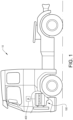
- a vehicle 10 in the form of a truck comprising a prime mover 100 in the form of an internal combustion engine arrangement 100.
- the internal combustion engine arrangement 100 may be propelled by e.g. a conventional fuel such as diesel, although other alternatives are conceivable.
- the internal combustion engine 100 is preferably operated in a four stroke fashion, i.e. operated by an intake stroke, a compression stroke, a combustion stroke, and an exhaust stroke.
- the internal combustion engine arrangement 100 also comprises a control unit 400 for controlling operation of the internal combustion engine arrangement 100.
- the control unit 400 is thus preferably arranged to control inlet and outlet valves (depicted in Figs. 2a - 3c ) and/or to control operation of the cam phaser (200 in Figs. 4a - 4b ) described below.
- the combustion cylinder 102 comprises a reciprocating piston 104 movable between a bottom dead center 101 (BDC) and a top dead center 103 (TDC) within the combustion cylinder 102.
- BDC 101 is the position of the turning point when the downward motion of the piston 104 is changed to the upward motion within the combustion cylinder 102, which turning point is indicated by arrow 105.
- the piston 104 is also indicated in dashed lines at the BDC 101.
- the TDC 103 is the position of the turning point when the upward motion of the piston 104 is changed to the downward motion within the combustion cylinder 102.
- the piston 104 is also indicated in dashed lines at the TDC 103.
- the internal combustion engine arrangement 100 also comprises an inlet valve 106 operable between an open position and a closed position, wherein gas, preferably in the form of ambient air, is directed into a combustion chamber 109 of the combustion cylinder 102 when the inlet valve 106 is positioned in the open position.
- the inlet valve 106 is preferably arranged in the open position during the intake stroke when the piston 104 moves downwards from the TDC towards the BDC.
- ambient air is delivered into combustion chamber.
- the internal combustion engine arrangement 100 also comprises an outlet valve 112 which is operable between an open position and a closed position. The outlet valve 112 is closed during the intake stroke, the compression stroke and the combustion stroke.
- the outlet valve 112 is preferably arranged in the open position after the combustion stroke when the piston moves in the upwards direction from the BDC 101 towards the TDC 103.
- the inlet valve 106 as well as the outlet valve 112 may be controlled by means of e.g. a pressurized fluid which forces the respective valve to be opened and closed.
- a pressurized fluid is preferably a high pressure gas, such as e.g. high pressure air. Opening and closing of such valve is preferably controlled by the above described control unit 400.
- the control unit 400 sends control signals for controlling delivery of high pressure gas to open the respective valve.
- the inlet valve 106 and the outlet valve 112 may be connected to a respective cam shaft for controlling operation thereof.
- the normal operation may relate to a steady state operation of the internal combustion engine arrangement 100, where the internal combustion engine arrangement 100 is operated relatively constant during a period of time.
- the steady state operation may thus relate to the energy provided into the system and the energy delivered out from the system after combustion, which should be substantially the same during steady state operation.
- Fig. 2a illustrates the intake stroke for the internal combustion engine arrangement 100.
- the inlet valve 106 is thus arranged in the open position during the downward motion from the TDC 103 towards the BDC 101.
- the inlet valve 106 is positioned in the closed position, as indicated by the arrow indicating the closing motion of the inlet valve 106, such that no further air is directed into the combustion chamber 109 of the combustion cylinder 102 when the piston travels the distance 110 to the BDC 101.
- the distance 110 before the piston reaches the BDC may be between 20 - 60 crank angle degrees.
- the air inside the combustion chamber 109 will be expanded when the piston moves downwards and the inlet valve 106 is closed.
- the compression stage is initiated, where after combustion and exhaust takes place according to normal four stroke principle. Accordingly, the internal combustion engine arrangement is in Figs. 2a - 2b operated according to the so-called early Miller approach.
- Figs. 2c in which an approach is depicted for increasing the volumetric efficiency of the combustion cylinder 102.
- the transient load situations may, for example, relate to situations where the internal combustion engine arrangement 100 is in sudden need of additional power/boost for operating the vehicle satisfactory at the specific situation.
- the inlet valve 106 is controlled to be maintained in the open position until the piston 104 reaches the BDC 101. This may be controlled by the control unit 400 depicted in Fig. 1 . Accordingly, when the required volumetric efficiency is increased, the inlet valve 106 can be controlled to be positioned in the open position during the movement of the piston 104 from the TDC 103 to the BDC 101.
- the closing motion of the inlet valve 106 in Fig. 2c is indicated by the arrow arranging the inlet valve in the closed position.
- the internal combustion engine arrangement 100 can be arranged to be controlled according to the illustration in Fig. 2c for a relatively short period of time until the internal combustion engine arrangement 100 is again operated in the steady state operation.
- the inlet valve 106 as well as the outlet valve 112 are controlled by means of a respective cam shaft 108, 114.
- a cam lobe 122 of the cam shaft cyclically pushes the respective valve to be arranged in the open position.
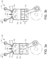
- Cam shafts are well known and need no further description. An example embodiment when controlling the inlet valve 106 and the outlet valve 112 by means of a respective cam shaft will now be described with reference to Figs. 3a - 3d .
- the internal combustion engine 100 is in Figs. 3a - 3b operated according to the early Miller principle.
- the inlet cam shaft 108 which is connected to the inlet valve 106 is arranged in such a way as to close the inlet valve 106 during the intake stroke when the piston 104 is, during the downward motion, located the distance 110 from the BDC.
- the inlet cam shaft 108 controls the inlet valve 106 to be positioned in the open position from the TDC 103 until the piston is located at the distance 110 from the BDC.
- the cam shaft 108 is rotated counter clockwise around a cam shaft axis 111 during normal operation.
- Figs. 3c - 3d illustrate the operation of the combustion cylinder 102 when there is a demand for increased volumetric efficiency of the combustion cylinder 102.
- the inlet valve 106 of the embodiment depicted in Fig. 3c is maintained in the open position until the piston 104 reaches the BDC 101. This is preferably achieved by rotating the cam shaft 108 in a clockwise direction relative the cam shaft axis 111 such that the closing of the inlet valve 106 is delayed when the cam shaft rotates in the counter clockwise direction.
- Rotation of the inlet cam shaft 108 relative the cam shaft axis 111 is preferably performed by means of a so-called cam phaser. An example embodiment of such cam phaser 200 is described below with reference to Figs. 4a .
- the inlet valve 108 As the inlet cam shaft 108 is rotated in the clockwise direction, the inlet valve 108 is not be opened at the TDC 103 as performed during the normal operation depicted in Figs.3a - 3b .
- the opening of the inlet valve 106 is thus made at a corresponding distance 310 after the piston 104 has left the TDC 103, which is indicated in Fig. 3d .
- the opening and closing of the inlet valve 106 depicted in Figs. 3c - 3d is hereby postponed in comparison to the opening and closing of the inlet valve 106 during the early Miller operation as depicted in Figs. 3a - 3b .
- the distance 310 from the TDC 103 may correspond to the above described distance 110 from the BDC 101 during the early Miller operation.
- the inlet cam shaft 108 is preferably designed for successively opening the inlet valve 106 at an earlier point in time, i.e. successively opening the inlet valve 106 before the piston 104 has travelled the full distance 310 from the TDC in Fig. 3d .
- This can be achieved by adding a ramp 120 (see zoom-in portion of Fig. 3c ) to the left side of the cam lobe 122.
- the ramp 120 will initiate opening of the inlet valve 106 at an earlier point in time.
- the specific side of the ramp 120 relative the cam lobe 122 is naturally dependent on the rotational direction of the cam shaft 108.
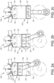
- Figs. 4a - 4b illustrate a cam phaser 200 according to an embodiment of the invention.
- the cam phaser 200 is thus connected to the inlet cam shaft 108 for controllably rotating the inlet cam shaft 108.
- the cam phaser 200 in Figs. 4a - 4b comprises a phaser piston 202 which is movable within a pressure chamber 204 of the cam phaser 200.
- the phaser piston 202 is in turn connected to the inlet cam shaft 108.
- the cam phaser 200 is positioning the inlet cam shaft 108 in the neutral position for operating the combustion cylinder 102 as depicted in Figs. 3a - 3b .
- the phaser piston 202 is however movable to the left and right as depicted with the double sided arrows 205.
- the phaser piston 202, and thus the inlet cam shaft 108 is moved in the clockwise direction. This is preferably performed by supplying high pressure air to an inlet 207 of the pressure chamber 204.
- Fig. 5 is a flow chart of a method for controlling the above described internal combustion engine arrangement 100 according to an example embodiment.
- a signal is received S1, which signal is indicative of an operating mode of the internal combustion engine arrangement 100.
- the signal may thus relate to how the internal combustion engine arrangement 100 is operated, such as e.g. operated in the above described steady state operation or in a transient operating mode.
- a required volumetric efficiency of the combustion cylinder 102 for operating the internal combustion engine arrangement 100 in the operating mode can thereafter be determined S2. It is thereafter determined if the required volumetric efficiency is higher than the volumetric efficiency of the combustion cylinder 102 during normal operation.
- the inlet valve 106 is controlled S3 to be arranged in the open position until the piston reaches the BDC 101.
- the inlet valve 106 is controlled S4 to be operated according to the early Miller approach, i.e. to be arranged in the closed position a distance 110 before the piston 104 reaches the BDC 101, whereby the method starts over.
- the step of controlling the inlet valve 106 to be maintained in the open position until the piston reaches the BDC 101 it is determined if the required volumetric efficiency is higher than the volumetric efficiency of the combustion cylinder 102 during normal operation. If the required volumetric efficiency is higher, the internal combustion engine arrangement 100 is continued to be controlled S3 such that the inlet valve 106 is arranged in the open position until the piston reaches the BDC 101. On the other hand, if the required volumetric efficiency is lower, or the same, as the volumetric efficiency of the combustion cylinder 102 during normal operation, the internal combustion engine arrangement 100 is returned to be controlled according to the early Miller approach, whereby the method starts over.
- the internal combustion engine arrangement is normally operated according to the step indicated by S4 in Fig. 5 , i.e. according to the early Miller approach such that the inlet valve is closed a distance before the piston reaches the BDC.
- the inlet valve is maintained in the open position until the piston reaches the BDC.
Landscapes
- Engineering & Computer Science (AREA)
- Mechanical Engineering (AREA)
- General Engineering & Computer Science (AREA)
- Chemical & Material Sciences (AREA)
- Combustion & Propulsion (AREA)
- Valve Device For Special Equipments (AREA)
- Output Control And Ontrol Of Special Type Engine (AREA)
Claims (15)
- Verfahren zur Steuerung einer Verbrennungsmotoranordnung (100), wobei die Verbrennungsmotoranordnung umfasst:- einen Verbrennungszylinder (102), in dem ein Hubkolben (104) untergebracht ist, der zwischen einem unteren Totpunkt (101) und einem oberen Totpunkt (13) innerhalb des Verbrennungszylinders bewegbar ist;- ein Einlassventil (106), das zwischen einer offenen Position und einer geschlossenen Position betätigbar ist, um den Luftstrom in den Verbrennungszylinder (102) zu steuern;- eine steuerbare Einlassnockenwelle (108), die mit dem Einlassventil verbunden ist, wobei die Einlassnockenwelle (108) dazu eingerichtet ist, während des normalen Betriebs der Verbrennungsmotoranordnung das Einlassventil (106) von der geschlossenen Position zur offenen Position zu positionieren, wenn der Kolben den oberen Totpunkt erreicht, und das Einlassventil in der geschlossenen Position bei einem vorgegebenen Kurbelwinkelgrad zu positionieren, bevor der Kolben den unteren Totpunkt erreicht; und- einen Nockenversteller (200), der mit der Einlassnockenwelle (108) verbunden ist, wobei der Nockenversteller dazu eingerichtet ist, die Ventileinstellung des Einlassventils variabel zu steuern, wobei das Verfahren die folgenden Schritte umfasst:falls der erforderliche volumetrische Wirkungsgrad höher als ein volumetrischer Wirkungsgrad des Verbrennungszylinders während des normalen Betriebs der Verbrennungsmotoranordnung ist:- Empfangen (S1) eines Signals, das für eine Betriebsart der Verbrennungsmotoranordnung indikativ ist;- Bestimmen (S2) eines erforderlichen volumetrischen Wirkungsgrads des Verbrennungszylinders zum Betreiben der Verbrennungsmotoranordnung in der Betriebsart; und- Steuern (S3), unter Verwendung des Nockenverstellers, der mit der Einlassnockenwelle verbunden ist, um das Einlassventil bei der gleichen Anzahl von Kurbelwinkelgraden vom oberen Totpunkt zu öffnen, wie die Anzahl von Kurbelwinkelgraden vom unteren Totpunkt, wenn das Einlassventil geschlossen wird, wenn die Verbrennungsmotoranordnung während des normalen Betriebs betrieben wird, um einen Zeitabschnitt, in dem das Einlassventil in der offenen Position angeordnet ist, im Vergleich zum normalen Betrieb hinauszuschieben, und um das Einlassventil in der offenen Position zu halten, bis der Kolben den unteren Totpunkt (101) erreicht, wobei das Einlassventil so gesteuert wird, dass es geschlossen wird, wenn der Kolben den unteren Totpunkt erreicht hat.
- Verfahren nach Anspruch 1, wobei der Verbrennungsmotor während seines normalen Betriebs in einem stationären Zustand betrieben wird.
- Verfahren nach einem der vorhergehenden Ansprüche, wobei die Verbrennungsmotoranordnung ferner ein Auslassventil umfasst, das zwischen einer offenen Position und einer geschlossenen Position betätigbar ist, um den Strom von Verbrennungsgasen aus dem Verbrennungszylinder hinaus zu steuern, wobei das Auslassventil nach einer Verbrennungsphase in der offenen Position angeordnet ist, wenn sich der Kolben während des normalen Betriebs der Verbrennungsmotoranordnung vom unteren Totpunkt zum oberen Totpunkt bewegt, sowie wenn der erforderliche volumetrische Wirkungsgrad höher als der volumetrische Wirkungsgrad des normalen Betriebs des Verbrennungsmotors ist.
- Verfahren nach einem der vorhergehenden Ansprüche, das ferner den folgenden Schritt umfasst:- Bestimmen, dass der erforderliche volumetrische Wirkungsgrad im Vergleich zum normalen Betrieb der Verbrennungsmotoranordnung höher ist, falls die Verbrennungsmotoranordnung in der Betriebsart eine erhöhte Motorleistung verlangt.
- Verfahren nach einem der vorhergehenden Ansprüche, das ferner den folgenden Schritt umfasst:- Bestimmen, dass der erforderliche volumetrische Wirkungsgrad im Vergleich zum normalen Betrieb der Verbrennungsmotoranordnung höher ist, falls die Verbrennungsmotoranordnung in der Betriebsart in einem transienten Zustand betrieben wird.
- Verfahren nach einem der vorhergehenden Ansprüche, das ferner den folgenden Schritt umfasst- Bestimmen, dass der erforderliche volumetrische Wirkungsgrad im Vergleich zum normalen Betrieb der Verbrennungsmotoranordnung höher ist, falls die Verbrennungsmotoranordnung in der Betriebsart in einem Motorstartzustand betrieben wird.
- Verfahren nach einem der vorhergehenden Ansprüche, wobei der Schritt des Steuerns der Einlassnockenwelle den folgenden Schritt umfasst:- Steuern des Nockenverstellers, um die Einlassnockenwelle zu drehen, um das Einlassventil im offenen Zustand zu halten, bis der Kolben den unteren Totpunkt erreicht, wenn der erforderliche volumetrische Wirkungsgrad höher als der volumetrische Wirkungsgrad des Verbrennungszylinders während des normalen Betriebs der Verbrennungsmotoranordnung ist.
- Verfahren nach einem der vorhergehenden Ansprüche, das ferner den folgenden Schritt umfasst:- Steuern der Einlassnockenwelle, um das Einlassventil allmählich von der geschlossenen Position zur offenen Position zu bewegen, wenn sich der Kolben vom oberen Totpunkt zum unteren Totpunkt hin bewegt, wenn der Verbrennungsmotor in der Betriebsart betrieben wird.
- Verbrennungsmotoranordnung (100), welche umfasst: einen Verbrennungszylinder (102), in dem ein Hubkolben (104) untergebracht ist, der zwischen einem unteren Totpunkt (101) und einem oberen Totpunkt (103) innerhalb des Verbrennungszylinders bewegbar ist; ein Einlassventil (106), das zwischen einer offenen und einer geschlossenen Position betätigbar ist, um den Luftstrom in den Verbrennungszylinder zu steuern; eine steuerbare Einlassnockenwelle (108), die mit dem Einlassventil verbunden ist, wobei die Einlassnockenwelle (108) dazu eingerichtet ist, während des normalen Betriebs der Verbrennungsmotoranordnung das Einlassventil (106) von der geschlossenen Position zur offenen Position zu positionieren, wenn der Kolben den oberen Totpunkt erreicht, und das Einlassventil in der geschlossenen Position bei einem vorgegebenen Kurbelwinkelgrad zu positionieren, bevor der Kolben den unteren Totpunkt erreicht; und einen Nockenversteller (200), der mit der Einlassnockenwelle (108) verbunden ist, wobei der Nockenversteller dazu eingerichtet ist, die Ventileinstellung des Einlassventils variabel zu steuern, wobei die Verbrennungsmotoranordnung ferner eine Steuereinheit umfasst, die dafür ausgelegt ist:- ein Signal zu empfangen, das für eine Betriebsart der Verbrennungsmotoranordnung indikativ ist;- einen erforderlichen volumetrischen Wirkungsgrad des Verbrennungszylinders zum Betreiben der Verbrennungsmotoranordnung in der Betriebsart zu bestimmen; und falls der erforderliche volumetrische Wirkungsgrad höher als ein volumetrischer Wirkungsgrad des Verbrennungszylinders während des normalen Betriebs der Verbrennungsmotoranordnung ist, die Steuereinheit ferner dafür ausgelegt ist:- den Nockenversteller, der mit der Einlassnockenwelle verbunden ist, zu steuern, um das Einlassventil bei der gleichen Anzahl von Kurbelwinkelgraden vom oberen Totpunkt zu öffnen, wie die Anzahl von Kurbelwinkelgraden vom unteren Totpunkt, wenn das Einlassventil geschlossen wird, wenn die Verbrennungsmotoranordnung während des normalen Betriebs betrieben wird, um einen Zeitabschnitt, in dem das Einlassventil in der offenen Position angeordnet ist, im Vergleich zum normalen Betrieb hinauszuschieben, und um das Einlassventil in der offenen Position zu halten, bis der Kolben den unteren Totpunkt erreicht, wobei das Einlassventil so gesteuert wird, dass es geschlossen wird, wenn der Kolben den unteren Totpunkt erreicht hat.
- Verbrennungsmotoranordnung (100) nach Anspruch 9, wobei der Nockenversteller dazu eingerichtet ist, die Einlassnockenwelle zu steuern, um das Einlassventil (106) in einem Abstand (110) von mindestens 20 Kurbelwinkelgraden, bevor der Kolben den unteren Totpunkt während des normalen Betriebs des Verbrennungsmotors erreicht hat, in die geschlossene Position zu positionieren.
- Verbrennungsmotoranordnung nach einem der Ansprüche 9 - 10, welche ferner umfasst: ein Auslassventil (112) zur steuerbaren Abgabe von im Verbrennungszylinder erzeugten Verbrennungsgasen aus dem Verbrennungszylinder; und eine Auslassnockenwelle (114), die mit dem Auslassventil verbunden ist, zum Steuern des Auslassventils zwischen einer offenen Position und einer geschlossenen Position.
- Verbrennungsmotoranordnung nach einem der Ansprüche 9 - 11, wobei der Nockenversteller (200) ein fluidisch gesteuerter Nockenversteller ist, der einen mit der Einlassnockenwelle (108) verbundenen Verstellerkolben (202) umfasst, wobei der Verstellerkolben (202) in einer Druckkammer (204) des Nockenverstellers (200) positioniert ist, wobei der Nockenversteller (200) dazu eingerichtet ist, druckbeaufschlagtes Fluid in der Druckkammer (204) zum Steuern der Position der Einlassnockenwelle zu empfangen.
- Fahrzeug, welches eine Verbrennungsmotoranordnung nach einem der Ansprüche 9 - 12 umfasst.
- Computerprogramm, welches Programmcodemittel zum Durchführen der Schritte nach einem der Ansprüche 1 - 8, wenn das Programm auf der Steuereinheit der Verbrennungsmotoranordnung nach einem der Ansprüche 9 - 12 ausgeführt wird, umfasst.
- Computerlesbares Medium mit einem Computerprogramm, das Programmmittel zum Durchführen der Schritte nach einem der Ansprüche 1 - 8, wenn die Programmmittel auf der Steuereinheit der Verbrennungsmotoranordnung nach einem der Ansprüche 9 - 12 ausgeführt werden, umfasst.
Applications Claiming Priority (1)
| Application Number | Priority Date | Filing Date | Title |
|---|---|---|---|
| PCT/EP2017/080765 WO2019105538A1 (en) | 2017-11-29 | 2017-11-29 | Method for controlling an internal combustion engine arrangement |
Publications (3)
| Publication Number | Publication Date |
|---|---|
| EP3717762A1 EP3717762A1 (de) | 2020-10-07 |
| EP3717762B1 EP3717762B1 (de) | 2022-09-14 |
| EP3717762B2 true EP3717762B2 (de) | 2025-06-11 |
Family
ID=60480329
Family Applications (1)
| Application Number | Title | Priority Date | Filing Date |
|---|---|---|---|
| EP17804910.2A Active EP3717762B2 (de) | 2017-11-29 | 2017-11-29 | Verfahren zur steuerung einer verbrennungsmotoranordnung |
Country Status (4)
| Country | Link |
|---|---|
| US (1) | US11852045B2 (de) |
| EP (1) | EP3717762B2 (de) |
| CN (1) | CN111448378B (de) |
| WO (1) | WO2019105538A1 (de) |
Families Citing this family (1)
| Publication number | Priority date | Publication date | Assignee | Title |
|---|---|---|---|---|
| EP3717762B2 (de) | 2017-11-29 | 2025-06-11 | Volvo Truck Corporation | Verfahren zur steuerung einer verbrennungsmotoranordnung |
Family Cites Families (23)
| Publication number | Priority date | Publication date | Assignee | Title |
|---|---|---|---|---|
| US5419301A (en) * | 1994-04-14 | 1995-05-30 | Ford Motor Company | Adaptive control of camless valvetrain |
| US6276321B1 (en) | 2000-01-11 | 2001-08-21 | Delphi Technologies, Inc. | Cam phaser having a torsional bias spring to offset retarding force of camshaft friction |
| DE10122775A1 (de) * | 2000-05-18 | 2001-11-22 | Ford Global Tech Inc | Hybrider Motor und Verfahren zu dessen Taktsteuerung |
| JP3815233B2 (ja) | 2001-02-27 | 2006-08-30 | 日産自動車株式会社 | 内燃機関の吸気制御装置 |
| JP3912147B2 (ja) * | 2002-03-15 | 2007-05-09 | 日産自動車株式会社 | 内燃機関の可変動弁装置 |
| JP4416377B2 (ja) | 2002-05-16 | 2010-02-17 | 日産自動車株式会社 | 内燃機関の制御装置 |
| US6705259B1 (en) | 2002-12-10 | 2004-03-16 | Delphi Technologies, Inc. | 3-step cam-profile-switching roller finger follower |
| JP4186613B2 (ja) | 2002-12-16 | 2008-11-26 | 日産自動車株式会社 | 内燃機関の吸気制御装置 |
| JP4066851B2 (ja) * | 2003-03-03 | 2008-03-26 | トヨタ自動車株式会社 | 可変サイクルエンジンおよび運転モードの切り替え方法 |
| DE102004026405B4 (de) | 2004-05-29 | 2006-09-07 | Bayerische Motoren Werke Ag | Verfahren zum Betreiben einer Brennkraftmaschine |
| JP4529713B2 (ja) * | 2005-02-08 | 2010-08-25 | トヨタ自動車株式会社 | 内燃機関の制御方法 |
| US7540270B2 (en) * | 2007-04-24 | 2009-06-02 | Gm Global Technology Operations, Inc. | Method and apparatus for controlling combustion mode transitions in an internal combustion engine |
| JP4989523B2 (ja) | 2008-03-06 | 2012-08-01 | 日立オートモティブシステムズ株式会社 | 内燃機関の可変動弁システム及び内燃機関の制御装置 |
| JP5104474B2 (ja) * | 2008-03-31 | 2012-12-19 | マツダ株式会社 | 内燃機関の制御方法および同装置 |
| ATE523676T1 (de) | 2008-06-18 | 2011-09-15 | Caterpillar Motoren Gmbh & Co | Vorrichtung zur steuerung des betriebs eines verbrennungsmotors |
| JP2010138737A (ja) | 2008-12-10 | 2010-06-24 | Hitachi Automotive Systems Ltd | 内燃機関の可変動弁装置及び該可変動弁装置のコントローラ |
| EP2508737B1 (de) * | 2009-12-04 | 2015-01-21 | Toyota Jidosha Kabushiki Kaisha | Verbrennungsmotor mit funkenzündung |
| US20120125276A1 (en) | 2010-11-22 | 2012-05-24 | Caterpillar Inc. | Four stroke internal combustion engine having variable valve timing and method |
| DE102012014713A1 (de) | 2012-07-25 | 2014-01-30 | Volkswagen Aktiengesellschaft | Verfahren zum Betreiben eines Verbrennungsmotors |
| US9222429B2 (en) | 2013-02-14 | 2015-12-29 | Caterpillar Inc. | Engine control system having a cam phaser |
| DE102014204492A1 (de) | 2014-03-12 | 2015-10-01 | Volkswagen Aktiengesellschaft | Kraftfahrzeug, Steuergerät und Verfahren zum Steuern einer Phasenlage einer Nockenwelle |
| US9926856B2 (en) * | 2015-08-14 | 2018-03-27 | Cummins Inc. | Cooperative cam phaser and air throttle control |
| EP3717762B2 (de) | 2017-11-29 | 2025-06-11 | Volvo Truck Corporation | Verfahren zur steuerung einer verbrennungsmotoranordnung |
-
2017
- 2017-11-29 EP EP17804910.2A patent/EP3717762B2/de active Active
- 2017-11-29 WO PCT/EP2017/080765 patent/WO2019105538A1/en not_active Ceased
- 2017-11-29 US US16/767,983 patent/US11852045B2/en active Active
- 2017-11-29 CN CN201780097156.8A patent/CN111448378B/zh active Active
Also Published As
| Publication number | Publication date |
|---|---|
| US11852045B2 (en) | 2023-12-26 |
| EP3717762A1 (de) | 2020-10-07 |
| WO2019105538A1 (en) | 2019-06-06 |
| CN111448378B (zh) | 2022-07-22 |
| CN111448378A (zh) | 2020-07-24 |
| US20200362733A1 (en) | 2020-11-19 |
| EP3717762B1 (de) | 2022-09-14 |
Similar Documents
| Publication | Publication Date | Title |
|---|---|---|
| US10830159B2 (en) | Valve-actuating device for varying the valve lift | |
| KR101633042B1 (ko) | 조기 배기 밸브 개방을 위한 엔진 브레이킹 메커니즘을 사용한 엔진 시스템 및 작동 방법 | |
| EP2325460A1 (de) | Kompaktes Totgangsystem für variable Ventilbetätigung | |
| KR20100096021A (ko) | 가변 밸브 기어를 구비한 내연 기관 | |
| CN102486105B (zh) | 用电动cvvt控制改善gdi发动机的启动性能的方法 | |
| CN109404141B (zh) | 一种可变气门控制装置及方法 | |
| US6237559B1 (en) | Cylinder deactivation via exhaust valve deactivation and intake cam retard | |
| WO2009151352A1 (en) | Late miller internal combustion engine | |
| KR102203587B1 (ko) | 내연 기관의 작동 | |
| EP3717762B2 (de) | Verfahren zur steuerung einer verbrennungsmotoranordnung | |
| CN110087929A (zh) | 用于运行驱动系统的方法、驱动系统和机动车 | |
| EP4058665B1 (de) | Verfahren zur steuerung einer ventilanordnung | |
| JP4539538B2 (ja) | エネルギ回収装置 | |
| CN112400055A (zh) | 用于在发动机制动操作中操作尤其是机动车的内燃机的方法 | |
| EP3184779B1 (de) | System zur variablen betätigung eines ventils eines verbrennungsmotors | |
| EP3444467B1 (de) | Steuerungssystem für verbrennungsmotoren | |
| CN102128092A (zh) | 包括进气真空度管理系统的发动机 | |
| CN107110032A (zh) | 柴油发动机以及用于使柴油发动机运行的方法 | |
| CN107110042A (zh) | 柴油发动机以及用于起动柴油发动机的方法 | |
| CN102817663A (zh) | 一种连续可变配气定时机构 | |
| US11136926B2 (en) | Method for operating a reciprocating piston internal combustion engine | |
| US10677173B2 (en) | Control system for internal combustion engines | |
| JP2021025512A (ja) | エンジンシステム | |
| JP2005207261A (ja) | 可変ivc出力制御動弁機構 | |
| JP2012202294A (ja) | 可変圧縮比機構を備える内燃機関 |
Legal Events
| Date | Code | Title | Description |
|---|---|---|---|
| STAA | Information on the status of an ep patent application or granted ep patent |
Free format text: STATUS: UNKNOWN |
|
| STAA | Information on the status of an ep patent application or granted ep patent |
Free format text: STATUS: THE INTERNATIONAL PUBLICATION HAS BEEN MADE |
|
| PUAI | Public reference made under article 153(3) epc to a published international application that has entered the european phase |
Free format text: ORIGINAL CODE: 0009012 |
|
| STAA | Information on the status of an ep patent application or granted ep patent |
Free format text: STATUS: REQUEST FOR EXAMINATION WAS MADE |
|
| 17P | Request for examination filed |
Effective date: 20200522 |
|
| AK | Designated contracting states |
Kind code of ref document: A1 Designated state(s): AL AT BE BG CH CY CZ DE DK EE ES FI FR GB GR HR HU IE IS IT LI LT LU LV MC MK MT NL NO PL PT RO RS SE SI SK SM TR |
|
| AX | Request for extension of the european patent |
Extension state: BA ME |
|
| DAV | Request for validation of the european patent (deleted) | ||
| DAX | Request for extension of the european patent (deleted) | ||
| GRAP | Despatch of communication of intention to grant a patent |
Free format text: ORIGINAL CODE: EPIDOSNIGR1 |
|
| STAA | Information on the status of an ep patent application or granted ep patent |
Free format text: STATUS: GRANT OF PATENT IS INTENDED |
|
| INTG | Intention to grant announced |
Effective date: 20211105 |
|
| GRAJ | Information related to disapproval of communication of intention to grant by the applicant or resumption of examination proceedings by the epo deleted |
Free format text: ORIGINAL CODE: EPIDOSDIGR1 |
|
| STAA | Information on the status of an ep patent application or granted ep patent |
Free format text: STATUS: REQUEST FOR EXAMINATION WAS MADE |
|
| INTC | Intention to grant announced (deleted) | ||
| GRAP | Despatch of communication of intention to grant a patent |
Free format text: ORIGINAL CODE: EPIDOSNIGR1 |
|
| STAA | Information on the status of an ep patent application or granted ep patent |
Free format text: STATUS: GRANT OF PATENT IS INTENDED |
|
| INTG | Intention to grant announced |
Effective date: 20220411 |
|
| GRAS | Grant fee paid |
Free format text: ORIGINAL CODE: EPIDOSNIGR3 |
|
| GRAA | (expected) grant |
Free format text: ORIGINAL CODE: 0009210 |
|
| STAA | Information on the status of an ep patent application or granted ep patent |
Free format text: STATUS: THE PATENT HAS BEEN GRANTED |
|
| AK | Designated contracting states |
Kind code of ref document: B1 Designated state(s): AL AT BE BG CH CY CZ DE DK EE ES FI FR GB GR HR HU IE IS IT LI LT LU LV MC MK MT NL NO PL PT RO RS SE SI SK SM TR |
|
| REG | Reference to a national code |
Ref country code: GB Ref legal event code: FG4D |
|
| REG | Reference to a national code |
Ref country code: CH Ref legal event code: EP |
|
| REG | Reference to a national code |
Ref country code: DE Ref legal event code: R096 Ref document number: 602017061832 Country of ref document: DE |
|
| REG | Reference to a national code |
Ref country code: IE Ref legal event code: FG4D |
|
| REG | Reference to a national code |
Ref country code: AT Ref legal event code: REF Ref document number: 1518823 Country of ref document: AT Kind code of ref document: T Effective date: 20221015 |
|
| REG | Reference to a national code |
Ref country code: NL Ref legal event code: FP |
|
| REG | Reference to a national code |
Ref country code: LT Ref legal event code: MG9D |
|
| PG25 | Lapsed in a contracting state [announced via postgrant information from national office to epo] |
Ref country code: SE Free format text: LAPSE BECAUSE OF FAILURE TO SUBMIT A TRANSLATION OF THE DESCRIPTION OR TO PAY THE FEE WITHIN THE PRESCRIBED TIME-LIMIT Effective date: 20220914 Ref country code: RS Free format text: LAPSE BECAUSE OF FAILURE TO SUBMIT A TRANSLATION OF THE DESCRIPTION OR TO PAY THE FEE WITHIN THE PRESCRIBED TIME-LIMIT Effective date: 20220914 Ref country code: NO Free format text: LAPSE BECAUSE OF FAILURE TO SUBMIT A TRANSLATION OF THE DESCRIPTION OR TO PAY THE FEE WITHIN THE PRESCRIBED TIME-LIMIT Effective date: 20221214 Ref country code: LV Free format text: LAPSE BECAUSE OF FAILURE TO SUBMIT A TRANSLATION OF THE DESCRIPTION OR TO PAY THE FEE WITHIN THE PRESCRIBED TIME-LIMIT Effective date: 20220914 Ref country code: LT Free format text: LAPSE BECAUSE OF FAILURE TO SUBMIT A TRANSLATION OF THE DESCRIPTION OR TO PAY THE FEE WITHIN THE PRESCRIBED TIME-LIMIT Effective date: 20220914 Ref country code: FI Free format text: LAPSE BECAUSE OF FAILURE TO SUBMIT A TRANSLATION OF THE DESCRIPTION OR TO PAY THE FEE WITHIN THE PRESCRIBED TIME-LIMIT Effective date: 20220914 |
|
| REG | Reference to a national code |
Ref country code: AT Ref legal event code: MK05 Ref document number: 1518823 Country of ref document: AT Kind code of ref document: T Effective date: 20220914 |
|
| PG25 | Lapsed in a contracting state [announced via postgrant information from national office to epo] |
Ref country code: HR Free format text: LAPSE BECAUSE OF FAILURE TO SUBMIT A TRANSLATION OF THE DESCRIPTION OR TO PAY THE FEE WITHIN THE PRESCRIBED TIME-LIMIT Effective date: 20220914 Ref country code: GR Free format text: LAPSE BECAUSE OF FAILURE TO SUBMIT A TRANSLATION OF THE DESCRIPTION OR TO PAY THE FEE WITHIN THE PRESCRIBED TIME-LIMIT Effective date: 20221215 |
|
| PG25 | Lapsed in a contracting state [announced via postgrant information from national office to epo] |
Ref country code: SM Free format text: LAPSE BECAUSE OF FAILURE TO SUBMIT A TRANSLATION OF THE DESCRIPTION OR TO PAY THE FEE WITHIN THE PRESCRIBED TIME-LIMIT Effective date: 20220914 Ref country code: RO Free format text: LAPSE BECAUSE OF FAILURE TO SUBMIT A TRANSLATION OF THE DESCRIPTION OR TO PAY THE FEE WITHIN THE PRESCRIBED TIME-LIMIT Effective date: 20220914 Ref country code: PT Free format text: LAPSE BECAUSE OF FAILURE TO SUBMIT A TRANSLATION OF THE DESCRIPTION OR TO PAY THE FEE WITHIN THE PRESCRIBED TIME-LIMIT Effective date: 20230116 Ref country code: ES Free format text: LAPSE BECAUSE OF FAILURE TO SUBMIT A TRANSLATION OF THE DESCRIPTION OR TO PAY THE FEE WITHIN THE PRESCRIBED TIME-LIMIT Effective date: 20220914 Ref country code: CZ Free format text: LAPSE BECAUSE OF FAILURE TO SUBMIT A TRANSLATION OF THE DESCRIPTION OR TO PAY THE FEE WITHIN THE PRESCRIBED TIME-LIMIT Effective date: 20220914 Ref country code: AT Free format text: LAPSE BECAUSE OF FAILURE TO SUBMIT A TRANSLATION OF THE DESCRIPTION OR TO PAY THE FEE WITHIN THE PRESCRIBED TIME-LIMIT Effective date: 20220914 |
|
| PG25 | Lapsed in a contracting state [announced via postgrant information from national office to epo] |
Ref country code: SK Free format text: LAPSE BECAUSE OF FAILURE TO SUBMIT A TRANSLATION OF THE DESCRIPTION OR TO PAY THE FEE WITHIN THE PRESCRIBED TIME-LIMIT Effective date: 20220914 Ref country code: PL Free format text: LAPSE BECAUSE OF FAILURE TO SUBMIT A TRANSLATION OF THE DESCRIPTION OR TO PAY THE FEE WITHIN THE PRESCRIBED TIME-LIMIT Effective date: 20220914 Ref country code: IS Free format text: LAPSE BECAUSE OF FAILURE TO SUBMIT A TRANSLATION OF THE DESCRIPTION OR TO PAY THE FEE WITHIN THE PRESCRIBED TIME-LIMIT Effective date: 20230114 Ref country code: EE Free format text: LAPSE BECAUSE OF FAILURE TO SUBMIT A TRANSLATION OF THE DESCRIPTION OR TO PAY THE FEE WITHIN THE PRESCRIBED TIME-LIMIT Effective date: 20220914 |
|
| REG | Reference to a national code |
Ref country code: DE Ref legal event code: R026 Ref document number: 602017061832 Country of ref document: DE |
|
| PLBI | Opposition filed |
Free format text: ORIGINAL CODE: 0009260 |
|
| PLAB | Opposition data, opponent's data or that of the opponent's representative modified |
Free format text: ORIGINAL CODE: 0009299OPPO |
|
| PLAX | Notice of opposition and request to file observation + time limit sent |
Free format text: ORIGINAL CODE: EPIDOSNOBS2 |
|
| PG25 | Lapsed in a contracting state [announced via postgrant information from national office to epo] |
Ref country code: MC Free format text: LAPSE BECAUSE OF FAILURE TO SUBMIT A TRANSLATION OF THE DESCRIPTION OR TO PAY THE FEE WITHIN THE PRESCRIBED TIME-LIMIT Effective date: 20220914 Ref country code: AL Free format text: LAPSE BECAUSE OF FAILURE TO SUBMIT A TRANSLATION OF THE DESCRIPTION OR TO PAY THE FEE WITHIN THE PRESCRIBED TIME-LIMIT Effective date: 20220914 |
|
| REG | Reference to a national code |
Ref country code: CH Ref legal event code: PL |
|
| 26 | Opposition filed |
Opponent name: SCANIA CV AB Effective date: 20230613 |
|
| R26 | Opposition filed (corrected) |
Opponent name: SCANIA CV AB Effective date: 20230613 |
|
| REG | Reference to a national code |
Ref country code: BE Ref legal event code: MM Effective date: 20221130 |
|
| PG25 | Lapsed in a contracting state [announced via postgrant information from national office to epo] |
Ref country code: LI Free format text: LAPSE BECAUSE OF NON-PAYMENT OF DUE FEES Effective date: 20221130 Ref country code: DK Free format text: LAPSE BECAUSE OF FAILURE TO SUBMIT A TRANSLATION OF THE DESCRIPTION OR TO PAY THE FEE WITHIN THE PRESCRIBED TIME-LIMIT Effective date: 20220914 Ref country code: CH Free format text: LAPSE BECAUSE OF NON-PAYMENT OF DUE FEES Effective date: 20221130 |
|
| GBPC | Gb: european patent ceased through non-payment of renewal fee |
Effective date: 20221214 |
|
| PG25 | Lapsed in a contracting state [announced via postgrant information from national office to epo] |
Ref country code: SI Free format text: LAPSE BECAUSE OF FAILURE TO SUBMIT A TRANSLATION OF THE DESCRIPTION OR TO PAY THE FEE WITHIN THE PRESCRIBED TIME-LIMIT Effective date: 20220914 Ref country code: LU Free format text: LAPSE BECAUSE OF NON-PAYMENT OF DUE FEES Effective date: 20221129 |
|
| PG25 | Lapsed in a contracting state [announced via postgrant information from national office to epo] |
Ref country code: IE Free format text: LAPSE BECAUSE OF NON-PAYMENT OF DUE FEES Effective date: 20221129 Ref country code: GB Free format text: LAPSE BECAUSE OF NON-PAYMENT OF DUE FEES Effective date: 20221214 |
|
| PLBB | Reply of patent proprietor to notice(s) of opposition received |
Free format text: ORIGINAL CODE: EPIDOSNOBS3 |
|
| PG25 | Lapsed in a contracting state [announced via postgrant information from national office to epo] |
Ref country code: BE Free format text: LAPSE BECAUSE OF NON-PAYMENT OF DUE FEES Effective date: 20221130 |
|
| PG25 | Lapsed in a contracting state [announced via postgrant information from national office to epo] |
Ref country code: CY Free format text: LAPSE BECAUSE OF FAILURE TO SUBMIT A TRANSLATION OF THE DESCRIPTION OR TO PAY THE FEE WITHIN THE PRESCRIBED TIME-LIMIT Effective date: 20220914 |
|
| PG25 | Lapsed in a contracting state [announced via postgrant information from national office to epo] |
Ref country code: MK Free format text: LAPSE BECAUSE OF FAILURE TO SUBMIT A TRANSLATION OF THE DESCRIPTION OR TO PAY THE FEE WITHIN THE PRESCRIBED TIME-LIMIT Effective date: 20220914 Ref country code: IT Free format text: LAPSE BECAUSE OF FAILURE TO SUBMIT A TRANSLATION OF THE DESCRIPTION OR TO PAY THE FEE WITHIN THE PRESCRIBED TIME-LIMIT Effective date: 20220914 Ref country code: HU Free format text: LAPSE BECAUSE OF FAILURE TO SUBMIT A TRANSLATION OF THE DESCRIPTION OR TO PAY THE FEE WITHIN THE PRESCRIBED TIME-LIMIT; INVALID AB INITIO Effective date: 20171129 |
|
| PLBP | Opposition withdrawn |
Free format text: ORIGINAL CODE: 0009264 |
|
| PG25 | Lapsed in a contracting state [announced via postgrant information from national office to epo] |
Ref country code: BG Free format text: LAPSE BECAUSE OF FAILURE TO SUBMIT A TRANSLATION OF THE DESCRIPTION OR TO PAY THE FEE WITHIN THE PRESCRIBED TIME-LIMIT Effective date: 20220914 |
|
| PG25 | Lapsed in a contracting state [announced via postgrant information from national office to epo] |
Ref country code: MT Free format text: LAPSE BECAUSE OF FAILURE TO SUBMIT A TRANSLATION OF THE DESCRIPTION OR TO PAY THE FEE WITHIN THE PRESCRIBED TIME-LIMIT Effective date: 20220914 |
|
| PUAH | Patent maintained in amended form |
Free format text: ORIGINAL CODE: 0009272 |
|
| STAA | Information on the status of an ep patent application or granted ep patent |
Free format text: STATUS: PATENT MAINTAINED AS AMENDED |
|
| 27A | Patent maintained in amended form |
Effective date: 20250611 |
|
| AK | Designated contracting states |
Kind code of ref document: B2 Designated state(s): AL AT BE BG CH CY CZ DE DK EE ES FI FR GB GR HR HU IE IS IT LI LT LU LV MC MK MT NL NO PL PT RO RS SE SI SK SM TR |
|
| REG | Reference to a national code |
Ref country code: DE Ref legal event code: R102 Ref document number: 602017061832 Country of ref document: DE |
|
| REG | Reference to a national code |
Ref country code: NL Ref legal event code: FP |
|
| PG25 | Lapsed in a contracting state [announced via postgrant information from national office to epo] |
Ref country code: TR Free format text: LAPSE BECAUSE OF FAILURE TO SUBMIT A TRANSLATION OF THE DESCRIPTION OR TO PAY THE FEE WITHIN THE PRESCRIBED TIME-LIMIT Effective date: 20220914 |
|
| PGFP | Annual fee paid to national office [announced via postgrant information from national office to epo] |
Ref country code: NL Payment date: 20251124 Year of fee payment: 9 |
|
| PGFP | Annual fee paid to national office [announced via postgrant information from national office to epo] |
Ref country code: DE Payment date: 20251126 Year of fee payment: 9 |
|
| PGFP | Annual fee paid to national office [announced via postgrant information from national office to epo] |
Ref country code: FR Payment date: 20251124 Year of fee payment: 9 |