EP3717300B1 - Ladeanordnung für ein elektrofahrzeug an einem mittelspannungsnetz sowie verfahren zu deren betreiben - Google Patents
Ladeanordnung für ein elektrofahrzeug an einem mittelspannungsnetz sowie verfahren zu deren betreiben Download PDFInfo
- Publication number
- EP3717300B1 EP3717300B1 EP18821689.9A EP18821689A EP3717300B1 EP 3717300 B1 EP3717300 B1 EP 3717300B1 EP 18821689 A EP18821689 A EP 18821689A EP 3717300 B1 EP3717300 B1 EP 3717300B1
- Authority
- EP
- European Patent Office
- Prior art keywords
- charging
- voltage
- low
- electric vehicle
- medium
- Prior art date
- Legal status (The legal status is an assumption and is not a legal conclusion. Google has not performed a legal analysis and makes no representation as to the accuracy of the status listed.)
- Active
Links
Images





Classifications
-
- B—PERFORMING OPERATIONS; TRANSPORTING
- B60—VEHICLES IN GENERAL
- B60L—PROPULSION OF ELECTRICALLY-PROPELLED VEHICLES; SUPPLYING ELECTRIC POWER FOR AUXILIARY EQUIPMENT OF ELECTRICALLY-PROPELLED VEHICLES; ELECTRODYNAMIC BRAKE SYSTEMS FOR VEHICLES IN GENERAL; MAGNETIC SUSPENSION OR LEVITATION FOR VEHICLES; MONITORING OPERATING VARIABLES OF ELECTRICALLY-PROPELLED VEHICLES; ELECTRIC SAFETY DEVICES FOR ELECTRICALLY-PROPELLED VEHICLES
- B60L53/00—Methods of charging batteries, specially adapted for electric vehicles; Charging stations or on-board charging equipment therefor; Exchange of energy storage elements in electric vehicles
- B60L53/10—Methods of charging batteries, specially adapted for electric vehicles; Charging stations or on-board charging equipment therefor; Exchange of energy storage elements in electric vehicles characterised by the energy transfer between the charging station and the vehicle
- B60L53/11—DC charging controlled by the charging station, e.g. mode 4
-
- B—PERFORMING OPERATIONS; TRANSPORTING
- B60—VEHICLES IN GENERAL
- B60L—PROPULSION OF ELECTRICALLY-PROPELLED VEHICLES; SUPPLYING ELECTRIC POWER FOR AUXILIARY EQUIPMENT OF ELECTRICALLY-PROPELLED VEHICLES; ELECTRODYNAMIC BRAKE SYSTEMS FOR VEHICLES IN GENERAL; MAGNETIC SUSPENSION OR LEVITATION FOR VEHICLES; MONITORING OPERATING VARIABLES OF ELECTRICALLY-PROPELLED VEHICLES; ELECTRIC SAFETY DEVICES FOR ELECTRICALLY-PROPELLED VEHICLES
- B60L53/00—Methods of charging batteries, specially adapted for electric vehicles; Charging stations or on-board charging equipment therefor; Exchange of energy storage elements in electric vehicles
- B60L53/10—Methods of charging batteries, specially adapted for electric vehicles; Charging stations or on-board charging equipment therefor; Exchange of energy storage elements in electric vehicles characterised by the energy transfer between the charging station and the vehicle
- B60L53/14—Conductive energy transfer
-
- B—PERFORMING OPERATIONS; TRANSPORTING
- B60—VEHICLES IN GENERAL
- B60L—PROPULSION OF ELECTRICALLY-PROPELLED VEHICLES; SUPPLYING ELECTRIC POWER FOR AUXILIARY EQUIPMENT OF ELECTRICALLY-PROPELLED VEHICLES; ELECTRODYNAMIC BRAKE SYSTEMS FOR VEHICLES IN GENERAL; MAGNETIC SUSPENSION OR LEVITATION FOR VEHICLES; MONITORING OPERATING VARIABLES OF ELECTRICALLY-PROPELLED VEHICLES; ELECTRIC SAFETY DEVICES FOR ELECTRICALLY-PROPELLED VEHICLES
- B60L53/00—Methods of charging batteries, specially adapted for electric vehicles; Charging stations or on-board charging equipment therefor; Exchange of energy storage elements in electric vehicles
- B60L53/10—Methods of charging batteries, specially adapted for electric vehicles; Charging stations or on-board charging equipment therefor; Exchange of energy storage elements in electric vehicles characterised by the energy transfer between the charging station and the vehicle
- B60L53/14—Conductive energy transfer
- B60L53/16—Connectors, e.g. plugs or sockets, specially adapted for charging electric vehicles
-
- B—PERFORMING OPERATIONS; TRANSPORTING
- B60—VEHICLES IN GENERAL
- B60L—PROPULSION OF ELECTRICALLY-PROPELLED VEHICLES; SUPPLYING ELECTRIC POWER FOR AUXILIARY EQUIPMENT OF ELECTRICALLY-PROPELLED VEHICLES; ELECTRODYNAMIC BRAKE SYSTEMS FOR VEHICLES IN GENERAL; MAGNETIC SUSPENSION OR LEVITATION FOR VEHICLES; MONITORING OPERATING VARIABLES OF ELECTRICALLY-PROPELLED VEHICLES; ELECTRIC SAFETY DEVICES FOR ELECTRICALLY-PROPELLED VEHICLES
- B60L53/00—Methods of charging batteries, specially adapted for electric vehicles; Charging stations or on-board charging equipment therefor; Exchange of energy storage elements in electric vehicles
- B60L53/10—Methods of charging batteries, specially adapted for electric vehicles; Charging stations or on-board charging equipment therefor; Exchange of energy storage elements in electric vehicles characterised by the energy transfer between the charging station and the vehicle
- B60L53/14—Conductive energy transfer
- B60L53/18—Cables specially adapted for charging electric vehicles
-
- B—PERFORMING OPERATIONS; TRANSPORTING
- B60—VEHICLES IN GENERAL
- B60L—PROPULSION OF ELECTRICALLY-PROPELLED VEHICLES; SUPPLYING ELECTRIC POWER FOR AUXILIARY EQUIPMENT OF ELECTRICALLY-PROPELLED VEHICLES; ELECTRODYNAMIC BRAKE SYSTEMS FOR VEHICLES IN GENERAL; MAGNETIC SUSPENSION OR LEVITATION FOR VEHICLES; MONITORING OPERATING VARIABLES OF ELECTRICALLY-PROPELLED VEHICLES; ELECTRIC SAFETY DEVICES FOR ELECTRICALLY-PROPELLED VEHICLES
- B60L53/00—Methods of charging batteries, specially adapted for electric vehicles; Charging stations or on-board charging equipment therefor; Exchange of energy storage elements in electric vehicles
- B60L53/20—Methods of charging batteries, specially adapted for electric vehicles; Charging stations or on-board charging equipment therefor; Exchange of energy storage elements in electric vehicles characterised by converters located in the vehicle
- B60L53/22—Constructional details or arrangements of charging converters specially adapted for charging electric vehicles
-
- B—PERFORMING OPERATIONS; TRANSPORTING
- B60—VEHICLES IN GENERAL
- B60L—PROPULSION OF ELECTRICALLY-PROPELLED VEHICLES; SUPPLYING ELECTRIC POWER FOR AUXILIARY EQUIPMENT OF ELECTRICALLY-PROPELLED VEHICLES; ELECTRODYNAMIC BRAKE SYSTEMS FOR VEHICLES IN GENERAL; MAGNETIC SUSPENSION OR LEVITATION FOR VEHICLES; MONITORING OPERATING VARIABLES OF ELECTRICALLY-PROPELLED VEHICLES; ELECTRIC SAFETY DEVICES FOR ELECTRICALLY-PROPELLED VEHICLES
- B60L53/00—Methods of charging batteries, specially adapted for electric vehicles; Charging stations or on-board charging equipment therefor; Exchange of energy storage elements in electric vehicles
- B60L53/30—Constructional details of charging stations
- B60L53/305—Communication interfaces
-
- B—PERFORMING OPERATIONS; TRANSPORTING
- B60—VEHICLES IN GENERAL
- B60L—PROPULSION OF ELECTRICALLY-PROPELLED VEHICLES; SUPPLYING ELECTRIC POWER FOR AUXILIARY EQUIPMENT OF ELECTRICALLY-PROPELLED VEHICLES; ELECTRODYNAMIC BRAKE SYSTEMS FOR VEHICLES IN GENERAL; MAGNETIC SUSPENSION OR LEVITATION FOR VEHICLES; MONITORING OPERATING VARIABLES OF ELECTRICALLY-PROPELLED VEHICLES; ELECTRIC SAFETY DEVICES FOR ELECTRICALLY-PROPELLED VEHICLES
- B60L53/00—Methods of charging batteries, specially adapted for electric vehicles; Charging stations or on-board charging equipment therefor; Exchange of energy storage elements in electric vehicles
- B60L53/30—Constructional details of charging stations
- B60L53/31—Charging columns specially adapted for electric vehicles
-
- B—PERFORMING OPERATIONS; TRANSPORTING
- B60—VEHICLES IN GENERAL
- B60L—PROPULSION OF ELECTRICALLY-PROPELLED VEHICLES; SUPPLYING ELECTRIC POWER FOR AUXILIARY EQUIPMENT OF ELECTRICALLY-PROPELLED VEHICLES; ELECTRODYNAMIC BRAKE SYSTEMS FOR VEHICLES IN GENERAL; MAGNETIC SUSPENSION OR LEVITATION FOR VEHICLES; MONITORING OPERATING VARIABLES OF ELECTRICALLY-PROPELLED VEHICLES; ELECTRIC SAFETY DEVICES FOR ELECTRICALLY-PROPELLED VEHICLES
- B60L53/00—Methods of charging batteries, specially adapted for electric vehicles; Charging stations or on-board charging equipment therefor; Exchange of energy storage elements in electric vehicles
- B60L53/60—Monitoring or controlling charging stations
- B60L53/63—Monitoring or controlling charging stations in response to network capacity
-
- B—PERFORMING OPERATIONS; TRANSPORTING
- B60—VEHICLES IN GENERAL
- B60L—PROPULSION OF ELECTRICALLY-PROPELLED VEHICLES; SUPPLYING ELECTRIC POWER FOR AUXILIARY EQUIPMENT OF ELECTRICALLY-PROPELLED VEHICLES; ELECTRODYNAMIC BRAKE SYSTEMS FOR VEHICLES IN GENERAL; MAGNETIC SUSPENSION OR LEVITATION FOR VEHICLES; MONITORING OPERATING VARIABLES OF ELECTRICALLY-PROPELLED VEHICLES; ELECTRIC SAFETY DEVICES FOR ELECTRICALLY-PROPELLED VEHICLES
- B60L53/00—Methods of charging batteries, specially adapted for electric vehicles; Charging stations or on-board charging equipment therefor; Exchange of energy storage elements in electric vehicles
- B60L53/60—Monitoring or controlling charging stations
- B60L53/67—Controlling two or more charging stations
-
- H—ELECTRICITY
- H02—GENERATION; CONVERSION OR DISTRIBUTION OF ELECTRIC POWER
- H02J—ELECTRIC POWER NETWORKS; CIRCUIT ARRANGEMENTS OR SYSTEMS FOR SUPPLYING OR DISTRIBUTING ELECTRIC POWER; SYSTEMS FOR STORING ELECTRIC ENERGY
- H02J7/00—Circuit arrangements for charging or discharging batteries or for supplying loads from batteries
- H02J7/02—Circuit arrangements for charging or discharging batteries or for supplying loads from batteries for charging batteries from AC mains by converters
-
- H—ELECTRICITY
- H02—GENERATION; CONVERSION OR DISTRIBUTION OF ELECTRIC POWER
- H02J—ELECTRIC POWER NETWORKS; CIRCUIT ARRANGEMENTS OR SYSTEMS FOR SUPPLYING OR DISTRIBUTING ELECTRIC POWER; SYSTEMS FOR STORING ELECTRIC ENERGY
- H02J7/00—Circuit arrangements for charging or discharging batteries or for supplying loads from batteries
- H02J7/40—Circuit arrangements for charging or discharging batteries or for supplying loads from batteries characterised by the exchange of charge or discharge related data
-
- H—ELECTRICITY
- H02—GENERATION; CONVERSION OR DISTRIBUTION OF ELECTRIC POWER
- H02J—ELECTRIC POWER NETWORKS; CIRCUIT ARRANGEMENTS OR SYSTEMS FOR SUPPLYING OR DISTRIBUTING ELECTRIC POWER; SYSTEMS FOR STORING ELECTRIC ENERGY
- H02J7/00—Circuit arrangements for charging or discharging batteries or for supplying loads from batteries
- H02J7/70—Circuit arrangements for charging or discharging batteries or for supplying loads from batteries characterised by the mechanical construction
- H02J7/751—Circuit arrangements for charging or discharging batteries or for supplying loads from batteries characterised by the mechanical construction concerning the insertion or the connection of the batteries
-
- H—ELECTRICITY
- H02—GENERATION; CONVERSION OR DISTRIBUTION OF ELECTRIC POWER
- H02M—APPARATUS FOR CONVERSION BETWEEN AC AND AC, BETWEEN AC AND DC, OR BETWEEN DC AND DC, AND FOR USE WITH MAINS OR SIMILAR POWER SUPPLY SYSTEMS; CONVERSION OF DC OR AC INPUT POWER INTO SURGE OUTPUT POWER; CONTROL OR REGULATION THEREOF
- H02M5/00—Conversion of AC power input into AC power output, e.g. for change of voltage, for change of frequency, for change of number of phases
- H02M5/02—Conversion of AC power input into AC power output, e.g. for change of voltage, for change of frequency, for change of number of phases without intermediate conversion into DC
- H02M5/04—Conversion of AC power input into AC power output, e.g. for change of voltage, for change of frequency, for change of number of phases without intermediate conversion into DC by static converters
- H02M5/10—Conversion of AC power input into AC power output, e.g. for change of voltage, for change of frequency, for change of number of phases without intermediate conversion into DC by static converters using transformers
- H02M5/12—Conversion of AC power input into AC power output, e.g. for change of voltage, for change of frequency, for change of number of phases without intermediate conversion into DC by static converters using transformers for conversion of voltage or current amplitude only
-
- B—PERFORMING OPERATIONS; TRANSPORTING
- B60—VEHICLES IN GENERAL
- B60K—ARRANGEMENT OR MOUNTING OF PROPULSION UNITS OR OF TRANSMISSIONS IN VEHICLES; ARRANGEMENT OR MOUNTING OF PLURAL DIVERSE PRIME-MOVERS IN VEHICLES; AUXILIARY DRIVES FOR VEHICLES; INSTRUMENTATION OR DASHBOARDS FOR VEHICLES; ARRANGEMENTS IN CONNECTION WITH COOLING, AIR INTAKE, GAS EXHAUST OR FUEL SUPPLY OF PROPULSION UNITS IN VEHICLES
- B60K6/00—Arrangement or mounting of plural diverse prime-movers for mutual or common propulsion, e.g. hybrid propulsion systems comprising electric motors and internal combustion engines
- B60K6/20—Arrangement or mounting of plural diverse prime-movers for mutual or common propulsion, e.g. hybrid propulsion systems comprising electric motors and internal combustion engines the prime-movers consisting of electric motors and internal combustion engines, e.g. HEVs
- B60K6/22—Arrangement or mounting of plural diverse prime-movers for mutual or common propulsion, e.g. hybrid propulsion systems comprising electric motors and internal combustion engines the prime-movers consisting of electric motors and internal combustion engines, e.g. HEVs characterised by apparatus, components or means specially adapted for HEVs
- B60K6/28—Arrangement or mounting of plural diverse prime-movers for mutual or common propulsion, e.g. hybrid propulsion systems comprising electric motors and internal combustion engines the prime-movers consisting of electric motors and internal combustion engines, e.g. HEVs characterised by apparatus, components or means specially adapted for HEVs characterised by the electric energy storing means, e.g. batteries or capacitors
-
- B—PERFORMING OPERATIONS; TRANSPORTING
- B60—VEHICLES IN GENERAL
- B60L—PROPULSION OF ELECTRICALLY-PROPELLED VEHICLES; SUPPLYING ELECTRIC POWER FOR AUXILIARY EQUIPMENT OF ELECTRICALLY-PROPELLED VEHICLES; ELECTRODYNAMIC BRAKE SYSTEMS FOR VEHICLES IN GENERAL; MAGNETIC SUSPENSION OR LEVITATION FOR VEHICLES; MONITORING OPERATING VARIABLES OF ELECTRICALLY-PROPELLED VEHICLES; ELECTRIC SAFETY DEVICES FOR ELECTRICALLY-PROPELLED VEHICLES
- B60L2210/00—Converter types
- B60L2210/10—DC to DC converters
-
- B—PERFORMING OPERATIONS; TRANSPORTING
- B60—VEHICLES IN GENERAL
- B60Y—INDEXING SCHEME RELATING TO ASPECTS CROSS-CUTTING VEHICLE TECHNOLOGY
- B60Y2200/00—Type of vehicle
- B60Y2200/90—Vehicles comprising electric prime movers
- B60Y2200/91—Electric vehicles
-
- B—PERFORMING OPERATIONS; TRANSPORTING
- B60—VEHICLES IN GENERAL
- B60Y—INDEXING SCHEME RELATING TO ASPECTS CROSS-CUTTING VEHICLE TECHNOLOGY
- B60Y2200/00—Type of vehicle
- B60Y2200/90—Vehicles comprising electric prime movers
- B60Y2200/92—Hybrid vehicles
-
- B—PERFORMING OPERATIONS; TRANSPORTING
- B60—VEHICLES IN GENERAL
- B60Y—INDEXING SCHEME RELATING TO ASPECTS CROSS-CUTTING VEHICLE TECHNOLOGY
- B60Y2300/00—Purposes or special features of road vehicle drive control systems
- B60Y2300/91—Battery charging
-
- H—ELECTRICITY
- H02—GENERATION; CONVERSION OR DISTRIBUTION OF ELECTRIC POWER
- H02J—ELECTRIC POWER NETWORKS; CIRCUIT ARRANGEMENTS OR SYSTEMS FOR SUPPLYING OR DISTRIBUTING ELECTRIC POWER; SYSTEMS FOR STORING ELECTRIC ENERGY
- H02J2105/00—Networks for supplying or distributing electric power characterised by their spatial reach or by the load
- H02J2105/30—Networks for supplying or distributing electric power characterised by their spatial reach or by the load the load networks being external to vehicles, i.e. exchanging power with vehicles
- H02J2105/33—Networks for supplying or distributing electric power characterised by their spatial reach or by the load the load networks being external to vehicles, i.e. exchanging power with vehicles exchanging power with road vehicles
- H02J2105/37—Networks for supplying or distributing electric power characterised by their spatial reach or by the load the load networks being external to vehicles, i.e. exchanging power with vehicles exchanging power with road vehicles exchanging power with electric vehicles [EV] or with hybrid electric vehicles [HEV]
-
- H—ELECTRICITY
- H02—GENERATION; CONVERSION OR DISTRIBUTION OF ELECTRIC POWER
- H02J—ELECTRIC POWER NETWORKS; CIRCUIT ARRANGEMENTS OR SYSTEMS FOR SUPPLYING OR DISTRIBUTING ELECTRIC POWER; SYSTEMS FOR STORING ELECTRIC ENERGY
- H02J2207/00—Details of circuit arrangements for charging or discharging batteries or supplying loads from batteries
- H02J2207/20—Charging or discharging characterised by the power electronics converter
-
- H—ELECTRICITY
- H02—GENERATION; CONVERSION OR DISTRIBUTION OF ELECTRIC POWER
- H02J—ELECTRIC POWER NETWORKS; CIRCUIT ARRANGEMENTS OR SYSTEMS FOR SUPPLYING OR DISTRIBUTING ELECTRIC POWER; SYSTEMS FOR STORING ELECTRIC ENERGY
- H02J7/00—Circuit arrangements for charging or discharging batteries or for supplying loads from batteries
- H02J7/50—Circuit arrangements for charging or discharging batteries or for supplying loads from batteries acting upon multiple batteries simultaneously or sequentially
-
- H—ELECTRICITY
- H02—GENERATION; CONVERSION OR DISTRIBUTION OF ELECTRIC POWER
- H02M—APPARATUS FOR CONVERSION BETWEEN AC AND AC, BETWEEN AC AND DC, OR BETWEEN DC AND DC, AND FOR USE WITH MAINS OR SIMILAR POWER SUPPLY SYSTEMS; CONVERSION OF DC OR AC INPUT POWER INTO SURGE OUTPUT POWER; CONTROL OR REGULATION THEREOF
- H02M1/00—Details of apparatus for conversion
- H02M1/10—Arrangements incorporating converting means for enabling loads to be operated at will from different kinds of power supplies, e.g. from AC or DC
-
- H—ELECTRICITY
- H02—GENERATION; CONVERSION OR DISTRIBUTION OF ELECTRIC POWER
- H02M—APPARATUS FOR CONVERSION BETWEEN AC AND AC, BETWEEN AC AND DC, OR BETWEEN DC AND DC, AND FOR USE WITH MAINS OR SIMILAR POWER SUPPLY SYSTEMS; CONVERSION OF DC OR AC INPUT POWER INTO SURGE OUTPUT POWER; CONTROL OR REGULATION THEREOF
- H02M7/00—Conversion of AC power input into DC power output; Conversion of DC power input into AC power output
- H02M7/02—Conversion of AC power input into DC power output without possibility of reversal
- H02M7/04—Conversion of AC power input into DC power output without possibility of reversal by static converters
- H02M7/12—Conversion of AC power input into DC power output without possibility of reversal by static converters using discharge tubes with control electrode or semiconductor devices with control electrode
- H02M7/21—Conversion of AC power input into DC power output without possibility of reversal by static converters using discharge tubes with control electrode or semiconductor devices with control electrode using devices of a triode or transistor type requiring continuous application of a control signal
- H02M7/217—Conversion of AC power input into DC power output without possibility of reversal by static converters using discharge tubes with control electrode or semiconductor devices with control electrode using devices of a triode or transistor type requiring continuous application of a control signal using semiconductor devices only
-
- Y—GENERAL TAGGING OF NEW TECHNOLOGICAL DEVELOPMENTS; GENERAL TAGGING OF CROSS-SECTIONAL TECHNOLOGIES SPANNING OVER SEVERAL SECTIONS OF THE IPC; TECHNICAL SUBJECTS COVERED BY FORMER USPC CROSS-REFERENCE ART COLLECTIONS [XRACs] AND DIGESTS
- Y02—TECHNOLOGIES OR APPLICATIONS FOR MITIGATION OR ADAPTATION AGAINST CLIMATE CHANGE
- Y02T—CLIMATE CHANGE MITIGATION TECHNOLOGIES RELATED TO TRANSPORTATION
- Y02T10/00—Road transport of goods or passengers
- Y02T10/60—Other road transportation technologies with climate change mitigation effect
- Y02T10/70—Energy storage systems for electromobility, e.g. batteries
-
- Y—GENERAL TAGGING OF NEW TECHNOLOGICAL DEVELOPMENTS; GENERAL TAGGING OF CROSS-SECTIONAL TECHNOLOGIES SPANNING OVER SEVERAL SECTIONS OF THE IPC; TECHNICAL SUBJECTS COVERED BY FORMER USPC CROSS-REFERENCE ART COLLECTIONS [XRACs] AND DIGESTS
- Y02—TECHNOLOGIES OR APPLICATIONS FOR MITIGATION OR ADAPTATION AGAINST CLIMATE CHANGE
- Y02T—CLIMATE CHANGE MITIGATION TECHNOLOGIES RELATED TO TRANSPORTATION
- Y02T10/00—Road transport of goods or passengers
- Y02T10/60—Other road transportation technologies with climate change mitigation effect
- Y02T10/7072—Electromobility specific charging systems or methods for batteries, ultracapacitors, supercapacitors or double-layer capacitors
-
- Y—GENERAL TAGGING OF NEW TECHNOLOGICAL DEVELOPMENTS; GENERAL TAGGING OF CROSS-SECTIONAL TECHNOLOGIES SPANNING OVER SEVERAL SECTIONS OF THE IPC; TECHNICAL SUBJECTS COVERED BY FORMER USPC CROSS-REFERENCE ART COLLECTIONS [XRACs] AND DIGESTS
- Y02—TECHNOLOGIES OR APPLICATIONS FOR MITIGATION OR ADAPTATION AGAINST CLIMATE CHANGE
- Y02T—CLIMATE CHANGE MITIGATION TECHNOLOGIES RELATED TO TRANSPORTATION
- Y02T10/00—Road transport of goods or passengers
- Y02T10/80—Technologies aiming to reduce greenhouse gasses emissions common to all road transportation technologies
- Y02T10/92—Energy efficient charging or discharging systems for batteries, ultracapacitors, supercapacitors or double-layer capacitors specially adapted for vehicles
-
- Y—GENERAL TAGGING OF NEW TECHNOLOGICAL DEVELOPMENTS; GENERAL TAGGING OF CROSS-SECTIONAL TECHNOLOGIES SPANNING OVER SEVERAL SECTIONS OF THE IPC; TECHNICAL SUBJECTS COVERED BY FORMER USPC CROSS-REFERENCE ART COLLECTIONS [XRACs] AND DIGESTS
- Y02—TECHNOLOGIES OR APPLICATIONS FOR MITIGATION OR ADAPTATION AGAINST CLIMATE CHANGE
- Y02T—CLIMATE CHANGE MITIGATION TECHNOLOGIES RELATED TO TRANSPORTATION
- Y02T90/00—Enabling technologies or technologies with a potential or indirect contribution to GHG emissions mitigation
- Y02T90/10—Technologies relating to charging of electric vehicles
- Y02T90/14—Plug-in electric vehicles
Definitions
- the present invention relates to a charging arrangement for an electric vehicle with a traction battery which is connected to a medium-voltage network according to the features of claim 1 and a method for operating the charging arrangement according to claims 10, 11 and 12.
- the battery hereinafter also referred to as the traction battery
- the energy is supplied via a plug-in system with a charging cable, with which the external energy source is connected to the vehicle so that the charging process can take place.
- the charging process is defined in various norms.
- a basic distinction is made between AC charging and DC charging.
- the electric vehicle is connected directly to a socket with the charging cable, for example at a household socket, which is single or three-phase.
- the power that can be transmitted is limited to around 22 kW.
- So-called DC charging technology is used to achieve higher charging capacities.
- a DC voltage is provided by an external charging station, which is passed on to the vehicle via a charging cable and directly to the traction battery within the vehicle.
- the state of the art is that charging capacities of up to 350 kW can be achieved with it.
- charging stations are provided, which - analogous to filling stations for internal combustion engines - are to provide the possibility of charging electric vehicles now and in the future.
- Such charging stations can also be referred to as charging stations.
- the state of the art is that charging stations are connected to a low-voltage network and are supplied with a supply voltage via this, which in turn is converted and output as charging voltage to the motor vehicle.
- the low-voltage networks are designed as TN networks or TN systems. TN stands for "terre neutre”.
- the electric vehicle is then charged via the AC voltage or the DC voltage, depending on the on-board charging management.
- the IEC 61851-23 standard stipulates that the DC voltage to the vehicle must be implemented as an IT network in order to guarantee electrical safety. IT stands for "isodia terre”.
- IT stands for "isodia terre”.
- the charging stations are equipped with electrical isolation, which is typically switched between the converter and an output controller. According to the prior art, the potential separation is implemented by a resonance transformer.
- a charging arrangement is known in which a medium voltage is converted into a low voltage and is used directly for a DC charging process.
- the object of the present invention is therefore to provide a charging arrangement with few components, but at the same time with an increased charging power compared to the prior art, which makes it possible to set up a charging infrastructure for electric vehicles.
- the charging arrangement for an electric vehicle with a traction battery has a charging station which is directly connected to a medium-voltage network.
- the charging station also has a charging cable for coupling to the electric vehicle.
- the charging arrangement is now characterized according to the invention in that in the Charging station a medium-voltage transformer is arranged, on which the medium voltage is applied on a primary side and at least one IT low-voltage network and a TN low-voltage network electrically separated therefrom are formed directly on a secondary side.
- the essential advantage of the invention is that both AC and DC charging processes can be carried out with the charging station according to the invention. At the same time, the components required to set up the charging station are reduced compared to the charging stations known from the prior art. This is based in particular on the fact that the IT low-voltage network is formed directly on the secondary side of the medium-voltage transformer, the medium-voltage transformer itself being directly connected to a medium-voltage network on the primary side. Additional power transformers from the secondary side of the medium-voltage transformer to the electric vehicle can thus be omitted.
- an electric vehicle is to be understood as an electric motor vehicle, therefore a road vehicle, for example a passenger car or truck.
- Industrial trucks or special vehicles can also be understood.
- an electric vehicle can also be understood to mean aircraft or watercraft. These can be operated purely electrically or also be equipped as a so-called hybrid vehicle with an additional motor for generating electrical energy, for example an internal combustion engine.
- a medium-voltage network is a supply voltage that is present in the infrastructure of the respective country in which such a charging arrangement is to be set up. This is usually more than 1,000 V and is less than 100 kV.
- a medium voltage is typically between 5 kV and 25 kV, in particular 10 kV, 12 kV or even 20 kV.
- the low voltage of a low voltage network is less than 1,500 V and is typically between 200 V and 800 V, preferably between 400 V and 690 V.
- the medium voltage network, the TN low voltage network and the IT low voltage network are preferably designed in three phases. However, these can also be implemented in one, two or more phases.
- IT low-voltage network and the TN low-voltage network which is electrically separated from it, are electrically isolated from one another. So they are not electrically connected to each other.
- further IT low-voltage networks can also be formed by at least one additional secondary winding on the medium-voltage transformer.
- the IT low-voltage networks are then also designed to be electrically isolated from one another on the secondary side, and therefore to be potential-separated.
- the idea according to the invention now provides that no additional transformer is to be provided on the low-voltage side for the DC charging process. In particular, there is no need for an additional low-voltage transformer in a charging station itself.
- the medium-voltage transformer is used directly to provide both an IT low-voltage network and a TN low-voltage network.
- the TN low-voltage network can be provided within the scope of the invention by at least one additional secondary winding directly from the medium-voltage transformer.
- the TN low-voltage network is then transformed directly from the medium-voltage by the medium-voltage transformer.
- the TN low-voltage network can, however, also be formed by a low-voltage transformer, the low-voltage transformer then being arranged in a secondary circuit on the secondary side of the medium-voltage transformer. It is essential to the invention, however, that the low voltage of the IT low-voltage network is provided directly by the medium-voltage transformer.
- a converter and / or an output controller or equalizer is then additionally provided on a respective IT low-voltage network.
- the converter is, for example, an "active front end” (AFE), a “power factor correction” (PFC) or a diode rectifier.
- the equalizing chopper is in particular a DC / DC converter.
- the IT low-voltage network is used for a DC charging process.
- the TN low-voltage network is used for AC charging.
- Today's electric vehicles are mostly equipped with the AC charging standard. However, many vehicles already have the combined option of also carrying out DC charging processes. Due to the higher charging power to be transmitted, it is to be expected that a larger proportion of electric vehicles will be capable of DC charging in the future.
- TN low-voltage network can be used directly for AC charging and is fed directly to the electric vehicle via the charging cable.
- a contactor or switch is also provided, which can for example be integrated in a charging plug or is provided on the side of the charging station.
- the charging arrangement according to the invention is particularly suitable for this.
- two, three, four or more IT low-voltage networks can be formed at the same time through the charging station according to the invention with the medium-voltage transformer.
- This is implemented by at least one winding arrangement belonging to the respective IT low-voltage network on the secondary side of the medium-voltage transformer.
- a TN low-voltage network is always formed at the same time. This means that the TN low-voltage network can be used for simultaneous AC charging of several electric vehicles.
- Every IT low-voltage network is used to charge an electric vehicle.
- Several electric vehicles can be charged at the same time on the medium-voltage transformer.
- the present invention thus also relates to the use of a charging arrangement for charging at least one electric vehicle or several electric vehicles and a method for operating the charging arrangement.
- a charge management device is also provided, the charge management device being assigned to the medium-voltage transformer.
- the charge management device specifies the maximum permissible power for all low-voltage networks.
- the charging management device gives these values to the respective charging communication module, hereinafter also communication module called, an electric vehicle and / or a charging plug, which in turn takes this information into account in the charging process.
- a communication module can be provided in a charging plug on each charging cable. The medium voltage is thus applied to the medium voltage transformer on the primary side.
- the respective energy requirement for an electric vehicle is then recorded via the communication module and regulated or controlled via the charge management device in such a way that energy consumption on the secondary side of the medium-voltage transformer is then regulated or controlled for a respective low-voltage network, in particular an IT low-voltage network.
- An advantageous development of the invention also provides that a voltage converter is arranged in the charging cable, in particular in the charging plug of a charging cable.
- a voltage greater than 900 V, in particular greater than 1,000 V, is transmitted through the charging cable and then converted to a lower charging voltage for the electric vehicle by the voltage converter in the charging plug.
- This offers the particular advantage that a smaller diameter of the charging cable is made possible with the same or higher charging power. In this way, both the costs of manufacturing the charging cable can be reduced, since these mostly consist of copper and copper, as a precious metal, has a high purchase price.
- the handling of a charging cable is improved, since the not inconsiderable weight associated with the charging cable can be reduced, so that the respective driver of an electric vehicle can simplify the coupling of the charging plug to carry out the charging process.
- the voltage converter can also serve as a regulating or control device in order to carry out the charging process with the electric vehicle.
- the electric vehicle thus communicates with the voltage converter in the charging plug. This then picks up the required voltage on the secondary side of the medium-voltage transformer, conducts it through the charging cable and then converts it to the electric vehicle. It is thus possible to change the cable cross-sections to reduce the electrical conductors in the charging cable with at least the same and / or increased charging power available at the charging plug.
- the charging cable it is thus possible to transmit voltages of more than 900 V, in particular more than 1,000 V, preferably more than 1,200 V, via the charging cable.
- a realistic upper limit for the maximum voltage to be transmitted should be a maximum of 10,000 V, preferably 5,000 V.
- the IT low-voltage network has such a voltage.
- the actual charging voltage can then be converted to a range around 400 V to 850 V, in particular to 400 V or 800 V.
- the ratio of charging voltage to voltage transmitted via the charging cable is preferably less than 0.9. This means that the charging voltage is less than 0.9 times the voltage transmitted via the charging cable, in particular less than 0.85, particularly preferably less than 0.8, in particular less than 0.75. However, the ratio should be greater than 0.1.
- the communication module provided in the charging plug can, on the one hand, communicate with the charging management device of the charging station. It can optionally also communicate with the electric vehicle, and here with the onboard charging management system of the electric vehicle. Communication can be wired or wireless, for example via Bluetooth or WLAN.
- the present invention also relates to a method for operating the charging arrangement, with at least n electric vehicles being charged simultaneously in different IT low-voltage networks on the secondary side of the medium-voltage transformer, n is greater than or equal to ( ⁇ ) 2.
- Another electric vehicle is optionally available in the TN low-voltage network loaded.
- the maximum available charging power on the secondary side of the medium-voltage transformer is less than the required maximum charging power of the n-electric vehicles added together. In particular, the maximum charging power available on the secondary side is less than 1.5 times maximum required charging power of an electric vehicle.
- the charging power on the secondary side of the medium-voltage transformer preferably corresponds to the maximum required charging power of an electric vehicle.
- a charging management device intervenes if the charging power required at a point in time, which all electric vehicles then call up, is greater than the available charging power on the secondary side, by adding the The charging power made available to the electric vehicle is temporarily reduced.
- this has the advantage that every electric vehicle can be charged in the best possible way, but at the same time the dimensions of the medium-voltage transformer can be quite small in relation to this.
- the costs incurred when setting up the charging arrangement according to the invention and also when operating the charging arrangement can thus be reduced.
- Another method that is advantageous according to the invention provides that when the charging arrangement described at the outset is operated, the maximum available charging power on the secondary side of the medium-voltage transformer is temporarily exceeded by up to 1.5 times.
- low-frequency transformers are used for this purpose, which operate in a hertz range of less than 100 hertz, particularly preferably at 50 or 60 hertz.
- Exceeding by up to 1.5 times the maximum available charging power on the secondary side is not critical for a time range of less than 10 minutes, in particular less than 5 minutes, and in particular does not require any increased cooling measures or the like.
- a smaller-sized medium-voltage transformer can also be used to charge several vehicles at the same time with the highest possible charging power that can be made available for each vehicle.
- a particular advantage is that the medium-voltage transformer can be operated at a cheaper electricity price by the energy provider, since the kWh in the medium-voltage network is cheaper than a kWh that is obtained from the energy supplier in a low-voltage network.
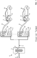
- FIG. 1 shows a charging arrangement 1 as it is known from the prior art.
- a medium-voltage network 2 and a medium-voltage transformer 3, which is connected to the medium-voltage network 2 on its primary side 4 and provides a TN low-voltage network 6 on its secondary side 5, are designed for this purpose.
- Several individual and separate charging stations 7 are then connected to this low-voltage network 6, the charging stations 7 in turn being coupled to a respective electric vehicle 10 via a respective charging cable 8 and a charging plug 9.
- the electric vehicle 10 has a traction battery 11, which is charged accordingly.
- the electric vehicle 10 also has an onboard charging management 12, which communicates with the charging column 7 and, for example, selects between an AC charging process and a DC charging process.
- a converter 13, here in the form of an active front end is provided in the charging station, as well as a potential separation 14 and a compensating plate 15 as a DC / DC converter.
- 7 electrical components are to be accommodated in the charging station.
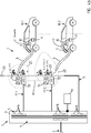
- FIG Figure 2 shows a charging arrangement 1 according to the invention.
- a medium-voltage transformer is also connected directly to a medium-voltage network 2 on the primary side 4.
- the difference according to the invention can be seen in comparison with FIG Figure 1 .
- Secondary windings 16 are directly present, which then form an IT low-voltage network 17 or supply it with voltage.
- a converter 13 in the form of an active front end and a compensating plate 15 in the form of a DC / DC converter are also provided.
- the charging cable 8 is connected directly to the IT low-voltage network 17 in order to carry out the charging process.
- the charging column itself or the charging station 7 is formed by the medium-voltage transformer 3 itself or the medium-voltage transformer 3 is integrated directly into the charging station 7.
- There are further secondary windings 16 are provided, which at the same time a TN low-voltage network 6 on the secondary side 5. This is formed here directly on the secondary side 5 of the medium-voltage transformer 3.
- the TN low-voltage network 6 can be coupled directly to the charging cable 8 in order to carry out an AC charging process.
- a contactor or switch for separating AC and DC charging processes is not shown for reasons of simplicity.
- the onboard charging management 12 can then select the corresponding charging process via the charging plug 9 and an existing communication module 20.
- the communication module 20 can be arranged in the area of the charging cable, but also in the charging plug.
- FIG. 3 An alternative design variant is shown in Figure 3 shown.
- an IT low-voltage network 17 is formed directly on the medium-voltage transformer 3 on the secondary side 5.
- a low-voltage transformer 18 is also provided, which then forms the TN low-voltage network 6.
- the subsequent structure in the direction of the electric vehicle 10 is analogous to FIG Figure 2 educated.
- Figure 4a shows a cost-effective expansion option according to the invention of the charging arrangement 1.
- two IT low-voltage networks 17.1 and 17.2 and theoretically arranged between 17.nn further IT low-voltage networks can be formed on the secondary side 5 of the medium-voltage transformer 3.
- Separate secondary windings 16 are assigned to each IT low-voltage network 17.
- a TN low-voltage network 6, which is also assigned its own secondary winding 16, is also formed.
- a charge management device 19 which regulates or controls the charging process of the multiple electric vehicles 101, 10.2 to be charged via the one medium-voltage transformer 3. More detailed explanations can also be found at Figure 6 .
- a third electric vehicle 10.3 is temporarily at least temporarily charged in parallel via the TN low-voltage network 6, that is to say as an AC charging process.
- An AC charging process would also be possible with the electric vehicles 10.1 and 10.2, as these are also connected to the TN low-voltage network 6 can be connected.
- the electric vehicles 10.1 and 10.2 are charged in the IT low-voltage network 17.1, 17.2 with a DC charging process.
- FIG. 4b shows an analog variant embodiment, with each IT low-voltage network 17.1, 17.n, 17.2 forming a charging point 21 here.
- a charging point 21 is then, for example, a charging station.
- Each charging point 21 has up to three charging plugs 9. These can be divided up in such a way that two charging plugs 9 are provided for DC charging in each charging point 21.
- a charging plug 9 can be designed for the DC-CCS standard and another charging plug 9 can be designed for the DC-CHAdeMO standard.
- a third charging plug 9 can be provided for AC charging.
- each charging point 21 can be formed at each charging point 21 via the connection to the medium-voltage transformer 3.
- the upper electric vehicle 10.1 in relation to the image plane is charged in the standard DC-CHAdeMO and the lower electric vehicle 10.2 is charged with an AC charging process.
- a charging point 21 can only have one DC charging plug, for example. This can optionally be designed according to the DC-CCS standard or according to the DC-CHAdeMO standard or another standard.
- Another charging point 21 of this charging station 7 can then have two or even three charging plugs 9. For example, two charging plugs 9 can be provided for DC charging, one for DC-CHAdeMO charging, and another for DC-CCS charging. A third charging plug 9 would then be provided for an AC charging process. Any number of further charging points 21 can be connected to the charging arrangement 1.
- Each charging point 21 can then have an individual number of charging plugs 9. In particular, it can be determined individually for each charging point 21 whether it should be provided for DC charging, AC charging or combined DC and AC charging or for the simultaneous provision of DC and AC charging processes.
- Figure 5 shows a similar structure to Figure 4 , with the difference that the TN low-voltage network 6 is implemented via a low-voltage transformer 18 in the IT low-voltage network 17.2.
- the charge management device 19 is then also connected to the low-voltage transformer 18.
- several electric vehicles 10.1, 10.2 can thus be charged simultaneously, each with AC or DC charging processes.
- AC charging processes all AC charging processes are supplied with voltage via the TN low-voltage network 6.
- a respective electric vehicle 10 is then supplied with voltage from an IT low-voltage network 17.
- the charging station 7 has to be able to provide the maximum charging power only once, or to provide a slightly, for example, twice, above the maximum required charging power for an electric vehicle 10.
- the maximum charging power of an electric vehicle should be 350 kW within the scope of the invention, and consequently the maximum charging power of the medium-voltage transformer less than 700 kW. It is thus possible to charge at least two, in particular several, electric vehicles 10 at the same time with the highest possible charging power required at the respective charging time of an electric vehicle 10, which however does not correspond to the maximum charging power at a given time. It thus arises despite in comparison to State of the art medium-voltage transformer 3 with smaller dimensions does not adversely affect the charging time.
- Each electric vehicle 10 can thus be charged in a time-efficient manner, that is to say with the shortest possible charging time and, at a given point in time, the greatest possible charging power required, depending on the time. It does not matter whether the electric vehicles are in AC and / or DC charging mode. Only the charging power is relevant.
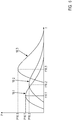
- the electric vehicle 10.1 has a maximum charging power P 10.1 at time t 10.1. Just like electric vehicles 10.2 and 10.3 do. The maximum required charging power of each electric vehicle 10 is different from one another. The electric vehicle 10.3 requires the greatest charging power P 10.3 in relation to the other electric vehicles 10.1, 10.2. There can be two reasons for this. On the one hand, the discharge status of the traction battery 11 of the electric vehicle 10.3 is different than that of the electric vehicles 10.2 and 10.3 and / or the traction battery 11 or the onboard charging management 12 of the electric vehicle 10.3 can process a greater charging power. From the schematic power-time diagram in Fig.
- the charging arrangement 1 can be designed in such a way that in each IT low-voltage network 17 and the TN low-voltage network 6, the maximum charging power required individually for the electric vehicle 10 is tapped at the secondary sides 5 of the medium-voltage transformer 3 at a time. If the currently required charging powers P10.1, P10.2, P10.3 of all electric vehicles 10.1, 10.2, 10.3 together exceed the maximum dimensioned power to be made available by the medium-voltage transformer 3 on the secondary side 5, the charge management device 19 intervene and reduce the required charging power and the available Split the standing charging power. For the charging process of each electric vehicle 10, however, such a temporary intervention can under certain circumstances be neglected or hardly noticeable.
- Several charging stations can be connected to a medium-voltage transformer 3, so that several electric vehicles 10 can be charged simultaneously with AC and / or DC charging.
- the charging power P of an electric vehicle 10 required for charging is not constant over the time t, but increases from the start of charging until the maximum required charging voltage is reached. This is also the point in time at which the corresponding charging station must provide the maximum charging power P for this electric vehicle. The charging power P then decays again, since the charging current is also reduced.
- two electric vehicles 10 are never connected at exactly the same point in time, a respective charging column is connected and / or the electric vehicles 10 connected in parallel have different charging states. The start of charging and / or the currently required charging power P is thus typically time-shifted.
- the designation vehicle 1 is selected for the first electric vehicle 10.1, the designation vehicle 2 for the second electric vehicle 10.2 and the designation vehicle 3 for the third electric vehicle 10.3.
- the respective charging process of each electric vehicle 10 begins at different times first electric vehicle 10 started with a maximum charging power P of 350kW. This then also corresponds to the currently required total output.
- a second electric vehicle 10 is connected and also charged with a maximum of 350 kW.
- the third electric vehicle 10 is operated with an AC charge at time t41 (maximum, for example, approximately 22 kW).
- the total line currently required on the secondary side 5 of the medium-voltage transformer 3 is shown in the curve with a solid line. In this example, it reaches a maximum of just under 460 kW.
- Fig. 8 it is also shown how the total power is divided if the third electric vehicle 10 is also to be charged with a 350 kW charge. Then between t41 and t46 the permissible total power of 500 kW, for example, would be exceeded. This is where the charge management device 19 comes into play: it determines the currently required total power of all charging processes. At time t41 it is determined that the charging power P must be limited. This is implemented in that the charging management device 19 intervenes and, for example, via the corresponding charging communication module 20, the available charging power P of the electric vehicle 10.3 is temporarily reduced and / or limited.
- the charging management device 19 By briefly reducing the maximum charging power P of the electric vehicle 10.3 by the charging management device 19, the total line at the medium-voltage transformer of 500 kW is not exceeded. The charging process of the third vehicle 10.3 is only extended to a limited extent.
- the medium-voltage transformer 3 can be operated briefly (several minutes up to 30 minutes) with an increased overload of, for example, a factor of 1.5.
- the temperature of the transformer windings and / or the temperature of the transformer core can be controlled.
- the charge management device 19 can thus achieve the maximum overall output by monitoring the temperature increase as needed. The increase preferably takes place by a maximum of a factor of 1.5.
- the total power of the medium-voltage transformer 3 on the secondary side 5 can be dimensioned to be less than or equal to the maximum charging power of an electric vehicle, for example less than or equal to () 350 kW.
- the charge management device 19 In order to determine the individually required maximum charging power P of an electric vehicle 10, the charge management device 19 must be provided with the information on the current charging power of the individual charges. This can be done by cable or wirelessly for each electric vehicle separately via the communication modules. Alternatively, the charging management device 19 can also measure the current charging power P with sensors. The temperatures of the medium-voltage transformer 3 (core and / or windings) are measured and also communicated to the charge management device 19. By means of these measurements, the charging management devices 19 can evaluate the respective current charging powers P and determine the respective maximum charging powers P for each electric vehicle and, if necessary, reduce them.
Landscapes
- Engineering & Computer Science (AREA)
- Power Engineering (AREA)
- Transportation (AREA)
- Mechanical Engineering (AREA)
- Charge And Discharge Circuits For Batteries Or The Like (AREA)
- Electric Propulsion And Braking For Vehicles (AREA)
Description
- Die vorliegende Erfindung betrifft eine Ladeanordnung für ein Elektrofahrzeug mit einer Traktionsbatterie, welche an einem Mittelspannungsnetz angeschlossen ist gemäß den Merkmalen von Anspruch 1 sowie ein Verfahren zum Betreiben der Ladeanordnung gemäß Anspruch 10, 11 und 12.
- Für das elektrische Fahren eines Elektro- oder Hybridfahrzeuges ist es notwendig, dass die Batterie, nachfolgend auch Traktionsbatterie genannt, des Elektrofahrzeuges über eine externe Energiequelle geladen wird. Dabei wird die Zuführung der Energie über ein Stecksystem mit einem Ladekabel realisiert, mit dem die externe Energiequelle mit dem Fahrzeug verbunden wird, so dass der Ladevorgang stattfinden kann.
- Damit ein Standard erreicht wird, wird der Ladevorgang in verschiedenen Normungen definiert. Dabei wird grundsätzlich zwischen einem AC-Ladevorgang und einem DC-Ladevorgang unterschieden. Bei einem AC-Ladevorgang wird das Elektrofahrzeug mit dem Ladekabel direkt an einer Steckdose angeschlossen, beispielsweise an einer Haushaltssteckdose, welche ein- oder dreiphasig ist. Die übertragbaren Leistungen sind hierbei auf etwa 22 kW begrenzt.
- Um höhere Ladeleistungen zu realisieren, wird die sogenannte DC-Ladetechnik verwendet. Bei dieser wird durch eine externe Ladestation eine DC-Spannung bereitgestellt, die über ein Ladekabel an das Fahrzeug und innerhalb des Fahrzeuges direkt an die Traktionsbatterie weitergegeben wird. Stand der Technik ist, dass damit Ladeleistungen von bis zu 350 kW erreicht werden.
- Hierzu werden Ladestationen bereitgestellt, die jetzt und in Zukunft - analog zu Tankstellen für Verbrennungskraftmaschinen - die Möglichkeit bereitstellen sollen, Elektrofahrzeuge zu laden. Solche Ladestationen können auch als Ladesäule bezeichnet werden.
- Stand der Technik ist es, dass Ladestationen an ein Niederspannungsnetz angeschlossen sind und hierüber mit einer Versorgungsspannung versorgt werden, welche wiederum gewandelt wird und als Ladespannung an das Kraftfahrzeug abgegeben wird. Die Niederspannungsnetze sind als TN-Netz bzw. TN-System ausgeführt. TN steht dabei für "terre neutre".
- Das Elektrofahrzeug wird dann je nach bordseitigem Lademanagement über die AC-Spannung oder über die DC-Spannung geladen. Beim DC-Ladevorgang schreibt die Norm IEC 61851-23 vor, dass zur Gewährleistung der elektrischen Sicherheit die DC-Spannung zum Fahrzeug als IT-Netz ausgeführt werden muss. IT steht dabei für "isolé terre". Aus diesem Grunde sind die Ladestationen mit einer Potentialtrennung ausgestattet, wobei diese typisch zwischen dem Umrichter und einem Ausgangssteller geschaltet wird. Die Potentialtrennung wird dabei gemäß dem Stand der Technik durch einen Resonanztransformator realisiert.
- Zusammengefasst bedeutet dies jedoch, dass die Ladestationen sowie die unmittelbar die Ladestationen umgebende Infrastruktur relativ komplex ausgebildet sind. Es müssen mehrere elektrische Bauteile von einer verteilten Spannung, die zumeist eine Mittelspannung ist, in der immobilen Ladeinfrastruktur vorgesehen werden, wobei zum einen die Investitionskosten zum Aufbau von Ladestationen, jedoch auch die Wartungs- und Unterhaltskosten einer solchen Ladestation hoch sind. Diese Kosten müssen letztendlich durch den Verbraucher durch einen erhöhten Kilowatt-Stunden-Preis getragen werden. Die elektrischen Bauteile müssen bei der Erstmontage gekauft werden sowie im Betrieb gewartet werden und bei Bedarf ausgetauscht werden. Zudem sind mitunter Betriebskosten hoch, da Kühlmaßnahmen für die elektrischen Bauteile durchgeführt werden müssen.
- Aus der
DE 10 2015 110 023 A1 ist eine Ladeanordnung bekannt, bei welcher eine Mittelspannung in eine Niederspannung umgewandelt wird und direkt für einen DC-Ladevorgang verwendet wird. - Aus der
DE 10 2011 084 362 A1 ist ein Onboard-Charger in einem Kraftfahrzeug bekannt, welche an ein TN-Ladesystem und auch an ein IT-Ladesystem angeschlossen werden kann. - Aus der
EP 2 930 813 A1 ist ein ortsfester Mittelspannungstransformator bekannt, an den örtlich getrennt, eine Niederspannungsladestation angeschlossen ist, wobei in die Leitung eine entsprechende Messtechnik eingegliedert ist. - Aufgabe der vorliegenden Erfindung ist es daher, eine Ladeanordnung mit wenig Bauteilen bereitzustellen, bei jedoch gleichzeitig gegenüber dem Stand der Technik gesteigerter Ladeleistung, die es ermöglicht, eine Ladeinfrastruktur für Elektrofahrzeuge aufzubauen.
- Die zuvor genannte Aufgabe wird mit einer Ladeanordnung mit den Merkmalen im Anspruch 1 gelöst.
- Ein verfahrenstechnischer Teil der Aufgabe wird mit den Merkmalen im Anspruch 10 sowie 11 und 12 gelöst.
- Vorteilhafte Weiterbildungen der erfindungsgemäßen Ladeanordnung sind in den abhängigen Ansprüchen aufgeführt.
- Die Ladeanordnung für ein Elektrofahrzeug mit einer Traktionsbatterie weist eine Ladestation auf, welche direkt angeschlossen ist an ein Mittelspannungsnetz. Ferner weist die Ladestation ein Ladekabel zur Koppelung mit dem Elektrofahrzeug auf. Die Ladeanordnung zeichnet sich nunmehr erfindungsgemäß dadurch aus, dass in der Ladestation ein Mittelspannungstransformator angeordnet ist, an welchem auf einer Primärseite die Mittelspannung anliegt und auf einer Sekundärseite unmittelbar mindestens ein IT-Niederspannungsnetz und ein davon elektrisch getrenntes TN-Niederspannungsnetz ausgebildet sind.
- Der erfindungswesentliche Vorteil besteht darin, dass sowohl AC- als auch DC-Ladevorgänge mit der erfindungsgemäßen Ladestation durchgeführt werden können. Gleichzeitig werden die benötigten Bauteile zum Aufbau der Ladestation gegenüber aus dem Stand der Technik bekannten Ladestationen reduziert. Dies begründet sich insbesondere darin, dass das IT-Niederspannungsnetz unmittelbar auf der Sekundärseite des Mittelspannungstransformators ausgebildet ist, wobei der Mittelspannungstransformator selbst auf der Primärseite unmittelbar an ein Mittelspannungsnetz angeschlossen ist. Weitere Leistungstransformatoren von der Sekundärseite des Mittelspannungstransformators bis zum Elektrofahrzeug können somit entfallen.
- Im Rahmen dieser Erfindung ist unter einem Elektrofahrzeug ein Elektrokraftfahrzeug, mithin ein Straßenfahrzeug, beispielsweise ein Personenkraftwagen oder Lastkraftwagen, zu verstehen. Ebenfalls können Flurförderfahrzeuge oder auch Spezialfahrzeuge verstanden werden. Unter einem Elektrofahrzeug können jedoch auch Luftfahrzeuge oder Wasserfahrzeuge verstanden werden. Diese können rein elektrisch betrieben sein oder auch als sogenanntes Hybridfahrzeug mit einem zusätzlichen Motor zur Erzeugung von elektrischer Energie, beispielsweise einer Verbrennungskraftmaschine, ausgestattet sein.
- Ein Mittelspannungsnetz ist ein in der Infrastruktur eines jeweiligen Landes, in der eine solche Ladeanordnung aufgestellt werden soll, vorhandene Versorgungsspannung. Diese beträgt üblicherweise mehr als 1.000 V und ist kleiner als 100 kV. Typischerweise liegt eine Mittelspannung zwischen 5 kV und 25 kV, insbesondere bei 10 kV, 12 kV oder auch 20 kV. Die Niederspannung eines Niederspannungsnetzes ist kleiner als 1.500 V und liegt typischerweise zwischen 200 V und 800 V, vorzugsweise von 400 V und 690 V.
- Das Mittelspannungsnetz, das TN-Niederspannungsnetz und das IT-Niederspannungsnetz sind bevorzugt in drei-phasig ausgebildet. Diese können jedoch auch ein-, zwei- oder mehr-phasig realisiert werden.
- Das IT-Niederspannungsnetz und das davon elektrisch getrennte TN-Niederspannungsnetz sind untereinander potentialgetrennt. Sie sind also elektrisch nicht miteinander verbunden. Im Sinne der Erfindung können auch weitere IT-Niederspannungsnetze durch mindestens eine zusätzliche Sekundärwicklung an dem Mittelspannungstransformator ausgebildet sein. Die IT-Niederspannungsnetze sind auf der Sekundärseite dann ebenfalls elektrisch voneinander getrennt ausgebildet, mithin potentialgetrennt ausgebildet.
- Die erfindungsgemäße Idee sieht nunmehr vor, dass für den DC-Ladevorgang kein zusätzlicher Transformator auf der Niederspannungsseite vorzusehen ist. Insbesondere entfällt in einer Ladesäule selber somit ein zusätzlicher Niederspannungstransformator. Der Mittelspannungstransformator wird direkt dazu genutzt, sowohl ein IT-Niederspannungsnetz als auch ein TN-Niederspannungsnetz bereitzustellen.
- Das TN-Niederspannungsnetz kann dabei im Rahmen der Erfindung durch mindestens eine zusätzliche Sekundärwicklung direkt von dem Mittelspannungstransformator bereitgestellt werden. Das TN-Niederspannungsnetz wird dann direkt von dem Mittelspannungstransformator aus der Mittelspannung transformiert. Das TN-Niederspannungsnetz kann jedoch auch durch einen Niederspannungstransformator ausgebildet sein, wobei der Niederspannungstransformator dann in einem Sekundärkreis auf der Sekundärseite des Mittelspannungstransformators angeordnet ist. Erfindungswesentlich ist jedoch, dass direkt die Niederspannung des IT-Niederspannungsnetzes durch den Mittelspannungstransformator bereitgestellt wird.
- An einem jeweiligen IT-Niederspannungsnetz ist zusätzlich dann ein Umrichter und/oder ein Ausgangssteller bzw. Ausgleichsteller vorgesehen. Der Umrichter ist beispielsweise ein "active front end" (AFE), ein "power factor correction" (PFC) oder ein Diodengleichrichter. Der Ausgleichssteller ist insbesondere ein DC/DC-Wandler.
- Das IT-Niederspannungsnetz wird für einen DC-Ladevorgang verwendet. Das TN-Niederspannungsnetz wird für AC-Ladevorgänge verwendet. Heutige Elektrofahrzeug werden zumeist mit AC-Ladestandard ausgestattet. Viele Fahrzeuge weisen jedoch auch schon die kombinierte Möglichkeit auf, auch DC-Ladevorgänge durchzuführen. Aufgrund der höheren zu übertragenden Ladeleistung ist in Zukunft damit zu rechnen, dass ein größerer Teil von Elektrofahrzeugen DC-ladefähig ist.
- Ein weiterer Vorteil ist, dass das TN-Niederspannungsnetz direkt zur AC-Ladung verwendet werden kann und dem Elektrofahrzeug über das Ladekabel unmittelbar zugeführt wird.
- Ferner ist dann noch ein Schütz oder Schalter vorgesehen, welcher beispielsweise in einem Ladestecker integriert sein kann oder auf Seiten der Ladestation vorgesehen ist. Soll nunmehr eine elektrische Tankstelle aufgebaut werden, welche eine Vielzahl von Ladestationen aufweist, so eignet sich die erfindungsgemäße Ladeanordnung hierfür insbesondere. Es können somit durch die erfindungsgemäße Ladestation mit dem Mittelspannungstransformator beispielsweise gleichzeitig zwei, drei, vier oder mehr IT-Niederspannungsnetze ausgebildet sein. Dies wird realisiert durch mindestens eine, dem jeweiligen IT-Niederspannungsnetz zugehörige Wicklungsanordnung auf der Sekundärseite des Mittelspannungstransformators. Ferner ist gleichzeitig immer ein TN-Niederspannungsnetz ausgebildet. Somit kann das TN-Niederspannungsnetz zum gleichzeitigen AC-Laden von mehreren Elektrofahrzeugen genutzt werden. Ein jedes IT-Niederspannungsnetz wird zum Laden eines Elektrofahrzeuges genutzt. Es können mehrere Elektrofahrzeuge gleichzeitig an dem Mittelspannungstransformator geladen werden. Die vorliegende Erfindung betrifft somit auch die Verwendung einer Ladeanordnung zum Laden von mindestens einem Elektrofahrzeug bzw. mehreren Elektrofahrzeugen sowie ein Verfahren zum Betreiben der Ladeanordnung.
- Hierzu ist ferner eine Lademanagementeinrichtung vorgesehen, wobei die Lademanagementeinrichtung dem Mittelspannungstransformator zugeordnet ist. Die Lademanagementeinrichtung gibt dabei für alle Niederspannungsnetze die maximal zulässige Leistung vor. Die Lademanagementeinrichtung gibt diese Werte dem jeweiligen Ladekommunikationsmodul, nachfolgend auch Kommunikationsmodul genannt, eines Elektrofahrzeuges und/oder eines Ladesteckers weiter, welches wiederum diese Information im Ladevorgang berücksichtigt. Beispielsweise kann in einem Ladestecker an einem jeden Ladekabel ein Kommunikationsmodul vorgesehen sein. Auf der Primärseite liegt somit die Mittelspannung an dem Mittelspannungstransformator an. Über das Kommunikationsmodul wird dann der jeweilige Energiebedarf für ein Elektrofahrzeug erfasst und über die Lademanagementeinrichtung derart geregelt oder gesteuert, dass dann eine Energieentnahme auf der Sekundärseite des Mittelspannungstransformators geregelt oder gesteuert wird für ein jeweiliges Niederspannungsnetz, insbesondere IT-Niederspannungsnetz.
- Eine vorteilhafte Weiterbildung der Erfindung sieht ferner vor, dass in dem Ladekabel, insbesondere in dem Ladestecker eines Ladekabels, ein Spannungskonverter angeordnet ist. Dabei wird eine Spannung größer 900 V, insbesondere größer 1.000 V durch das Ladekabel übertragen und dann durch den Spannungskonverter in dem Ladestecker auf eine kleinere Ladespannung für das Elektrofahrzeug konvertiert. Dies bietet insbesondere den Vorteil, dass bei gleicher oder höherer Ladeleistung ein geringerer Durchmesser des Ladekabels ermöglicht wird. Hierdurch lassen sich sowohl die Kosten zur Herstellung des Ladekabels senken, da diese zumeist aus Kupfer bestehen und Kupfer als Edelmetall einen hohen Einkaufspreis mit sich bringt. Zum anderen wird das Handling eines Ladekabels verbessert, da das mit dem Ladekabel einhergehende, nicht unerhebliche Eigengewicht gesenkt werden kann, so dass ein jeweiliger Fahrer eines Elektrofahrzeuges vereinfacht die Koppelung des Ladesteckers zur Durchführung des Ladevorganges vornehmen kann.
- Gleichzeitig kann der Spannungskonverter auch als Regel- bzw. Steuerungseinrichtung dienen, um den Ladevorgang mit dem Elektrofahrzeug durchzuführen. Somit kann zusätzliche Steuerungs- oder Regelungstechnik in der Ladestation entfallen, die ansonsten notwendig wäre, um zum einen mit dem Elektrofahrzeug zu kommunizieren, zum anderen um den Ladevorgang zu regeln bzw. zu steuern. Das Elektrofahrzeug kommuniziert somit mit dem Spannungskonverter in dem Ladestecker. Dieser greift dann die benötigte Spannung auf der Sekundärseite des Mittelspannungstransformators ab, leitet sie durch das Ladekabel und gibt sie dann an das Elektrofahrzeug konvertiert ab. Es ist somit möglich, die Leitungsquerschnitte der elektrischen Leiter in dem Ladekabel zu reduzieren bei mindestens gleichbleibender und/oder erhöhter, am Ladestecker zu Verfügung stehender Ladeleistung.
- Im Rahmen der Erfindung ist es somit möglich, über das Ladekabel Spannungen von mehr als 900 V, insbesondere mehr als 1.000 V, bevorzugt mehr als 1.200 V zu übertragen. Eine realistische Obergrenze zur maximal zu übertragenden Spannung sollte jedoch bei maximal 10.000 V, bevorzugt bei 5.000 V liegen. Im Rahmen der Erfindung hat es sich als vorteilig erwiesen, wenn Spannungen von 1.000 V bis 1.500 V übertragen werden. In diesem Falle weist das IT-Niederspannungsnetz eine solche Spannung auf. Die eigentliche Ladespannung kann dann auf einen Bereich um 400 V bis 850 V konvertiert werden, insbesondere auf 400 V oder 800 V. Das Verhältnis von Ladespannung zu über das Ladekabel übertragener Spannung beträgt bevorzugt kleiner 0,9. Dies bedeutet, dass die Ladespannung kleiner 0,9 mal der über das Ladekabel übertragenen Spannung ist, insbesondere kleiner 0,85, besonders bevorzugt kleiner 0,8, insbesondere kleiner 0,75. Das Verhältnis sollte jedoch größer 0,1 sein.
- Das in dem Ladestecker vorgesehene Kommunikationsmodul kann zum einen mit der Lademanagementeinrichtung der Ladestation kommunizieren. Es kann optional ergänzend auch mit dem Elektrofahrzeug, und hier mit dem Onboard-Lademanagementsystem des Elektrofahrzeuges, kommunizieren. Die Kommunikation kann kabelgebunden, jedoch auch drahtlos, beispielsweise über Bluetooth oder WLAN, erfolgen.
- Die vorliegende Erfindung betrifft weiterhin ein Verfahren zum Betreiben der Ladeanordnung, wobei mindestens n-Elektrofahrzeuge gleichzeitig in verschiedenen IT-Niederspannungsnetzen auf der Sekundärseite des Mittelspannungstransformators geladen werden, n ist dabei größer gleich (≥) 2. Optional wird ein weiteres Elektrofahrzeug im TN-Niederspannungsnetz geladen. Die maximal zur Verfügung stehende Ladeleistung auf der Sekundärseite des Mittelspannungstransformators ist kleiner als die benötigte maximale Ladeleistung der n-Elektrofahrzeuge zusammen addiert. Insbesondere ist die maximale auf der Sekundärseite zur Verfügung stehende Ladeleistung kleiner als die 1,5fache maximal benötigte Ladeleistung eines Elektrofahrzeuges. Bevorzugt entspricht die Ladeleistung auf der Sekundärseite des Mittelspannungstransformators gleich der maximal benötigten Ladeleistung eines Elektrofahrzeuges. Damit nunmehr alle angeschlossenen Elektrofahrzeuge bestmöglich geladen werden können, greift eine Lademanagementeinrichtung ein, wenn die zu einem Zeitpunkt benötigte Ladeleistung, die alle Elektrofahrzeuge dann abrufen, größer ist als die zur Verfügung stehende Ladeleistung auf der Sekundärseite, indem für ein oder mehrere Elektrofahrzeuge die jeweils dem Elektrofahrzeug zur Verfügung gestellte Ladeleistung temporär reduziert wird.
- Dies bringt erfindungsgemäß den Vorteil, dass jedes Elektrofahrzeug bestmöglich geladen werden kann, gleichzeitig jedoch die Dimensionierung des Mittelspannungstransformators im Verhältnis dazu recht klein ausfallen kann. Die anfallenden Kosten bei der Einrichtung der erfindungsgemäßen Ladeanordnung sowie auch beim Betreiben der Ladeanordnung können somit reduziert werden.
- Ein weiteres erfindungsgemäß vorteilhaftes Verfahren sieht vor, dass beim Betreiben der eingangs beschriebenen Ladeanordnung die maximal verfügbare Ladeleistung auf der Sekundärseite des Mittelspannungstransformators temporär um bis das 1,5fache überschritten wird. Insbesondere werden hierzu Niederfrequenztransformatoren verwendet, die in einem Hertzbereich kleiner 100 Hertz, besonders bevorzugt bei 50 oder 60 Hertz, arbeiten. Eine Überschreitung um bis das 1,5fache, der auf der Sekundärseite maximal zur Verfügung stehenden Ladeleistung, ist für einen Zeitbereich kleiner 10 Minuten, insbesondere kleiner 5 Minuten, unkritisch und bedarf insbesondere keiner gesteigerten Kühlmaßnahmen oder ähnlichem. Somit kann ebenfalls ein kleiner dimensionierter Mittelspannungstransformator genutzt werden, um gleichzeitig mehrere Fahrzeuge mit der größtmöglichen für jedes Fahrzeug zur Verfügung zu stellenden Ladeleistung geladen werden.
- Insbesondere ist es jedoch mit der eingangs beschriebenen Ladeanordnung möglich, dass sowohl in dem IT-Niederspannungsnetz ein Elektrofahrzeug mit einem DC-Ladevorgang geladen wird und zumindest temporär gleichzeitig in dem TN-Niederspannungsnetz ein weiteres Elektrofahrzeug mit einem AC-Ladevorgang geladen wird.
- Ein besonderer Vorteil ist neben dem oben genannten Verfahren zum Betreiben weiterhin, dass der Mittelspannungstransformator zu einem günstigeren Strompreis vom Energieanbieter betrieben werden kann, da die kWh im Mittelspannungsnetz günstiger ist als eine kWh, die in einem Niederspannungsnetz vom Energielieferanten bezogen wird.
- Weitere Vorteile, Merkmale, Eigenschaften und Aspekte der vorliegenden Erfindung sind Gegenstand der nachfolgenden Beschreibung. Bevorzugte Ausgestaltungsvarianten werden in den schematischen Figuren dargestellt. Diese dienen dem einfachen Verständnis der Erfindung. Es zeigen:
- Figur 1
- eine Ladeanordnung gemäß dem Stand der Technik,
- Figur 2
- eine erfindungsgemäße Ladeanordnung mit einem IT-Nieder-spannungsnetz und einem TN-Niederspannungsnetz,
- Figur 3
- eine Ausgestaltungsvariante der vorliegenden Erfindung mit zusätzlichem Niederspannungstransformator zur Ausbildung des TN-Niederspannungsnetzes,
- Figur 4a und b
- je eine Ausgestaltungsvariante der erfindungsgemäßen Ladean-ordnung mit 2 bis n IT-Niederspannungsnetzen sowie einem TN-Niederspannungsnetz,
- Figur 5
- eine Ausgestaltungsvariante analog zur
Figur 4 , jedoch mit zusätzlichem Niederspannungstransformator, - Figur 6
- ein Leistungs-Zeit-Diagramm zum Betreiben einer erfindungsgemäßen Ladeanordnung bei mehreren Fahrzeugen
- Fig. 7 bis 9
- verschiedene Leistungs-/Zeitdiagramme beim Betreiben einer Ladeanordnung.
- In den Zeichnungen werden für gleiche oder ähnliche Bauteile dieselben Bezugszeichen verwendet, auch wenn eine wiederholte Beschreibung aus Vereinfachungsgründen entfällt.
-
Figur 1 zeigt eine Ladeanordnung 1, wie sie aus dem Stand der Technik bekannt ist. Hierzu ist ein Mittelspannungnetz 2 ausgebildet sowie ein Mittelspannungstransformator 3, der auf seiner Primärseite 4 an das Mittelspannungsnetz 2 angeschlossen ist und auf seiner Sekundärseite 5 ein TN-Niederspannungsnetz 6 bereitstellt. An dieses Niederspannungsnetz 6 sind dann mehrere einzelne und jeweils separate Ladestationen 7 angeschlossen, wobei die Ladestationen 7 wiederum über ein jeweiliges Ladekabel 8 und einen Ladestecker 9 mit einem jeweiligen Elektrofahrzeug 10 gekoppelt sind. Das Elektrofahrzeug 10 weist eine Traktionsbatterie 11 auf, die entsprechend geladen wird. Das Elektrofahrzeug 10 weist ferner ein Onboard-Lademanagement 12 auf, welches mit der Ladesäule 7 kommuniziert und beispielsweise zwischen einem AC-Ladevorgang und einem DC-Ladevorgang auswählt. Ferner ist ein Umrichter 13, hier in Form eines activ front ends, in der Ladesäule vorgesehen sowie eine Potentialtrennung 14 und ein Ausgleichssteller 15 als DC/DC-Wandler. Somit sind in der Ladesäule 7 elektrische Bauteile unterzubringen. -
Figur 2 zeigt eine erfindungsgemäße Ladeanordnung 1. Hierbei ist ein Mittelspannungstransformator ebenfalls unmittelbar an ein Mittelspannungsnetz 2 auf der Primärseite 4 angeschlossen. Auf der Sekundärseite 5 des Mittelspannungstransformators 3 zeigt sich jedoch der erfindungsgemäße Unterschied im Vergleich zuFigur 1 . Es sind unmittelbar Sekundärwicklungen 16 vorhanden, welche dann ein IT-Niederspannungsnetz 17 ausbilden bzw. mit Spannung versorgen. In diesem IT-Niederspannungsnetz 17 sind dann noch ein Umrichter 13 in Form eines activ front ends sowie ein Ausgleichssteller 15 in Form eines DC/DC-Wandlers vorgesehen. Sodann ist jedoch das Ladekabel 8 zur Durchführung des Ladevorganges direkt an das IT-Niederspannungsnetz 17 angeschlossen. Komplexe, insbesondere bauraumtechnische große Ladesäulen können somit entfallen. Die Ladesäule selber bzw. die Ladestation 7 wird durch den Mittelspannungstransformator 3 selbst ausgebildet bzw. ist der Mittelspannungstransformator 3 in die Ladestation 7 direkt integriert. Es sind weitere Sekundärwicklungen 16 vorgesehen, die gleichzeitig ein TN-Niederspannungsnetz 6 auf der Sekundärseite 5 ausbilden. Dieses ist hier unmittelbar auf der Sekundärseite 5 des Mittelspannungstransformators 3 ausgebildet. Das TN-Niederspannungsnetz 6 kann zur Durchführung eines AC-Ladevorganges unmittelbar mit dem Ladekabel 8 gekoppelt sein. Ein Schütz bzw. Schalter zur Trennung von AC- und DC-Ladevorgängen ist aus Vereinfachungsgründen nicht eingezeichnet. Das Onboard-Lademanagement 12 kann dann über den Ladestecker 9 und ein vorhandenes Kommunikationsmodul 20 den entsprechenden Ladevorgang wählen. Das Kommunikationsmodul 20 kann dabei im Bereich des Ladekabels, jedoch auch im Ladestecker angeordnet sein. - Eine alternative Ausgestaltungsvariante ist in
Figur 3 dargestellt. Hier ist ebenfalls unmittelbar an dem Mittelspannungstransformator 3 auf der Sekundärseite 5 ein IT-Niederspannungsnetz 17 ausgebildet. Es ist jedoch weiterhin ein Niederspannungstransformator 18 vorgesehen, der dann das TN-Niederspannungsnetz 6 ausbildet. Der darauf folgende Aufbau in Richtung zu dem Elektrofahrzeug 10 ist analog zurFigur 2 ausgebildet. -
Figur 4a zeigt eine erfindungsgemäße kostengünstige Erweiterungsmöglichkeit der Ladeanordnung 1. Hier können zwei IT-Niederspannungsnetze 17.1 und 17.2 sowie theoretisch dazwischen angeordnet 17.n n weitere IT-Niederspannungsnetze auf der Sekundärseite 5 des Mittelspannungstransformators 3 ausgebildet sein. Jedem IT-Niederspannungsnetz 17 sind eigene Sekundärwicklungen 16 zugeordnet. Ebenfalls ausgebildet ist ein TN-Niederspannungsnetz 6, welchem ebenfalls eine eigene Sekundärwicklung 16 zugeordnet ist. - Zusätzlich ist eine Lademanagementeinrichtung 19 vorgesehen, welche den Ladevorgang der mehreren über den einen Mittelspannungstransformator 3 zu ladenden Elektrofahrzeuge 101, 10.2 regelt bzw. steuert. Nähere Erläuterungen dazu finden sich ebenfalls zu
Figur 6 . - Auch dargestellt in
Figur 4a ist, dass ein drittes Elektrofahrzeug 10.3 zeitlich zumindest temporär parallel über das TN-Niederspannungsnetz 6 geladen wird, also als AC-Ladevorgang. Ein AC-Ladevorgang wäre auch bei den Elektrofahrzeugen 10.1 und 10.2 möglich, da diese auch an das TN-Niederspannungsnetz 6 angeschlossen werden können. Die Elektrofahrzeuge 10.1 und 10.2 werden jedoch, wie oben beschrieben ist, im IT Niederspannungsnetz 17.1, 17.2 mit einem DC-Ladevorgang geladen. -
Figur 4b zeigt eine analoge Ausführungsvariante, wobei hier jedes IT Niederspannungsnetz 17.1, 17.n, 17.2 einen Ladepunkt 21 ausbildet. Ein Ladepunkt 21 ist beispielsweise dann eine Ladesäule. Jeder Ladepunkt 21 weist bis zu drei Ladestecker 9 auf. Diese können derart aufgeteilt sein, dass in je einem Ladepunkt 21 zwei Ladestecker 9 für das DC-Laden vorgesehen sind. Ein Ladestecker 9 kann den Standard DC-CCS und ein weiterer Ladestecker 9 kann für den DC-CHAdeMO Standard ausgebildet sein. Ein dritter Ladestecker 9 kann für das AC-Laden vorgesehen sein. - Somit können an jedem Ladepunkt 21 über den Anschluss an den Mittelspannungstransformator 3 bis zu drei Ladestecker 9 ausgebildet sein. Damit ist es möglich, verschiedene Ladestandards an einem Ladepunkt 21, mithin einer Ladesäule zur Verfügung zu stellen. Beispielsweise wird das auf die Bildebene bezogen obere Elektrofahrzeug 10.1 in dem Standard DC-CHAdeMO geladen und das untere Elektrofahrzeug 10.2 mit einem AC-Ladevorgang geladen.
- Es ist im Rahmen der Erfindung jedoch auch möglich, die einzelnen Ladepunkte 21 untereinander unterschiedlich auszustatten. Dies kann bedeuten, ein Ladepunkt 21 kann beispielsweise nur einen DC-Ladestecker aufweisen. Dieser kann wahlweise nach dem DC-CCS Standard oder nach dem DC-CHAdeMO Standard oder auch einem weiteren Standard ausgebildet sein. Ein weiterer Ladepunkt 21 dieser Ladestation 7 kann dann zwei oder auch drei Ladestecker 9 aufweisen. Beispielsweise können zwei Ladestecker 9 für das DC-Laden vorgesehen sein, einer für das DC-CHAdeMO Laden, ein weiterer für das DC-CCS Laden. Ein dritter Ladestecker 9 wäre dann für einen AC-Ladevorgang vorgesehen. Es können beliebig viele weitere Ladepunkte 21 an die Ladeanordnung 1 angeschlossen werden. Ein jeder Ladepunkt 21 kann dann eine individuelle Anzahl an Ladesteckern 9 aufweisen. Insbesondere kann für jeden Ladepunkt 21 individuell festgelegt werden, ob dieser für DC-Laden, AC-Laden oder kombiniertes DC- und AC-Laden oder zur gleichzeitigen Bereitstellung von DC- und AC-Ladevorgängen vorgesehen sein soll.
-
Figur 5 zeigt einen ähnlichen Aufbau zuFigur 4 , mit dem Unterschied, dass das TN-Niederspannungsnetz 6 über einen Niederspannungstransformator 18 in dem IT-Niederspannungsnetz 17.2 realisiert wird. Die Lademanagementeinrichtung 19 ist dann ebenfalls mit dem Niederspannungstransformator 18 verbunden. GemäßFiguren 4 und5 können somit mehrere Elektrofahrzeuge 10.1, 10.2 gleichzeitig mit jeweils AC- oder DC-Ladevorgängen geladen werden. Im Falle von AC-Ladevorgängen werden alle AC-Ladevorgänge über das TN-Niederspannungsnetz 6 mit Spannung versorgt. Im Falle eines DC-Ladevorganges wird dann ein jeweiliges Elektrofahrzeug 10 aus jeweils einem IT-Niederspannungsnetz 17 mit Spannung versorgt. - Die für den Ladevorgang notwendige Ladeleistung ist nicht über die Zeit hinweg konstant. Sie steigt ab dem Start des Ladevorganges zunächst an, bis die maximale Ladespannung erreicht wird. Danach nimmt die Ladeleistung wiederum ab. Dies bedeutet, zu dem Zeitpunkt, an dem die maximale Ladeleistung zur Verfügung gestellt werden muss, muss auch die Ladestation 7 diesem einen Elektrofahrzeug 10 die maximale Ladeleistung zur Verfügung stellen. Im Praxisbetrieb werden jedoch nicht zwei oder mehr Fahrzeuge exakt gleichzeitig mit dem gleichen Entladezustand der Traktionsbatterie 11 an die Ladestation 7 angeschlossen, sondern zeitlich versetzt. Soll jedem Elektrofahrzeug 10 die maximale Ladeleistung zur Verfügung gestellt werden, bedeutet dies nicht, dass die Ladestation 7 dazu ausgelegt werden muss, n (n = Anzahl der angeschlossenen Elektrofahrzeuge) mal die maximale Ladeleistung zur Verfügung stellen zu können. Im Prinzip muss die Ladestation 7 nur einmal die maximale Ladeleistung zur Verfügung stellen können, bzw. eine geringfügig, beispielsweise bei 2mal über der maximal benötigten Ladeleistung für ein Elektrofahrzeug 10 zur Verfügung stellen. Dies bestimmt die Auslegung der Leistungsfähigkeit des Mittelspannungstransformators 3. Die maximale Ladeleistung eines Elektrofahrzeuges sollte im Rahmen der Erfindung bei 350 kW liegen, mithin die maximale Ladeleistung des Mittelspannungstransformators bei kleiner 700 kW. Es ist somit möglich, mindestens zwei, insbesondere mehrere Elektrofahrzeug 10 zeitgleich zu laden mit der zum jeweiligen Ladezeitpunkt eines Elektrofahrzeuges 10 benötigten größtmöglichen Ladeleistung, welche jedoch nicht der zu einem Zeitpunkt jeweils maximalen Ladeleistung entspricht. Es entsteht somit trotz im Vergleich zum Stand der Technik geringer dimensioniertem Mittelspannungstransformator 3 keine negative Beeinträchtigung der Ladedauer. Jedes Elektrofahrzeug 10 kann somit zeiteffektiv, mithin mit kürzestmöglicher Ladezeit und zu einem jeweiligen Zeitpunkt zeitabhängig größtmöglicher benötigter Ladeleistung geladen werden. Dabei spielt es keine Rolle, ob sich die Elektrofahrzeuge im AC- und/oder DC-Ladebetrieb befinden. Es sind lediglich die Ladeleistungen relevant.
- Dieser Ladevorgang wird beispielhaft in
Figur 6 dargestellt. Das Elektrofahrzeug 10.1 weist eine maximale Ladeleistung P 10.1 zum Zeitpunkt t 10.1 auf. Genauso, wie es die Elektrofahrzeuge 10.2 und 10.3 tun. Die jeweils maximal benötigte Ladeleistung eines jeden Elektrofahrzeuges 10 ist voneinander verschieden. Das Elektrofahrzeug 10.3 benötigt die größte Ladeleistung P 10.3 in Relation zu den anderen Elektrofahrzeugen 10.1, 10.2. Dies kann zweierlei Gründe haben. Zum einen ist der Entladezustand der Traktionsbatterie 11 des Elektrofahrzeugs 10.3 anders als bei den Elektrofahrzeugen 10.2 und 10.3 und/oder die Traktionsbatterie 11 bzw. das Onboard-Lademanagement 12 des Elektrofahrzeugs 10.3 können eine größere Ladeleistung verarbeiten. Aus dem schematischen Leistungs-Zeit-Diagramm inFig. 6 wird deutlich, dass nicht zu einem Zeitpunkt ein n-facher Wert der jeweils maximalen Ladeleistung P10.1, P10.2, P10.3 benötigt wird, sondern die jeweils maximale Ladeleistung zeitlich versetzt benötigt wird. Somit ist es selbst beim zeitlich überschnittenen Laden von drei Elektrofahrzeugen 10.1, 10.2, 10.3 ausreichend, über die Ladestation 7 eine maximale Ladeleistung, die beispielsweise dem 1,5-fachen der maximalen Ladeleistung P10.3 des Elektrofahrzeuges 10.3 entspricht, bereitzustellen. - Die erfindungsgemäße Ladeanordnung 1 kann derart ausgelegt werden, dass in jedem IT-Niederspannungsnetz 17 und dem TN-Niederspannungsnetz 6 die individuell für das Elektrofahrzeug 10 benötigte maximale Ladeleistung zu einem Zeitpunkt an den Sekundärseiten 5 des Mittelspannungstransformators 3 abgegriffen wird. Sollten zu einem Zeitpunkt die aktuell benötigte Ladeleistungen P10.1, P10.2, P10.3 aller Elektrofahrzeuge 10.1, 10.2, 10.3 zusammen die maximal dimensionierte, durch den Mittelspannungstransformator 3 zur Verfügung zu stellende Leistung auf der Sekundärseite 5 überschreiten, kann die Lademanagementeinrichtung 19 eingreifen und die benötigten Ladeleistungen reduzieren und die zur Verfügung stehende Ladeleistung aufteilen. Für den Ladevorgang eines jeden Elektrofahrzeugs 10 ist ein solcher temporärer Eingriff unter Umständen jedoch zu vernachlässigen bzw. kaum spürbar.
- Gemäß der
Figuren 4 oder5 können mehrere Ladesäulen an einem Mittelspannungstransformator 3 angeschlossen sein, so dass mehrere Elektrofahrzeuge 10 gleichzeitig mit AC- und/oder DC Ladung geladen werden können. - Die bei der Ladung notwendige Ladeleistung P eines Elektrofahrzeuges 10 ist über die Zeit t hinweg nicht konstant, sondern steigt ab Ladestart zunächst an, bis die maximale benötigte Ladespannung erreicht wird. Dies ist auch der Zeitpunkt zu dem die entsprechende Ladesäule für dieses Elektrofahrzeug die maximale Ladeleistung P zur Verfügung stellen muss. Danach klingt die Ladeleistung P wieder ab, da auch der Ladestrom reduziert wird. In der Praxis werden zwei Elektrofahrzeuge 10 nie exakt zum gleichen Zeitpunkt angeschlossen eine jeweilige Ladesäule angeschlossen und/oder die parallel anschlossenen Elektrofahrzeuge 10 haben unterschiedliche Ladezustände. Somit ist der Ladestart und/oder die aktuell benötigte Ladeleistung P typischerweise zeitversetzt.
- In
Figur 7 ist nun exemplarisch eine Ladeanordnung 1 mit drei Elektrofahrzeugen 10 gezeigt. Es werden verschiedene strichpunktierte Linien dargestellt für die Elektrofahrzeuge (=Fahrzeug). Die durchgezogene Linie entspricht der jeweils benötigten Gesamtleistung. Für das erste Elektrofahrzeug 10.1 ist die Bezeichnung Fahrzeug 1 gewählt, für das zweite Elektrofahrzeug 10.2 die Bezeichnung Fahrzeug 2 und für das dritte Elektrofahrzeug 10.3 die Bezeichnung Fahrzeug 3. Es beginnt zu unterschiedlichen Zeitpunkten der jeweilige Ladevorgang eines jeden Elektrofahrzeuges 10. Zum Zeitpunkt t1 wird das erste Elektrofahrzeug 10 mit einer maximalen Ladeleistung P von 350kW begonnen. Dies entspricht dann auch der aktuell benötigten Gesamtleistung. Zu einem späteren Zeitpunkt t26 wird ein zweites Elektrofahrzeug 10 angeschlossen und ebenfalls mit maximal 350 kW geladen. Das dritte Elektrofahrzeug 10 wird zum Zeitpunkt t41 mit einer AC-Ladung betrieben (maximal bspw. etwa 22 kW). Die jeweils aktuell benötigte Gesamtleitung auf der Sekundärseite 5 des Mittelspannungstransformators 3 ist in der Kurve mit durchgezogener Linie dargestellt. Sie erreicht bei diesem Beispiel maximal knapp 460 kW. - Hier zeigt sich der Vorteil der Erfindung: Es können mehrere Ladungen mit jeweils maximaler benötigter Ladeleistung P eines Elektrofahrzeuges 10 von 350 kW an einer Ladeanordnung 1 durchgeführt werden, obwohl der Mittelspannungstransformator 3 mit einer geringeren maximalen Ladeleistung P auf der Sekundärseite 5 kleiner dem zweifachen der durch die Elektrofahrzeuge 10 benötigten maximalen Ladeleistung P betrieben werden. Der Mittelspannungstransformator 3 kann somit auf der Sekundärseite 5 eine maximale Ladelistung P von zum Beispiel 500kW aufweisen, anstatt 2*350kW = 700 kW, was die Herstellkosten reduziert. Wird dagegen die Ladeanordnung 1 gemäß
Fig. 1 nach Stand der Technik aufgebaut, muss jede Ladesäule und somit jeder Resonanzkonverter für je 350 kW ausgelegt werden, was entsprechend hohe Kosten darstellt. - In
Fig. 8 wird weiterhin gezeigt, wie die Gesamtleistung sich aufteilt, wenn das dritte Elektrofahrzeug 10 auch mit einer 350kW-Ladung geladen werden soll. Dann würde zwischen t41 und t46 die zulässige Gesamtleistung von beispielhaft 500kW überschritten. Hier kommt nun die Lademanagementeinrichtung 19 zum Einsatz: Diese ermittelt die jeweils aktuell benötigte Gesamtleistung aller Ladevorgänge. Zum Zeitpunkt t41 wird ermittelt, dass die Ladeleistung P begrenzt werden muss. Dies wird dadurch realisiert, dass die Lademanagementeinrichtung 19 eingreift und bspw. über das entsprechende Lade Kommunikationsmodul 20 die zur Verfügung stehende Ladeleistung P des Elektrofahrzeuges 10.3 temporär reduziert und/oder begrenzt. - Durch kurzzeitige Reduzierung der maximalen Ladeleistung P von Elektrofahrzeug 10.3 durch die Lademanagementeinrichtung 19 wird die Gesamtleitung am Mittelspannungstransformator von 500 kW nicht überschritten. Der Ladevorgang des dritten Fahrzeuges 10.3 wird aber nur bedingt verlängert.
- Ein weiterer Vorteil der Erfindung liegt darin, dass der Mittelspannungstransformator 3 kurzzeitig (mehrere Minuten bis zu 30 Minuten) bei einer erhöhten Überlast von beispielhaft dem Faktor 1,5 betrieben werden kann. Um die Überlast des Mittelspannungstransformators 3 zu überwachen, kann die Temperatur der Transformator-Wicklungen und/oder die Temperatur des Transformatorkernes kontrolliert werden. Die Lademanagementeinrichtung 19 kann somit durch die Überwachung der Temperatur die maximale Gesamtleistung bedarfsgerecht erhöhen. Die Erhöhung findet bevorzugt maximal um den Faktor 1,5 statt.
- Im Rahmen der Erfindung kann die Gesamtleistung des Mittelspannungstransformators 3 auf der Sekundärseite 5 auf kleiner gleich der maximalen Ladeleistung eines Elektrofahrzeuges, beispielsweise kleiner gleich (≤) 350 kW dimensioniert werden. Es können jedoch mehrere Elektrofahrzeuge 10 mit einer maximalen Ladeleistung P nach dem o.g. Schema gleichzeitig geladen werden. Die Lademanagementeinrichtung 19 muss zur Ermittlung der jeweils individuell benötigten maximalen Ladeleistung P eines Elektrofahrzeuges 10 die Informationen der aktuellen Ladeleistung der einzelnen Ladungen mitgeteilt bekommen. Dies kann über die Kommunikationsmodule kabelgebunden oder drahtlos für jedes Elektrofahrzeug separat erfolgen. Alternativ kann auch die Lademanagementeinrichtung 19 die aktuelle Ladeleistung P mit Sensoren messen. Die Temperaturen des Mittelspannungstransformators 3 (Kern und/oder Wicklungen) werden gemessen und ebenfalls der Lademanagementeinrichtung 19 mitgeteilt. Durch diese Messungen kann die Lademanagementeinrichtungen 19 die jeweils aktuellen Ladeleistungen P auswerten und die jeweils maximalen Ladeleistungen P für ein jedes Elektrofahrzeug festlegen und ggf. reduzieren.
-
- 1 -
- Ladeanordnung
- 2 -
- Mittelspannungsnetz
- 3 -
- Mittelspannungstransformator
- 4 -
- Primärseite zu 3
- 5 -
- Sekundärseite zu 3
- 6 -
- TN-Niederspannungsnetz
- 7 -
- Ladestation
- 8 -
- Ladekabel
- 9 -
- Ladestecker
- 10 -
- Elektrofahrzeug
- 10.1 -
- Erstes Elektrofahrzeug
- 10.2 -
- Zweites Elektrofahrzeug
- 10.3 -
- Drittes Elektrofahrzeug
- 11 -
- Traktionsbatterie
- 12 -
- Onboard-Lademanagement
- 13 -
- Umrichter
- 14 -
- Potentialtrennung
- 15 -
- Ausgleichssteller
- 16 -
- Sekundärwicklung
- 17 -
- IT-Niederspannungsnetz
- 18 -
- Niederspannungstransformator
- 19 -
- Lademanagementeinrichtung
- 20 -
- Ladekommunikationsmodul
- 21 -
- Ladepunkt
- P -
- Ladeleistung
- t -
- Zeit
Claims (12)
- Ladeanordnung (1) für ein Elektrofahrzeug (10) mit einer Traktionsbatterie (11), aufweisend eine Ladestation (7), direkt angeschlossen an ein Mittelspannungsnetz (2) und ein Ladekabel (8) zur Koppelung mit dem Elektrofahrzeug (10), wobei in der Ladestation (7) ein Mittelspannungstransformator (3) angeordnet ist, an welchem auf einer Primärseite (4) die Mittelspannung anliegt dadurch gekennzeichnet, dass auf einer Sekundärseite (5) mindestens ein IT Niederspannungsnetz (17) und ein davon elektrisch getrenntes TN Niederspannungsnetz (6) ausgebildet sind und dass eine Lademanagementeinrichtung (19) dem Mittelspannungstransformator (3) zugeordnet ist, wobei die Lademanagementeinrichtung (19) alle Niederspannungsnetze (6, 17) regelt oder steuert.
- Ladeanordnung (1) nach Anspruch 1, dadurch gekennzeichnet, dass das TN Niederspannungsnetz (6) durch mindestens eine zusätzliche Sekundärwicklung (16) direkt an dem Mittelspannungstransformator (3) ausgebildet ist oder dass das TN Niederspannungsnetz (6) durch einen Niederspannungstransformator (18) ausgebildet ist, wobei der Niederspannungstransformator (18) in einem Sekundärkreis auf der Sekundärseite (5) des Mittelspannungstransformators (3) angeordnet ist.
- Ladeanordnung (1) nach Anspruch 1 oder 2, dadurch gekennzeichnet, dass das TN-Niederspannungsnetz (6) für AC Ladevorgänge verwendet wird und/oder dass das IT-Niederspannungsnetz (17) für DC Ladevorgänge verwendet wird.
- Ladeanordnung (1) nach einem der Ansprüche 1 bis 3, dadurch gekennzeichnet, dass mindestens ein zweites IT Niederspannungsnetz (17) an dem Transformator ausgebildet ist, vorzugsweise über eine weitere Sekundärwicklung (16).
- Ladeanordnung (1) nach Anspruch 4, dadurch gekennzeichnet, dass die IT Niederspannungsnetze (17) auf der Sekundärseite (5) getrennt ausgebildet sind.
- Ladeanordnung (1) nach einem der Ansprüche 1 bis 5, dadurch gekennzeichnet, dass die maximale Ladeleistung des Mittelspannungstransformators (3) auf der Sekundärseite (5) kleiner gleich 700 kW ist, wobei die Ladeleistung eines jeden Ladevorganges für ein Elektrofahrzeug (10) von der Lademanagementeinrichtung (19) ermittelt wird und dieser Wert dem entsprechenden Ladekommunikationsmodul (20) mitgeteilt wird, und somit im Ladevorgang berücksichtigt wird.
- Ladeanordnung (1) nach einem der Ansprüche 1 bis 6, dadurch gekennzeichnet, dass in dem IT Niederspannungsnetz (17) ein Umrichter (13) und/oder ein Ausgleichssteller (15) vorgesehen sind.
- Ladeanordnung (1) nach einem der Ansprüche 1 bis 7, dadurch gekennzeichnet, dass in dem Ladekabel (8), insbesondere in dem Ladestecker (9), ein Spannungskonverter angeordnet ist, wobei bevorzugt eine Spannung größer 900V, insbesondere größer 1000V durch das Ladekabel (8) übertragen wird, die dann durch den Spannungskonverter in dem Ladestecker (9) auf eine kleinere Ladespannung konvertiert wird.
- Ladeanordnung (1) nach einem der Ansprüche 1 bis 8, dadurch gekennzeichnet, dass in einem Ladestecker (9) ein Kommunikationsmodul zur Kommunikation mit der Lademanagementeinrichtung (19) und/oder mit dem Elektrofahrzeug (10) vorgesehen ist.
- Verfahren zum Betreiben einer Ladeanordnung (1) mit den Merkmalen von mindestens Anspruch 1, dadurch gekennzeichnet, dass mindestens n-Elektrofahrzeuge (10) gleichzeitig in verschiedenen IT Niederspannungsnetzen (17) geladen werden, wobei n ≥ 2 (größer gleich) sowie optional mindestens ein weiteres Elektrofahrzeug im TN-Niederspannungsnetz (6) geladen wird, wobei die maximal zur Verfügung stehende Ladeleistung (P) auf der Sekundärseite (5) des Mittelspannungstransformators (17) kleiner als die benötigte maximale Ladeleistung (P) von den n Elektrofahrzeugen (10) ist, insbesondere kleiner als die 1,5 fache maximal benötigte Ladeleistung (P) eines Elektrofahrzeuges (10), bevorzugt ist die Ladeleistung (P) auf der Sekundärseite (5) des Mittelspannungstransformators (3) gleich der maximal benötigten Ladeleistung (P) eines Elektrofahrzeuges (10), wobei eine Lademanagementeinrichtung (19) eingreift, wenn die zu einem Zeitpunkt benötigte Ladeleistung (P) von zwei oder mehrere Elektrofahrzeugen (10) zusammen addiert größer ist, als die zur Verfügung stehende Ladeleistung (P), indem für ein oder mehrere Elektrofahrzeuge (10) die jeweils dem Elektrofahrzeug (10) zur Verfügung gestellte Ladeleistung (P) temporär reduziert wird.
- Verfahren zum Betreiben einer Ladeanordnung (1) mit den Merkmalen von mindestens Anspruch 1, dadurch gekennzeichnet, dass die maximal verfügbare Ladeleistung (P) auf der Sekundärseite (5) des Mittelspannungstransformators temporär um bis das 1,5fache überschritten wird.
- Verfahren zum Betreiben einer Ladeanordnung (1) mit den Merkmalen von mindestens Anspruch 1, dadurch gekennzeichnet, dass ein Elektrofahrzeug (10) in dem IT-Niederspannungsnetz (17) und ein weiteres Elektrofahrzeug in dem TN-Niederspannungsnetz (6) zumindest temporär gleichzeitig geladen werden.
Applications Claiming Priority (2)
| Application Number | Priority Date | Filing Date | Title |
|---|---|---|---|
| DE102017128573.3A DE102017128573B3 (de) | 2017-12-01 | 2017-12-01 | Ladeanordnung für ein Elektrofahrzeug an einem Mittelspannungsnetz sowie Verfahren zu deren Betreiben |
| PCT/DE2018/100974 WO2019105513A2 (de) | 2017-12-01 | 2018-11-30 | Ladeanordnung für ein elektrofahrzeug an einem mittelspannungsnetz sowie verfahren zu deren betreiben |
Publications (2)
| Publication Number | Publication Date |
|---|---|
| EP3717300A2 EP3717300A2 (de) | 2020-10-07 |
| EP3717300B1 true EP3717300B1 (de) | 2021-09-01 |
Family
ID=64734013
Family Applications (1)
| Application Number | Title | Priority Date | Filing Date |
|---|---|---|---|
| EP18821689.9A Active EP3717300B1 (de) | 2017-12-01 | 2018-11-30 | Ladeanordnung für ein elektrofahrzeug an einem mittelspannungsnetz sowie verfahren zu deren betreiben |
Country Status (5)
| Country | Link |
|---|---|
| US (1) | US11458859B2 (de) |
| EP (1) | EP3717300B1 (de) |
| CN (1) | CN111556822A (de) |
| DE (1) | DE102017128573B3 (de) |
| WO (1) | WO2019105513A2 (de) |
Families Citing this family (7)
| Publication number | Priority date | Publication date | Assignee | Title |
|---|---|---|---|---|
| DE102019204337A1 (de) * | 2019-03-28 | 2020-10-01 | Siemens Aktiengesellschaft | Ladesystem, Lastverteilungseinrichtung und Verfahren zum Laden von Fahrzeugbatterien |
| DE102019006065A1 (de) * | 2019-08-28 | 2021-03-04 | Kostal Automobil Elektrik Gmbh & Co. Kg | Ladesystem zum Gleichstromladen der Traktionsbatterie eines elektrisch angetriebenen Kraftfahrzeugs |
| DE102020200872A1 (de) * | 2020-01-24 | 2021-07-29 | Schmidhauser Ag | Stromrichter, Ladesäule und Fahrzeug |
| US20230271524A1 (en) * | 2020-06-19 | 2023-08-31 | Georgia Tech Research Corporation | Electric vehicle charging systems and methods |
| CN114905996B (zh) * | 2022-06-02 | 2023-02-28 | 广州弘信信息科技有限公司 | 有序充电的电动汽车分体式充电桩 |
| US20240223097A1 (en) * | 2022-12-23 | 2024-07-04 | Mcmaster University | Dual-active bridge converter and applications of same |
| US12068632B2 (en) * | 2023-01-17 | 2024-08-20 | Delta Electronics, Inc. | Charging system |
Family Cites Families (22)
| Publication number | Priority date | Publication date | Assignee | Title |
|---|---|---|---|---|
| JPH0965509A (ja) * | 1995-06-14 | 1997-03-07 | Toyota Autom Loom Works Ltd | 電気自動車用電池の充電方法及び電気自動車用充電器 |
| DE102010014417A1 (de) | 2010-04-08 | 2011-10-13 | Rolf Morich | Intelligentes Ladekabel für Elektrofahrzeuge |
| DE102011084362B4 (de) * | 2011-03-30 | 2015-03-05 | Bender Gmbh & Co. Kg | Elektrische Schutz- und Überwachungseinrichtung in einem Elektrofahrzeug zum sicheren Fahrbetrieb sowie zum sicheren Lade- und Rückspeisebetrieb des Elektrofahrzeugs an einer Ladestation |
| NL2008058C2 (en) * | 2011-12-29 | 2013-07-03 | Epyon B V | Method, system and charger for charging a battery of an electric vehicle. |
| US9120390B2 (en) * | 2012-03-08 | 2015-09-01 | General Electric Company | Apparatus for transferring energy using onboard power electronics and method of manufacturing same |
| DE102012207671A1 (de) * | 2012-05-09 | 2013-11-14 | Robert Bosch Gmbh | Batterie mit einer Mehrzahl von in Batteriesträngen angeordneten Batteriemodulen sowie Verfahren zum Betreiben der Batterie |
| DE102013211265A1 (de) * | 2013-06-17 | 2014-12-18 | Siemens Aktiengesellschaft | Energiemanagementvorrichtung und Verfahren zur Steuerung eines Ladevorgangs |
| DE102013219545A1 (de) * | 2013-09-27 | 2015-04-02 | Continental Automotive Gmbh | Verfahren, Fahrzeug und Anordnung |
| NO337360B1 (no) | 2014-03-11 | 2016-03-29 | Zaptec Ip As | Strømforsyningssystem for lading av elektriske kjøretøy |
| JP6011570B2 (ja) * | 2014-03-17 | 2016-10-19 | 株式会社デンソー | 車両用充放電システム |
| DE102014005089A1 (de) * | 2014-04-08 | 2015-10-08 | Rwe Deutschland Ag | Verfahren und Vorrichtung zur Erfassung einer elektrischen Größe eines elektrischen Verteilnetzes |
| CN105680706A (zh) | 2014-11-18 | 2016-06-15 | 台达电子工业股份有限公司 | 直流供电装置 |
| DE102015210884A1 (de) * | 2015-06-15 | 2016-12-15 | Siemens Aktiengesellschaft | Netzregelung bei Grenzwertüberschreitungen in einem Nieder- oder Mittelspannungsnetz |
| DE102015110023A1 (de) | 2015-06-23 | 2016-12-29 | Dr. Ing. H.C. F. Porsche Aktiengesellschaft | Ladestation und Verfahren zum Laden eines Plug-In-Kraftfahrzeuges an einer Ladesäule |
| US11479139B2 (en) * | 2015-09-11 | 2022-10-25 | Invertedpower Pty Ltd | Methods and systems for an integrated charging system for an electric vehicle |
| CN105480110B (zh) * | 2016-01-12 | 2019-02-19 | 沈阳工业大学 | 智能充电桩及智能充电方法 |
| WO2017201125A1 (en) * | 2016-05-18 | 2017-11-23 | The Regents Of The University Of California | Battery energy storage control systems and methods |
| US10727669B2 (en) * | 2017-01-27 | 2020-07-28 | Duke Energy Corporation | Apparatuses including power electronics circuitry, and related methods of operation |
| DE102017107355B4 (de) * | 2017-04-05 | 2021-11-11 | Semikron Elektronik Gmbh & Co. Kg | Stromrichteranordnung zur Speisung von Fahrzeugen und Anlage hiermit |
| CN109638933A (zh) * | 2017-10-06 | 2019-04-16 | 保时捷股份公司 | 在充电站或加电站的电力电子装置中的电流隔离 |
| RU2701510C1 (ru) * | 2017-10-06 | 2019-09-27 | Др. Инж. х.к. Ф. Порше АГ | Конфигурация преобразователя для электрической зарядной станции и соответствующая электрическая зарядная станция |
| US11420524B2 (en) * | 2019-12-20 | 2022-08-23 | Ut-Battelle, Llc | Wireless power system |
-
2017
- 2017-12-01 DE DE102017128573.3A patent/DE102017128573B3/de active Active
-
2018
- 2018-11-30 WO PCT/DE2018/100974 patent/WO2019105513A2/de not_active Ceased
- 2018-11-30 EP EP18821689.9A patent/EP3717300B1/de active Active
- 2018-11-30 US US16/768,094 patent/US11458859B2/en active Active
- 2018-11-30 CN CN201880076274.5A patent/CN111556822A/zh not_active Withdrawn
Also Published As
| Publication number | Publication date |
|---|---|
| WO2019105513A2 (de) | 2019-06-06 |
| CN111556822A (zh) | 2020-08-18 |
| US20200307406A1 (en) | 2020-10-01 |
| US11458859B2 (en) | 2022-10-04 |
| DE102017128573B3 (de) | 2019-01-31 |
| WO2019105513A3 (de) | 2019-10-17 |
| EP3717300A2 (de) | 2020-10-07 |
Similar Documents
| Publication | Publication Date | Title |
|---|---|---|
| DE102017128573B3 (de) | Ladeanordnung für ein Elektrofahrzeug an einem Mittelspannungsnetz sowie Verfahren zu deren Betreiben | |
| EP3752386B1 (de) | Ladeanordnung für ein elektrofahrzeug sowie verfahren zum betreiben der ladeanordnung | |
| EP2496436B1 (de) | Ladesystem für elektrofahrzeuge | |
| EP3286033B1 (de) | Leistungsschaltung zur stromversorgung in einem elektrisch angetriebenen fahrzeug und stationäres energieversorgungssystem | |
| WO2014009369A2 (de) | Modularer aufbau von dc-schnellladestationen | |
| DE102017107355B4 (de) | Stromrichteranordnung zur Speisung von Fahrzeugen und Anlage hiermit | |
| DE102013200763A1 (de) | System und verfahren für das fahrzeugenergiemanagement | |
| DE102015110023A1 (de) | Ladestation und Verfahren zum Laden eines Plug-In-Kraftfahrzeuges an einer Ladesäule | |
| DE102017130474A1 (de) | Transformatorvorrichtung für eine Ladestation für das elektrische Laden von Fahrzeugen mit wenigstens zwei Ladepunkten | |
| DE102020113583A1 (de) | Elektrische topologie eines vollständig elektrischen range-extender für ein batterieelektrofahrzeug | |
| DE102017206497B4 (de) | Ladevorrichtung und Verfahren zum Laden eines elektrischen Energiespeichers eines Fahrzeugs, sowie Kraftfahrzeug | |
| EP3470259B1 (de) | Energiespeichersystem mit mehreren parallel verschalteten energiespeichern und verfahren zum betrieb eines energiespeichersystems | |
| DE102018208396A1 (de) | Verfahren zum Betreiben eines Ladesystems mit mehreren Ladepunkten | |
| EP3666585A1 (de) | Elektrisch betriebenes fahrzeug und ladesystem | |
| DE102020204336B4 (de) | Fahrzeugseitige Hochvolt-Ladeschaltung und Fahrzeugbordnetz | |
| EP2657063A1 (de) | Ladevorrichtung | |
| WO2023078624A1 (de) | Verfahren zum laden einer traktionsbatterie eines elektrisch antreibbaren fahrzeugs, fahrzeug und ladevorrichtung | |
| WO2012025280A2 (de) | Batteriesystem mit dc/dc-umsetzer im hochvoltnetz zur versorgung eines mikrocontrollers | |
| WO2013182385A1 (de) | Kraftfahrzeugbordnetz mit einer elektrischen maschine und wenigstens zwei energiespeichern mit unterschiedlichen ladespannungen sowie verfahren zum betreiben desselben | |
| DE102019112228A1 (de) | Vorrichtung, Verfahren und Kabel zum Einspeisen elektrischer Energie in ein Energienetz auf Basis eines mobilen Energiespeichers | |
| DE102018110621A1 (de) | Hochgeschwindigkeitsentladesystem für einen Hochspannungsenergiespeicher | |
| EP3533658A1 (de) | Ladestation und ladesystem für elektromobile | |
| DE102016220584A1 (de) | Verfahren zum Betrieb eines Stromrichters | |
| DE102017208363A1 (de) | Verfahren zum Übertragen von elektrischer Leistung und Ladestation | |
| WO2024231095A1 (de) | Ladevorrichtung und ladeverfahren für einen elektrischen energiespeicher |
Legal Events
| Date | Code | Title | Description |
|---|---|---|---|
| STAA | Information on the status of an ep patent application or granted ep patent |
Free format text: STATUS: UNKNOWN |
|
| STAA | Information on the status of an ep patent application or granted ep patent |
Free format text: STATUS: THE INTERNATIONAL PUBLICATION HAS BEEN MADE |
|
| PUAI | Public reference made under article 153(3) epc to a published international application that has entered the european phase |
Free format text: ORIGINAL CODE: 0009012 |
|
| STAA | Information on the status of an ep patent application or granted ep patent |
Free format text: STATUS: REQUEST FOR EXAMINATION WAS MADE |
|
| 17P | Request for examination filed |
Effective date: 20200701 |
|
| AK | Designated contracting states |
Kind code of ref document: A2 Designated state(s): AL AT BE BG CH CY CZ DE DK EE ES FI FR GB GR HR HU IE IS IT LI LT LU LV MC MK MT NL NO PL PT RO RS SE SI SK SM TR |
|
| AX | Request for extension of the european patent |
Extension state: BA ME |
|
| DAV | Request for validation of the european patent (deleted) | ||
| DAX | Request for extension of the european patent (deleted) | ||
| GRAP | Despatch of communication of intention to grant a patent |
Free format text: ORIGINAL CODE: EPIDOSNIGR1 |
|
| STAA | Information on the status of an ep patent application or granted ep patent |
Free format text: STATUS: GRANT OF PATENT IS INTENDED |
|
| INTG | Intention to grant announced |
Effective date: 20210514 |
|
| GRAS | Grant fee paid |
Free format text: ORIGINAL CODE: EPIDOSNIGR3 |
|
| GRAA | (expected) grant |
Free format text: ORIGINAL CODE: 0009210 |
|
| STAA | Information on the status of an ep patent application or granted ep patent |
Free format text: STATUS: THE PATENT HAS BEEN GRANTED |
|
| AK | Designated contracting states |
Kind code of ref document: B1 Designated state(s): AL AT BE BG CH CY CZ DE DK EE ES FI FR GB GR HR HU IE IS IT LI LT LU LV MC MK MT NL NO PL PT RO RS SE SI SK SM TR |
|
| REG | Reference to a national code |
Ref country code: GB Ref legal event code: FG4D Free format text: NOT ENGLISH |
|
| REG | Reference to a national code |
Ref country code: CH Ref legal event code: EP Ref country code: AT Ref legal event code: REF Ref document number: 1425881 Country of ref document: AT Kind code of ref document: T Effective date: 20210915 |
|
| REG | Reference to a national code |
Ref country code: DE Ref legal event code: R096 Ref document number: 502018006907 Country of ref document: DE |
|
| REG | Reference to a national code |
Ref country code: IE Ref legal event code: FG4D Free format text: LANGUAGE OF EP DOCUMENT: GERMAN |
|
| REG | Reference to a national code |
Ref country code: NL Ref legal event code: FP |
|
| RAP4 | Party data changed (patent owner data changed or rights of a patent transferred) |
Owner name: SCIENLAB BETEILIGUNGSGESELLSCHAFT MBH |
|
| REG | Reference to a national code |
Ref country code: LT Ref legal event code: MG9D |
|
| REG | Reference to a national code |
Ref country code: DE Ref legal event code: R081 Ref document number: 502018006907 Country of ref document: DE Owner name: SCIENLAB BETEILIGUNGSGESELLSCHAFT MBH, DE Free format text: FORMER OWNER: SCIENLAB BETEILIGUNGSGESELLSCHAFT MBH, 44801 BOCHUM, DE |
|
| PG25 | Lapsed in a contracting state [announced via postgrant information from national office to epo] |
Ref country code: BG Free format text: LAPSE BECAUSE OF FAILURE TO SUBMIT A TRANSLATION OF THE DESCRIPTION OR TO PAY THE FEE WITHIN THE PRESCRIBED TIME-LIMIT Effective date: 20211201 Ref country code: LT Free format text: LAPSE BECAUSE OF FAILURE TO SUBMIT A TRANSLATION OF THE DESCRIPTION OR TO PAY THE FEE WITHIN THE PRESCRIBED TIME-LIMIT Effective date: 20210901 Ref country code: NO Free format text: LAPSE BECAUSE OF FAILURE TO SUBMIT A TRANSLATION OF THE DESCRIPTION OR TO PAY THE FEE WITHIN THE PRESCRIBED TIME-LIMIT Effective date: 20211201 Ref country code: HR Free format text: LAPSE BECAUSE OF FAILURE TO SUBMIT A TRANSLATION OF THE DESCRIPTION OR TO PAY THE FEE WITHIN THE PRESCRIBED TIME-LIMIT Effective date: 20210901 Ref country code: ES Free format text: LAPSE BECAUSE OF FAILURE TO SUBMIT A TRANSLATION OF THE DESCRIPTION OR TO PAY THE FEE WITHIN THE PRESCRIBED TIME-LIMIT Effective date: 20210901 Ref country code: FI Free format text: LAPSE BECAUSE OF FAILURE TO SUBMIT A TRANSLATION OF THE DESCRIPTION OR TO PAY THE FEE WITHIN THE PRESCRIBED TIME-LIMIT Effective date: 20210901 Ref country code: SE Free format text: LAPSE BECAUSE OF FAILURE TO SUBMIT A TRANSLATION OF THE DESCRIPTION OR TO PAY THE FEE WITHIN THE PRESCRIBED TIME-LIMIT Effective date: 20210901 Ref country code: RS Free format text: LAPSE BECAUSE OF FAILURE TO SUBMIT A TRANSLATION OF THE DESCRIPTION OR TO PAY THE FEE WITHIN THE PRESCRIBED TIME-LIMIT Effective date: 20210901 |
|
| PG25 | Lapsed in a contracting state [announced via postgrant information from national office to epo] |
Ref country code: PL Free format text: LAPSE BECAUSE OF FAILURE TO SUBMIT A TRANSLATION OF THE DESCRIPTION OR TO PAY THE FEE WITHIN THE PRESCRIBED TIME-LIMIT Effective date: 20210901 Ref country code: LV Free format text: LAPSE BECAUSE OF FAILURE TO SUBMIT A TRANSLATION OF THE DESCRIPTION OR TO PAY THE FEE WITHIN THE PRESCRIBED TIME-LIMIT Effective date: 20210901 Ref country code: GR Free format text: LAPSE BECAUSE OF FAILURE TO SUBMIT A TRANSLATION OF THE DESCRIPTION OR TO PAY THE FEE WITHIN THE PRESCRIBED TIME-LIMIT Effective date: 20211202 |
|
| PG25 | Lapsed in a contracting state [announced via postgrant information from national office to epo] |
Ref country code: IS Free format text: LAPSE BECAUSE OF FAILURE TO SUBMIT A TRANSLATION OF THE DESCRIPTION OR TO PAY THE FEE WITHIN THE PRESCRIBED TIME-LIMIT Effective date: 20220101 Ref country code: SM Free format text: LAPSE BECAUSE OF FAILURE TO SUBMIT A TRANSLATION OF THE DESCRIPTION OR TO PAY THE FEE WITHIN THE PRESCRIBED TIME-LIMIT Effective date: 20210901 Ref country code: SK Free format text: LAPSE BECAUSE OF FAILURE TO SUBMIT A TRANSLATION OF THE DESCRIPTION OR TO PAY THE FEE WITHIN THE PRESCRIBED TIME-LIMIT Effective date: 20210901 Ref country code: RO Free format text: LAPSE BECAUSE OF FAILURE TO SUBMIT A TRANSLATION OF THE DESCRIPTION OR TO PAY THE FEE WITHIN THE PRESCRIBED TIME-LIMIT Effective date: 20210901 Ref country code: PT Free format text: LAPSE BECAUSE OF FAILURE TO SUBMIT A TRANSLATION OF THE DESCRIPTION OR TO PAY THE FEE WITHIN THE PRESCRIBED TIME-LIMIT Effective date: 20220103 Ref country code: EE Free format text: LAPSE BECAUSE OF FAILURE TO SUBMIT A TRANSLATION OF THE DESCRIPTION OR TO PAY THE FEE WITHIN THE PRESCRIBED TIME-LIMIT Effective date: 20210901 Ref country code: CZ Free format text: LAPSE BECAUSE OF FAILURE TO SUBMIT A TRANSLATION OF THE DESCRIPTION OR TO PAY THE FEE WITHIN THE PRESCRIBED TIME-LIMIT Effective date: 20210901 Ref country code: AL Free format text: LAPSE BECAUSE OF FAILURE TO SUBMIT A TRANSLATION OF THE DESCRIPTION OR TO PAY THE FEE WITHIN THE PRESCRIBED TIME-LIMIT Effective date: 20210901 |
|
| REG | Reference to a national code |
Ref country code: DE Ref legal event code: R097 Ref document number: 502018006907 Country of ref document: DE |
|
| PG25 | Lapsed in a contracting state [announced via postgrant information from national office to epo] |
Ref country code: MC Free format text: LAPSE BECAUSE OF FAILURE TO SUBMIT A TRANSLATION OF THE DESCRIPTION OR TO PAY THE FEE WITHIN THE PRESCRIBED TIME-LIMIT Effective date: 20210901 |
|
| REG | Reference to a national code |
Ref country code: CH Ref legal event code: PL |
|
| PLBE | No opposition filed within time limit |
Free format text: ORIGINAL CODE: 0009261 |
|
| STAA | Information on the status of an ep patent application or granted ep patent |
Free format text: STATUS: NO OPPOSITION FILED WITHIN TIME LIMIT |
|
| PG25 | Lapsed in a contracting state [announced via postgrant information from national office to epo] |
Ref country code: LU Free format text: LAPSE BECAUSE OF NON-PAYMENT OF DUE FEES Effective date: 20211130 Ref country code: IT Free format text: LAPSE BECAUSE OF FAILURE TO SUBMIT A TRANSLATION OF THE DESCRIPTION OR TO PAY THE FEE WITHIN THE PRESCRIBED TIME-LIMIT Effective date: 20210901 Ref country code: DK Free format text: LAPSE BECAUSE OF FAILURE TO SUBMIT A TRANSLATION OF THE DESCRIPTION OR TO PAY THE FEE WITHIN THE PRESCRIBED TIME-LIMIT Effective date: 20210901 Ref country code: BE Free format text: LAPSE BECAUSE OF NON-PAYMENT OF DUE FEES Effective date: 20211130 |
|
| REG | Reference to a national code |
Ref country code: BE Ref legal event code: MM Effective date: 20211130 |
|
| 26N | No opposition filed |
Effective date: 20220602 |
|
| PG25 | Lapsed in a contracting state [announced via postgrant information from national office to epo] |
Ref country code: SI Free format text: LAPSE BECAUSE OF FAILURE TO SUBMIT A TRANSLATION OF THE DESCRIPTION OR TO PAY THE FEE WITHIN THE PRESCRIBED TIME-LIMIT Effective date: 20210901 |
|
| PG25 | Lapsed in a contracting state [announced via postgrant information from national office to epo] |
Ref country code: IE Free format text: LAPSE BECAUSE OF NON-PAYMENT OF DUE FEES Effective date: 20211130 |
|
| PG25 | Lapsed in a contracting state [announced via postgrant information from national office to epo] |
Ref country code: CY Free format text: LAPSE BECAUSE OF FAILURE TO SUBMIT A TRANSLATION OF THE DESCRIPTION OR TO PAY THE FEE WITHIN THE PRESCRIBED TIME-LIMIT Effective date: 20210901 |
|
| PG25 | Lapsed in a contracting state [announced via postgrant information from national office to epo] |
Ref country code: LI Free format text: LAPSE BECAUSE OF NON-PAYMENT OF DUE FEES Effective date: 20220630 Ref country code: HU Free format text: LAPSE BECAUSE OF FAILURE TO SUBMIT A TRANSLATION OF THE DESCRIPTION OR TO PAY THE FEE WITHIN THE PRESCRIBED TIME-LIMIT; INVALID AB INITIO Effective date: 20181130 Ref country code: CH Free format text: LAPSE BECAUSE OF NON-PAYMENT OF DUE FEES Effective date: 20220630 |
|
| PG25 | Lapsed in a contracting state [announced via postgrant information from national office to epo] |
Ref country code: MK Free format text: LAPSE BECAUSE OF FAILURE TO SUBMIT A TRANSLATION OF THE DESCRIPTION OR TO PAY THE FEE WITHIN THE PRESCRIBED TIME-LIMIT Effective date: 20210901 |
|
| PG25 | Lapsed in a contracting state [announced via postgrant information from national office to epo] |
Ref country code: TR Free format text: LAPSE BECAUSE OF FAILURE TO SUBMIT A TRANSLATION OF THE DESCRIPTION OR TO PAY THE FEE WITHIN THE PRESCRIBED TIME-LIMIT Effective date: 20210901 |
|
| PG25 | Lapsed in a contracting state [announced via postgrant information from national office to epo] |
Ref country code: MT Free format text: LAPSE BECAUSE OF FAILURE TO SUBMIT A TRANSLATION OF THE DESCRIPTION OR TO PAY THE FEE WITHIN THE PRESCRIBED TIME-LIMIT Effective date: 20210901 |
|
| PGFP | Annual fee paid to national office [announced via postgrant information from national office to epo] |
Ref country code: NL Payment date: 20241129 Year of fee payment: 7 |
|
| PGFP | Annual fee paid to national office [announced via postgrant information from national office to epo] |
Ref country code: DE Payment date: 20241125 Year of fee payment: 7 |
|
| PGFP | Annual fee paid to national office [announced via postgrant information from national office to epo] |
Ref country code: GB Payment date: 20241129 Year of fee payment: 7 |
|
| PGFP | Annual fee paid to national office [announced via postgrant information from national office to epo] |
Ref country code: FR Payment date: 20241129 Year of fee payment: 7 |
|
| PGFP | Annual fee paid to national office [announced via postgrant information from national office to epo] |
Ref country code: AT Payment date: 20241202 Year of fee payment: 7 |