EP3717258B1 - Chipübergreifende rezirkulationskanäle und kammerrezirkulationskanäle - Google Patents
Chipübergreifende rezirkulationskanäle und kammerrezirkulationskanäle Download PDFInfo
- Publication number
- EP3717258B1 EP3717258B1 EP17932868.7A EP17932868A EP3717258B1 EP 3717258 B1 EP3717258 B1 EP 3717258B1 EP 17932868 A EP17932868 A EP 17932868A EP 3717258 B1 EP3717258 B1 EP 3717258B1
- Authority
- EP
- European Patent Office
- Prior art keywords
- die
- cross
- chamber
- recirculation channel
- recirculation
- Prior art date
- Legal status (The legal status is an assumption and is not a legal conclusion. Google has not performed a legal analysis and makes no representation as to the accuracy of the status listed.)
- Active
Links
Images





Classifications
-
- B—PERFORMING OPERATIONS; TRANSPORTING
- B41—PRINTING; LINING MACHINES; TYPEWRITERS; STAMPS
- B41J—TYPEWRITERS; SELECTIVE PRINTING MECHANISMS, i.e. MECHANISMS PRINTING OTHERWISE THAN FROM A FORME; CORRECTION OF TYPOGRAPHICAL ERRORS
- B41J2/00—Typewriters or selective printing mechanisms characterised by the printing or marking process for which they are designed
- B41J2/005—Typewriters or selective printing mechanisms characterised by the printing or marking process for which they are designed characterised by bringing liquid or particles selectively into contact with a printing material
- B41J2/01—Ink jet
- B41J2/135—Nozzles
- B41J2/14—Structure thereof only for on-demand ink jet heads
- B41J2/14016—Structure of bubble jet print heads
- B41J2/14145—Structure of the manifold
-
- B—PERFORMING OPERATIONS; TRANSPORTING
- B41—PRINTING; LINING MACHINES; TYPEWRITERS; STAMPS
- B41J—TYPEWRITERS; SELECTIVE PRINTING MECHANISMS, i.e. MECHANISMS PRINTING OTHERWISE THAN FROM A FORME; CORRECTION OF TYPOGRAPHICAL ERRORS
- B41J2/00—Typewriters or selective printing mechanisms characterised by the printing or marking process for which they are designed
- B41J2/005—Typewriters or selective printing mechanisms characterised by the printing or marking process for which they are designed characterised by bringing liquid or particles selectively into contact with a printing material
- B41J2/01—Ink jet
- B41J2/17—Ink jet characterised by ink handling
- B41J2/18—Ink recirculation systems
-
- B—PERFORMING OPERATIONS; TRANSPORTING
- B41—PRINTING; LINING MACHINES; TYPEWRITERS; STAMPS
- B41J—TYPEWRITERS; SELECTIVE PRINTING MECHANISMS, i.e. MECHANISMS PRINTING OTHERWISE THAN FROM A FORME; CORRECTION OF TYPOGRAPHICAL ERRORS
- B41J2202/00—Embodiments of or processes related to ink-jet or thermal heads
- B41J2202/01—Embodiments of or processes related to ink-jet heads
- B41J2202/12—Embodiments of or processes related to ink-jet heads with ink circulating through the whole print head
Definitions
- Printing devices implement dies to eject printing fluid onto the surface of a print media.
- the printing fluid may include pigments that provide color to the printing fluids. Other solids may also be present in the printing fluid.
- US 2015/091989 A1 describes a fluid ejection assembly with a circulation pump.
- US 2017/157945 A1 describes slot-to-slot circulation in a fluid ejection device.
- JP 2017 124615 A describes a liquid discharge head which reduces pressure variations from occurring in a pressure chamber.
- Some fluids used in fluid ejection devices may include a number of solids maintained in a liquid carrier. These solids may include, for example, pigments, cells, conglomerations of solids within the fluid, water based ultraviolet fluids, among others.
- the solids may settle within the fluid chambers and/or channels formed within a die of the fluid ejection device. This settling of the solids may cause fluid ejection defects as a result a higher concentration of liquid carrier being ejected out of the die than the solids.
- the fluid ejection device is a printing fluid ejection device.
- printing fluid may be circulated from a printing fluid reservoir, through the printing fluid ejection device, out of an orifice, and onto a print media.
- the printing fluid may include inks, toners, varriishes, powders, colorants, finishes, gloss enhancers, binders, and/or other such materials that may be utilized in a printing process.
- the present specification describes a die that includes at least one cross-die recirculation channel formed into the die to recirculate an amount of printing fluid therethrough, the cross-die recirculation channel including a first-sized inlet port and a first-sized outlet port formed on a first side of the die, at least one chamber recirculation channel formed into the die and fluidically coupled to the cross-die recirculation channel to recirculate an amount of printing fluid therethrough, the chamber recirculation channel including a second-sized inlet port and a second-sized outlet port, and at least one pump formed within the chamber recirculation channel to recirculate the amount of printing fluid therethrough.
- the present specification also describes a device that includes at least one cross-die recirculation channel formed into a silicon die fluidically coupled to an inlet port and an output port of at least one chamber recirculation channel formed into the silicon die, a firing chamber formed along the at least one chamber recirculation channel, and at least one device formed along a portion of the at least one chamber recirculation channel to drawn an amount of printing fluid from the cross-die recirculation channel and through the firing chamber.
- the present specification further describes a fluid ejection system that includes a fluid reservoir to maintain an amount of printing fluid therein, at least one cross-die recirculation channel formed into a silicon die to recirculate an amount of the printing fluid therethrough, the cross-die recirculation channel including a first-sized inlet port and a first-sized outlet port formed on a first side of the silicon die, at least one chamber recirculation channel formed into the silicon die and fluidically coupled to the cross-die recirculation channel to recirculate an amount of the printing fluid therethrough, the chamber recirculation channel including a second-sized inlet port and a second-sized outlet port, and at least one pump formed within the chamber recirculation channel to recirculate the amount of the printing fluid therethrough.
- Example fluid ejection devices described herein may be implemented in printing devices, such as two-dimensional (2D) printing devices and/or three- dimensional (3D) printing devices.
- a fluid ejection device may be implemented into a printing device and may be utilized to print content onto a media, such as paper, a layer of powder-based build material, reactive devices (such as lab-on-a-chip devices), among others.
- Example fluid ejection devices include ink- based ejection devices, digital titration devices, and 3D printing devices, among others.
- the present specification may use the example of a 2D printing device. This is not meant to be limiting and the present specification contemplates the use of the systems, devices, and methods described herein in connection with the ink- based ejection devices, digital titration devices, and 3D printing devices as well.
- Fig. 1 is a block diagram of a fluidic die (100) according to an example of the principles described herein.
- the die (100) may include a number of cross-die recirculation channels (105) and a number of chamber recirculation channels (120).
- a cross-sectional area of each of the cross-die recirculation channels (105) may be relatively larger than the cross-sectional area of each of the chamber recirculation channels (120).
- the cross-sectional area of the cross-die recirculation channels (105) may be on the order of 10 -5 mm 2 or larger while the cross-sectional area of the chamber recirculation channels (120) may be on the order of 10 -6 mm 2 or smaller.
- the cross-sectional areas of the both the cross-die recirculation channels (105) and the chamber recirculation channels (120) are the same.
- the cross-die recirculation channels (105) may each pass through, at least, a portion of the die (100).
- the cross-die recirculation channels (105) may have a first-sized inlet port (110) sized similar to the size of the cross-die recirculation channels (105).
- the cross-die recirculation channels (105) may further include a first-sized outlet port (115) sized similar to the cross-die recirculation channels (105).
- the first-sized inlet port (110) and first-sized outlet port (115) allow for the intake and output of fluid into and out of the die (100).
- cross-die recirculation channels (105) with its first-sized outlet port (115) and first-sized inlet port (110) form part of a total recirculation system within the die (100) to recirculate the fluid within. Recirculation of the fluid within the die (100) prevents the pigments from settling within the fluid thereby increasing the quality of print during a printing operation.
- the cross-die recirculation channels (105) may create a lateral cross flow across the die (100) to connect the chamber recirculation channels (120) to the cross-die recirculation channels (105).
- the lateral cross-flow may include cross-die recirculation channels (105) that run a length of the die (100).
- the cross-die recirculation channels (105) run longitudinally across the die to connect the chamber recirculation channels (120) to the cross-die recirculation channels (105). Accordingly, the formation of the cross-die recirculation channels (105) within the die (100) provides for a number of layouts of the cross-die recirculation channels (105) and chamber recirculation channels (120) within the die (100).
- Examples include a number of cross-die recirculation channels (105) that form an enclosed slot in the silicon die, a slanted enclosed slot in the silicon die, a spaced rib pattern in the silicon die, a slanted spaced rib pattern in the silicon die, a spaced post pattern in the silicon die, a slanted spaced post pattern in the silicon die, a chevron slot pattern in the silicon die, a chevron rib pattern in the silicon die, a chevron post pattern in the silicon die, a membrane pattern in the silicon die, a vertical rib pattern in the silicon die, a vertical rib pattern in the silicon die, or combinations thereof.
- the cross-die recirculation channels (105) may fluidically couple any number of reservoirs to the chamber recirculation channels (120). Each of the number of reservoirs may include distinct fluids. In an example, the distinct fluids may include different types of printing fluids and/or different colors of printing fluids. In an example, first group of cross-die recirculation channels (105) may be provided with a first type and/or color of printing fluid while a second group of cross-die recirculation channels (105) may be provided with a second type and/or color of printing fluid. Additional numbers of types and/or colors of printing fluid may be used in the connection with the die (100) and the present specification contemplates such use.
- the chamber recirculation channels (120) may include a second-sized inlet port (125) and a second-sized outlet port (130) sized similar to the size of the chamber recirculation channels (120).
- the chamber recirculation channels (120) may further include a second-sized outlet port (130) sized similar to the chamber recirculation channels (120).
- the second-sized inlet port (125) and second-sized outlet port (130) allow for the intake and output of fluid into and out of the die (100).
- chamber recirculation channels (120) with its second-sized inlet port (125) and second-sized outlet port (130) form part of the total recirculation system within the die (100) described herein in order to recirculate the fluid within the die (100).
- the chamber recirculation channels (120) may include a number of pump (135).
- the pumps (135) may be microfluidic pumps that pull an amount of fluid from the cross-die recirculation channels (105) via the second-sized inlet port (125).
- the pumps (135) may then cause the fluid to pass through a firing chamber formed within the die (100) and along at least one of the chamber recirculation channels (120).
- the pumps (135) may further cause the printing fluid to pass into a fluidically coupled cross-die recirculation channels (105) via a second-sized outlet port (130).
- Each of the firing chambers formed along a number of the chamber recirculation channels (120) may include a fluid ejection device such as a thermal resistor or a piezoelectric device.
- the fluid ejection device may eject a metered amount of fluid from the die (100) via an orifice.
- each individual fluid ejection device may independently eject fluid onto the surface of a print media forming an image thereon.
- the fluid ejection devices may be actuated to coordinate with the actuation of the pumps (135) such that an amount of fluid may be present in each of the firing chambers during firing of the fluid ejection devices.
- the recirculation of the fluid through the cross-die recirculation channels (105) and chamber recirculation channels (120) prevents any pigments from separating from a liquid carrier within the fluid. This maintains the print quality of the printed media through, at least, a print job.
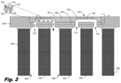
- Fig. 2 is a cross-sectional view of a fluid ejection system (200) according to an example of the principles described herein.
- the fluid ejection system (200) may include a die (100) that may have a number of layers. Among these layers may be an orifice layer (201), a silicon layer (202), and an interposer layer (203).
- the orifice layer (201) may be made of, for example, phosphosilicate glass (PSG), undoped silicate glass (USG), borophosphosilicate glass (BPSG), stainless steel sheet, polymer, or combinations thereof. Other types of material may be used to form the orifice layer (201) and the present specification contemplates the use of those other materials.
- the total thickness across the orifice layer (201), silicon layer (202), and interposer layer (203) may be between 700 and 720 micrometers. In an example, the total thickness across the orifice layer (201), silicon layer (202), and interposer layer (203) may be 710 micrometers.
- the orifice layer (201) may have, formed therethrough, at least one orifice (213).
- the orifice (213) may have any dimensions and is used as a conduit through which a fluid ejection device (210) ejects fluid from the die (100).
- the silicon layer (202) may be made of silicon and may form the portion of the die (100) into which the chamber recirculation channels (120) are formed. Additionally, as can be seen in the cut-away view presented in Fig. 2 , the silicon layer (202) forms a fluid ejection chamber (214) with the orifice layer (201). Positioned inside the fluid ejection chamber (214) and below the orifice (213) is the fluid ejection device (210).
- any of the chamber recirculation channels (120) may include therein a pump (135) to recirculate the fluid from the cross-die recirculation channels (105), through the second-sized inlet port (125), through the fluid ejection chamber (214), across the fluid ejection device (210), and out of the second-sized outlet port (130), and back into the cross-die recirculation channels (105).
- a pump (135) to recirculate the fluid from the cross-die recirculation channels (105), through the second-sized inlet port (125), through the fluid ejection chamber (214), across the fluid ejection device (210), and out of the second-sized outlet port (130), and back into the cross-die recirculation channels (105).
- the interposer layer (203) of the die (100) may, in an example, be made of silicon.
- Fig. 2 shows an example of a cross-die recirculation channel (105) formed, at least partially, through the die (100) and specifically the interposer layer (203) and the silicon layer (202).
- the cross-die recirculation channels (105) may be supplied with fluid via a number of slots (208, 209).
- the slots (208, 209) may be defined by a die carrier (206) made of, for example polyphenylene sulfide (PPS) and liquid crystal polymers (LCP) mixture, and a reverb insert (207) made of, for example, a plastic.
- PPS polyphenylene sulfide
- LCP liquid crystal polymers
- a reverb insert (207) made of, for example, a plastic.
- fluid may be provided into the slots (208, 209) via, for example, a pump.
- the fluid within the slots (208, 209) may be forced through the cross-die recirculation channels (105) as indicated by the fluid flow path (212).
- the pumps (135) within the chamber recirculation channels (120) may then draw an amount of fluid through the chamber recirculation channels (120) as described herein. Unused fluid is pushed back into the cross-die recirculation channels (105) and may be sent back out of the die (100) and into the slots (208, 209). This recirculation prevents the settling of, for example, pigments within the fluid thereby increasing the print quality during a print job.
- the die (100) may be embedded into a substrate (204).
- the substrate (204) may be made of, for example, epoxy mold compound (EMC).
- EMC epoxy mold compound
- Fig. 2 shows the die (100) being embedded into the substrate (204), the present specification contemplates other configurations where the die (100) is coupled to the surface of another substrate material. The present specification contemplates these other arrangements of the die (100).
- the substrate (204) and die (100) may be coupled to the die carrier (206) and reverb inserts (207) via an adhesive.
- the adhesive is an epoxy.
- Fig. 2 shows a cross-die recirculation channel (105) that appears to run the length of the die (100).
- the cross-die recirculation channels (105) may be defined by a number of posts and/or ribs formed laterally (i.e., behind and in front of the chamber recirculation channel (120) shown) along the length of the die (100).
- a number of example layouts of the cross-die recirculation channels (105) formed within the die (100) are described herein.
- Fig. 3 is a block diagram of a device (300) according to an example of the principles described herein.
- the device (300) may include a silicon die (305) having at least one chamber recirculation channel (310) formed therein that is fluidically coupled to a cross-die recirculation channel (325).
- the chamber recirculation channel (310) is fluidically coupled to the cross-die recirculation channel (325) via an inlet port (315) and an outlet port (320).
- Fig. 4 is a block diagram of a fluid ejection system (400) according to an example of the principles described herein.
- the fluid ejection system (400) may include a fluid reservoir (405) fluidically coupled to, at least, a silicon die (410).
- the fluid reservoir (405) provides the printing fluid (455) to the silicon die (410) via the cross-die recirculation channels (415).
- additional channels, slots or tubes may be coupled between the cross-die recirculation channels (415) and the fluid reservoir (405) and the present specification contemplates the use of these other fluidic connections.
- This recirculation of printing fluid (455) through the cross-die recirculation channels (415) and chamber recirculation channels (430) prevent pigments or other solids within the printing fluid (455) from separating from the liquid carrier fluid within the printing fluid (455). Because the pump (450) pumps the printing fluid (455) out of and into the cross-die recirculation channels (415), the printing fluid (455) is continually mixed preventing the separation. Additionally, some of the printing fluid (455) recirculating through the cross-die recirculation channels (415) may not be pulled into the chamber recirculation channels (430).
- Each of the chamber recirculation channels (430) may further include at least one fluid ejection device within the fluid ejection chambers to eject an amount of fluid through an orifice formed on a surface of the silicon die (410) opposite the first sized input port (420) and first sized outlet port (425) of the cross-die recirculation channels (415).
- each of the cross-die recirculation channels (415) may have a plurality of fluid ejection chambers formed therein with each of the fluid ejection chambers including a fluid ejection device and orifice.
- Fig. 5 is a bottom view of a die (500) according to an example of the principles described herein.
- Fig. 5 shows an interposer layer (505) in front of a silicon layer (510).
- orifice layer ( Fig. 2 , 201) is not viewable but, instead, is layered behind the silicon layer (510) as viewed in Fig. 5 .
- the layout of the cross-die recirculation channels (515) presented in Fig. 5 are merely an example and the present specification contemplates other layouts as described herein.
- the cross-die recirculation channels (515) cross-die recirculation channels (515) in the present example are presented in a slanted configuration such that the cross-die recirculation channels (515) enter through the interposer layer (505) and into the silicon layer (510), across the silicon layer (510) at a slant, and back out of the silicon layer (510) and interposer layer (505) at a relatively lower location along the surface of the interposer layer (505).
- Each of the cross-die recirculation channels (515) include an inlet port (520) and an outlet port (525) as described herein. As a result of the view of Fig. 5 , a bottom surface of the silicon layer (510) is seen through the inlet ports (520) and outlet ports (525).
- a cross-die section of the cross-die recirculation channels (515) may be formed through the silicon layer (510) and blocked from view by the interposer layer (505) as indicated by the dashed lines.
- the formation of the cross-die recirculation channels (515) creates ribs (530) between each of the cross-die recirculation channels (515).
- the ribs (530) may provide support between the silicon layer (510) and interposer layer (505).
- the formation of the cross-die recirculation channels (515) in Fig. 5 may be referred to as a cross-flow configuration because the flow of fluid through the cross-die recirculation channels (515) crosses the die (500) laterally.
- the formation of the cross-die recirculation channels (515) may form ribs (530) that are between a 70 and 160 dpi pitch.
- the ribs (530) are at a 150 dpi pitch.
- the ribs (530) are at a 75 dpi pitch.
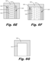
- Figs. 6A-6G show a number of examples of layouts of the cross-die recirculation channels shown in Fig. 5 according to an example of the principles described herein.
- Each of the examples shown in Figs. 6A-6G are examples of a cross-flow configuration because the flow of fluid through the cross-die recirculation channels (515) crosses the die (500) laterally.
- Fig. 6A shows a slanted enclosed slot configuration with each of the cross-die recirculation channels (515) crossing through the silicon layer (510) at an angle.
- the angle may be between 25 to 35 degrees relative to the edge of the silicon die ( Fig. 4 , 410).
- the angle may be 30 degrees relative to the edge of the silicon die ( Fig.
- the width of the rib (530) may be between 70 and 90 micrometers. In an example, the width of the rib (530) may be 80 micrometers. In an example, the width of the cross-die recirculation channels (515) may be between 300 and 500 micrometers. In an example, the width of the cross-die recirculation channels (515) may be 400 micrometers. In the example shown in fig. 6A , the ribs (530) may extend across each of the inlet ports (520) and outlet ports (525).
- the ribs (530) do not extend across the inlet ports (520) and outlet ports (525) and would, therefore, not be viewable through the inlet ports (520) and outlet ports (525) when viewed at the angle seen in Fig. 6A .
- Fig. 6B is an example of the cross-die recirculation channels (515) that are also slanted.
- the inlet ports (520) and outlet ports (525) may be staggered along the ends of the cross-die recirculation channels (515) such that fluid flow (as shown by the arrows) flows from one inlet port (520) through a number of fluid ejection chambers and into a neighboring cross-die recirculation channel (515) before exiting through an outlet port (525).
- Fig. 6C may be a variant of Fig. 6A but instead of slanted ribs (530) and cross-die recirculation channels (515), the ribs (530) and cross-die recirculation channels (515) are perpendicular to an edge surface of the silicon die ( Fig. 4 , 410).
- the fluid may enter the inlet ports (520) pass through the cross-die recirculation channels (515) and exit out of the outlet ports (525).
- the width of the ribs (530) may be 50 micrometers with a cross-die recirculation channels (515) width of 290 micrometers.
- Fig. 6D may be a variant of Fig 6B but instead of slanted ribs (530) and cross-die recirculation channels (515), the ribs (530) and cross-die recirculation channels (515) are perpendicular to an edge surface of the silicon die ( Fig. 4 , 410).
- the fluid may pass into an inlet port (520) pass, at least partially through the cross-die recirculation channel (515) across a fluid ejection chamber, through the cross-die recirculation channels (515) again, and out of an outlet port (525).
- Fig. 6E may be a variant of fig. 6C except that the cross-die recirculation channels (515) are formed into chevrons.
- the angle formed by the chevron-shaped cross-die recirculation channels (515), in an example, may be 30 degrees.
- the fluid may enter the inlet ports (520) pass through the cross-die recirculation channels (515) and exit out of the outlet ports (525).
- the chevron ribs (530) formed by the chevron shaped cross-die recirculation channels (515) may have a width of 80 micrometers with the cross-die recirculation channels (515) having a width of 400 micrometers.
- Fig. 6F shows a number of posts (535) formed within a cross-die recirculation channel (515).
- the posts (535) may be of any size and may vary by pattern including a slanted patter, a chevron pattern, or any other pattern.
- the posts may have a diameter of 100 micrometers.
- the posts may be formed into lines either that are straight, slanted, or chevron shaped.
- Fig. 6G includes a single cross-die recirculation channel (515) that spans across the silicon die ( Fig. 4 , 410) under the orifices of the silicon die ( Fig. 4 , 410) without any ribs (530) or posts (535).
- the inlet ports (520) and outlet ports (525) may be the same port with the cross-die recirculation channel (515) being formed into a single channel.
- the width of the cross-die recirculation channels (515) may be 3.151 millimeters.
- Figs. 7A-7E show a number of examples of layouts of the cross-die recirculation channels shown in Fig. 5 according to an example of the principles described herein.
- Each of the examples shown in Figs. 7A-7E are examples of a longitudinal-flow configuration because the flow of fluid through the cross-die recirculation channels (515) crosses the die (500) longitudinally.
- Fig. 7A shows two cross-die recirculation channels (515) that span the length of the silicon die ( Fig. 4 , 410) longitudinally.
- the inlet ports (520) may be on one end of the silicon die ( Fig. 4 , 410) at the beginning of the cross-die recirculation channels (515).
- the outlet ports (525) may be located at the other end of the silicon die ( Fig. 4 , 410).
- an inlet port (520) and an outlet port (525) for each of the individual cross-die recirculation channels (515) may be on the same end of the silicon die ( Fig. 4 , 410).
- Fig. 7B is a variant of Fig. 7A except that there are multiple cross-die recirculation channels (515) with their inlet ports (520) and outlet ports (525).
- the inlet ports (520) may be on one end of the silicon die ( Fig. 4 , 410) at the beginning of the cross-die recirculation channels (515).
- the outlet ports (525) may be located at the other end of the silicon die ( Fig. 4 , 410).
- an inlet port (520) and an outlet port (525) for each of the individual cross-die recirculation channels (515) may be on the same end of the silicon die ( Fig. 4 , 410).
- Fig. 7C is a variant of Fig. 7A , except in this example the cross-die recirculation channels (515) may include a number of posts (535) within, at least, a portion of the cross-die recirculation channels (515).
- the inlet ports (520) may be on one end of the silicon die ( Fig. 4 , 410) at the beginning of the cross-die recirculation channels (515).
- the outlet ports (525) may be located at the other end of the silicon die ( Fig. 4 , 410).
- an inlet port (520) and an outlet port (525) for each of the individual cross-die recirculation channels (515) may be on the same end of the silicon die ( Fig. 4 , 410).
- Fig. 7D shows a variant of Fig. 7A , except in this example the cross-die recirculation channels (515) may include either an inlet port (520) and/or and outlet port (525) along the length of the cross-die recirculation channels (515).
- Fig. 7E shows a variant of Fig. 7A except in this example, the cross-die recirculation channels (515) span the length of the silicon die ( Fig. 4 , 410) with either an inlet port (520) or outlet port (525) formed along the cross-die recirculation channels (515).
- the square shape of the inlet ports (520) and/or outlet ports (525) may be 1 millimeter by 1.09 millimeters with a distance between any inlet ports (520) and/or outlet ports (525) being 4.91 millimeters. In an example, the square shape of the inlet ports (520) and/or outlet ports (525) may be 1 millimeter by 0.61 millimeters with a distance between any inlet ports (520) and/or outlet ports (525) being 4.91 millimeters.
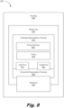
- Fig, 8 is a block diagram of a device (800) according to an example of the principles described herein. Similar to Fig. 3 , the device (800) may include a silicon die (805) having at least one chamber recirculation channel (810) formed therein that is fluidically coupled to a cross-die recirculation channel (825). The chamber recirculation channel (810) is fluidically coupled to the cross-die recirculation channel (825) via an inlet port (815) and an outlet port (820).
- the chamber recirculation channel (810) may pass through a firing chamber (830).
- the firing chamber (830) may include a fluid ejection device such as a thermal resistor or a piezoelectric device.
- the chamber recirculation channel (810) may include a pump (835) to pull an amount of fluid from the cross-die recirculation channel (825) and into the flow of the chamber recirculation channel (810) as described herein.
- the device (800) may further include a housing (840) and a reservoir (845).
- the housing (840) may be coupled to one or more elements of the device (800).
- the silicon die (805) may be directly coupled to the housing (840) thereby supporting the silicon die (805) during operation.
- the housing (840) is made of a plastic.
- the reservoir (845) may be any type of reservoir that can hold a fluid therein.
- fluid is a printing fluid such as inks, toners, varnishes, powders, colorants, finishes, gloss enhancers, binders, and/or other such materials that may be utilized in a printing process.
- the reservoir (845) is fluidically coupled to, at least, the cross-die recirculation channel (825).
- the reservoir (845) may provide an amount of fluid to the cross-die recirculation channel (825) such that the fluid is recirculated through the chamber recirculation channel (810), the cross-die recirculation channel (825), and/or the firing chamber (830) as described herein.
- Various other devices may be used to provide the fluid to at least a number of input ports of the cross-die recirculation channel (825) as described herein.
- the specification and figures describe a cross-die recirculation channel that is fluidically coupled to a chamber recirculation channel used to recirculate fluid through the die.
- Recirculation of the fluid through the die as well as through the firing chambers prevents, in some examples, pigments from separating from the carrier fluids within the fluid.
- the by-pass fluidic flow from the cross-die recirculation channel further prevents decapping due to insufficient fluid being provided to the firing chambers.
- the chamber recirculation channel may further include a pump to pump fluid from the cross-die recirculation channel and through the chamber recirculation channel.
- backside silicon micro channels may be strategically located adjacent to the inkjet architecture region and the fluid velocity through the chamber recirculation channel can transfer heat effectively from silicon die to the fluid to cool off the die.
- Some of the example die formations may be used for single colors of fluid while others may be used for multiple colors.
Landscapes
- Particle Formation And Scattering Control In Inkjet Printers (AREA)
- Ink Jet (AREA)
Claims (14)
- Fluid-Matrize (100, 500), umfassend:mindestens einen in die Matrize (100, 500) eingeformten matrizenquerenden Rückführungskanal (105, 325, 415, 515, 825), wobei der matrizenquerende Rückführungskanal (105, 325, 415, 515, 825) eine Einlassöffnung erster Größe (110, 420) und eine Auslassöffnung erster Größe (115, 425) einschließt, die auf einer ersten Seite der Matrize (100, 500) ausgebildet sind;mindestens einen Kammer-Rückführungskanal (120, 310, 430, 810), der in die Matrize (100, 500) eingeformt ist, wobei der Kammer-Rückführungskanal (120, 310, 430, 810) eine Einlassöffnung zweiter Größe (125, 435) und eine Auslassöffnung zweiter Größe (130, 440) einschließt und wobei die Einlassöffnung zweiter Größe (125, 435) und die Auslassöffnung zweiter Größe (130, 440) fluidisch mit einem Abschnitt des matrizenquerenden Rückführungskanals (105, 325, 415, 515, 825) gekoppelt sind; undmindestens eine Pumpe (135, 335, 450, 835), die innerhalb des Kammer-Rückführungskanals (120, 310, 430, 810) ausgebildet ist.
- Matrize (100, 500) nach Anspruch 1, wobei eine Vielzahl von Farben von Druckfluid (455) fluidisch mit mindestens einem einer Vielzahl der Kammer-Rückführungskanäle (120, 310, 430, 810), die in die Matrize (100, 500) eingeformt sind, gekoppelt sind.
- Matrize (100, 500) nach Anspruch 1, wobei der mindestens eine Kammer-Rückführungskanal (120, 310, 430, 810) durch mindestens eine in der Matrize (100, 500) definierte Abschusskammer (330, 830) geführt ist.
- Matrize (100, 500) nach Anspruch 1, wobei die mindestens eine Pumpe (135, 335, 450, 835) das Druckfluid (455) aus dem matrizenquerenden Rückführungskanal (105, 325, 415, 515, 825) und durch eine in der Matrize (100, 500) ausgebildete Abschusskammer (330, 830) zieht.
- Matrize (100, 500) nach Anspruch 1, wobei der mindestens eine matrizenquerende Rückführungskanal (105, 325, 415, 515, 825) eine seitliche Querströmung über die Matrize (100, 500) hinweg erzeugt, um den mindestens einen Kammer-Rückführungskanal (120, 310, 430, 810) mit dem mindestens einen matrizenquerenden Rückführungskanal (105, 325, 415, 515, 825) zu verbinden.
- Matrize (100, 500) nach Anspruch 1, wobei der mindestens eine matrizenquerende Rückführungskanal (105, 325, 415, 515, 825) in Längsrichtung über die Matrize (100, 500) hinweg verläuft, um den mindestens einen Kammer-Rückführungskanal (120, 310, 430, 810) mit dem mindestens einen matrizenquerenden Rückführungskanal (105, 325, 415, 515, 825) zu verbinden.
- Vorrichtung (300, 800), die umfasst:die Fluid-Matrize (100, 500) nach Anspruch 1; undwobei die Fluid-Matrize (100, 500) eine Silizium-Matrize ist und eine Abschusskammer (330, 830) umfasst, die entlang des mindestens einen Kammer-Rückführungskanals (120, 310, 430, 810) ausgebildet ist;wobei der mindestens eine Kammer-Rückführungskanal (120, 310, 430, 810) in die Silizium-Matrize (305, 410, 805) eingeformt ist; undwobei die mindestens eine Pumpe (135, 335, 450, 835) entlang eines Abschnitts des mindestens einen Kammer-Rückführungskanals (120, 310, 430, 810) ausgebildet ist, um eine Menge des Druckfluids (455) aus dem matrizenquerenden Rückführungskanal (105, 325, 415, 515, 825) und durch die Abschusskammer (330, 830) zu ziehen.
- Vorrichtung (300, 800) nach Anspruch 7, wobei der mindestens eine matrizenquerende Rückführungskanal (105, 325, 415, 515, 825) eine seitliche Querströmung über die Silizium-Matrize (305, 410, 805) hinweg erzeugt, um den mindestens einen Kammer-Rückführungskanal (120, 310, 430, 810) mit dem matrizenquerenden Rückführungskanal (105, 325, 415, 515, 825) zu verbinden.
- Vorrichtung (300, 800) nach Anspruch 7, wobei der mindestens eine matrizenquerende Rückführungskanal (105, 325, 415, 515, 825) in Längsrichtung über die Silizium-Matrize (305, 410, 805) verläuft, um den mindestens einen Kammer-Rückführungskanal (120, 310, 430, 810) mit dem mindestens einen matrizenquerenden Rückführungskanal (105, 325, 415, 515, 825) zu verbinden.
- Vorrichtung (300, 800) nach Anspruch 7, wobei die Vorrichtung (300, 800) in eine Kartusche eingebaut ist.
- Fluidausstoßsystem (200, 400), umfassend:einen Fluidbehälter (405), um eine bestimmte Menge des Druckfluids (455) darin vorzuhalten; unddie Fluid-Matrize (100, 500) nach Anspruch 1, wobei:die Matrize (100, 500) eine Silizium-Matrize ist;der mindestens eine matrizenquerende Rückführungskanal (105, 325, 415, 515, 825) dazu dient, eine Menge des Druckfluids (455) durch diesen hindurch rückzuführen;der mindestens eine Kammer-Rückführungskanal (120, 310, 430, 810) fluidisch mit dem matrizenquerenden Rückführungskanal (105, 325, 415, 515, 825) gekoppelt ist, um eine Menge des Druckfluids (455) durch diesen hindurch rückzuführen; unddie mindestens eine Pumpe (135, 335, 450, 835), die innerhalb des Kammer-Rückführungskanals (120, 310, 430, 810) ausgebildet ist, dazu dient, die Menge des Druckfluids (455) durch diesen hindurch rückzuführen.
- Fluidausstoßsystem (200, 400) nach Anspruch 11, wobei der mindestens eine Kammer-Rückführungskanal (120, 310, 430, 810) durch mindestens eine in der Silizium-Matrize (305, 410, 805) definierte Abschusskammer (330, 830) geführt ist.
- Fluidausstoßsystem (200, 400) nach Anspruch 11, wobei der mindestens eine matrizenquerende Rückführungskanal (105, 325, 415, 515, 825) eine seitliche Querströmung über die Silizium-Matrize (305, 410, 805) hinweg erzeugt, um den mindestens einen Kammer-Rückführungskanal (120, 310, 430, 810) mit dem mindestens einen matrizenquerenden Rückführungskanal (105, 325, 415, 515, 825) zu verbinden.
- Fluidausstoßsystem (200, 400) nach Anspruch 11, wobei der mindestens eine matrizenquerende Rückführungskanal (105, 325, 415, 515, 825) in Längsrichtung über die Silizium-Matrize (305, 410, 805) verläuft, um den mindestens einen Kammer-Rückführungskanal (120, 310, 430, 810) mit dem mindestens einen matrizenquerenden Rückführungskanal (105, 325, 415, 515, 825) zu verbinden.
Applications Claiming Priority (1)
| Application Number | Priority Date | Filing Date | Title |
|---|---|---|---|
| PCT/US2017/063275 WO2019103752A1 (en) | 2017-11-27 | 2017-11-27 | Cross-die recirculation channels and chamber recirculation channels |
Publications (3)
| Publication Number | Publication Date |
|---|---|
| EP3717258A1 EP3717258A1 (de) | 2020-10-07 |
| EP3717258A4 EP3717258A4 (de) | 2021-06-23 |
| EP3717258B1 true EP3717258B1 (de) | 2025-04-30 |
Family
ID=66631123
Family Applications (1)
| Application Number | Title | Priority Date | Filing Date |
|---|---|---|---|
| EP17932868.7A Active EP3717258B1 (de) | 2017-11-27 | 2017-11-27 | Chipübergreifende rezirkulationskanäle und kammerrezirkulationskanäle |
Country Status (5)
| Country | Link |
|---|---|
| US (1) | US11065883B2 (de) |
| EP (1) | EP3717258B1 (de) |
| JP (1) | JP6964775B2 (de) |
| CN (1) | CN111372782B (de) |
| WO (1) | WO2019103752A1 (de) |
Families Citing this family (3)
| Publication number | Priority date | Publication date | Assignee | Title |
|---|---|---|---|---|
| US9090084B2 (en) * | 2010-05-21 | 2015-07-28 | Hewlett-Packard Development Company, L.P. | Fluid ejection device including recirculation system |
| CN110891793B (zh) * | 2017-07-31 | 2021-04-09 | 惠普发展公司,有限责任合伙企业 | 具有封闭式横向通道的流体喷射管芯 |
| US11807019B2 (en) | 2019-07-31 | 2023-11-07 | Hewlett-Packard Development Company, L.P. | Printing fluid circulation |
Family Cites Families (24)
| Publication number | Priority date | Publication date | Assignee | Title |
|---|---|---|---|---|
| US5017941A (en) | 1989-11-06 | 1991-05-21 | Xerox Corporation | Thermal ink jet printhead with recirculating cooling system |
| KR100891114B1 (ko) * | 2007-03-23 | 2009-03-30 | 삼성전자주식회사 | 잉크젯 프린트헤드 및 이를 이용한 인쇄 방법, 잉크젯프린트헤드의 제조방법 |
| JP2009154328A (ja) * | 2007-12-25 | 2009-07-16 | Fuji Xerox Co Ltd | 液滴吐出ヘッド及びこれを備えた画像形成装置 |
| JP5369176B2 (ja) | 2008-05-23 | 2013-12-18 | 富士フイルム株式会社 | 流体液滴を吐出するための流体の循環 |
| US8113628B2 (en) * | 2009-06-19 | 2012-02-14 | Eastman Kodak Company | Inkjet printers having micro-fluidic actuators |
| US8182073B2 (en) | 2009-06-30 | 2012-05-22 | Eastman Kodak Company | Flow through dispenser including diverter cooling channel |
| US8540355B2 (en) * | 2010-07-11 | 2013-09-24 | Hewlett-Packard Development Company, L.P. | Fluid ejection device with circulation pump |
| US9090084B2 (en) * | 2010-05-21 | 2015-07-28 | Hewlett-Packard Development Company, L.P. | Fluid ejection device including recirculation system |
| BR112013000372B1 (pt) | 2010-07-28 | 2020-11-03 | Hewlett-Packard Development Company, L. P | conjuntos de ejeção de fluido |
| EP3381698B1 (de) * | 2010-10-19 | 2020-04-08 | Hewlett-Packard Development Company, L.P. | Druckmodul mit zweifachregler |
| US8657420B2 (en) * | 2010-12-28 | 2014-02-25 | Fujifilm Corporation | Fluid recirculation in droplet ejection devices |
| KR20140048159A (ko) * | 2011-06-29 | 2014-04-23 | 휴렛-팩커드 디벨롭먼트 컴퍼니, 엘.피. | 압전 인쇄헤드 트레이스 레이아웃 |
| CN103781630B (zh) * | 2011-08-31 | 2016-06-01 | 惠普发展公司,有限责任合伙企业 | 具有流体位移致动器的流体喷射装置和相关方法 |
| US9211721B2 (en) | 2011-09-28 | 2015-12-15 | Hewlett-Packard Development Company, L.P. | Slot-to-slot circulation in a fluid ejection device |
| JP2013103485A (ja) * | 2011-11-16 | 2013-05-30 | Ricoh Co Ltd | 画像形成装置 |
| JP6128820B2 (ja) * | 2011-12-22 | 2017-05-17 | キヤノン株式会社 | 液体吐出ヘッド |
| US9162453B2 (en) | 2012-07-30 | 2015-10-20 | Hewlett-Packard Development Company, L.P. | Printhead including integrated circuit die cooling |
| JP2014151528A (ja) * | 2013-02-07 | 2014-08-25 | Canon Inc | 液体吐出記録装置 |
| US9381739B2 (en) * | 2013-02-28 | 2016-07-05 | Hewlett-Packard Development Company, L.P. | Fluid ejection assembly with circulation pump |
| JP6794239B2 (ja) * | 2016-01-08 | 2020-12-02 | キヤノン株式会社 | 液体吐出装置および液体吐出ヘッド |
| JP7013124B2 (ja) * | 2016-01-08 | 2022-01-31 | キヤノン株式会社 | 液体吐出ヘッドの製造方法 |
| JP2017140806A (ja) * | 2016-02-12 | 2017-08-17 | キヤノン株式会社 | 液体吐出ヘッドおよび液体吐出装置 |
| JP6732465B2 (ja) * | 2016-02-15 | 2020-07-29 | キヤノン株式会社 | 液体吐出ヘッドおよび液体吐出装置 |
| JP6719918B2 (ja) | 2016-02-17 | 2020-07-08 | キヤノン株式会社 | 液体吐出ヘッド及び液体吐出装置 |
-
2017
- 2017-11-27 CN CN201780097255.6A patent/CN111372782B/zh active Active
- 2017-11-27 WO PCT/US2017/063275 patent/WO2019103752A1/en not_active Ceased
- 2017-11-27 US US16/493,045 patent/US11065883B2/en active Active
- 2017-11-27 JP JP2020528423A patent/JP6964775B2/ja not_active Expired - Fee Related
- 2017-11-27 EP EP17932868.7A patent/EP3717258B1/de active Active
Also Published As
| Publication number | Publication date |
|---|---|
| US11065883B2 (en) | 2021-07-20 |
| JP2021504188A (ja) | 2021-02-15 |
| EP3717258A1 (de) | 2020-10-07 |
| US20200282738A1 (en) | 2020-09-10 |
| JP6964775B2 (ja) | 2021-11-10 |
| WO2019103752A1 (en) | 2019-05-31 |
| CN111372782A (zh) | 2020-07-03 |
| EP3717258A4 (de) | 2021-06-23 |
| CN111372782B (zh) | 2021-10-29 |
Similar Documents
| Publication | Publication Date | Title |
|---|---|---|
| US11987055B2 (en) | Fluidic dies | |
| EP3609712B1 (de) | Fluidische ausstossvorrichtungen mit geschlossenen kanälen | |
| US11654680B2 (en) | Fluidic ejection dies with enclosed cross-channels | |
| US11065883B2 (en) | Cross-die recirculation channels and chamber recirculation channels | |
| US11691431B2 (en) | Fluid circulation and ejection | |
| EP3661750B1 (de) | Fluidische matrizen mit einlass- und auslasskanälen | |
| CN109641456B (zh) | 包括流体输出通道的流体喷射设备 | |
| JP7317560B2 (ja) | 液体吐出ヘッド、液体吐出モジュールおよび液体吐出装置 | |
| US20230025124A1 (en) | Recirculation fluid ejection device | |
| US12434478B2 (en) | Compact inkjet nozzle device with high degree of symmetry | |
| US20210061644A1 (en) | Mems inkjet printhead having recirculating ink pathway | |
| JP7271320B2 (ja) | 液体吐出ヘッド、液体吐出モジュール、液体吐出装置、および液体吐出ヘッドの製造方法 | |
| US20210039391A1 (en) | Fluid ejection unit with circulation loop and fluid bypass |
Legal Events
| Date | Code | Title | Description |
|---|---|---|---|
| STAA | Information on the status of an ep patent application or granted ep patent |
Free format text: STATUS: THE INTERNATIONAL PUBLICATION HAS BEEN MADE |
|
| PUAI | Public reference made under article 153(3) epc to a published international application that has entered the european phase |
Free format text: ORIGINAL CODE: 0009012 |
|
| STAA | Information on the status of an ep patent application or granted ep patent |
Free format text: STATUS: REQUEST FOR EXAMINATION WAS MADE |
|
| 17P | Request for examination filed |
Effective date: 20200430 |
|
| AK | Designated contracting states |
Kind code of ref document: A1 Designated state(s): AL AT BE BG CH CY CZ DE DK EE ES FI FR GB GR HR HU IE IS IT LI LT LU LV MC MK MT NL NO PL PT RO RS SE SI SK SM TR |
|
| AX | Request for extension of the european patent |
Extension state: BA ME |
|
| DAV | Request for validation of the european patent (deleted) | ||
| DAX | Request for extension of the european patent (deleted) | ||
| A4 | Supplementary search report drawn up and despatched |
Effective date: 20210527 |
|
| RIC1 | Information provided on ipc code assigned before grant |
Ipc: B41J 2/14 20060101AFI20210520BHEP Ipc: B41J 2/18 20060101ALI20210520BHEP Ipc: B41J 2/165 20060101ALI20210520BHEP |
|
| STAA | Information on the status of an ep patent application or granted ep patent |
Free format text: STATUS: EXAMINATION IS IN PROGRESS |
|
| 17Q | First examination report despatched |
Effective date: 20221004 |
|
| GRAP | Despatch of communication of intention to grant a patent |
Free format text: ORIGINAL CODE: EPIDOSNIGR1 |
|
| STAA | Information on the status of an ep patent application or granted ep patent |
Free format text: STATUS: GRANT OF PATENT IS INTENDED |
|
| GRAS | Grant fee paid |
Free format text: ORIGINAL CODE: EPIDOSNIGR3 |
|
| INTG | Intention to grant announced |
Effective date: 20250214 |
|
| GRAA | (expected) grant |
Free format text: ORIGINAL CODE: 0009210 |
|
| STAA | Information on the status of an ep patent application or granted ep patent |
Free format text: STATUS: THE PATENT HAS BEEN GRANTED |
|
| AK | Designated contracting states |
Kind code of ref document: B1 Designated state(s): AL AT BE BG CH CY CZ DE DK EE ES FI FR GB GR HR HU IE IS IT LI LT LU LV MC MK MT NL NO PL PT RO RS SE SI SK SM TR |
|
| REG | Reference to a national code |
Ref country code: CH Ref legal event code: EP Ref country code: GB Ref legal event code: FG4D |
|
| REG | Reference to a national code |
Ref country code: DE Ref legal event code: R096 Ref document number: 602017089262 Country of ref document: DE |
|
| REG | Reference to a national code |
Ref country code: IE Ref legal event code: FG4D |
|
| REG | Reference to a national code |
Ref country code: NL Ref legal event code: MP Effective date: 20250430 |
|
| REG | Reference to a national code |
Ref country code: AT Ref legal event code: MK05 Ref document number: 1789687 Country of ref document: AT Kind code of ref document: T Effective date: 20250430 |
|
| PG25 | Lapsed in a contracting state [announced via postgrant information from national office to epo] |
Ref country code: FI Free format text: LAPSE BECAUSE OF FAILURE TO SUBMIT A TRANSLATION OF THE DESCRIPTION OR TO PAY THE FEE WITHIN THE PRESCRIBED TIME-LIMIT Effective date: 20250430 Ref country code: PT Free format text: LAPSE BECAUSE OF FAILURE TO SUBMIT A TRANSLATION OF THE DESCRIPTION OR TO PAY THE FEE WITHIN THE PRESCRIBED TIME-LIMIT Effective date: 20250901 Ref country code: ES Free format text: LAPSE BECAUSE OF FAILURE TO SUBMIT A TRANSLATION OF THE DESCRIPTION OR TO PAY THE FEE WITHIN THE PRESCRIBED TIME-LIMIT Effective date: 20250430 |
|
| REG | Reference to a national code |
Ref country code: LT Ref legal event code: MG9D |
|
| PG25 | Lapsed in a contracting state [announced via postgrant information from national office to epo] |
Ref country code: NO Free format text: LAPSE BECAUSE OF FAILURE TO SUBMIT A TRANSLATION OF THE DESCRIPTION OR TO PAY THE FEE WITHIN THE PRESCRIBED TIME-LIMIT Effective date: 20250730 Ref country code: GR Free format text: LAPSE BECAUSE OF FAILURE TO SUBMIT A TRANSLATION OF THE DESCRIPTION OR TO PAY THE FEE WITHIN THE PRESCRIBED TIME-LIMIT Effective date: 20250731 |
|
| PG25 | Lapsed in a contracting state [announced via postgrant information from national office to epo] |
Ref country code: PL Free format text: LAPSE BECAUSE OF FAILURE TO SUBMIT A TRANSLATION OF THE DESCRIPTION OR TO PAY THE FEE WITHIN THE PRESCRIBED TIME-LIMIT Effective date: 20250430 Ref country code: NL Free format text: LAPSE BECAUSE OF FAILURE TO SUBMIT A TRANSLATION OF THE DESCRIPTION OR TO PAY THE FEE WITHIN THE PRESCRIBED TIME-LIMIT Effective date: 20250430 |
|
| PG25 | Lapsed in a contracting state [announced via postgrant information from national office to epo] |
Ref country code: BG Free format text: LAPSE BECAUSE OF FAILURE TO SUBMIT A TRANSLATION OF THE DESCRIPTION OR TO PAY THE FEE WITHIN THE PRESCRIBED TIME-LIMIT Effective date: 20250430 |
|
| PG25 | Lapsed in a contracting state [announced via postgrant information from national office to epo] |
Ref country code: HR Free format text: LAPSE BECAUSE OF FAILURE TO SUBMIT A TRANSLATION OF THE DESCRIPTION OR TO PAY THE FEE WITHIN THE PRESCRIBED TIME-LIMIT Effective date: 20250430 |
|
| PG25 | Lapsed in a contracting state [announced via postgrant information from national office to epo] |
Ref country code: AT Free format text: LAPSE BECAUSE OF FAILURE TO SUBMIT A TRANSLATION OF THE DESCRIPTION OR TO PAY THE FEE WITHIN THE PRESCRIBED TIME-LIMIT Effective date: 20250430 |
|
| PG25 | Lapsed in a contracting state [announced via postgrant information from national office to epo] |
Ref country code: RS Free format text: LAPSE BECAUSE OF FAILURE TO SUBMIT A TRANSLATION OF THE DESCRIPTION OR TO PAY THE FEE WITHIN THE PRESCRIBED TIME-LIMIT Effective date: 20250731 |
|
| PG25 | Lapsed in a contracting state [announced via postgrant information from national office to epo] |
Ref country code: IS Free format text: LAPSE BECAUSE OF FAILURE TO SUBMIT A TRANSLATION OF THE DESCRIPTION OR TO PAY THE FEE WITHIN THE PRESCRIBED TIME-LIMIT Effective date: 20250830 |
|
| PG25 | Lapsed in a contracting state [announced via postgrant information from national office to epo] |
Ref country code: LV Free format text: LAPSE BECAUSE OF FAILURE TO SUBMIT A TRANSLATION OF THE DESCRIPTION OR TO PAY THE FEE WITHIN THE PRESCRIBED TIME-LIMIT Effective date: 20250430 |
|
| PGFP | Annual fee paid to national office [announced via postgrant information from national office to epo] |
Ref country code: DE Payment date: 20251022 Year of fee payment: 9 |
|
| PG25 | Lapsed in a contracting state [announced via postgrant information from national office to epo] |
Ref country code: DK Free format text: LAPSE BECAUSE OF FAILURE TO SUBMIT A TRANSLATION OF THE DESCRIPTION OR TO PAY THE FEE WITHIN THE PRESCRIBED TIME-LIMIT Effective date: 20250430 Ref country code: SM Free format text: LAPSE BECAUSE OF FAILURE TO SUBMIT A TRANSLATION OF THE DESCRIPTION OR TO PAY THE FEE WITHIN THE PRESCRIBED TIME-LIMIT Effective date: 20250430 |
|
| PG25 | Lapsed in a contracting state [announced via postgrant information from national office to epo] |
Ref country code: CZ Free format text: LAPSE BECAUSE OF FAILURE TO SUBMIT A TRANSLATION OF THE DESCRIPTION OR TO PAY THE FEE WITHIN THE PRESCRIBED TIME-LIMIT Effective date: 20250430 |
|
| PG25 | Lapsed in a contracting state [announced via postgrant information from national office to epo] |
Ref country code: EE Free format text: LAPSE BECAUSE OF FAILURE TO SUBMIT A TRANSLATION OF THE DESCRIPTION OR TO PAY THE FEE WITHIN THE PRESCRIBED TIME-LIMIT Effective date: 20250430 |
|
| PG25 | Lapsed in a contracting state [announced via postgrant information from national office to epo] |
Ref country code: SK Free format text: LAPSE BECAUSE OF FAILURE TO SUBMIT A TRANSLATION OF THE DESCRIPTION OR TO PAY THE FEE WITHIN THE PRESCRIBED TIME-LIMIT Effective date: 20250430 Ref country code: RO Free format text: LAPSE BECAUSE OF FAILURE TO SUBMIT A TRANSLATION OF THE DESCRIPTION OR TO PAY THE FEE WITHIN THE PRESCRIBED TIME-LIMIT Effective date: 20250430 |
|
| PG25 | Lapsed in a contracting state [announced via postgrant information from national office to epo] |
Ref country code: IT Free format text: LAPSE BECAUSE OF FAILURE TO SUBMIT A TRANSLATION OF THE DESCRIPTION OR TO PAY THE FEE WITHIN THE PRESCRIBED TIME-LIMIT Effective date: 20250430 |
|
| REG | Reference to a national code |
Ref country code: DE Ref legal event code: R097 Ref document number: 602017089262 Country of ref document: DE |
|
| PLBE | No opposition filed within time limit |
Free format text: ORIGINAL CODE: 0009261 |
|
| STAA | Information on the status of an ep patent application or granted ep patent |
Free format text: STATUS: NO OPPOSITION FILED WITHIN TIME LIMIT |
|
| REG | Reference to a national code |
Ref country code: CH Ref legal event code: L10 Free format text: ST27 STATUS EVENT CODE: U-0-0-L10-L00 (AS PROVIDED BY THE NATIONAL OFFICE) Effective date: 20260311 |
|
| 26N | No opposition filed |
Effective date: 20260202 |