EP3715677A1 - Flurförderzeug mit einem hydrostatischen fahrantrieb - Google Patents
Flurförderzeug mit einem hydrostatischen fahrantrieb Download PDFInfo
- Publication number
- EP3715677A1 EP3715677A1 EP20160865.0A EP20160865A EP3715677A1 EP 3715677 A1 EP3715677 A1 EP 3715677A1 EP 20160865 A EP20160865 A EP 20160865A EP 3715677 A1 EP3715677 A1 EP 3715677A1
- Authority
- EP
- European Patent Office
- Prior art keywords
- brake pedal
- hydrostatic
- industrial truck
- actuation
- actuated
- Prior art date
- Legal status (The legal status is an assumption and is not a legal conclusion. Google has not performed a legal analysis and makes no representation as to the accuracy of the status listed.)
- Granted
Links
Images

Classifications
-
- F—MECHANICAL ENGINEERING; LIGHTING; HEATING; WEAPONS; BLASTING
- F16—ENGINEERING ELEMENTS AND UNITS; GENERAL MEASURES FOR PRODUCING AND MAINTAINING EFFECTIVE FUNCTIONING OF MACHINES OR INSTALLATIONS; THERMAL INSULATION IN GENERAL
- F16H—GEARING
- F16H61/00—Control functions within control units of change-speed- or reversing-gearings for conveying rotary motion ; Control of exclusively fluid gearing, friction gearing, gearings with endless flexible members or other particular types of gearing
- F16H61/38—Control of exclusively fluid gearing
- F16H61/40—Control of exclusively fluid gearing hydrostatic
- F16H61/4157—Control of braking, e.g. preventing pump over-speeding when motor acts as a pump
-
- B—PERFORMING OPERATIONS; TRANSPORTING
- B60—VEHICLES IN GENERAL
- B60T—VEHICLE BRAKE CONTROL SYSTEMS OR PARTS THEREOF; BRAKE CONTROL SYSTEMS OR PARTS THEREOF, IN GENERAL; ARRANGEMENT OF BRAKING ELEMENTS ON VEHICLES IN GENERAL; PORTABLE DEVICES FOR PREVENTING UNWANTED MOVEMENT OF VEHICLES; VEHICLE MODIFICATIONS TO FACILITATE COOLING OF BRAKES
- B60T1/00—Arrangements of braking elements, i.e. of those parts where braking effect occurs specially for vehicles
- B60T1/02—Arrangements of braking elements, i.e. of those parts where braking effect occurs specially for vehicles acting by retarding wheels
- B60T1/06—Arrangements of braking elements, i.e. of those parts where braking effect occurs specially for vehicles acting by retarding wheels acting otherwise than on tread, e.g. employing rim, drum, disc, or transmission or on double wheels
- B60T1/062—Arrangements of braking elements, i.e. of those parts where braking effect occurs specially for vehicles acting by retarding wheels acting otherwise than on tread, e.g. employing rim, drum, disc, or transmission or on double wheels acting on transmission parts
-
- B—PERFORMING OPERATIONS; TRANSPORTING
- B60—VEHICLES IN GENERAL
- B60T—VEHICLE BRAKE CONTROL SYSTEMS OR PARTS THEREOF; BRAKE CONTROL SYSTEMS OR PARTS THEREOF, IN GENERAL; ARRANGEMENT OF BRAKING ELEMENTS ON VEHICLES IN GENERAL; PORTABLE DEVICES FOR PREVENTING UNWANTED MOVEMENT OF VEHICLES; VEHICLE MODIFICATIONS TO FACILITATE COOLING OF BRAKES
- B60T1/00—Arrangements of braking elements, i.e. of those parts where braking effect occurs specially for vehicles
- B60T1/02—Arrangements of braking elements, i.e. of those parts where braking effect occurs specially for vehicles acting by retarding wheels
- B60T1/08—Arrangements of braking elements, i.e. of those parts where braking effect occurs specially for vehicles acting by retarding wheels using fluid or powdered medium
- B60T1/093—Arrangements of braking elements, i.e. of those parts where braking effect occurs specially for vehicles acting by retarding wheels using fluid or powdered medium in hydrostatic, i.e. positive displacement, retarders
-
- B—PERFORMING OPERATIONS; TRANSPORTING
- B60—VEHICLES IN GENERAL
- B60T—VEHICLE BRAKE CONTROL SYSTEMS OR PARTS THEREOF; BRAKE CONTROL SYSTEMS OR PARTS THEREOF, IN GENERAL; ARRANGEMENT OF BRAKING ELEMENTS ON VEHICLES IN GENERAL; PORTABLE DEVICES FOR PREVENTING UNWANTED MOVEMENT OF VEHICLES; VEHICLE MODIFICATIONS TO FACILITATE COOLING OF BRAKES
- B60T7/00—Brake-action initiating means
- B60T7/02—Brake-action initiating means for personal initiation
- B60T7/04—Brake-action initiating means for personal initiation foot actuated
- B60T7/042—Brake-action initiating means for personal initiation foot actuated by electrical means, e.g. using travel or force sensors
-
- B—PERFORMING OPERATIONS; TRANSPORTING
- B60—VEHICLES IN GENERAL
- B60T—VEHICLE BRAKE CONTROL SYSTEMS OR PARTS THEREOF; BRAKE CONTROL SYSTEMS OR PARTS THEREOF, IN GENERAL; ARRANGEMENT OF BRAKING ELEMENTS ON VEHICLES IN GENERAL; PORTABLE DEVICES FOR PREVENTING UNWANTED MOVEMENT OF VEHICLES; VEHICLE MODIFICATIONS TO FACILITATE COOLING OF BRAKES
- B60T7/00—Brake-action initiating means
- B60T7/02—Brake-action initiating means for personal initiation
- B60T7/08—Brake-action initiating means for personal initiation hand actuated
- B60T7/10—Disposition of hand control
- B60T7/102—Disposition of hand control by means of a tilting lever
-
- B—PERFORMING OPERATIONS; TRANSPORTING
- B60—VEHICLES IN GENERAL
- B60Y—INDEXING SCHEME RELATING TO ASPECTS CROSS-CUTTING VEHICLE TECHNOLOGY
- B60Y2200/00—Type of vehicle
- B60Y2200/10—Road Vehicles
- B60Y2200/15—Fork lift trucks, Industrial trucks
-
- F—MECHANICAL ENGINEERING; LIGHTING; HEATING; WEAPONS; BLASTING
- F16—ENGINEERING ELEMENTS AND UNITS; GENERAL MEASURES FOR PRODUCING AND MAINTAINING EFFECTIVE FUNCTIONING OF MACHINES OR INSTALLATIONS; THERMAL INSULATION IN GENERAL
- F16H—GEARING
- F16H61/00—Control functions within control units of change-speed- or reversing-gearings for conveying rotary motion ; Control of exclusively fluid gearing, friction gearing, gearings with endless flexible members or other particular types of gearing
- F16H61/38—Control of exclusively fluid gearing
- F16H61/40—Control of exclusively fluid gearing hydrostatic
- F16H61/42—Control of exclusively fluid gearing hydrostatic involving adjustment of a pump or motor with adjustable output or capacity
- F16H61/435—Pump capacity control by electric actuators
Definitions
- the invention relates to an industrial truck with a hydrostatic drive, which can be controlled by means of an accelerator pedal device, with the hydrostatic braking of the truck by the hydrostatic drive by applying, in particular a withdrawal, the accelerator pedal device in the direction of a neutral position, and with an auxiliary brake system that is operated by means of a Brake pedal device is controllable.
- hydrostatic drive in particular a hydrostatic drive in which a hydraulic pump is connected to at least one hydraulic motor in a closed circuit
- a hydrostatic drive is used to brake the truck hydrostatically.
- the hydrostatic drive can be controlled here as a rule by means of an accelerator pedal device, for example a double pedal arrangement, with which the direction of travel and the speed of travel of the industrial truck can be specified and adjusted. By moving the accelerator pedal device back into a neutral position for the truck to come to a standstill, the truck is hydrostatically braked and decelerated by means of the hydrostatic travel drive.
- auxiliary brake system that can be controlled by means of a brake pedal device.
- the auxiliary brake system has the function of a parking brake with which the industrial truck can be held at a standstill.
- a quick release of the accelerator pedal device when the truck is traveling at high speed leads to a strong deceleration of the truck in order to be able to meet the legal requirements with regard to the braking of the truck.
- a too fast withdrawal of the accelerator pedal device with an associated excessive deceleration of the industrial truck can occur, for example, in the case of an inexperienced operator if the operator's foot unintentionally slips off the accelerator pedal device.
- the set and predetermined deceleration of the industrial truck when the accelerator pedal device is withdrawn by means of the hydrostatic travel drive is perceived by the operators as too high in certain applications of industrial trucks.
- a reduced and reduced hydrostatic braking deceleration by the hydrostatic drive when releasing the accelerator pedal device would be possible if a second redundant service brake is provided in addition to the service brake formed by the hydrostatic drive, for example a mechanical service brake.
- a second redundant service brake is provided in addition to the service brake formed by the hydrostatic drive, for example a mechanical service brake.
- Such a combination brake system which has two redundant service brakes, however, leads to a high construction outlay for the industrial truck.
- the present invention is based on the object of providing an industrial truck of the type mentioned at the outset, in which the hydrostatic braking can be easily adapted by the hydrostatic travel drive.
- the hydrostatic deceleration of the industrial truck by the hydrostatic travel drive can be adjusted by actuating the brake pedal device and the auxiliary brake system can be actuated in a braking position
- the brake pedal device having a first actuation range in which the hydrostatic deceleration can be adjusted by the hydrostatic travel drive and the auxiliary brake system is not actuated, and has a second actuation area adjoining the first actuation area, in which the auxiliary brake system can be actuated in the direction of a braking position.
- the invention is based on the idea that the hydrostatic deceleration of the industrial truck by the hydrostatic drive when the accelerator pedal device is withdrawn can be reduced if the hydrostatic braking generated by the hydrostatic drive is amplified by a further operating element, in the present case the Brake pedal device that controls the auxiliary braking system.
- the hydrostatic braking deceleration by the hydrostatic drive can be reduced to a lower limit value in terms of control technology when the accelerator pedal device is withdrawn, in order to allow the truck to be braked gently by the To achieve hydrostatic braking when the accelerator pedal device is withdrawn into the neutral position.
- the hydrostatic braking by the hydrostatic drive can be increased and thus intensified, and the hydrostatic deceleration of the industrial truck can be increased by the hydrostatic drive in order to comply with the legal regulations regarding braking deceleration and braking distance.
- the invention is not a complex combination brake system, since the required braking deceleration of the industrial truck is applied exclusively via the hydrostatic travel drive forming the service brake.
- the brake pedal device has a brake pedal which is arranged to be pivotable about a pivot axis, a sensor device being provided which detects the pivoting movement of the brake pedal about the pivot axis and which is connected to an electronic control device controlling the hydrostatic travel drive, and an actuating lever which is arranged pivotably about a further pivot axis and actuates the auxiliary brake system, the brake pedal not actuating the actuating lever in the first actuating range and the brake pedal actuating the actuating lever in the second actuating range.
- the brake pedal device thus consists of the brake pedal and the actuating lever which can be actuated by means of the brake pedal and which controls the auxiliary brake system.
- the actuation lever In the first actuation range of the brake pedal, only the brake pedal is actuated and the hydrostatic deceleration of the industrial truck can be adjusted and increased by means of the hydrostatic drive using the sensor device in conjunction with the electronic control device. In the second actuation area of the brake pedal, the actuation lever is then actuated and thus the auxiliary brake system is activated.
- the actuation path of the brake pedal is thus divided into two actuation areas by means of the actuation lever forming an additional mechanism, with only the brake pedal being actuated in the first actuation area in order to be able to adjust the hydrostatic deceleration of the industrial truck by means of the hydrostatic travel drive in conjunction with the sensor device, and in the second actuation area adjoining the first actuation area, the actuation lever is also actuated by the brake pedal in order to actuate the auxiliary brake system.
- the brake pedal in the first actuation area does not have any mechanical contact with the actuation lever that is in a neutral position and the brake pedal arrives at the end of the first operating area with the operating lever located in the neutral position in mechanical contact. In this way, it is achieved in a simple manner that the actuating lever is actuated by the brake pedal only in the second actuation area in order to actuate the auxiliary brake system.
- the brake pedal is preferably urged into a neutral position by means of a spring device. As a result, the brake pedal can be actuated into the neutral position in a simple manner in the non-actuated state.
- the actuating lever is urged into a neutral position by means of a spring device.
- a spring device which actuates the actuating lever into the neutral position, a pressure point can be achieved in a simple manner when the brake pedal comes into mechanical contact with the actuating lever located in the neutral position at the end of the first actuation range. With the pressure point, the operator operating the brake pedal can thus easily feel the transition from the first operating area to the second operating area of the brake pedal.
- a spring device is advantageously arranged between the brake pedal and the actuating lever. With such a spring device arranged between the brake pedal and the actuation lever, which is actuated only in the first actuation area of the brake pedal, the operator actuating the brake pedal can easily be given a force feedback on the brake pedal in the first actuation area.
- an actuating element is arranged on the brake pedal, by means of which the actuating lever can be actuated in the second actuating area.
- an actuator can be on simple Way in the second operating range of the brake pedal of the operating lever are operated.
- the actuating element is designed as a roller rotatably arranged on the brake pedal.
- the friction between the brake pedal and the actuating lever when it is actuated by the brake pedal can be kept low, and a sensitive actuation of the actuating lever by the brake pedal can be achieved.
- the electronic control device controlling the hydrostatic drive is designed such that when the accelerator pedal device controlling the hydrostatic drive is actuated in the direction of a neutral position, the hydrostatic drive is controlled in such a way that the industrial truck brakes according to a minimum deceleration, and when it is actuated of the brake pedal in the first actuation range, the deceleration of the industrial truck is increased by the hydrostatic drive based on the minimum deceleration as a function of the signal from the sensor device.
- the hydrostatic deceleration of the truck takes place by means of the hydrostatic drive according to a minimum deceleration, so that a gentle braking behavior of the truck is achieved when the accelerator is withdrawn.
- the hydrostatic deceleration by the hydrostatic drive can be increased in a simple manner by evaluating the signal from the sensor device, and thus the hydrostatic deceleration by the hydrostatic drive can be increased.
- the electronic control device is preferably designed in such a way that with increasing actuation of the brake pedal in the first actuation area, the deceleration of the industrial truck is increased by the hydrostatic drive. This enables intuitive operation of the industrial truck, since in the first actuation range of the brake pedal the hydrostatic deceleration is increased by the hydrostatic travel drive from the minimum to a maximum deceleration as the brake pedal is actuated.
- the minimum delay can be set. If the minimum deceleration according to which the industrial truck with the hydrostatic drive is braked when the accelerator pedal device is returned to the neutral position is adjustable, the braking behavior of the industrial truck can easily be adapted to different applications of the industrial truck and / or to the wishes of the operator.
- the actuation lever can actuate the auxiliary brake system mechanically or hydraulically or pneumatically or electrically.
- Mechanical actuation of the auxiliary brake system can be implemented, for example, by means of a cable pull, a linkage or a cam disk.
- Hydraulic actuation of the auxiliary brake system can be implemented, for example, by a master cylinder actuated by the actuating lever.
- a pneumatic actuation of the auxiliary brake system can be implemented, for example, by a brake booster actuated by the actuating lever.
- An electrical actuation of the auxiliary brake system can be implemented, for example, by a solenoid valve or an electromagnetic brake device.
- the hydrostatic travel drive 2 has a variable displacement pump 3 which can be adjusted in terms of delivery volume and which is driven by a drive motor 4, for example an internal combustion engine.
- a drive motor 4 for example an internal combustion engine.
- the variable displacement pump 3 is connected in a closed circuit to one or more hydraulic motors 6, which are in driving connection via an output shaft 7 with a drive wheel 8 of the industrial truck.
- the variable displacement pump 3 has a delivery volume adjusting device 3a, for example a swash plate with adjustable inclination of a variable displacement pump 3 designed as a swash plate machine.
- the delivery volume adjusting device 3a is electrically controlled and is connected to an electronic control device 10 for control.
- the electronic control device 10 is connected on the input side to an accelerator pedal device 11 with which the hydrostatic drive 2 can be controlled.
- the accelerator pedal device 11 is designed in the illustrated embodiment as a double pedal control with two accelerator pedals 11a, 11b.
- the forward travel of the industrial truck 1 can be controlled with the accelerator pedal 11a and the reverse travel of the industrial truck 1 can be controlled with the accelerator pedal 11b.
- variable displacement pump 3 When the operator actuates the accelerator pedal 11a or 11b, a speed setpoint value for forward travel or reverse travel is specified and the delivery volume adjusting device 3a of the variable displacement pump 3 is activated accordingly by the electronic control device 10, and the variable displacement pump 3 is swiveled out in order to increase the speed on the accelerator pedal 11a, 11b to achieve predetermined speed setpoint.
- the hydrostatic drive 2 also forms a service brake of the industrial truck 1.
- the delivery volume adjusting device 3a of the variable displacement pump 3 is adjusted to a zero position by the electronic control device 10 and pivoted back, so that a hydrostatic braking of the industrial truck 1 by the hydrostatic drive 2 takes place.
- the industrial truck 1 also has an auxiliary brake system 15, which can be controlled by means of a brake pedal device 20.
- the auxiliary brake system 15 forms a parking brake of the industrial truck 1.
- the auxiliary brake system 15 can act on the output shaft 7 and be designed as a mechanical braking device, for example a multi-disc brake.
- the brake pedal device 20 has a brake pedal 21 which is arranged on the industrial truck 1, for example a floor plate 1 a of a driver's seat, so as to be pivotable about a pivot axis 22.
- the brake pedal device 20 is provided with a sensor device 23 with which the pivoting movement of the brake pedal 21 about the pivot axis 22 is detected.
- the sensor device 23 is designed, for example, as a rotary encoder.
- the sensor device 23 is connected to the electronic control device 10 controlling the hydrostatic travel drive 2.
- the brake pedal device 20 also has an actuating lever 25 which is arranged on the industrial truck 1, for example a floor plate 1 a of a driver's seat, so as to be pivotable about a further pivot axis 26.
- the auxiliary brake system 15 can be actuated with the actuation lever 25.
- a mechanical actuation of the auxiliary brake system 15 is provided, with a cable 28, for example a Bowden cable, attached to a holder 27, which is connected to the actuating lever 25 at a coupling point 29.
- the pivot axis 22 of the brake pedal 21 is arranged at a distance from the pivot axis 26 of the actuating lever 25 in the vertical direction V and in the horizontal direction H.
- the brake pedal 21 is urged into its neutral position by means of a spring device 30.
- the spring device 30 is connected at a first end to the brake pedal 21 and at a second end to the industrial truck 1, for example the base plate 1a.
- the spring device 30 forms a return spring of the brake pedal 21, which acts on the brake pedal 21 in the neutral position in the non-actuated state.
- the actuating lever 25 is urged into its neutral position by means of a spring device 31.
- the spring device 31 is connected at a first end to the actuating lever 25 and at a second end to the industrial truck 1, for example the base plate 1a.
- a spring device 32 is arranged between the brake pedal 21 and the actuating lever 25.
- An actuating element 35 by means of which the actuating lever 25 can be actuated, is arranged on the brake pedal 21.
- the actuating element 35 is designed as a roller 36 rotatably arranged on the brake pedal 21.
- a first actuation range is thus achieved in which only the brake pedal 21 is pivoted about the pivot axis 22 in the counterclockwise direction, but the actuation lever 25 is not actuated and remains in its neutral position.
- the end of the first actuation area is shown, the brake pedal 21 pivoted counterclockwise about the pivot axis 22 coming into contact with the actuation element 35 with the actuation lever 25 in its neutral position.
- the spring device 32 In the first actuation area, the spring device 32 is actuated, so that the spring device 32 provides a force feedback on the brake pedal 21 in the first actuation area for the operator.
- a pressure point is also generated by means of the spring device 31, which actuates the actuation lever 25 into the neutral position, which must be overcome if the brake pedal 21 is actuated further.
- the brake pedal 21 based on the position of Figure 2 is further actuated and is further pivoted about the pivot axis 22 in the counterclockwise direction, the brake pedal 21 reaches a second pivot area adjoining the first pivot area, which is in the Figure 3 is shown and in which the actuating lever 25 is also actuated via the actuating element 35 and is pivoted about its pivot axis 26 in the counterclockwise direction.
- the actuating lever 25 By pivoting the actuating lever 25 about its pivot axis 26 in the counterclockwise direction, the cable 28 is actuated and, as a result, the auxiliary brake system 15 is actuated in the direction of a braking position by actuating the brake pedal 21.
- the swiveling of the brake pedal 21 about the swivel axis 22 is detected by the electronic control device 10 by means of the sensor device 23.
- the electronic control device 10 controlling the hydrostatic drive 2 is designed in such a way that when the accelerator pedal device 11 controlling the hydrostatic drive 2 is actuated in the direction of a neutral position, the hydrostatic drive 2 is controlled in such a way that the truck brakes according to a minimum deceleration.
- the brake pedal 21 is actuated in the first actuation range, the signal from the sensor device 23 is evaluated by the electronic control device 10 and the deceleration of the industrial truck 1 by the hydrostatic travel drive 2 is increased based on the minimum deceleration as a function of the signal from the sensor device 23.
- the electronic control device 10 is designed in such a way that the hydrostatic deceleration of the industrial truck by the hydrostatic travel drive 2 is increased with increasing actuation of the brake pedal 21 in the first actuation area.
- the hydrostatic deceleration of the industrial truck 1 is increased by appropriate control of the hydrostatic drive 2 starting from the minimum deceleration up to a maximum value at the end of the first actuation range of the brake pedal 21.
- the pressure point generated by the spring device 31 can be felt on the brake pedal 21, which must be overcome in order to move the brake pedal 21 further into the to operate the second operating range in which the auxiliary brake system 15 is operated in the direction of the braking position via the operating lever 25.
- the pedal travel on the brake pedal 21 is thus divided into the first actuation area, in which the hydrostatic deceleration of the industrial truck 1 is increased and increased by the hydrostatic drive 2, and the subsequent second actuation area, in which the auxiliary brake system 15 is activated .
- the hydrostatic deceleration can be adjusted by the hydrostatic travel drive 2 and the auxiliary brake system 15 is not actuated.
- the auxiliary brake system 15 can be actuated in the direction of a braking position.
- the hydrostatic deceleration of the industrial truck by the hydrostatic travel drive 2 can thus be adapted and changed.
- the hydrostatic deceleration that occurs when the accelerator pedal device 11 controlling the hydrostatic drive 2 is actuated in the direction of the neutral position can thereby be set to a minimum deceleration, so that when the accelerator pedal device 11 is withdrawn into the neutral position, the truck 1 is gently braked by the hydrostatic drive is achieved.
- gentle braking of the industrial truck 1 by the hydrostatic drive 2 when the accelerator pedal device 11 is returned to the neutral position can be achieved.
Landscapes
- Engineering & Computer Science (AREA)
- Mechanical Engineering (AREA)
- Transportation (AREA)
- General Engineering & Computer Science (AREA)
- Braking Elements And Transmission Devices (AREA)
- Regulating Braking Force (AREA)
Abstract
Description
- Die Erfindung betrifft ein Flurförderzeug mit einem hydrostatischen Fahrantrieb, der mittels einer Fahrpedaleinrichtung steuerbar ist, wobei durch Beaufschlagen, insbesondere einer Zurücknahme, der Fahrpedaleinrichtung in Richtung einer Neutralstellung eine hydrostatische Abbremsung des Flurförderzeugs durch den hydrostatischen Fahrantrieb erfolgt, und mit einer Hilfsbremsanlage, die mittels einer Bremspedaleinrichtung steuerbar ist.
- Flurförderzeuge mit einem hydrostatischen Fahrabtrieb, insbesondere einem hydrostatischen Fahrantrieb, bei dem eine hydraulische Pumpe mit mindestens einem hydraulischen Motor im geschlossen Kreislauf verbunden ist, nutzen den hydrostatischen Fahrantrieb als Betriebsbremse, indem mit dem hydrostatischen Fahrantrieb eine hydrostatische Abbremsung des Flurförderzeugs durchgeführt wird. Der hydrostatische Fahrantrieb ist hierbei in der Regel mittels einer Fahrpedaleinrichtung, beispielsweise einer Doppelpedalanordnung, steuerbar, mit der die Fahrtrichtung und die Fahrtgeschwindigkeit des Flurförderzeugs vorgebbar und einstellbar ist. Durch Zurücknahme der Fahrpedaleinrichtung in eine Neutralstellung für den Stillstand des Flurförderzeugs wird das Flurförderzeug mittels des hydrostatischen Fahrantriebs hydrostatisch abgebremst und verzögert.
- Zusätzlich sind gattungsgemäße Flurförderzeug mit einer Hilfsbremsanlage versehen, die mittels einer Bremspedaleinrichtung steuerbar ist. Die Hilfsbremsanlage weist hierbei die Funktion einer Feststellbremse auf, mit der das Flurförderzug im Stillstand gehalten werden kann.
- Eine schnelle Zurücknahme der Fahrpedaleinrichtung bei einer hohen Fahrgeschwindigkeit des Flurförderzeugs führt hierbei zu einer starken Verzögerung des Flurförderzeugs, um die gesetzlichen Vorschriften bezüglich der Abbremsung des Flurförderzeugs erfüllen zu können. Ein zu schnelles Zurücknehmen der Fahrpedaleinrichtung mit einer damit verbundenen zu hohen Verzögerung des Flurförderzeugs kann beispielsweise bei einer ungeübten Bedienperson auftreten oder wenn die Bedienperson mit dem Fuß von der Fahrpedaleinrichtung ungewollt abrutscht. Die beim Zurücknehmen der Fahrpedaleinrichtung mittels des hydrostatischen Fahrantrieb eingestellte und vorgegebene Verzögerung des Flurförderzeugs wird bei gewissen Einsatzfällen von Flurförderzeugen von den Bedienpersonen als zu hoch empfunden. Eine reduzierte und verringerte hydrostatische Bremsverzögerung durch den hydrostatischen Fahrantrieb beim Zurücknehmen der Fahrpedaleinrichtung wäre möglich, wenn zusätzlich zu der von dem hydrostatischen Fahrantrieb gebildeten Betriebsbremse eine zweite redundante Betriebsbremse vorgesehen wird, beispielsweise eine mechanische Betriebsbremse. Eine derartige Kombinationsbremsanlage, die zwei redundante Betriebsbremsen aufweist, führt jedoch zu einem hohen Bauaufwand des Flurförderzeugs.
- Der vorliegenden Erfindung liegt die Aufgabe zugrunde, ein Flurförderzeug der eingangs genannten Gattung zur Verfügung zu stellen, bei dem das hydrostatische Abbremsen durch den hydrostatischen Fahrantrieb auf einfache Weise anpassbar ist.
- Diese Aufgabe wird erfindungsgemäß dadurch gelöst, dass durch Betätigen der Bremspedaleinrichtung die hydrostatische Verzögerung des Flurförderzeugs durch den hydrostatischen Fahrantrieb verstellbar ist und die Hilfsbremsanlage in eine Bremsstellung betätigbar ist, wobei die Bremspedaleinrichtung einen ersten Betätigungsbereich aufweist, in dem die hydrostatische Verzögerung durch den hydrostatischen Fahrantrieb verstellbar ist und die Hilfsbremsanlage nicht betätigt ist, und einen sich an den ersten Betätigungsbereich anschließenden zweiten Betätigungsbereich aufweist, in dem die Hilfsbremsanlage in Richtung einer Bremsstellung betätigbar ist.
- Die Erfindung geht hierbei von dem Gedanken aus, dass die hydrostatische Verzögerung des Flurförderzeugs durch den hydrostatischen Fahrantrieb bei der Zurücknahme der Fahrpedaleinrichtung verringert werden kann, wenn eine Verstärkung der von dem hydrostatischen Fahrantrieb erzeugten hydrostatischen Abbremsung durch ein weiteres Bedienelement geschaffen wird, im vorliegenden Fall der Bremspedaleinrichtung, die die Hilfsbremsanlage steuert. Mit der Erfindung kann die hydrostatische Bremsverzögerung durch den hydrostatischen Fahrantrieb bei einer Zurücknahme der Fahrpedaleinrichtung steuerungstechnisch bis auf einen unteren Grenzwert reduziert werden, um ein sanftes Abbremsen des Flurförderzeugs durch die hydrostatische Abbremsung bei einer Zurücknahme der Fahrpedaleinrichtung in die Neutralstellung zu erzielen. Durch eine Betätigung der Bremspedaleinrichtung in dem ersten Betätigungsbereich kann auf einfache Weise die hydrostatische Abbremsung durch den hydrostatischen Fahrantrieb erhöht und somit verstärkt werden und somit die hydrostatische Verzögerung des Flurförderzeugs durch den hydrostatischen Fahrantrieb angehoben werden, um die gesetzlichen Vorschriften bezüglich Bremsverzögerung und Bremsweg einzuhalten. Bei der Erfindung handelt es sich nicht um eine aufwändige Kombinationsbremsanlage, da die geforderte Bremsverzögerung des Flurförderzeugs ausschließlich über den die Betriebsbremse bildenden hydrostatischen Fahrantrieb aufgebracht wird.
- Gemäß einer vorteilhaften Ausführungsform der Erfindung weist die Bremspedaleinrichtung ein Bremspedal auf, das um eine Schwenkachse schwenkbar angeordnet ist, wobei eine Sensoreinrichtung vorgesehen ist, die die Schwenkbewegung des Bremspedals um die Schwenkachse erfasst und die mit einer den hydrostatischen Fahrantrieb steuernden elektronischen Steuereinrichtung in Verbindung steht, und einen Betätigungshebel auf, der um eine weitere Schwenkachse schwenkbar angeordnet ist und die Hilfsbremsanlage betätigt, wobei das Bremspedal in dem ersten Betätigungsbereich den Betätigungshebel nicht betätigt und das Bremspedal in dem zweiten Betätigungsbereich den Betätigungshebel betätigt. Die Bremspedaleinrichtung besteht somit aus dem Bremspedal und dem mittels des Bremspedals betätigbaren Betätigungshebel, der die Hilfsbremsanlage steuert. In dem ersten Betätigungsbereich des Bremspedals wird nur das Bremspedal betätigt und mit der Sensoreinrichtung in Verbindung mit der elektronischen Steuereinrichtung kann die hydrostatische Verzögerung des Flurförderzeugs mittels des hydrostatischen Fahrantriebs verstellt und erhöht werden. In dem zweiten Betätigungsbereich des Bremspedals wird dann der Betätigungshebel betätigt und damit die Hilfsbremsanlage aktiviert. Bei der Bremspedaleinrichtung ist somit der Betätigungsweg des Bremspedals mittels des eine Zusatzmechanik bildenden Betätigungshebels in zwei Betätigungsbereiche aufgeteilt, wobei in dem ersten Betätigungsbereich nur das Bremspedal betätigt wird, um in Verbindung mit der Sensoreinrichtung die hydrostatische Verzögerung des Flurförderzeugs mittels des hydrostatischen Fahrantriebs verstellen zu können, und in dem an den ersten Betätigungsbereich anschließenden zweiten Betätigungsbereich von dem Bremspedal auch der Betätigungshebel betätigt wird, um die Hilfsbremsanlage zu betätigen.
- Um zu erzielen, dass das Bremspedal in dem ersten Betätigungsbereich den die Hilfsbremsanlage steuernden Betätigungshebel nicht betätigt, weist gemäß einer bevorzugten Ausgestaltungsform der Erfindung das Bremspedal in dem ersten Betätigungsbereich keinen mechanischen Kontakt zu dem in einer Neutralstellung befindlichen Betätigungshebel auf und gelangt das Bremspedal am Ende des ersten Betätigungsbereichs mit dem in der Neutralstellung befindlichem Betätigungshebel in mechanischen Kontakt. Hierdurch wird auf einfache Weise erzielt, dass von dem Bremspedal nur in dem zweiten Betätigungsbereich der Betätigungshebel betätigt wird, um die Hilfsbremsanlage zu betätigen.
- Das Bremspedal ist bevorzugt mittels einer Federeinrichtung in eine Neutralstellung beaufschlagt. Dadurch kann auf einfache Weise das Bremspedal im nicht betätigten Zustand in die Neutralstellung betätigt werden.
- Besondere Vorteile ergeben sich, wenn gemäß einer Weiterbildung der Erfindung der Betätigungshebel mittels einer Federeinrichtung in eine Neutralstellung beaufschlagt ist. Mit einer den Betätigungshebel in die Neutralstellung betätigenden Federeinrichtung kann auf einfache Weise ein Druckpunkt erzielt werden, wenn das Bremspedal am Ende des ersten Betätigungsbereichs mit dem in der Neutralstellung befindlichem Betätigungshebel in mechanischen Kontakt gelangt. Mit dem Druckpunkt kann der das Bremspedal betätigenden Bedienperson somit auf einfache Weise der Übergang von dem ersten Betätigungsbereich in den zweiten Betätigungsbereich des Bremspedals spürbar gemacht werden.
- Vorteilhafterweise ist zwischen dem Bremspedal und dem Betätigungshebel eine Federeinrichtung angeordnet. Mit einer derartigen zwischen dem Bremspedal und dem Betätigungshebel angeordneten Federeinrichtung, die nur in dem ersten Betätigungsbereich des Bremspedal betätigt wird, kann auf einfache Weise der das Bremspedal betätigenden Bedienperson in dem ersten Betätigungsbereich eine Kraftrückmeldung an dem Bremspedal gegeben werden.
- Gemäß einer Weiterbildung der Erfindung ist an dem Bremspedal ein Betätigungselement angeordnet, mittels dem in dem zweiten Betätigungsbereich der Betätigungshebel betätigbar ist. Mit einem Betätigungselement kann auf einfache Weise in dem zweiten Betätigungsbereich von dem Bremspedal der Betätigungshebel betätigt werden.
- Das Betätigungselement ist gemäß einer vorteilhaften Ausgestaltungsform der Erfindung als an dem Bremspedal drehbar angeordnete Rolle ausgebildet. Mit einer drehbar an dem Bremspedal angeordneten Rolle kann die Reibung zwischen Bremspedal und Betätigungshebel bei dessen Betätigung durch das Bremspedal gering gehalten werden und dadurch eine feinfühlige Betätigung des Betätigungshebels durch das Bremspedal erzielt werden.
- Gemäß einer vorteilhaften Ausführungsform der Erfindung ist die den hydrostatischen Fahrantrieb steuernde elektronische Steuereinrichtung derart ausgebildet, dass bei einer Betätigung der den hydrostatischen Fahrantrieb steuernden Fahrpedaleinrichtung in Richtung einer Neutralstellung der hydroststatische Fahrantrieb derart angesteuert wird, dass das Flurförderzeug gemäß einer Minimalverzögerung abbremst, und bei einer Betätigung des Bremspedals im ersten Betätigungsbereich die Verzögerung des Flurförderzeugs durch den hydrostatischen Fahrantrieb ausgehend von der Minimalverzögerung in Abhängigkeit des Signals der Sensoreinrichtung erhöht wird. Bei der Betätigung der den hydrostatischen Fahrantrieb steuernden Fahrpedaleinrichtung in Richtung einer Neutralstellung erfolgt somit die hydrostatische Verzögerung des Flurförderzeugs mittels des hydrostatischen Fahrantriebs gemäß einer Minimalverzögerung, so dass ein sanftes Abbremsverhalten des Flurförderzeugs bei der Zurücknahme der Fahrpedaleinrichtung erzielt wird. Durch eine Betätigung des Bremspedals kann die hydrostatische Verzögerung durch den hydrostatischen Fahrantrieb durch Auswertung des Signals der Sensoreinrichtung auf einfache Weise erhöht und damit die hydrostatische Verzögerung durch den hydrostatischen Fahrantrieb verstärkt werden.
- Die elektronische Steuereinrichtung ist hierbei bevorzugt derart ausgebildet, dass mit zunehmender Betätigung des Bremspedals im ersten Betätigungsbereich die Verzögerung des Flurförderzeugs durch den hydrostatischen Fahrantrieb erhöht wird. Dadurch ist eine intuitive Bedienung des Flurförderzeugs möglich, da in dem ersten Betätigungsbereich des Bremspedals mit zunehmender Betätigung des Bremspedals die hydrostatische Verzögerung durch den hydrostatischen Fahrantrieb von der Minimalverzögerung bis zu einer Maximalverzögerung erhöht wird.
- Besondere Vorteile ergeben sich, wenn die Minimalverzögerung einstellbar ist. Sofern die Minimalverzögerung, gemäß der das Flurförderzeug mit dem hydrostatischen Fahrantrieb bei der Zurücknahme der Fahrpedaleinrichtung in die Neutralstellung abgebremst wird, einstellbar ist, kann das Abbremsverhalten des Flurförderzeugs auf einfache Weise an verschiedene Einsatzfälle des Flurförderzeugs und/oder an Wünsche der Bedienperson angepasst werden.
- Der Betätigungshebel kann die Hilfsbremsanlage mechanisch oder hydraulisch oder pneumatisch oder elektrisch betätigen. Eine mechanische Betätigung der Hilfsbremsanlage kann beispielsweise durch einen Seilzug, ein Gestänge oder eine Kurvenscheibe umgesetzt werden. Eine hydraulische Betätigung der Hilfsbremsanlage kann beispielsweise durch einen von dem Betätigungshebel betätigten Geberzylinder umgesetzt werden. Eine pneumatische Betätigung der Hilfsbremsanlage kann beispielsweise durch einen von dem Betätigungshebel betätigten Bremskraftverstärker umgesetzt werden. Eine elektrische Betätigung der Hilfsbremsanlage kann beispielsweise durch ein Magnetventil oder eine elektromagnetische Bremseinrichtung umgesetzt werden.
- Weitere Vorteile und Einzelheiten der Erfindung werden anhand des in den schematischen Figuren dargestellten Ausführungsbeispiels näher erläutert. Hierbei zeigt
- Figur 1
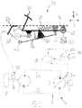
- eine erfindungsgemäße Bremspedaleinrichtung eines Flurförderzeugs in einer Neutralstellung,
- Figur 2
- die Bremspedaleinrichtung der
Figur 1 am Ende des ersten Betätigungsbereichs und - Figur 3
- die Bremspedaleinrichtung der
Figuren 1 und2 im zweiten Betätigungsbereich. - In der
Figur 1 ist ein Flurförderzeug 1 mit einem hydrostatischen Fahrantrieb 2 in einer Prinzipdarstellung dargestellt. - Der hydrostatische Fahrantrieb 2 weist eine im Fördervolumen verstellbare Verstellpumpe 3 auf, die von einem Antriebsmotor 4, beispielsweise einem Verbrennungsmotor, angetrieben ist. Mittels Druckmittelleitungen 5a, 5b ist die Verstellpumpe 3 im geschlossenen Kreislauf an einen oder mehrere hydraulische Motoren 6 angeschlossen, die über eine Abtriebswelle 7 mit einem Antriebsrad 8 des Flurförderzeugs in trieblicher Verbindung stehen.
- Die Verstellpumpe 3 weist zur Veränderung des Fördervolumens eine Fördervolumenstelleinrichtung 3a auf, beispielsweise eine in der Neigung verstellbare Schrägscheibe einer als Schrägscheibenmaschine ausgebildeten Verstellpumpe 3. Die Fördervolumenstelleinrichtung 3a ist elektrisch angesteuert und steht zur Ansteuerung mit einer elektronischen Steuereinrichtung 10 in Verbindung. Die elektronische Steuereinrichtung 10 steht eingangsseitig mit einer Fahrpedaleinrichtung 11 in Verbindung, mit der der hydrostatische Fahrantrieb 2 steuerbar ist. Die Fahrpedaleinrichtung 11 ist im dargestellten Ausführungsbeispiel als Doppelpedalsteuerung mit zwei Fahrpedalen 11a, 11b ausgeführt. Mit dem Fahrpedal 11a kann die Vorwärtsfahrt des Flurförderzeugs 1 und mit dem Fahrpedal 11b die Rückwärtsfahrt des Flurförderzeugs 1 gesteuert werden. Bei einer Betätigung des Fahrpedals 11a bzw. 11b durch die Bedienperson wird hierbei ein Geschwindigkeitssollwert für die Vorwärtsfahrt bzw. Rückwärtsfahrt vorgegeben und von der elektronischen Steuereinrichtung 10 die Fördervolumenstelleinrichtung 3a der Verstellpumpe 3 entsprechend angesteuert und die Verstellpumpe 3 ausgeschwenkt, um den an dem Fahrpedal 11a, 11b vorgegebenen Geschwindigkeitssollwert zu erzielen.
- Der hydrostatische Fahrantrieb 2 bildet weiterhin eine Betriebsbremse des Flurförderzeugs 1. Durch eine Beaufschlagung und somit eine Verstellung der Fahrpedaleinrichtung 11 in Richtung einer Neutralstellung für den Stillstand des Flurförderzeugs 1 wird hierbei von der elektronischen Steuereinrichtung 10 die Fördervolumenstelleinrichtung 3a der Verstellpumpe 3 in eine Nullstellung verstellt und zurückgeschwenkt, so dass eine hydrostatische Abbremsung des Flurförderzeugs 1 durch den hydrostatischen Fahrantrieb 2 erfolgt.
- Das Flurförderzeug 1 weist weiterhin eine Hilfsbremsanlage 15 auf, die mittels einer Bremspedaleinrichtung 20 steuerbar ist. Die Hilfsbremsanlage 15 bildet eine Feststellbremse des Flurförderzeugs 1. Die Hilfsbremsanlage 15 kann hierzu auf die Abtriebswelle 7 einwirken und als mechanische Bremseinrichtung, beispielsweise Lamellenbremse, ausgebildet sein.
- Die Bremspedaleinrichtung 20 weist ein Bremspedal 21 aufweist, das um eine Schwenkachse 22 schwenkbar am Flurförderzeug 1, beispielsweise einer Bodenplatte 1a eines Fahrerplatzes, angeordnet ist. Die Bremspedaleinrichtung 20 ist mit einer Sensoreinrichtung 23 versehen, mit der die Schwenkbewegung des Bremspedals 21 um die Schwenkachse 22 erfasst wird. Die Sensoreinrichtung 23 ist beispielswiese als Drehgeber ausgebildet. Die Sensoreinrichtung 23 steht mit der den hydrostatischen Fahrantrieb 2 steuernden elektronischen Steuereinrichtung 10 in Verbindung.
- Die Bremspedaleinrichtung 20 weist weiterhin einen Betätigungshebel 25 auf, der um eine weitere Schwenkachse 26 schwenkbar am Flurförderzeug 1, beispielsweise einer Bodenplatte 1a eines Fahrerplatzes, angeordnet ist. Mit dem Betätigungshebel 25 ist die Hilfsbremsanlage 15 betätigbar. Im dargestellten Ausführungsbeispiel ist eine mechanische Betätigung der Hilfsbremsanlage 15 vorgesehen, wobei an einem Halter 27 ein Seilzug 28, beispielsweise ein Bowdenzug, befestigt ist, der mit dem Betätigungshebel 25 an einem Koppelpunkt 29 verbunden ist.
- Die Schwenkachse 22 des Bremspedals 21 ist hierbei von der Schwenkachse 26 des Betätigungshebels 25 in vertikaler Richtung V und in horizontaler Richtung H beabstandet angeordnet.
- In der
Figur 1 befinden sich das Bremspedal 21 in seiner unbetätigten Neutralstellung und der Betätigungshebel 25 in seiner unbetätigten Neutralstellung. - Das Bremspedal 21 ist mittels einer Federeinrichtung 30 in seine Neutralstellung beaufschlagt. Die Federeinrichtung 30 ist mit einem ersten Ende mit dem Bremspedal 21 verbunden und an einem zweiten Ende mit dem Flurförderzeug 1, beispielsweise der Bodenplatte 1a, verbunden. Die Federeinrichtung 30 bildet eine Rückstellfeder des Bremspedals 21, die das Bremspedal 21 im unbetätigten Zustand in die Neutralstellung beaufschlagt.
- Der Betätigungshebel 25 ist mittels einer Federeinrichtung 31 in seine Neutralstellung beaufschlagt. Die Federeinrichtung 31 ist mit einem ersten Ende mit dem Betätigungshebel 25 verbunden und an einem zweiten Ende mit dem Flurförderzeug 1, beispielsweise der Bodenplatte 1a, verbunden.
- Zwischen dem Bremspedal 21 und dem Betätigungshebel 25 ist eine Federeinrichtung 32 angeordnet.
- An dem Bremspedal 21 ist ein Betätigungselement 35 angeordnet, mittels dem der Betätigungshebel 25 betätigbar. Das Betätigungselement 35 ist im dargestellten Ausführungsbeispiel als an dem Bremspedal 21 drehbar angeordnete Rolle 36 ausgebildet.
- In der in der
Figur 1 dargestellten Ausgangsstellung (Neutralstellung) der Bremspedaleinrichtung 20 hat der in der Neutralstellung befindliche Bremshebel 21 keinen mechanischen Kontakt mit dem in der Neutralstellung befindlichen Betätigungshebel 25. In der in derFigur 1 dargestellten Neutralstellung ist das Bremspedal 21 mit dem Betätigungselement 35 von dem Betätigungshebel 25 in vertikaler Richtung V beabstandet. - Bei einer Betätigung des Bremspedals 21 wird somit ein erster Betätigungsbereich erzielt, in dem nur das Bremspedal 21 um die Schwenkachse 22 im Gegenuhrzeigersinn verschwenkt wird, der Betätigungshebel 25 jedoch nicht betätigt wird und in seiner Neutralstellung verbleibt. In der
Figur 2 ist das Ende des ersten Betätigungsbereichs dargestellt, wobei das um die Schwenkachse 22 im Gegenuhrzeigersinn verschwenkte Bremspedals 21 mit dem Betätigungselement 35 mit dem in seiner Neutralstellung befindlichen Betätigungshebel 25 in Kontakt gelangt. - In dem ersten Betätigungsbereich wird hierbei die Federeinrichtung 32 betätigt, so dass mit der Federeinrichtung 32 eine Kraftrückmeldung an dem Bremspedal 21 im ersten Betätigungsbereich für die Bedienperson erzielt wird.
- Am Ende des ersten Betätigungsbereichs wird weiterhin mittels der Federeinrichtung 31, die den Betätigungshebel 25 in die Neutralstellung betätigt, ein Druckpunkt erzeugt, der überwunden werden muss, wenn das Bremspedal 21 weiter betätigt wird.
- Sofern das Bremspedal 21 ausgehend von der Stellung der
Figur 2 weiter betätigt wird und weiter um die Schwenkachse 22 im Gegenuhrzeigersinn verschwenkt wird, gelangt das Bremspedal 21 in einen an den ersten Schwenkbereich angrenzenden zweiten Schwenkbereich, der in derFigur 3 dargestellt ist und in dem über das Betätigungselement 35 ebenfalls der Betätigungshebel 25 betätigt und um seine Schwenkachse 26 im Gegenuhrzeigersinn verschwenkt wird. Durch das Verschwenken des Betätigungshebel 25 um seine Schwenkachse 26 im Gegenuhrzeigersinn wird der Seilzug 28 betätigt und dadurch über die Betätigung des Bremspedals 21 die Hilfsbremsanlage 15 in Richtung einer Bremsstellung betätigt. - In dem ersten Schwenkbereich des Bremspedals 21 wird mittels der Sensoreinrichtung 23 das Verschwenken des Bremspedals 21 um die Schwenkachse 22 von der elektronischen Steuereinrichtung 10 erfasst.
- Die den hydrostatischen Fahrantrieb 2 steuernde elektronische Steuereinrichtung 10 ist hierbei derart ausgebildet, dass bei einer Betätigung der den hydrostatischen Fahrantrieb 2 steuernden Fahrpedaleinrichtung 11 in Richtung einer Neutralstellung der hydroststatischen Fahrantrieb 2 derart angesteuert wird, dass das Flurförderzeug gemäß einer Minimalverzögerung abbremst. Bei einer Betätigung des Bremspedals 21 im ersten Betätigungsbereich wird von der elektronischen Steuereinrichtung 10 das Signal der Sensoreinrichtung 23 ausgewertet und die Verzögerung des Flurförderzeugs 1 durch den hydrostatischen Fahrantrieb 2 ausgehend von der Minimalverzögerung in Abhängigkeit des Signals der Sensoreinrichtung 23 erhöht. Die elektronische Steuereinrichtung 10 ist hierzu derart ausgebildet, dass mit zunehmender Betätigung des Bremspedals 21 im ersten Betätigungsbereich die hydrostatische Verzögerung des Flurförderzeugs durch den hydrostatischen Fahrantrieb 2 erhöht wird. Durch eine Betätigung des Bremspedals 21 in dem ersten Betätigungsbereich wird somit die hydrostatische Verzögerung des Flurförderzeugs 1 durch entsprechende Ansteuerung des hydrostatischen Fahrantriebs 2 ausgehend von der Minimalverzögerung bis zu einem Maximalwert am Ende des ersten Betätigungsbereichs des Bremspedals 21 erhöht.
- Am Ende des ersten Betätigungsbereichs des Bremspedals 21, wobei das Betätigungselement 35 mit dem Betätigungshebel 25 der Hilfsbremsanlage 15 in Kontakt gelangt, wird an dem Bremspedal 21 der von der Federeinrichtung 31 erzeugte Druckpunkt spürbar, der überwunden werden muss, um das Bremspedal 21 weiter in den zweiten Betätigungsbereich zu betätigen, in dem über den Betätigungshebel 25 die Hilfsbremsanlage 15 in Richtung der Bremsstellung betätigt wird.
- Bei der erfindungsgemäßen Bremspedaleinrichtung 20 ist somit der Pedalweg am Bremspedal 21 in den ersten Betätigungsbereich, in dem die hydrostatische Verzögerung des Flurförderzeugs 1 durch den hydrostatischen Fahrantrieb 2 gesteigert und erhöht wird, und in den anschließenden zweiten Betätigungsbereich aufgeteilt, in dem die Hilfsbremsanlage 15 aktiviert wird.
- In dem ersten Betätigungsbereich des Bremspedals 21 und somit der Bremspedaleinrichtung 20 ist die hydrostatische Verzögerung durch den hydrostatischen Fahrantrieb 2 verstellbar und die Hilfsbremsanlage 15 ist nicht betätigt. In dem sich an den ersten Betätigungsbereich anschließenden zweiten Betätigungsbereich des Bremspedals 21 und somit der Bremspedaleinrichtung 20 ist die Hilfsbremsanlage 15 in Richtung einer Bremsstellung betätigbar.
- Mit der erfindungsgemäßen Bremspedaleinrichtung 20 kann somit die hydrostatische Verzögerung des Flurförderzeugs durch den hydrostatischen Fahrantrieb 2 angepasst werden und verändert werden. Die hydrostatische Verzögerung, die sich bei einer Betätigung der den hydrostatischen Fahrantrieb 2 steuernden Fahrpedaleinrichtung 11 in Richtung der Neutralstellung einstellt, kann dadurch auf eine Minimalverzögerung eingestellt werden, so dass bei der Zurücknahme der Fahrpedaleinrichtung 11 in die Neutralstellung ein sanftes Abbremsen des Flurförderzeugs 1 durch den hydrostatischen Fahrantrieb erzielt wird. Für bestimmte Einsatzfälle des Flurförderzeugs 1, beispielsweise in Gießereien und beim Transport flüssiger Lasten bzw. beim Transport empfindlicher Lasten, kann somit ein sanftes Abbremsen des Flurförderzeugs 1 durch den hydrostatischen Fahrantrieb 2 bei der Zurücknahme der Fahrpedaleinrichtung 11 in die Neutralstellung erzielt werden. Durch eine zusätzliche Betätigung des Bremspedals 21 in dem ersten Betätigungsbereich kann die hydrostatische Verzögerung, mit der das Flurförderzeug 1 von dem hydrostatischen Fahrantrieb 2 abgebremst wird, angehoben und verstärkt werden, um eine stärkere Abbremsung des Flurförderzeugs 1 zu erzielen und gesetzliche Anforderungen an die Bremsverzögerung und den Bremsweg einzuhalten.
Claims (12)
- Flurförderzeug (1) mit einem hydrostatischen Fahrantrieb (2), der mittels einer Fahrpedaleinrichtung (11) steuerbar ist, wobei durch Beaufschlagen, insbesondere einer Zurücknahme, der Fahrpedaleinrichtung (11) in Richtung einer Neutralstellung eine hydrostatische Abbremsung des Flurförderzeugs (1) durch den hydrostatischen Fahrantrieb (2) erfolgt, und mit einer Hilfsbremsanlage (15), die mittels einer Bremspedaleinrichtung (20) steuerbar ist, dadurch gekennzeichnet, dass durch Betätigen der Bremspedaleinrichtung (20) die hydrostatische Verzögerung des Flurförderzeugs (1) durch den hydrostatischen Fahrantrieb (2) verstellbar ist und die Hilfsbremsanlage (15) in eine Bremsstellung betätigbar ist, wobei die Bremspedaleinrichtung (20) einen ersten Betätigungsbereich aufweist, in dem die hydrostatische Verzögerung durch den hydrostatischen Fahrantrieb (2) verstellbar ist und die Hilfsbremsanlage (15) nicht betätigt ist, und einen sich an den ersten Betätigungsbereich anschließenden zweiten Betätigungsbereich aufweist, in dem die Hilfsbremsanlage (15) in Richtung einer Bremsstellung betätigbar ist.
- Flurförderzeug nach Anspruch 1, dadurch gekennzeichnet, dass die Bremspedaleinrichtung (20) ein Bremspedal (21) aufweist, das um eine Schwenkachse (22) schwenkbar angeordnet ist, wobei eine Sensoreinrichtung (23) vorgesehen ist, die die Schwenkbewegung des Bremspedals (21) um die Schwenkachse (22) erfasst und die mit einer den hydrostatischen Fahrantrieb (2) steuernden elektronischen Steuereinrichtung (10) in Verbindung steht, und einen Betätigungshebel (25) aufweist, der um eine weitere Schwenkachse (26) schwenkbar angeordnet ist und die Hilfsbremsanlage (15) betätigt, wobei das Bremspedal (21) in dem ersten Betätigungsbereich den Betätigungshebel (25) nicht betätigt und das Bremspedal (21) in dem zweiten Betätigungsbereich den Betätigungshebel (25) betätigt.
- Flurförderzeug nach Anspruch 2, dadurch gekennzeichnet, dass das Bremspedal (21) in dem ersten Betätigungsbereich keinen mechanischen Kontakt zu dem in einer Neutralstellung befindlichen Betätigungshebel (25) aufweist und am Ende des ersten Betätigungsbereichs mit dem in der Neutralstellung befindlichem Betätigungshebel (25) in mechanischen Kontakt gelangt.
- Flurförderzeug nach Anspruch 2 oder 3, dadurch gekennzeichnet, dass das Bremspedal (21) mittels einer Federeinrichtung (30) in eine Neutralstellung beaufschlagt ist.
- Flurförderzeug nach einem der Ansprüche 2 bis 4, dadurch gekennzeichnet, dass der Betätigungshebel (25) mittels einer Federeinrichtung (31) in eine Neutralstellung beaufschlagt ist.
- Flurförderzeug nach einem der Ansprüche 2 bis 5, dadurch gekennzeichnet, dass zwischen dem Bremspedal (21) und dem Betätigungshebel (25) eine Federeinrichtung (32) angeordnet ist.
- Flurförderzeug nach einem der Ansprüche 2 bis 6, dadurch gekennzeichnet, dass an dem Bremspedal (21) ein Betätigungselement (35) angeordnet ist, mittels dem in dem zweiten Betätigungsbereich der Betätigungshebel (25) betätigbar ist.
- Flurförderzeug nach Anspruch 7, dadurch gekennzeichnet, dass das Betätigungselement (35) als an dem Bremspedal (21) drehbar angeordnete Rolle (36) ausgebildet ist.
- Flurförderzeug nach einem der Ansprüche 2 bis 8, dadurch gekennzeichnet, dass die den hydrostatischen Fahrantrieb (2) steuernde elektronische Steuereinrichtung (10) derart ausgebildet ist, dass bei einer Betätigung der den hydrostatischen Fahrantrieb (2) steuernden Fahrpedaleinrichtung (11) in Richtung einer Neutralstellung der hydroststatische Fahrantrieb (2) derart angesteuert wird, dass das Flurförderzeug (1) gemäß einer Minimalverzögerung abbremst, und bei einer Betätigung des Bremspedals (21) im ersten Betätigungsbereich die Verzögerung des Flurförderzeugs (1) durch den hydrostatischen Fahrantrieb (2) ausgehend von der Minimalverzögerung in Abhängigkeit des Signals der Sensoreinrichtung (23) erhöht wird.
- Flurförderzeug nach Anspruch 9, dadurch gekennzeichnet, dass die elektronische Steuereinrichtung (10) derart ausgebildet ist, dass mit zunehmender Betätigung des Bremspedals (21) im ersten Betätigungsbereich die Verzögerung des Flurförderzeugs (1) durch den hydrostatischen Fahrantrieb (2) erhöht wird.
- Flurförderzeug nach Anspruch 9 oder 10, dadurch gekennzeichnet, dass die Minimalverzögerung einstellbar ist.
- Flurförderzeug nach einem der Ansprüche 1 bis 11, dadurch gekennzeichnet, dass der Betätigungshebel (25) die Hilfsbremsanlage (15) mechanisch oder hydraulisch oder pneumatisch oder elektrisch betätigt.
Applications Claiming Priority (1)
| Application Number | Priority Date | Filing Date | Title |
|---|---|---|---|
| DE102019107564.5A DE102019107564A1 (de) | 2019-03-25 | 2019-03-25 | Flurförderzeug mit einem hydrostatischen Fahrantrieb |
Publications (2)
| Publication Number | Publication Date |
|---|---|
| EP3715677A1 true EP3715677A1 (de) | 2020-09-30 |
| EP3715677B1 EP3715677B1 (de) | 2021-09-08 |
Family
ID=70008239
Family Applications (1)
| Application Number | Title | Priority Date | Filing Date |
|---|---|---|---|
| EP20160865.0A Active EP3715677B1 (de) | 2019-03-25 | 2020-03-04 | Flurförderzeug mit einem hydrostatischen fahrantrieb |
Country Status (2)
| Country | Link |
|---|---|
| EP (1) | EP3715677B1 (de) |
| DE (1) | DE102019107564A1 (de) |
Citations (4)
| Publication number | Priority date | Publication date | Assignee | Title |
|---|---|---|---|---|
| DE1455555A1 (de) * | 1963-06-14 | 1968-11-21 | Lely Nv C Van Der | Steuervorrichtung fuer ein hydrostatisches Getriebe |
| US3542173A (en) * | 1967-02-24 | 1970-11-24 | Linde Ag | Controls for hydrostatic transmission and brakes |
| JP2002181191A (ja) * | 2000-12-15 | 2002-06-26 | Komatsu Ltd | 油圧駆動式車両のブレーキ装置 |
| DE102009031743A1 (de) * | 2008-07-29 | 2010-02-04 | Linde Material Handling Gmbh | Fahrbare Arbeitsmaschine mit einer Bremse mit zwei Druckräumen |
-
2019
- 2019-03-25 DE DE102019107564.5A patent/DE102019107564A1/de not_active Withdrawn
-
2020
- 2020-03-04 EP EP20160865.0A patent/EP3715677B1/de active Active
Patent Citations (4)
| Publication number | Priority date | Publication date | Assignee | Title |
|---|---|---|---|---|
| DE1455555A1 (de) * | 1963-06-14 | 1968-11-21 | Lely Nv C Van Der | Steuervorrichtung fuer ein hydrostatisches Getriebe |
| US3542173A (en) * | 1967-02-24 | 1970-11-24 | Linde Ag | Controls for hydrostatic transmission and brakes |
| JP2002181191A (ja) * | 2000-12-15 | 2002-06-26 | Komatsu Ltd | 油圧駆動式車両のブレーキ装置 |
| DE102009031743A1 (de) * | 2008-07-29 | 2010-02-04 | Linde Material Handling Gmbh | Fahrbare Arbeitsmaschine mit einer Bremse mit zwei Druckräumen |
Also Published As
| Publication number | Publication date |
|---|---|
| DE102019107564A1 (de) | 2020-10-01 |
| EP3715677B1 (de) | 2021-09-08 |
Similar Documents
| Publication | Publication Date | Title |
|---|---|---|
| EP1156943B1 (de) | Vorrichtung und verfahren zum steuern der fahrgeschwindigkeit eines kraftfahrzeuges | |
| DE69013599T2 (de) | Kraftfahrzeug-Regelsysteme. | |
| DE69908733T2 (de) | Feststellbremse in Fahrzeugen mit konventionellen Bremssystemen | |
| DE19750977B4 (de) | Bremsanlage | |
| DE3541354A1 (de) | Berganfahrhilfe fuer ein fahrzeug | |
| WO2019011538A1 (de) | Verfahren zum betreiben einer bremsanlage eines kraftfahrzeugs, sowie steuer- und/oder regeleinrichtung | |
| EP1650093B1 (de) | Integralbremse für ein Motorrad | |
| EP2664506A1 (de) | Fahrzeug mit einem hydrostatischen Fahrantrieb | |
| DE2041255A1 (de) | Bremsanlage fuer Fahrzeuge | |
| DE102011008707B4 (de) | Mobile Arbeitsmaschine, insbesondere Flurförderzeug | |
| EP3715677B1 (de) | Flurförderzeug mit einem hydrostatischen fahrantrieb | |
| EP2368778A2 (de) | Bremssteuerungssystem einer mobilen Arbeitsmaschine, insbesondere Flurförderzeug | |
| DE19920848A1 (de) | Vorrichtung zur Ansteuerung von zumindest einer elektromechanischen Betriebseinrichtung eines Kfz. | |
| DE102018112042A1 (de) | Bremssystem für ein Arbeitsfahrzeug und Verfahren dafür | |
| DE102012106212A1 (de) | Bremssteuerungssystem einer mobilen Arbeitsmaschine | |
| DE102011008708B4 (de) | Mobile Arbeitsmaschine | |
| DE102009005009A1 (de) | Fahrbare Arbeitsmaschine mit hydraulisch lösbarer Federspeicherbremse | |
| DE102019106695A1 (de) | Steuerungssystem und Verfahren zur Steuerung des Antriebs- und Bremssystems eines Kraftfahrzeugs | |
| EP3461707A1 (de) | Steuersystem einer hydraulisch betätigten bremseinrichtung | |
| DE19952781A1 (de) | Verfahren zum Abbremsen eines Fahrzeugs | |
| DE19941876C2 (de) | Arbeitsfahrzeug mit einem hydrodynamischen Fahrantrieb | |
| DE102017204461A1 (de) | Hydrostatischer Fahrantrieb | |
| WO2004015293A1 (de) | Mobiles fahrzeug mit einer reibungskupplung und einem inch-pedal | |
| DE2824448C2 (de) | ||
| EP4357207B1 (de) | Einstellverfahren von betriebsbremsfunktionen für mobile arbeitsmaschinen sowie eine bremsanordnung |
Legal Events
| Date | Code | Title | Description |
|---|---|---|---|
| PUAI | Public reference made under article 153(3) epc to a published international application that has entered the european phase |
Free format text: ORIGINAL CODE: 0009012 |
|
| STAA | Information on the status of an ep patent application or granted ep patent |
Free format text: STATUS: THE APPLICATION HAS BEEN PUBLISHED |
|
| AK | Designated contracting states |
Kind code of ref document: A1 Designated state(s): AL AT BE BG CH CY CZ DE DK EE ES FI FR GB GR HR HU IE IS IT LI LT LU LV MC MK MT NL NO PL PT RO RS SE SI SK SM TR |
|
| AX | Request for extension of the european patent |
Extension state: BA ME |
|
| STAA | Information on the status of an ep patent application or granted ep patent |
Free format text: STATUS: REQUEST FOR EXAMINATION WAS MADE |
|
| 17P | Request for examination filed |
Effective date: 20210304 |
|
| RBV | Designated contracting states (corrected) |
Designated state(s): AL AT BE BG CH CY CZ DE DK EE ES FI FR GB GR HR HU IE IS IT LI LT LU LV MC MK MT NL NO PL PT RO RS SE SI SK SM TR |
|
| GRAP | Despatch of communication of intention to grant a patent |
Free format text: ORIGINAL CODE: EPIDOSNIGR1 |
|
| STAA | Information on the status of an ep patent application or granted ep patent |
Free format text: STATUS: GRANT OF PATENT IS INTENDED |
|
| RIC1 | Information provided on ipc code assigned before grant |
Ipc: B60T 7/10 20060101ALI20210412BHEP Ipc: B60T 7/04 20060101ALI20210412BHEP Ipc: B60T 1/093 20060101ALI20210412BHEP Ipc: B60T 1/06 20060101ALI20210412BHEP Ipc: F16H 61/4157 20100101AFI20210412BHEP |
|
| INTG | Intention to grant announced |
Effective date: 20210519 |
|
| GRAS | Grant fee paid |
Free format text: ORIGINAL CODE: EPIDOSNIGR3 |
|
| GRAA | (expected) grant |
Free format text: ORIGINAL CODE: 0009210 |
|
| STAA | Information on the status of an ep patent application or granted ep patent |
Free format text: STATUS: THE PATENT HAS BEEN GRANTED |
|
| AK | Designated contracting states |
Kind code of ref document: B1 Designated state(s): AL AT BE BG CH CY CZ DE DK EE ES FI FR GB GR HR HU IE IS IT LI LT LU LV MC MK MT NL NO PL PT RO RS SE SI SK SM TR |
|
| REG | Reference to a national code |
Ref country code: GB Ref legal event code: FG4D Free format text: NOT ENGLISH |
|
| REG | Reference to a national code |
Ref country code: CH Ref legal event code: EP Ref country code: AT Ref legal event code: REF Ref document number: 1428874 Country of ref document: AT Kind code of ref document: T Effective date: 20210915 |
|
| REG | Reference to a national code |
Ref country code: DE Ref legal event code: R096 Ref document number: 502020000170 Country of ref document: DE |
|
| REG | Reference to a national code |
Ref country code: IE Ref legal event code: FG4D Free format text: LANGUAGE OF EP DOCUMENT: GERMAN |
|
| REG | Reference to a national code |
Ref country code: LT Ref legal event code: MG9D |
|
| REG | Reference to a national code |
Ref country code: NL Ref legal event code: MP Effective date: 20210908 |
|
| PG25 | Lapsed in a contracting state [announced via postgrant information from national office to epo] |
Ref country code: HR Free format text: LAPSE BECAUSE OF FAILURE TO SUBMIT A TRANSLATION OF THE DESCRIPTION OR TO PAY THE FEE WITHIN THE PRESCRIBED TIME-LIMIT Effective date: 20210908 Ref country code: FI Free format text: LAPSE BECAUSE OF FAILURE TO SUBMIT A TRANSLATION OF THE DESCRIPTION OR TO PAY THE FEE WITHIN THE PRESCRIBED TIME-LIMIT Effective date: 20210908 Ref country code: NO Free format text: LAPSE BECAUSE OF FAILURE TO SUBMIT A TRANSLATION OF THE DESCRIPTION OR TO PAY THE FEE WITHIN THE PRESCRIBED TIME-LIMIT Effective date: 20211208 Ref country code: BG Free format text: LAPSE BECAUSE OF FAILURE TO SUBMIT A TRANSLATION OF THE DESCRIPTION OR TO PAY THE FEE WITHIN THE PRESCRIBED TIME-LIMIT Effective date: 20211208 Ref country code: LT Free format text: LAPSE BECAUSE OF FAILURE TO SUBMIT A TRANSLATION OF THE DESCRIPTION OR TO PAY THE FEE WITHIN THE PRESCRIBED TIME-LIMIT Effective date: 20210908 Ref country code: SE Free format text: LAPSE BECAUSE OF FAILURE TO SUBMIT A TRANSLATION OF THE DESCRIPTION OR TO PAY THE FEE WITHIN THE PRESCRIBED TIME-LIMIT Effective date: 20210908 Ref country code: RS Free format text: LAPSE BECAUSE OF FAILURE TO SUBMIT A TRANSLATION OF THE DESCRIPTION OR TO PAY THE FEE WITHIN THE PRESCRIBED TIME-LIMIT Effective date: 20210908 Ref country code: ES Free format text: LAPSE BECAUSE OF FAILURE TO SUBMIT A TRANSLATION OF THE DESCRIPTION OR TO PAY THE FEE WITHIN THE PRESCRIBED TIME-LIMIT Effective date: 20210908 |
|
| PG25 | Lapsed in a contracting state [announced via postgrant information from national office to epo] |
Ref country code: LV Free format text: LAPSE BECAUSE OF FAILURE TO SUBMIT A TRANSLATION OF THE DESCRIPTION OR TO PAY THE FEE WITHIN THE PRESCRIBED TIME-LIMIT Effective date: 20210908 Ref country code: GR Free format text: LAPSE BECAUSE OF FAILURE TO SUBMIT A TRANSLATION OF THE DESCRIPTION OR TO PAY THE FEE WITHIN THE PRESCRIBED TIME-LIMIT Effective date: 20211209 |
|
| PG25 | Lapsed in a contracting state [announced via postgrant information from national office to epo] |
Ref country code: IS Free format text: LAPSE BECAUSE OF FAILURE TO SUBMIT A TRANSLATION OF THE DESCRIPTION OR TO PAY THE FEE WITHIN THE PRESCRIBED TIME-LIMIT Effective date: 20220108 Ref country code: SM Free format text: LAPSE BECAUSE OF FAILURE TO SUBMIT A TRANSLATION OF THE DESCRIPTION OR TO PAY THE FEE WITHIN THE PRESCRIBED TIME-LIMIT Effective date: 20210908 Ref country code: SK Free format text: LAPSE BECAUSE OF FAILURE TO SUBMIT A TRANSLATION OF THE DESCRIPTION OR TO PAY THE FEE WITHIN THE PRESCRIBED TIME-LIMIT Effective date: 20210908 Ref country code: RO Free format text: LAPSE BECAUSE OF FAILURE TO SUBMIT A TRANSLATION OF THE DESCRIPTION OR TO PAY THE FEE WITHIN THE PRESCRIBED TIME-LIMIT Effective date: 20210908 Ref country code: PT Free format text: LAPSE BECAUSE OF FAILURE TO SUBMIT A TRANSLATION OF THE DESCRIPTION OR TO PAY THE FEE WITHIN THE PRESCRIBED TIME-LIMIT Effective date: 20220110 Ref country code: PL Free format text: LAPSE BECAUSE OF FAILURE TO SUBMIT A TRANSLATION OF THE DESCRIPTION OR TO PAY THE FEE WITHIN THE PRESCRIBED TIME-LIMIT Effective date: 20210908 Ref country code: NL Free format text: LAPSE BECAUSE OF FAILURE TO SUBMIT A TRANSLATION OF THE DESCRIPTION OR TO PAY THE FEE WITHIN THE PRESCRIBED TIME-LIMIT Effective date: 20210908 Ref country code: EE Free format text: LAPSE BECAUSE OF FAILURE TO SUBMIT A TRANSLATION OF THE DESCRIPTION OR TO PAY THE FEE WITHIN THE PRESCRIBED TIME-LIMIT Effective date: 20210908 Ref country code: CZ Free format text: LAPSE BECAUSE OF FAILURE TO SUBMIT A TRANSLATION OF THE DESCRIPTION OR TO PAY THE FEE WITHIN THE PRESCRIBED TIME-LIMIT Effective date: 20210908 Ref country code: AL Free format text: LAPSE BECAUSE OF FAILURE TO SUBMIT A TRANSLATION OF THE DESCRIPTION OR TO PAY THE FEE WITHIN THE PRESCRIBED TIME-LIMIT Effective date: 20210908 |
|
| REG | Reference to a national code |
Ref country code: DE Ref legal event code: R097 Ref document number: 502020000170 Country of ref document: DE |
|
| PLBE | No opposition filed within time limit |
Free format text: ORIGINAL CODE: 0009261 |
|
| STAA | Information on the status of an ep patent application or granted ep patent |
Free format text: STATUS: NO OPPOSITION FILED WITHIN TIME LIMIT |
|
| PG25 | Lapsed in a contracting state [announced via postgrant information from national office to epo] |
Ref country code: DK Free format text: LAPSE BECAUSE OF FAILURE TO SUBMIT A TRANSLATION OF THE DESCRIPTION OR TO PAY THE FEE WITHIN THE PRESCRIBED TIME-LIMIT Effective date: 20210908 |
|
| 26N | No opposition filed |
Effective date: 20220609 |
|
| PG25 | Lapsed in a contracting state [announced via postgrant information from national office to epo] |
Ref country code: SI Free format text: LAPSE BECAUSE OF FAILURE TO SUBMIT A TRANSLATION OF THE DESCRIPTION OR TO PAY THE FEE WITHIN THE PRESCRIBED TIME-LIMIT Effective date: 20210908 |
|
| PG25 | Lapsed in a contracting state [announced via postgrant information from national office to epo] |
Ref country code: MC Free format text: LAPSE BECAUSE OF FAILURE TO SUBMIT A TRANSLATION OF THE DESCRIPTION OR TO PAY THE FEE WITHIN THE PRESCRIBED TIME-LIMIT Effective date: 20210908 |
|
| REG | Reference to a national code |
Ref country code: BE Ref legal event code: MM Effective date: 20220331 |
|
| PG25 | Lapsed in a contracting state [announced via postgrant information from national office to epo] |
Ref country code: LU Free format text: LAPSE BECAUSE OF NON-PAYMENT OF DUE FEES Effective date: 20220304 Ref country code: IT Free format text: LAPSE BECAUSE OF FAILURE TO SUBMIT A TRANSLATION OF THE DESCRIPTION OR TO PAY THE FEE WITHIN THE PRESCRIBED TIME-LIMIT Effective date: 20210908 Ref country code: IE Free format text: LAPSE BECAUSE OF NON-PAYMENT OF DUE FEES Effective date: 20220304 |
|
| PG25 | Lapsed in a contracting state [announced via postgrant information from national office to epo] |
Ref country code: BE Free format text: LAPSE BECAUSE OF NON-PAYMENT OF DUE FEES Effective date: 20220331 |
|
| P01 | Opt-out of the competence of the unified patent court (upc) registered |
Effective date: 20230507 |
|
| REG | Reference to a national code |
Ref country code: CH Ref legal event code: PL |
|
| PG25 | Lapsed in a contracting state [announced via postgrant information from national office to epo] |
Ref country code: LI Free format text: LAPSE BECAUSE OF NON-PAYMENT OF DUE FEES Effective date: 20230331 Ref country code: CH Free format text: LAPSE BECAUSE OF NON-PAYMENT OF DUE FEES Effective date: 20230331 |
|
| PG25 | Lapsed in a contracting state [announced via postgrant information from national office to epo] |
Ref country code: MK Free format text: LAPSE BECAUSE OF FAILURE TO SUBMIT A TRANSLATION OF THE DESCRIPTION OR TO PAY THE FEE WITHIN THE PRESCRIBED TIME-LIMIT Effective date: 20210908 Ref country code: CY Free format text: LAPSE BECAUSE OF FAILURE TO SUBMIT A TRANSLATION OF THE DESCRIPTION OR TO PAY THE FEE WITHIN THE PRESCRIBED TIME-LIMIT Effective date: 20210908 |
|
| PG25 | Lapsed in a contracting state [announced via postgrant information from national office to epo] |
Ref country code: HU Free format text: LAPSE BECAUSE OF FAILURE TO SUBMIT A TRANSLATION OF THE DESCRIPTION OR TO PAY THE FEE WITHIN THE PRESCRIBED TIME-LIMIT; INVALID AB INITIO Effective date: 20200304 |
|
| PG25 | Lapsed in a contracting state [announced via postgrant information from national office to epo] |
Ref country code: TR Free format text: LAPSE BECAUSE OF FAILURE TO SUBMIT A TRANSLATION OF THE DESCRIPTION OR TO PAY THE FEE WITHIN THE PRESCRIBED TIME-LIMIT Effective date: 20210908 |
|
| PG25 | Lapsed in a contracting state [announced via postgrant information from national office to epo] |
Ref country code: MT Free format text: LAPSE BECAUSE OF FAILURE TO SUBMIT A TRANSLATION OF THE DESCRIPTION OR TO PAY THE FEE WITHIN THE PRESCRIBED TIME-LIMIT Effective date: 20210908 |
|
| PGFP | Annual fee paid to national office [announced via postgrant information from national office to epo] |
Ref country code: AT Payment date: 20250417 Year of fee payment: 5 |
|
| PGFP | Annual fee paid to national office [announced via postgrant information from national office to epo] |
Ref country code: GB Payment date: 20260324 Year of fee payment: 7 |
|
| PGFP | Annual fee paid to national office [announced via postgrant information from national office to epo] |
Ref country code: DE Payment date: 20260320 Year of fee payment: 7 |
|
| PGFP | Annual fee paid to national office [announced via postgrant information from national office to epo] |
Ref country code: FR Payment date: 20260324 Year of fee payment: 7 |