EP3715201B1 - Aktuatoranordnung mit integriertem gehäuse für eine elektromechanische feststellbremse - Google Patents
Aktuatoranordnung mit integriertem gehäuse für eine elektromechanische feststellbremse Download PDFInfo
- Publication number
- EP3715201B1 EP3715201B1 EP19165465.6A EP19165465A EP3715201B1 EP 3715201 B1 EP3715201 B1 EP 3715201B1 EP 19165465 A EP19165465 A EP 19165465A EP 3715201 B1 EP3715201 B1 EP 3715201B1
- Authority
- EP
- European Patent Office
- Prior art keywords
- assembly
- gear
- motor
- seat
- permanent magnets
- Prior art date
- Legal status (The legal status is an assumption and is not a legal conclusion. Google has not performed a legal analysis and makes no representation as to the accuracy of the status listed.)
- Active
Links
- 238000009434 installation Methods 0.000 claims description 35
- 238000001746 injection moulding Methods 0.000 claims description 29
- 238000000465 moulding Methods 0.000 claims description 20
- 230000009467 reduction Effects 0.000 claims description 7
- 230000007423 decrease Effects 0.000 claims description 2
- 238000000034 method Methods 0.000 description 11
- 230000008569 process Effects 0.000 description 9
- 238000004519 manufacturing process Methods 0.000 description 4
- 230000003014 reinforcing effect Effects 0.000 description 3
- 230000005540 biological transmission Effects 0.000 description 2
- 230000006866 deterioration Effects 0.000 description 2
- 239000000463 material Substances 0.000 description 2
- 238000005452 bending Methods 0.000 description 1
- 239000003638 chemical reducing agent Substances 0.000 description 1
- 239000002131 composite material Substances 0.000 description 1
- 230000008878 coupling Effects 0.000 description 1
- 238000010168 coupling process Methods 0.000 description 1
- 238000005859 coupling reaction Methods 0.000 description 1
- 238000005520 cutting process Methods 0.000 description 1
- 230000001419 dependent effect Effects 0.000 description 1
- 230000000694 effects Effects 0.000 description 1
- 238000005516 engineering process Methods 0.000 description 1
- 230000002452 interceptive effect Effects 0.000 description 1
- 239000002184 metal Substances 0.000 description 1
- 238000003825 pressing Methods 0.000 description 1
- 239000002990 reinforced plastic Substances 0.000 description 1
- 229920003002 synthetic resin Polymers 0.000 description 1
- 239000000057 synthetic resin Substances 0.000 description 1
- 238000003466 welding Methods 0.000 description 1
Images


Classifications
-
- B—PERFORMING OPERATIONS; TRANSPORTING
- B60—VEHICLES IN GENERAL
- B60T—VEHICLE BRAKE CONTROL SYSTEMS OR PARTS THEREOF; BRAKE CONTROL SYSTEMS OR PARTS THEREOF, IN GENERAL; ARRANGEMENT OF BRAKING ELEMENTS ON VEHICLES IN GENERAL; PORTABLE DEVICES FOR PREVENTING UNWANTED MOVEMENT OF VEHICLES; VEHICLE MODIFICATIONS TO FACILITATE COOLING OF BRAKES
- B60T13/00—Transmitting braking action from initiating means to ultimate brake actuator with power assistance or drive; Brake systems incorporating such transmitting means, e.g. air-pressure brake systems
- B60T13/74—Transmitting braking action from initiating means to ultimate brake actuator with power assistance or drive; Brake systems incorporating such transmitting means, e.g. air-pressure brake systems with electrical assistance or drive
- B60T13/741—Transmitting braking action from initiating means to ultimate brake actuator with power assistance or drive; Brake systems incorporating such transmitting means, e.g. air-pressure brake systems with electrical assistance or drive acting on an ultimate actuator
-
- H—ELECTRICITY
- H02—GENERATION; CONVERSION OR DISTRIBUTION OF ELECTRIC POWER
- H02K—DYNAMO-ELECTRIC MACHINES
- H02K7/00—Arrangements for handling mechanical energy structurally associated with dynamo-electric machines, e.g. structural association with mechanical driving motors or auxiliary dynamo-electric machines
- H02K7/10—Structural association with clutches, brakes, gears, pulleys or mechanical starters
- H02K7/116—Structural association with clutches, brakes, gears, pulleys or mechanical starters with gears
-
- F—MECHANICAL ENGINEERING; LIGHTING; HEATING; WEAPONS; BLASTING
- F16—ENGINEERING ELEMENTS AND UNITS; GENERAL MEASURES FOR PRODUCING AND MAINTAINING EFFECTIVE FUNCTIONING OF MACHINES OR INSTALLATIONS; THERMAL INSULATION IN GENERAL
- F16D—COUPLINGS FOR TRANSMITTING ROTATION; CLUTCHES; BRAKES
- F16D2121/00—Type of actuator operation force
- F16D2121/18—Electric or magnetic
- F16D2121/24—Electric or magnetic using motors
-
- F—MECHANICAL ENGINEERING; LIGHTING; HEATING; WEAPONS; BLASTING
- F16—ENGINEERING ELEMENTS AND UNITS; GENERAL MEASURES FOR PRODUCING AND MAINTAINING EFFECTIVE FUNCTIONING OF MACHINES OR INSTALLATIONS; THERMAL INSULATION IN GENERAL
- F16D—COUPLINGS FOR TRANSMITTING ROTATION; CLUTCHES; BRAKES
- F16D2125/00—Components of actuators
- F16D2125/18—Mechanical mechanisms
- F16D2125/44—Mechanical mechanisms transmitting rotation
- F16D2125/46—Rotating members in mutual engagement
- F16D2125/50—Rotating members in mutual engagement with parallel non-stationary axes, e.g. planetary gearing
-
- F—MECHANICAL ENGINEERING; LIGHTING; HEATING; WEAPONS; BLASTING
- F16—ENGINEERING ELEMENTS AND UNITS; GENERAL MEASURES FOR PRODUCING AND MAINTAINING EFFECTIVE FUNCTIONING OF MACHINES OR INSTALLATIONS; THERMAL INSULATION IN GENERAL
- F16H—GEARING
- F16H55/00—Elements with teeth or friction surfaces for conveying motion; Worms, pulleys or sheaves for gearing mechanisms
- F16H55/02—Toothed members; Worms
- F16H55/17—Toothed wheels
- F16H2055/176—Ring gears with inner teeth
-
- F—MECHANICAL ENGINEERING; LIGHTING; HEATING; WEAPONS; BLASTING
- F16—ENGINEERING ELEMENTS AND UNITS; GENERAL MEASURES FOR PRODUCING AND MAINTAINING EFFECTIVE FUNCTIONING OF MACHINES OR INSTALLATIONS; THERMAL INSULATION IN GENERAL
- F16H—GEARING
- F16H57/00—General details of gearing
- F16H57/02—Gearboxes; Mounting gearing therein
- F16H2057/02034—Gearboxes combined or connected with electric machines
-
- F—MECHANICAL ENGINEERING; LIGHTING; HEATING; WEAPONS; BLASTING
- F16—ENGINEERING ELEMENTS AND UNITS; GENERAL MEASURES FOR PRODUCING AND MAINTAINING EFFECTIVE FUNCTIONING OF MACHINES OR INSTALLATIONS; THERMAL INSULATION IN GENERAL
- F16H—GEARING
- F16H37/00—Combinations of mechanical gearings, not provided for in groups F16H1/00 - F16H35/00
- F16H37/02—Combinations of mechanical gearings, not provided for in groups F16H1/00 - F16H35/00 comprising essentially only toothed or friction gearings
- F16H37/04—Combinations of toothed gearings only
- F16H37/041—Combinations of toothed gearings only for conveying rotary motion with constant gear ratio
Definitions
- the present invention relates to an actuator assembly for operating an electromechanical parking brake and, more particularly, to an actuator assembly for an electromechanical parking brake in which a stator and a ring gear are integrated with a housing.
- An actuator for an automotive electromechanical parking brake is an apparatus for operating friction pads disposed on a caliper of a disc brake system for parking.
- the actuator is automatically operated when a user operates a switch for an electromechanical parking brake, and for this purpose, the actuator includes an electromechanical parking brake motor and a gear assembly (power transmission device) for transmitting power from the motor.
- Such an actuator is composed of several rotary parts and the rotary parts are rotated in mesh with each other, so tolerance management is important.
- tolerance management is important.
- problems with quality such as performance deterioration or noise may be generated.
- vibration of a motor that is generated in operation causes shaking of the parts including gears and deteriorates durability of the gears due to the accumulated tolerance, thereby reducing durability of the resultant product.
- an actuator technology including a case, a electric motor, a magnet and gears is disclosed in Japanese Patent Application Publication No. JP 2018 185053 A .
- the present invention has been made in an effort to solve the problems in the related art and an object of the present invention is to improve convenience of assembly and inter-shaft alignment by integrating a stator of a motor assembly and a ring gear of a gear assembly with one housing in an actuator assembly including the motor and the gear assembly.
- an aspect of the present invention provides an actuator assembly with an integrated housing for an electromechanical parking brake according to claim 1 is provided. Further embodiments are described in the dependent claims.
- the actuator assembly includes: a main housing having an integrated motor seat and an integrated gear set; a motor assembly disposed in the motor seat and providing torque; a gear assembly rotated by the torque from the motor assembly and performing a reduction function through a plurality of gears; a stator part constituting the motor assembly and at least partially formed on the inner side of the motor seat by insert injection molding; and a ring gear integrally formed with the gear seat or formed by insert injection molding and operating the gear assembly.
- the stator part may include: a plurality of permanent magnets; and a yoke surrounding the permanent magnets, and the permanent magnets and the yoke may be at least partially integrated by insert injection molding when the main housing is molded.
- the stator part may be formed by insert injection molding such that outer sides of the permanent magnets are not exposed, or an upper portion and a lower portion of the stator part may be formed by insert injection molding such that the outer sides of the permanent magnets are at least partially exposed.
- the ring gear may be formed integrally around an inner side of the gear seat or may be separately manufactured and then integrated by insert injection molding when the main housing is molded, and planetary gears constituting the gear assembly may revolve in contact with an inner side of the ring gear.
- the ring gear may be manufactured with relatively higher strength than the main housing and then integrated with the gear seat by insert injection molding.
- a bearing supporting a lower portion of a motor shaft of the motor assembly may be integrally formed with the motor seat together with the stator part by insert injection molding.
- the main housing may include: a frame part extending left and right; the motor seat formed at a side of the frame part and having the motor assembly in a first installation space defined therein; and the gear seat formed at another side of the frame part, opposite the motor seat, extending in parallel with the motor seat, and having the gear assembly in a second installation space defined therein.
- An installation fence may protrude along an edge of the frame part and an idle gear connecting the motor assembly and the gear assembly to each other may be disposed in a space surrounded by the installation fence.
- the actuator assembly with an integrated housing for an electromechanical parking brake according to the present invention has the following effects.
- the motor assembly, the stator part, and the ring gear of the gear assembly are integrally formed with one main housing in the actuator assembly. Accordingly, several parts are aligned in one main housing, so inter-shaft alignment of the motor and the gears is improved and accordingly performance of a product is improved.
- stator part of the motor assembly is integrally formed with the main housing by insert injection molding and a gear box that was separately configured in the relate art is installed in the main housing, the assembly processes are reduced and a tolerance is more easily managed.
- the ring gear constituting the gear assembly is integrally formed with the gear assembly or integrated in the main housing by insert injection molding in the present invention, so it is possible to prevent torque that is provided through a resultant output shaft from shaking or from generating noise due to a tolerance issue.
- an installation fence protrudes from the main housing and an idle gear connecting the motor assembly and the gear assembly to each other is disposed in a space surrounded by the installation fence. Accordingly, all driving parts are disposed in the main housing in the present invention, so it is possible to manage an assembly tolerance through designing/producing of the main housing, so efficiency of management can be improved.
- An actuator assembly with an integrated housing for an electromechanical parking brake (hereafter, referred to as an 'actuator assembly') according to the present invention generates large torque by reducing rotation of a motor and transmits the torque to the outside to achieve the function of an electromechanical parking brake.
- a motor and a gear assembly are disposed in the actuator assembly of the present invention.
- the internal parts are largely classified into a motor assembly and a gear assembly for the convenience of description to be given hereafter.
- the entire outer structure of an actuator assembly is formed by combining a main housing 10 and a cover 38.
- a closed installation space is defined therein and several parts are disposed in the installation space to operate the actuator assembly.
- the main housing 10 and the cover 18 are combined, as shown in the figure, only a connector socket 13 and an end of a resultant output shaft are exposed without the other parts exposed out of the installation space 15.
- a relative connector is inserted in a coupling space of the connector socket 13.
- the main housing 10 has a motor assembly and a gear assembly therein.
- the motor assembly and the gear assembly are spaced apart from each other and respectively have rotary shafts that are parallel with each other.
- the main housing 10 is a single unit and is made of synthetic resin through injection molding in this embodiment.
- the main housing 10 can be largely divided into three parts, which are a frame part 11, a motor seat 21 and the gear seat 31.
- the frame part 11, which is a part forming the fundamental structure, has a plate shape extending left and right in FIG. 3 , and the motor seat 21 and the gear seat 31 are disposed respectively at both sides of the frame part 11.
- the connector socket 13 described above is formed close to the motor seat 21 and terminals T1 disposed in the connector socket 13 may be electrically connected in contact with motor terminals T2 of a brush card assembly 27 to be described below.
- the frame part 11 has an installation fence 15.
- the installation fence 15 is a portion protruding upward along the edge of the frame part 11 and a predetermined space is defined at the inside surrounded by the installation fence 15.
- An idle gear 45, a pinion gear 40 disposed at the upper portion of the motor assembly, and a drive gear 50 of the gear assembly are disposed in the space, which will be described below.
- the cover 38 is coupled to the outer side of the installation fence 15.
- Reference numeral '16' indicates a gear groove, and a rotary shaft 46 of the idle gear 45 is inserted in the gear groove 16.
- the frame part 11 has a plurality of reinforcing ribs 17.
- the reinforcing ribs 17 increase the entire strength of the frame part 11, thereby being able to prevent the entire main housing 10 including the frame part 11 from deforming such as bending.
- the reinforcing ribs 17 are formed only at the center portion of the frame part 11, but they are not limited thereto and may exist throughout the frame part 11.
- Reference numeral '19' indicates holes in which bolts B that are fasteners are fastened.
- the brush card assembly 27 can be fixed to the main housing 10.
- a guide hole 19' is formed close to the fastening grooves 19 at the frame part 11.
- the guide hole 19' is a hole extending up and down in the installation direction of the brush card assembly 27 and a guide pin P of the brush card assembly 27 is fitted in the guide hole.
- the brush card assembly 17 can be accurately guided in the installation direction. That is, when the guide pin P is fitted in the guide hole 19' even before the bolts B are fastened in the fastening groove 19, the brush card assembly 27 can be accurately guided in the installation direction.
- the guide pin P may be formed integrally with the brush card assembly 27 or may be separately manufactured and then combined with the brush card assembly 27.
- a motor assembly 21 is disposed on the frame part 11.
- the motor seat 21 is a part extending perpendicular to the frame part 11 and the motor assembly is disposed in the motor seat 21.
- the motor seat 21 has a first installation space 22 extending up and down therein and the first installation space 22 has a substantially cylindrical shape.
- a stator part 24 and 25 is disposed in the first installation space 22 and the motor assembly is disposed at the center.
- the motor seat 21 has an open top and the motor assembly can be installed through the open top.
- the stator part 24 and 25 is disposed in the first installation space 22 of the motor seat 21.
- the stator part 24 and 25 provides magnetic force for rotating an armature core 26 to be described below.
- the stator part 24 and 25 is disposed on the inner side of the first installation space 22 and is composed of a permanent magnet 25 and a yoke 24.
- a plurality of permanent magnets 25 is provided and the yoke 24 may be a cylinder surrounding the permanent magnets 25.
- the permanent magnets 25 may be fixed to the yoke 24 by bonding.
- the stator part 24 and 25 is formed in the motor seat 21 by insert injection molding.
- the stator part 24 and 25 is integrally formed at the portion that becomes the motor seat 21 when the main housing 10 including the motor seat 21 is formed by injection molding. Accordingly, the stator part 24 and 25 is combined with the motor seat 21 not to be separated, and for reference, the stator part 24 and 25 shown separately in FIG. 3 is only to help understanding.
- the stator part 24 and 25 is at least partially fixed to the motor seat 21 by insert injection molding that is a different-material composite forming technique.
- the permanent magnets 25 and the yoke 24 of the stator part 24 and 25 are integrated with the motor seat 21, in which the motor seat 21 may be configured to fully cover the permanent magnets 25 up to the fronts of the permanent magnets 25 or may be formed to cover only portions of the permanent magnets 25.
- the upper portion and lower portion of the stator part 24 and 25 may be fixed by injection molding with the motor seat 21.
- a reference numeral '23' indicates a portion that covers the stator part 24 and 25 in insert injection molding and the portion becomes an over-molding portion when molding is finished.
- the stator part 24 and 25 is installed in the motor seat 21.
- the yoke 24 of the stator part 24 and 25 is disposed and completely covered by the over-molding portion 23 of the motor seat 21, but the permanents magnets 25 are partially exposed. More accurately, both edges of the permanent magnets 25 are embedded in the over-molding portion 23 in the motor seat 21, but the center portions of the permanent magnets 25 are exposed. Accordingly, the magnetic force of the permanent magnets 25 can be sufficiently transmitted to the armature core 26. That is, the permanent magnets 25 are firmly fixed by the over-molding portion 23, but deterioration of the function of the permanent magnets 25 can be prevented by the over-molding portion 23.
- the stator part 24 and 25 is shown well in FIG. 6 .
- inclined portions 25' are formed at both side ends of the permanent magnets 25 of the stator part 24 and 25 and each have a shape recessed such that the width decreases toward the yoke 24.
- the inclined portions 25' are portions covered with the over-molding portion 23, so the permanent magnets 25 can be firmly fixed.
- the center portions A1 of the permanent magnets 25 are portions that are exposed without being covered by the over-molding portion 23 and built-in portions A1 at both sides are portions that are covered and embedded by the over-molding portion 23.
- the inclined portions 25' of the permanent magnets 25 described above are portions of the built-in portions A2, so they are portions that are covered by the over-molding portion 23.
- stator part 24 and 25 is formed when the motor seat 21 is formed by molding, there is no separate assembly process for the stator part 24 and 25 and an assembly error that may be generated in an assembly process can be reduced.
- a bearing that supports a motor shaft 26' that is the rotational center of the motor may also be formed at the motor seat 21 by insert injection molding. The bearing is disposed at the lower end of the motor shaft 26'.
- the armature core 26 and the motor shaft 26' of the motor assembly are inserted in the first installation space 22.
- the armature core 26 constitutes the motor assembly together with the stator part 24 and 25 and a coil is wound around the armature core 26. Power is applied to the coil through the brush card assembly 27 and a rectifier (not shown) changes the direction of a current flowing through the coil.
- the armature core 26 is 3-dimensinally formed by stacking a plurality of core plates and has a substantially cylindrical shape.
- the brush card assembly 27 is disposed over the first installation space 22. An end of the motor shaft 26' is exposed upward through a through-hole 27' of the brush card assembly 27 and the pinion gear 40 is coupled to the exposed portion, thereby transmitting torque to the gear assembly.
- the brush card assembly 27 has the motor terminals T2. External power can be supplied through the motor terminal T2.
- the motor terminals T2 are connected to the terminals T1 of the connector socket 13, so when a current is applied through the relative connector from the outside, the motor assembly is operated and the motor shaft 26' is rotated.
- a yoke cover 29 is disposed under the first installation space 22, thereby covering the lower portion.
- the pinion gear 40 is connected to the motor shaft 26'.
- the pinion gear 40 transmits driving force from the motor to the gear assembly while rotating with the motor shaft 26'.
- the idle gear 45 is disposed between the pinion gear 40 and the gear assembly, so primary reduction is performed.
- the idle gear 45 and the drive gear 50 of the gear assembly are engaged with each other, so the pinion gear 40 and the drive gear 50 rotate in the same direction. As described above, the idle gear 45 is rotated with the rotary shaft thereof inserted in the gear groove 16 of the frame part 11.
- the main housing 10 has the gear seat 31.
- the gear seat 31 is a part where the gear assembly is assembled, and is spaced apart from the motor seat 21.
- the gear seat 31 has a second installation space 31' and a plurality of gears constituting the gear assembly is installed in the second installation space 31'.
- a hole is formed through the bottom of the gear seat 31, so a resultant output shaft 70 can protrude through the hole.
- a fastening flange 32 is formed on a side of the gear seat 31.
- the fastening flange 32 is a portion for mounting the actuator assembly of the present invention in a vehicle and has a through-hole at the center.
- a fastener (not shown) such as a bolt is disposed through the fastening hole of the fastening flange 32.
- a plurality of fastening flanges 32 may be provided.
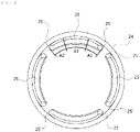
- a ring gear 35 is disposed on the inner side of the second installation space 31' of the gear seat 31.
- the ring gear 35 which revolves first planetary gears 63 and second planetary gears 67 of a planetary gear assembly 60 to be described below, is formed integrally with the gear seat 31 or is formed by insert injection molding.
- the ring gear 35 is integrally formed around the inner side of the gear seat 31 in this embodiment, it may be manufactured separately and then integrated with the main housing 10 by insert injection molding when the main housing 10 is formed by molding.
- the space surrounded by the ring gear 35 is the second installation space 31'.
- the ring gear 35 may be manufactured separately with strength relatively higher than the main housing 10 and then integrated with the gear seat 31 by insert injection molding.
- the ring gear 35 may be made of a material having high strength such as metal or reinforced plastic.
- the gear assembly 31 is assembled in the gear seat 31.
- the gear assembly is formed by combining a plurality of gears and may be considered as being largely composed of the drive gear 50 and the planetary gear assembly 60.
- the planetary gear assembly 60 includes a first carrier 61 and a second carrier 65, a plurality of first planetary gears 63 is disposed on the first carrier 61, and a plurality of second planetary gears 67 is disposed on the second carrier 65.
- the drive gear 50 that transmits torque from the gears is disposed over them and rotated in mesh with the idle gear 45.
- the first carrier 61 and the first planetary gears 63 perform secondary reduction and the second carrier 65 and the second planetary gears 67 disposed under the first carrier and first planetary gear perform third reduction. Power is output to the outside through the resultant rotary shaft 70 connected to the second carrier 65.
- the planetary gear assembly 60 is disposed and rotated in the second installation space 31' that is an internal space surrounded by the ring gear 35, and the first planetary gears 63 are rotatably coupled to the first carrier 61.
- a total of four first planetary gears 63 may be provided and they can independently rotate.
- the second carrier 65 and the second planetary gears 67 have the same configuration as the first carrier 61 and the first planetary gears 63 and are disposed under them.
- a center pin 68 is disposed at the center of the first carrier 61 as the rotational center of the first carrier 61.
- the center pin 68 is partially exposed upward through a center hole of the drive gear 50. Accordingly, the center pin 68 also functions as a rotary shaft of the drive gear 50.
- the first planetary gears 63 are rotated in mesh with each other around a sun gear (not shown) of the drive gear 50.
- the sun gear protrudes downward from the drive gear 50, is integrated with the drive gear 50, and rotates with the drive gear 50.
- the first planetary gears 63 rotating with the sun gear not only can rotate at the position, but can revolve in mesh with the ring gear 35 disposed outside them.
- the first planetary gears 63 which revolve as described above, rotate the first carrier 61, so the resultant output shaft 70 under the first carrier 61 rotates. Since the second carrier 65 and the second planetary gears 67 have the same structure, they perform reduction while rotating together.
- the gear assembly is not necessarily limited to this structure.
- the gear assembly may include only the first carrier 61 and the first planetary gears 63 without the second carrier 65 and the second planetary gears 67.
- the main housing 10 is formed by molding, and in this process, the stator part 24 and 25 is also formed by injection molding.
- the stator part 24 and 25 is molded with the main housing 10 with the permanent magnets 25 bonded to the yoke 24, and is fixed by over-molding when the motor seat 21 of the main housing 10 is molded. Accordingly, there is no need for a worker to assemble the stator parts 24 and 25 through a post-process and the stator part 24 and 25 is firmly fixed to the motor seat 21 by the over-molding portion 23, so an assembly error can be considerably reduced.
- the ring gear 35 is also integrally formed when the main housing 10 is molded.
- the ring gear 35 is formed integrally around the inner side of the gear seat 31.
- the ring gear 35 may be separately manufactured and then integrated by inserting injection molding when the main housing 10 is molded.
- the main housing 10 is a single part but may include both of the motor seat 21 and the gear seat 31 and the ring gear 35 and the stator part 24 and 25 are integrally formed in the manufacturing process, so the number of processes can be remarkably reduced and a tolerance is more easily managed.
- the motor assembly and the gear assembly are installed in the main housing 10.
- the armature core 26 of the motor assembly is put into the first installation space 22 and then the brush card assembly 27 is assembled over the armature core 26.
- the pinion gear 40 is coupled to the upper end of the motor shaft 26' of the motor assembly. It may also be formed to electrically connect the motor terminals T2 of the brush card assembly 27 and the terminals T1 of the connector socket 13 through welding.
- the gear assembly is put into the second installation space 31' and the idle gear 45 is installed between the pinion gear 40 and the drive gear 50. Finally, the cover 30 is combined with the main housing 10, thereby finishing assembly. As described above, several parts are aligned in one main housing 10, so axial alignment of a motor and gears can be improved.
Claims (10)
- Aktorbaugruppe mit einem integrierten Gehäuse für eine elektromechanische Feststellbremse, wobei die Aktorbaugruppe aufweist:ein Hauptgehäuse (10), das einen integrierten Motorsitz (21) und einen integrierten Getriebesitz (31) aufweist,eine Motorbaugruppe, die in dem Motorsitz (21) angeordnet ist und ein Drehmoment bereitstellt,eine Getriebebaugruppe, die durch das Drehmoment von der Motorbaugruppe gedreht wird und über eine Mehrzahl von Zahnrädern eine Untersetzungsfunktion ausführt,einen Statorteil (24, 25), der die Motorbaugruppe bildet und zumindest teilweise an der Innenseite des Motorsitzes (21) durch Einsatzspritzgießen ausgebildet ist, undeinen Zahnkranz, der einstückig mit dem Getriebesitz ausgebildet ist oder durch Einsatzspritzgießen ausgebildet ist und die Getriebebaugruppe betreibt,wobei der Statorteil (24, 25) aufweist:eine Mehrzahl von Dauermagneten (25) undein Joch (24), welches die Dauermagnete (25) umgibt,wobei die Dauermagnete (25) und das Joch (24) die gleiche Länge haben, undwobei die oberen Abschnitte und die unteren Abschnitte der Dauermagneten (25) und des Jochs (24) durch Einsatzspritzgießen ausgebildet werden, wenn das Hauptgehäuse (10) geformt wird, und die Dauermagneten (25) und das Joch (24) durch einen Überformungsabschnitt befestigt werden.
- Aktorbaugruppe gemäß Anspruch 1, wobei der Statorteil (24, 25) durch Einsatzspritzgießen so geformt ist, dass die Außenseiten der Dauermagnete (25) nicht freiliegen, oder ein oberer Abschnitt und ein unterer Abschnitt des Statorteils (24, 25) durch Einsatzspritzgießen so geformt sind, dass die Außenseiten der Dauermagnete (25) zumindest teilweise freiliegen.
- Aktorbaugruppe gemäß Anspruch 1 oder 2, wobei der Zahnkranz (35) einstückig um eine Innenseite des Zahnradsitzes (31) geformt ist oder separat hergestellt und dann durch Einsatzspritzgießen integriert wird, wenn das Hauptgehäuse (10) geformt wird, und Planetenräder (63, 67), die die Getriebebaugruppe bilden, sich in Kontakt mit einer Innenseite des Zahnkranzes (35) drehen.
- Aktorbaugruppe gemäß Anspruch 3, wobei der Zahnkranz (35) mit einer relativ höheren Festigkeit als das Hauptgehäuse hergestellt und dann mit dem Zahnradsitz (31) durch Einsatzspritzgießen integriert wird.
- Aktorbaugruppe gemäß Anspruch 1, wobei ein Lager, das einen unteren Abschnitt einer Motorwelle (26') der Motorbaugruppe abstützt, zusammen mit dem Statorteil (24, 25) durch Einsatzspritzgießen einstückig mit dem Motorsitz (21) ausgebildet ist.
- Aktorbaugruppe gemäß Anspruch 1, wobei das Hauptgehäuse (10) aufweist:einen Rahmenteil (11), der sich links und rechts erstreckt,den Motorsitz (21), der an einer Seite des Rahmenteils (11) ausgebildet ist und die Motorbaugruppe in einem ersten Installationsraum (22) aufweist, der darin definiert ist, undden Getriebesitz (31), der an einer anderen Seite des Rahmenteils (11) gegenüber dem Motorsitz ausgebildet ist, sich parallel zum Motorsitz erstreckt und die Getriebebaugruppe in einem zweiten Installationsraum (31') aufweist, der darin definiert ist.
- Aktorbaugruppe gemäß Anspruch 6, wobei eine Installationsumzäunung (15) entlang eines Randes des Rahmenteils (11) hervorsteht und ein Leerlaufzahnrad (45), das die Motorbaugruppe und die Getriebebaugruppe miteinander verbindet, in einem von der Installationsumzäunung (15) umgebenen Raum angeordnet ist.
- Aktorbaugruppe gemäß Anspruch 6, wobei ein Führungsloch (19') am Rahmenteil (11) ausgebildet ist und ein Führungsstift (P) einer Bürstenkartenbaugruppe (27) in das Führungsloch eingesetzt ist, so dass eine Montageposition der Bürstenkartenbaugruppe (27) eingestellt werden kann.
- Aktorbaugruppe gemäß Anspruch 1, wobei Abschnitte beider Seiten von Dauermagneten (25), die den Statorteil (24, 25) bilden, durch einen Überformungsabschnitt in den Motorsitz (21) eingebettet sind und Abschnitte von Mitten der Dauermagnete (25) außerhalb des Überformungsabschnitts des Motorsitzes (21) freiliegen, um einem Ankerkern (26) zugewandt zu sein.
- Aktorbaugruppe gemäß Anspruch 9, wobei Neigungsabschnitte, von denen eine Breite in Richtung zu einem Joch (24), das den Statorteil (24, 25) bildet, abnimmt, an beiden Rändern der Dauermagnete (25) ausgebildet und in den Motorsitz (21) eingebettet sind.
Priority Applications (1)
| Application Number | Priority Date | Filing Date | Title |
|---|---|---|---|
| EP19165465.6A EP3715201B1 (de) | 2019-03-27 | 2019-03-27 | Aktuatoranordnung mit integriertem gehäuse für eine elektromechanische feststellbremse |
Applications Claiming Priority (1)
| Application Number | Priority Date | Filing Date | Title |
|---|---|---|---|
| EP19165465.6A EP3715201B1 (de) | 2019-03-27 | 2019-03-27 | Aktuatoranordnung mit integriertem gehäuse für eine elektromechanische feststellbremse |
Publications (2)
| Publication Number | Publication Date |
|---|---|
| EP3715201A1 EP3715201A1 (de) | 2020-09-30 |
| EP3715201B1 true EP3715201B1 (de) | 2022-04-06 |
Family
ID=66041129
Family Applications (1)
| Application Number | Title | Priority Date | Filing Date |
|---|---|---|---|
| EP19165465.6A Active EP3715201B1 (de) | 2019-03-27 | 2019-03-27 | Aktuatoranordnung mit integriertem gehäuse für eine elektromechanische feststellbremse |
Country Status (1)
| Country | Link |
|---|---|
| EP (1) | EP3715201B1 (de) |
Cited By (1)
| Publication number | Priority date | Publication date | Assignee | Title |
|---|---|---|---|---|
| US20210071727A1 (en) * | 2019-09-10 | 2021-03-11 | Keyang Electric Machinery Co., Ltd. | Electric parking brake actuator assembly |
Families Citing this family (1)
| Publication number | Priority date | Publication date | Assignee | Title |
|---|---|---|---|---|
| CN113864509A (zh) * | 2021-10-11 | 2021-12-31 | 科博达(重庆)智控技术有限公司 | 执行器 |
Family Cites Families (6)
| Publication number | Priority date | Publication date | Assignee | Title |
|---|---|---|---|---|
| JPH0727261U (ja) * | 1993-10-29 | 1995-05-19 | 本田技研工業株式会社 | 樹脂製モータケース |
| DE102008001539A1 (de) * | 2008-05-05 | 2009-11-12 | Robert Bosch Gmbh | Verfahren zur Herstellung des Statorgehäuses eines Elektromotors |
| KR101041553B1 (ko) | 2010-12-15 | 2011-06-15 | 주식회사 인팩 | 전자식 주차브레이크 액츄에이터 |
| KR20130071256A (ko) | 2011-12-20 | 2013-06-28 | 현대모비스 주식회사 | 전자식 주차 브레이크의 모터 |
| FR2999673B1 (fr) * | 2012-12-19 | 2016-07-22 | Chassis Brakes Int Bv | "porte-satellites pour un actionneur electromecanique de frein de stationnement, actionneur et procedes d'assemblage" |
| JP6603769B2 (ja) * | 2018-08-29 | 2019-11-06 | 株式会社ミツバ | ブレーキ用アクチュエータおよびブレーキ装置 |
-
2019
- 2019-03-27 EP EP19165465.6A patent/EP3715201B1/de active Active
Cited By (2)
| Publication number | Priority date | Publication date | Assignee | Title |
|---|---|---|---|---|
| US20210071727A1 (en) * | 2019-09-10 | 2021-03-11 | Keyang Electric Machinery Co., Ltd. | Electric parking brake actuator assembly |
| US11554767B2 (en) * | 2019-09-10 | 2023-01-17 | Keyang Electric Machinery Co., Ltd. | Electric parking brake actuator assembly |
Also Published As
| Publication number | Publication date |
|---|---|
| EP3715201A1 (de) | 2020-09-30 |
Similar Documents
| Publication | Publication Date | Title |
|---|---|---|
| KR101985876B1 (ko) | 브러시카드 일체형 하우징을 갖는 전자식 주차 브레이크 액츄에이터 | |
| KR101693686B1 (ko) | 스테이터 및 이를 구비한 모터 | |
| EP3715201B1 (de) | Aktuatoranordnung mit integriertem gehäuse für eine elektromechanische feststellbremse | |
| CN103392287B (zh) | 带有用于磁体的固定装置的电机 | |
| US10876587B2 (en) | Actuator assembly with integrated housing for electromechanical parking brake | |
| JP2007074875A (ja) | ステータコア、モータ、ステータ製造方法 | |
| CN102629797A (zh) | 旋转电机和旋转设备 | |
| US10658889B2 (en) | Electromagnetic machine and tunable insert ring | |
| JP3023576B2 (ja) | 永久磁石付回転子 | |
| CN113167348B (zh) | 电子式驻车制动执行器组件 | |
| JP5172491B2 (ja) | モータ | |
| US10843675B2 (en) | Actuator for electromechanical parking brake having housing with brush card assembly | |
| KR102310944B1 (ko) | 전자식 주차 브레이크 액추에이터 조립체 | |
| KR101985877B1 (ko) | 일체형 하우징을 갖는 전자식 주차 브레이크 액츄에이터 조립체 | |
| EP3712024B1 (de) | Aktuator für elektromechanische feststellbremse mit einem gehäuse mit integrierter bürstenanordnung | |
| CN111750007B (zh) | 具有一体式壳体的电子式驻车制动执行器组件 | |
| CN111750008A (zh) | 具有双重齿轮的电子式驻车制动执行器 | |
| DE102011006893A1 (de) | Bürstenloser Elektromotor | |
| US20040227413A1 (en) | Electric motor for a linear drive system | |
| EP3712023B1 (de) | Aktuator mit doppelzahnradstruktur für elektromechanische feststellbremse | |
| CN211565895U (zh) | 一种机器人用关节模组 | |
| KR101836526B1 (ko) | 환경 차량의 모터 회전자 어셈블리 | |
| JPH11332010A (ja) | ハイブリッド車両用モータ | |
| JP4111053B2 (ja) | スタータ | |
| JP2896059B2 (ja) | アウターロータ型ブラシレスdcモータ |
Legal Events
| Date | Code | Title | Description |
|---|---|---|---|
| PUAI | Public reference made under article 153(3) epc to a published international application that has entered the european phase |
Free format text: ORIGINAL CODE: 0009012 |
|
| STAA | Information on the status of an ep patent application or granted ep patent |
Free format text: STATUS: REQUEST FOR EXAMINATION WAS MADE |
|
| 17P | Request for examination filed |
Effective date: 20190327 |
|
| AK | Designated contracting states |
Kind code of ref document: A1 Designated state(s): AL AT BE BG CH CY CZ DE DK EE ES FI FR GB GR HR HU IE IS IT LI LT LU LV MC MK MT NL NO PL PT RO RS SE SI SK SM TR |
|
| AX | Request for extension of the european patent |
Extension state: BA ME |
|
| GRAP | Despatch of communication of intention to grant a patent |
Free format text: ORIGINAL CODE: EPIDOSNIGR1 |
|
| STAA | Information on the status of an ep patent application or granted ep patent |
Free format text: STATUS: GRANT OF PATENT IS INTENDED |
|
| INTG | Intention to grant announced |
Effective date: 20211029 |
|
| GRAS | Grant fee paid |
Free format text: ORIGINAL CODE: EPIDOSNIGR3 |
|
| GRAA | (expected) grant |
Free format text: ORIGINAL CODE: 0009210 |
|
| STAA | Information on the status of an ep patent application or granted ep patent |
Free format text: STATUS: THE PATENT HAS BEEN GRANTED |
|
| AK | Designated contracting states |
Kind code of ref document: B1 Designated state(s): AL AT BE BG CH CY CZ DE DK EE ES FI FR GB GR HR HU IE IS IT LI LT LU LV MC MK MT NL NO PL PT RO RS SE SI SK SM TR |
|
| REG | Reference to a national code |
Ref country code: GB Ref legal event code: FG4D |
|
| REG | Reference to a national code |
Ref country code: CH Ref legal event code: EP |
|
| REG | Reference to a national code |
Ref country code: AT Ref legal event code: REF Ref document number: 1481079 Country of ref document: AT Kind code of ref document: T Effective date: 20220415 |
|
| REG | Reference to a national code |
Ref country code: DE Ref legal event code: R096 Ref document number: 602019013261 Country of ref document: DE |
|
| REG | Reference to a national code |
Ref country code: IE Ref legal event code: FG4D |
|
| REG | Reference to a national code |
Ref country code: LT Ref legal event code: MG9D |
|
| REG | Reference to a national code |
Ref country code: NL Ref legal event code: MP Effective date: 20220406 |
|
| REG | Reference to a national code |
Ref country code: AT Ref legal event code: MK05 Ref document number: 1481079 Country of ref document: AT Kind code of ref document: T Effective date: 20220406 |
|
| PG25 | Lapsed in a contracting state [announced via postgrant information from national office to epo] |
Ref country code: NL Free format text: LAPSE BECAUSE OF FAILURE TO SUBMIT A TRANSLATION OF THE DESCRIPTION OR TO PAY THE FEE WITHIN THE PRESCRIBED TIME-LIMIT Effective date: 20220406 |
|
| PG25 | Lapsed in a contracting state [announced via postgrant information from national office to epo] |
Ref country code: SE Free format text: LAPSE BECAUSE OF FAILURE TO SUBMIT A TRANSLATION OF THE DESCRIPTION OR TO PAY THE FEE WITHIN THE PRESCRIBED TIME-LIMIT Effective date: 20220406 Ref country code: PT Free format text: LAPSE BECAUSE OF FAILURE TO SUBMIT A TRANSLATION OF THE DESCRIPTION OR TO PAY THE FEE WITHIN THE PRESCRIBED TIME-LIMIT Effective date: 20220808 Ref country code: NO Free format text: LAPSE BECAUSE OF FAILURE TO SUBMIT A TRANSLATION OF THE DESCRIPTION OR TO PAY THE FEE WITHIN THE PRESCRIBED TIME-LIMIT Effective date: 20220706 Ref country code: LT Free format text: LAPSE BECAUSE OF FAILURE TO SUBMIT A TRANSLATION OF THE DESCRIPTION OR TO PAY THE FEE WITHIN THE PRESCRIBED TIME-LIMIT Effective date: 20220406 Ref country code: HR Free format text: LAPSE BECAUSE OF FAILURE TO SUBMIT A TRANSLATION OF THE DESCRIPTION OR TO PAY THE FEE WITHIN THE PRESCRIBED TIME-LIMIT Effective date: 20220406 Ref country code: GR Free format text: LAPSE BECAUSE OF FAILURE TO SUBMIT A TRANSLATION OF THE DESCRIPTION OR TO PAY THE FEE WITHIN THE PRESCRIBED TIME-LIMIT Effective date: 20220707 Ref country code: FI Free format text: LAPSE BECAUSE OF FAILURE TO SUBMIT A TRANSLATION OF THE DESCRIPTION OR TO PAY THE FEE WITHIN THE PRESCRIBED TIME-LIMIT Effective date: 20220406 Ref country code: ES Free format text: LAPSE BECAUSE OF FAILURE TO SUBMIT A TRANSLATION OF THE DESCRIPTION OR TO PAY THE FEE WITHIN THE PRESCRIBED TIME-LIMIT Effective date: 20220406 Ref country code: BG Free format text: LAPSE BECAUSE OF FAILURE TO SUBMIT A TRANSLATION OF THE DESCRIPTION OR TO PAY THE FEE WITHIN THE PRESCRIBED TIME-LIMIT Effective date: 20220706 Ref country code: AT Free format text: LAPSE BECAUSE OF FAILURE TO SUBMIT A TRANSLATION OF THE DESCRIPTION OR TO PAY THE FEE WITHIN THE PRESCRIBED TIME-LIMIT Effective date: 20220406 |
|
| PG25 | Lapsed in a contracting state [announced via postgrant information from national office to epo] |
Ref country code: RS Free format text: LAPSE BECAUSE OF FAILURE TO SUBMIT A TRANSLATION OF THE DESCRIPTION OR TO PAY THE FEE WITHIN THE PRESCRIBED TIME-LIMIT Effective date: 20220406 Ref country code: PL Free format text: LAPSE BECAUSE OF FAILURE TO SUBMIT A TRANSLATION OF THE DESCRIPTION OR TO PAY THE FEE WITHIN THE PRESCRIBED TIME-LIMIT Effective date: 20220406 Ref country code: LV Free format text: LAPSE BECAUSE OF FAILURE TO SUBMIT A TRANSLATION OF THE DESCRIPTION OR TO PAY THE FEE WITHIN THE PRESCRIBED TIME-LIMIT Effective date: 20220406 Ref country code: IS Free format text: LAPSE BECAUSE OF FAILURE TO SUBMIT A TRANSLATION OF THE DESCRIPTION OR TO PAY THE FEE WITHIN THE PRESCRIBED TIME-LIMIT Effective date: 20220806 |
|
| REG | Reference to a national code |
Ref country code: DE Ref legal event code: R097 Ref document number: 602019013261 Country of ref document: DE |
|
| PG25 | Lapsed in a contracting state [announced via postgrant information from national office to epo] |
Ref country code: SM Free format text: LAPSE BECAUSE OF FAILURE TO SUBMIT A TRANSLATION OF THE DESCRIPTION OR TO PAY THE FEE WITHIN THE PRESCRIBED TIME-LIMIT Effective date: 20220406 Ref country code: SK Free format text: LAPSE BECAUSE OF FAILURE TO SUBMIT A TRANSLATION OF THE DESCRIPTION OR TO PAY THE FEE WITHIN THE PRESCRIBED TIME-LIMIT Effective date: 20220406 Ref country code: RO Free format text: LAPSE BECAUSE OF FAILURE TO SUBMIT A TRANSLATION OF THE DESCRIPTION OR TO PAY THE FEE WITHIN THE PRESCRIBED TIME-LIMIT Effective date: 20220406 Ref country code: EE Free format text: LAPSE BECAUSE OF FAILURE TO SUBMIT A TRANSLATION OF THE DESCRIPTION OR TO PAY THE FEE WITHIN THE PRESCRIBED TIME-LIMIT Effective date: 20220406 Ref country code: DK Free format text: LAPSE BECAUSE OF FAILURE TO SUBMIT A TRANSLATION OF THE DESCRIPTION OR TO PAY THE FEE WITHIN THE PRESCRIBED TIME-LIMIT Effective date: 20220406 Ref country code: CZ Free format text: LAPSE BECAUSE OF FAILURE TO SUBMIT A TRANSLATION OF THE DESCRIPTION OR TO PAY THE FEE WITHIN THE PRESCRIBED TIME-LIMIT Effective date: 20220406 |
|
| PLBE | No opposition filed within time limit |
Free format text: ORIGINAL CODE: 0009261 |
|
| STAA | Information on the status of an ep patent application or granted ep patent |
Free format text: STATUS: NO OPPOSITION FILED WITHIN TIME LIMIT |
|
| 26N | No opposition filed |
Effective date: 20230110 |
|
| PG25 | Lapsed in a contracting state [announced via postgrant information from national office to epo] |
Ref country code: AL Free format text: LAPSE BECAUSE OF FAILURE TO SUBMIT A TRANSLATION OF THE DESCRIPTION OR TO PAY THE FEE WITHIN THE PRESCRIBED TIME-LIMIT Effective date: 20220406 |
|
| PGFP | Annual fee paid to national office [announced via postgrant information from national office to epo] |
Ref country code: FR Payment date: 20230320 Year of fee payment: 5 |
|
| PG25 | Lapsed in a contracting state [announced via postgrant information from national office to epo] |
Ref country code: SI Free format text: LAPSE BECAUSE OF FAILURE TO SUBMIT A TRANSLATION OF THE DESCRIPTION OR TO PAY THE FEE WITHIN THE PRESCRIBED TIME-LIMIT Effective date: 20220406 |
|
| PGFP | Annual fee paid to national office [announced via postgrant information from national office to epo] |
Ref country code: DE Payment date: 20230217 Year of fee payment: 5 |
|
| P01 | Opt-out of the competence of the unified patent court (upc) registered |
Effective date: 20230412 |
|
| PG25 | Lapsed in a contracting state [announced via postgrant information from national office to epo] |
Ref country code: MC Free format text: LAPSE BECAUSE OF FAILURE TO SUBMIT A TRANSLATION OF THE DESCRIPTION OR TO PAY THE FEE WITHIN THE PRESCRIBED TIME-LIMIT Effective date: 20220406 |
|
| REG | Reference to a national code |
Ref country code: CH Ref legal event code: PL |
|
| GBPC | Gb: european patent ceased through non-payment of renewal fee |
Effective date: 20230327 |
|
| REG | Reference to a national code |
Ref country code: BE Ref legal event code: MM Effective date: 20230331 |
|
| PG25 | Lapsed in a contracting state [announced via postgrant information from national office to epo] |
Ref country code: LU Free format text: LAPSE BECAUSE OF NON-PAYMENT OF DUE FEES Effective date: 20230327 |
|
| REG | Reference to a national code |
Ref country code: IE Ref legal event code: MM4A |
|
| PG25 | Lapsed in a contracting state [announced via postgrant information from national office to epo] |
Ref country code: GB Free format text: LAPSE BECAUSE OF NON-PAYMENT OF DUE FEES Effective date: 20230327 |
|
| PG25 | Lapsed in a contracting state [announced via postgrant information from national office to epo] |
Ref country code: LI Free format text: LAPSE BECAUSE OF NON-PAYMENT OF DUE FEES Effective date: 20230331 Ref country code: IT Free format text: LAPSE BECAUSE OF FAILURE TO SUBMIT A TRANSLATION OF THE DESCRIPTION OR TO PAY THE FEE WITHIN THE PRESCRIBED TIME-LIMIT Effective date: 20220406 Ref country code: IE Free format text: LAPSE BECAUSE OF NON-PAYMENT OF DUE FEES Effective date: 20230327 Ref country code: GB Free format text: LAPSE BECAUSE OF NON-PAYMENT OF DUE FEES Effective date: 20230327 Ref country code: CH Free format text: LAPSE BECAUSE OF NON-PAYMENT OF DUE FEES Effective date: 20230331 |
|
| PG25 | Lapsed in a contracting state [announced via postgrant information from national office to epo] |
Ref country code: BE Free format text: LAPSE BECAUSE OF NON-PAYMENT OF DUE FEES Effective date: 20230331 |