EP3714930B1 - Humidifier with layered heating element - Google Patents
Humidifier with layered heating element Download PDFInfo
- Publication number
- EP3714930B1 EP3714930B1 EP20152759.5A EP20152759A EP3714930B1 EP 3714930 B1 EP3714930 B1 EP 3714930B1 EP 20152759 A EP20152759 A EP 20152759A EP 3714930 B1 EP3714930 B1 EP 3714930B1
- Authority
- EP
- European Patent Office
- Prior art keywords
- heating element
- heating
- humidifier
- tub
- layer
- Prior art date
- Legal status (The legal status is an assumption and is not a legal conclusion. Google has not performed a legal analysis and makes no representation as to the accuracy of the status listed.)
- Active
Links
- 238000010438 heat treatment Methods 0.000 title claims description 346
- 239000010410 layer Substances 0.000 claims description 146
- 239000011241 protective layer Substances 0.000 claims description 48
- 239000000463 material Substances 0.000 claims description 36
- 239000007788 liquid Substances 0.000 claims description 29
- RYGMFSIKBFXOCR-UHFFFAOYSA-N Copper Chemical compound [Cu] RYGMFSIKBFXOCR-UHFFFAOYSA-N 0.000 claims description 28
- 239000010949 copper Substances 0.000 claims description 25
- 229910052802 copper Inorganic materials 0.000 claims description 25
- 238000012546 transfer Methods 0.000 claims description 15
- 229910045601 alloy Inorganic materials 0.000 claims description 9
- 239000000956 alloy Substances 0.000 claims description 9
- 229910000679 solder Inorganic materials 0.000 claims description 9
- -1 polytetrafluoroethylene Polymers 0.000 claims description 8
- 239000000919 ceramic Substances 0.000 claims description 7
- 239000011888 foil Substances 0.000 claims description 7
- 230000002093 peripheral effect Effects 0.000 claims description 6
- 238000002644 respiratory therapy Methods 0.000 claims description 6
- 229910052582 BN Inorganic materials 0.000 claims description 5
- PZNSFCLAULLKQX-UHFFFAOYSA-N Boron nitride Chemical compound N#B PZNSFCLAULLKQX-UHFFFAOYSA-N 0.000 claims description 5
- 239000004593 Epoxy Substances 0.000 claims description 5
- 239000002131 composite material Substances 0.000 claims description 4
- 239000011152 fibreglass Substances 0.000 claims description 4
- 239000000203 mixture Substances 0.000 claims description 4
- 229920001721 polyimide Polymers 0.000 claims description 4
- FRWYFWZENXDZMU-UHFFFAOYSA-N 2-iodoquinoline Chemical compound C1=CC=CC2=NC(I)=CC=C21 FRWYFWZENXDZMU-UHFFFAOYSA-N 0.000 claims description 3
- 239000004642 Polyimide Substances 0.000 claims description 3
- PNEYBMLMFCGWSK-UHFFFAOYSA-N aluminium oxide Inorganic materials [O-2].[O-2].[O-2].[Al+3].[Al+3] PNEYBMLMFCGWSK-UHFFFAOYSA-N 0.000 claims description 3
- LTPBRCUWZOMYOC-UHFFFAOYSA-N beryllium oxide Inorganic materials O=[Be] LTPBRCUWZOMYOC-UHFFFAOYSA-N 0.000 claims description 3
- 229910010293 ceramic material Inorganic materials 0.000 claims description 3
- PMHQVHHXPFUNSP-UHFFFAOYSA-M copper(1+);methylsulfanylmethane;bromide Chemical compound Br[Cu].CSC PMHQVHHXPFUNSP-UHFFFAOYSA-M 0.000 claims description 3
- 230000000694 effects Effects 0.000 claims description 3
- 229920001343 polytetrafluoroethylene Polymers 0.000 claims description 3
- 239000004810 polytetrafluoroethylene Substances 0.000 claims description 3
- 230000015556 catabolic process Effects 0.000 claims description 2
- 238000009834 vaporization Methods 0.000 claims description 2
- 230000008016 vaporization Effects 0.000 claims description 2
- 238000005516 engineering process Methods 0.000 description 59
- XLYOFNOQVPJJNP-UHFFFAOYSA-N water Substances O XLYOFNOQVPJJNP-UHFFFAOYSA-N 0.000 description 42
- 229910052751 metal Inorganic materials 0.000 description 32
- 239000002184 metal Substances 0.000 description 32
- 239000000758 substrate Substances 0.000 description 28
- 238000000034 method Methods 0.000 description 24
- 239000007789 gas Substances 0.000 description 22
- 239000011253 protective coating Substances 0.000 description 18
- 239000010935 stainless steel Substances 0.000 description 17
- 229910001220 stainless steel Inorganic materials 0.000 description 17
- 229910052782 aluminium Inorganic materials 0.000 description 12
- XAGFODPZIPBFFR-UHFFFAOYSA-N aluminium Chemical compound [Al] XAGFODPZIPBFFR-UHFFFAOYSA-N 0.000 description 12
- 238000004519 manufacturing process Methods 0.000 description 12
- 230000008569 process Effects 0.000 description 12
- 239000004020 conductor Substances 0.000 description 11
- 239000004033 plastic Substances 0.000 description 11
- 229920003023 plastic Polymers 0.000 description 11
- PXHVJJICTQNCMI-UHFFFAOYSA-N Nickel Chemical compound [Ni] PXHVJJICTQNCMI-UHFFFAOYSA-N 0.000 description 8
- 230000008901 benefit Effects 0.000 description 8
- 238000009413 insulation Methods 0.000 description 8
- 238000007639 printing Methods 0.000 description 8
- 230000000241 respiratory effect Effects 0.000 description 7
- 238000005260 corrosion Methods 0.000 description 6
- 238000010292 electrical insulation Methods 0.000 description 6
- 229920000642 polymer Polymers 0.000 description 6
- 238000000576 coating method Methods 0.000 description 5
- 230000007797 corrosion Effects 0.000 description 5
- 238000005530 etching Methods 0.000 description 5
- 230000001681 protective effect Effects 0.000 description 5
- 230000008859 change Effects 0.000 description 4
- 239000011248 coating agent Substances 0.000 description 4
- 238000013461 design Methods 0.000 description 4
- 229910052759 nickel Inorganic materials 0.000 description 4
- 238000013021 overheating Methods 0.000 description 4
- 150000003071 polychlorinated biphenyls Chemical class 0.000 description 4
- 239000011347 resin Substances 0.000 description 4
- 229920005989 resin Polymers 0.000 description 4
- 239000004809 Teflon Substances 0.000 description 3
- 229920006362 Teflon® Polymers 0.000 description 3
- 239000000853 adhesive Substances 0.000 description 3
- 230000001070 adhesive effect Effects 0.000 description 3
- 239000004411 aluminium Substances 0.000 description 3
- 239000011889 copper foil Substances 0.000 description 3
- 238000009826 distribution Methods 0.000 description 3
- 239000000976 ink Substances 0.000 description 3
- 239000007769 metal material Substances 0.000 description 3
- 150000002739 metals Chemical class 0.000 description 3
- 208000001797 obstructive sleep apnea Diseases 0.000 description 3
- WYTGDNHDOZPMIW-RCBQFDQVSA-N alstonine Natural products C1=CC2=C3C=CC=CC3=NC2=C2N1C[C@H]1[C@H](C)OC=C(C(=O)OC)[C@H]1C2 WYTGDNHDOZPMIW-RCBQFDQVSA-N 0.000 description 2
- 239000011187 composite epoxy material Substances 0.000 description 2
- 238000001514 detection method Methods 0.000 description 2
- 239000003989 dielectric material Substances 0.000 description 2
- 238000001035 drying Methods 0.000 description 2
- 230000005611 electricity Effects 0.000 description 2
- PCHJSUWPFVWCPO-UHFFFAOYSA-N gold Chemical compound [Au] PCHJSUWPFVWCPO-UHFFFAOYSA-N 0.000 description 2
- 239000010931 gold Substances 0.000 description 2
- 229910052737 gold Inorganic materials 0.000 description 2
- 230000017525 heat dissipation Effects 0.000 description 2
- 238000003475 lamination Methods 0.000 description 2
- 229910001092 metal group alloy Inorganic materials 0.000 description 2
- 239000002245 particle Substances 0.000 description 2
- 229920006254 polymer film Polymers 0.000 description 2
- 208000023504 respiratory system disease Diseases 0.000 description 2
- 238000006748 scratching Methods 0.000 description 2
- 230000002393 scratching effect Effects 0.000 description 2
- 238000000926 separation method Methods 0.000 description 2
- 238000009423 ventilation Methods 0.000 description 2
- 229910001369 Brass Inorganic materials 0.000 description 1
- 101100257134 Caenorhabditis elegans sma-4 gene Proteins 0.000 description 1
- OKTJSMMVPCPJKN-UHFFFAOYSA-N Carbon Chemical compound [C] OKTJSMMVPCPJKN-UHFFFAOYSA-N 0.000 description 1
- 206010007559 Cardiac failure congestive Diseases 0.000 description 1
- 229910000570 Cupronickel Inorganic materials 0.000 description 1
- 206010019280 Heart failures Diseases 0.000 description 1
- 229910018487 Ni—Cr Inorganic materials 0.000 description 1
- 208000008589 Obesity Diseases 0.000 description 1
- 208000006011 Stroke Diseases 0.000 description 1
- NIXOWILDQLNWCW-UHFFFAOYSA-N acrylic acid group Chemical group C(C=C)(=O)O NIXOWILDQLNWCW-UHFFFAOYSA-N 0.000 description 1
- 238000007743 anodising Methods 0.000 description 1
- 230000000712 assembly Effects 0.000 description 1
- 238000000429 assembly Methods 0.000 description 1
- QVGXLLKOCUKJST-UHFFFAOYSA-N atomic oxygen Chemical compound [O] QVGXLLKOCUKJST-UHFFFAOYSA-N 0.000 description 1
- 238000007681 bariatric surgery Methods 0.000 description 1
- 239000000560 biocompatible material Substances 0.000 description 1
- 230000005540 biological transmission Effects 0.000 description 1
- 239000010951 brass Substances 0.000 description 1
- 229910052799 carbon Inorganic materials 0.000 description 1
- 238000006243 chemical reaction Methods 0.000 description 1
- VNNRSPGTAMTISX-UHFFFAOYSA-N chromium nickel Chemical compound [Cr].[Ni] VNNRSPGTAMTISX-UHFFFAOYSA-N 0.000 description 1
- 238000004140 cleaning Methods 0.000 description 1
- 238000004891 communication Methods 0.000 description 1
- 239000002322 conducting polymer Substances 0.000 description 1
- 229920001940 conductive polymer Polymers 0.000 description 1
- 208000012696 congenital leptin deficiency Diseases 0.000 description 1
- 230000008602 contraction Effects 0.000 description 1
- YOCUPQPZWBBYIX-UHFFFAOYSA-N copper nickel Chemical compound [Ni].[Cu] YOCUPQPZWBBYIX-UHFFFAOYSA-N 0.000 description 1
- 230000008878 coupling Effects 0.000 description 1
- 238000010168 coupling process Methods 0.000 description 1
- 238000005859 coupling reaction Methods 0.000 description 1
- 230000001419 dependent effect Effects 0.000 description 1
- 230000000994 depressogenic effect Effects 0.000 description 1
- 206010012601 diabetes mellitus Diseases 0.000 description 1
- 230000007613 environmental effect Effects 0.000 description 1
- 239000000945 filler Substances 0.000 description 1
- 239000012530 fluid Substances 0.000 description 1
- 239000008236 heating water Substances 0.000 description 1
- 239000010954 inorganic particle Substances 0.000 description 1
- 239000012212 insulator Substances 0.000 description 1
- UGKDIUIOSMUOAW-UHFFFAOYSA-N iron nickel Chemical compound [Fe].[Ni] UGKDIUIOSMUOAW-UHFFFAOYSA-N 0.000 description 1
- 238000002955 isolation Methods 0.000 description 1
- 239000002648 laminated material Substances 0.000 description 1
- 238000005259 measurement Methods 0.000 description 1
- 229910044991 metal oxide Inorganic materials 0.000 description 1
- 150000004706 metal oxides Chemical class 0.000 description 1
- 230000000116 mitigating effect Effects 0.000 description 1
- 238000012986 modification Methods 0.000 description 1
- 230000004048 modification Effects 0.000 description 1
- 208000001022 morbid obesity Diseases 0.000 description 1
- 210000002850 nasal mucosa Anatomy 0.000 description 1
- 229910052755 nonmetal Inorganic materials 0.000 description 1
- 239000011368 organic material Substances 0.000 description 1
- 229910052760 oxygen Inorganic materials 0.000 description 1
- 239000001301 oxygen Substances 0.000 description 1
- 229920001296 polysiloxane Polymers 0.000 description 1
- 238000003908 quality control method Methods 0.000 description 1
- 230000005855 radiation Effects 0.000 description 1
- 230000008439 repair process Effects 0.000 description 1
- 230000029058 respiratory gaseous exchange Effects 0.000 description 1
- 210000002345 respiratory system Anatomy 0.000 description 1
- 238000007650 screen-printing Methods 0.000 description 1
- 238000005476 soldering Methods 0.000 description 1
- 230000035882 stress Effects 0.000 description 1
- 230000000153 supplemental effect Effects 0.000 description 1
- 238000004381 surface treatment Methods 0.000 description 1
- 238000002560 therapeutic procedure Methods 0.000 description 1
- 230000008646 thermal stress Effects 0.000 description 1
- 238000001771 vacuum deposition Methods 0.000 description 1
Images


Classifications
-
- A—HUMAN NECESSITIES
- A61—MEDICAL OR VETERINARY SCIENCE; HYGIENE
- A61M—DEVICES FOR INTRODUCING MEDIA INTO, OR ONTO, THE BODY; DEVICES FOR TRANSDUCING BODY MEDIA OR FOR TAKING MEDIA FROM THE BODY; DEVICES FOR PRODUCING OR ENDING SLEEP OR STUPOR
- A61M16/00—Devices for influencing the respiratory system of patients by gas treatment, e.g. mouth-to-mouth respiration; Tracheal tubes
- A61M16/10—Preparation of respiratory gases or vapours
- A61M16/14—Preparation of respiratory gases or vapours by mixing different fluids, one of them being in a liquid phase
- A61M16/16—Devices to humidify the respiration air
-
- A—HUMAN NECESSITIES
- A61—MEDICAL OR VETERINARY SCIENCE; HYGIENE
- A61M—DEVICES FOR INTRODUCING MEDIA INTO, OR ONTO, THE BODY; DEVICES FOR TRANSDUCING BODY MEDIA OR FOR TAKING MEDIA FROM THE BODY; DEVICES FOR PRODUCING OR ENDING SLEEP OR STUPOR
- A61M16/00—Devices for influencing the respiratory system of patients by gas treatment, e.g. mouth-to-mouth respiration; Tracheal tubes
- A61M16/021—Devices for influencing the respiratory system of patients by gas treatment, e.g. mouth-to-mouth respiration; Tracheal tubes operated by electrical means
- A61M16/022—Control means therefor
-
- A—HUMAN NECESSITIES
- A61—MEDICAL OR VETERINARY SCIENCE; HYGIENE
- A61M—DEVICES FOR INTRODUCING MEDIA INTO, OR ONTO, THE BODY; DEVICES FOR TRANSDUCING BODY MEDIA OR FOR TAKING MEDIA FROM THE BODY; DEVICES FOR PRODUCING OR ENDING SLEEP OR STUPOR
- A61M16/00—Devices for influencing the respiratory system of patients by gas treatment, e.g. mouth-to-mouth respiration; Tracheal tubes
- A61M16/10—Preparation of respiratory gases or vapours
- A61M16/1075—Preparation of respiratory gases or vapours by influencing the temperature
- A61M16/109—Preparation of respiratory gases or vapours by influencing the temperature the humidifying liquid or the beneficial agent
-
- B—PERFORMING OPERATIONS; TRANSPORTING
- B01—PHYSICAL OR CHEMICAL PROCESSES OR APPARATUS IN GENERAL
- B01F—MIXING, e.g. DISSOLVING, EMULSIFYING OR DISPERSING
- B01F23/00—Mixing according to the phases to be mixed, e.g. dispersing or emulsifying
- B01F23/20—Mixing gases with liquids
-
- B—PERFORMING OPERATIONS; TRANSPORTING
- B01—PHYSICAL OR CHEMICAL PROCESSES OR APPARATUS IN GENERAL
- B01F—MIXING, e.g. DISSOLVING, EMULSIFYING OR DISPERSING
- B01F23/00—Mixing according to the phases to be mixed, e.g. dispersing or emulsifying
- B01F23/20—Mixing gases with liquids
- B01F23/23—Mixing gases with liquids by introducing gases into liquid media, e.g. for producing aerated liquids
-
- H—ELECTRICITY
- H05—ELECTRIC TECHNIQUES NOT OTHERWISE PROVIDED FOR
- H05B—ELECTRIC HEATING; ELECTRIC LIGHT SOURCES NOT OTHERWISE PROVIDED FOR; CIRCUIT ARRANGEMENTS FOR ELECTRIC LIGHT SOURCES, IN GENERAL
- H05B3/00—Ohmic-resistance heating
- H05B3/20—Heating elements having extended surface area substantially in a two-dimensional plane, e.g. plate-heater
- H05B3/22—Heating elements having extended surface area substantially in a two-dimensional plane, e.g. plate-heater non-flexible
- H05B3/28—Heating elements having extended surface area substantially in a two-dimensional plane, e.g. plate-heater non-flexible heating conductor embedded in insulating material
-
- A—HUMAN NECESSITIES
- A61—MEDICAL OR VETERINARY SCIENCE; HYGIENE
- A61M—DEVICES FOR INTRODUCING MEDIA INTO, OR ONTO, THE BODY; DEVICES FOR TRANSDUCING BODY MEDIA OR FOR TAKING MEDIA FROM THE BODY; DEVICES FOR PRODUCING OR ENDING SLEEP OR STUPOR
- A61M2205/00—General characteristics of the apparatus
- A61M2205/02—General characteristics of the apparatus characterised by a particular materials
- A61M2205/0211—Ceramics
-
- A—HUMAN NECESSITIES
- A61—MEDICAL OR VETERINARY SCIENCE; HYGIENE
- A61M—DEVICES FOR INTRODUCING MEDIA INTO, OR ONTO, THE BODY; DEVICES FOR TRANSDUCING BODY MEDIA OR FOR TAKING MEDIA FROM THE BODY; DEVICES FOR PRODUCING OR ENDING SLEEP OR STUPOR
- A61M2205/00—General characteristics of the apparatus
- A61M2205/02—General characteristics of the apparatus characterised by a particular materials
- A61M2205/0238—General characteristics of the apparatus characterised by a particular materials the material being a coating or protective layer
-
- A—HUMAN NECESSITIES
- A61—MEDICAL OR VETERINARY SCIENCE; HYGIENE
- A61M—DEVICES FOR INTRODUCING MEDIA INTO, OR ONTO, THE BODY; DEVICES FOR TRANSDUCING BODY MEDIA OR FOR TAKING MEDIA FROM THE BODY; DEVICES FOR PRODUCING OR ENDING SLEEP OR STUPOR
- A61M2205/00—General characteristics of the apparatus
- A61M2205/02—General characteristics of the apparatus characterised by a particular materials
- A61M2205/025—Materials providing resistance against corrosion
-
- A—HUMAN NECESSITIES
- A61—MEDICAL OR VETERINARY SCIENCE; HYGIENE
- A61M—DEVICES FOR INTRODUCING MEDIA INTO, OR ONTO, THE BODY; DEVICES FOR TRANSDUCING BODY MEDIA OR FOR TAKING MEDIA FROM THE BODY; DEVICES FOR PRODUCING OR ENDING SLEEP OR STUPOR
- A61M2205/00—General characteristics of the apparatus
- A61M2205/33—Controlling, regulating or measuring
- A61M2205/3368—Temperature
-
- A—HUMAN NECESSITIES
- A61—MEDICAL OR VETERINARY SCIENCE; HYGIENE
- A61M—DEVICES FOR INTRODUCING MEDIA INTO, OR ONTO, THE BODY; DEVICES FOR TRANSDUCING BODY MEDIA OR FOR TAKING MEDIA FROM THE BODY; DEVICES FOR PRODUCING OR ENDING SLEEP OR STUPOR
- A61M2205/00—General characteristics of the apparatus
- A61M2205/36—General characteristics of the apparatus related to heating or cooling
- A61M2205/3653—General characteristics of the apparatus related to heating or cooling by Joule effect, i.e. electric resistance
-
- H—ELECTRICITY
- H05—ELECTRIC TECHNIQUES NOT OTHERWISE PROVIDED FOR
- H05B—ELECTRIC HEATING; ELECTRIC LIGHT SOURCES NOT OTHERWISE PROVIDED FOR; CIRCUIT ARRANGEMENTS FOR ELECTRIC LIGHT SOURCES, IN GENERAL
- H05B2203/00—Aspects relating to Ohmic resistive heating covered by group H05B3/00
- H05B2203/002—Heaters using a particular layout for the resistive material or resistive elements
-
- H—ELECTRICITY
- H05—ELECTRIC TECHNIQUES NOT OTHERWISE PROVIDED FOR
- H05B—ELECTRIC HEATING; ELECTRIC LIGHT SOURCES NOT OTHERWISE PROVIDED FOR; CIRCUIT ARRANGEMENTS FOR ELECTRIC LIGHT SOURCES, IN GENERAL
- H05B2203/00—Aspects relating to Ohmic resistive heating covered by group H05B3/00
- H05B2203/013—Heaters using resistive films or coatings
Definitions
- the present technology relates to electrical heaters and particularly to heaters used to heat fluids within containers. More particularly the present technology relates to electrical heaters used in humidification, such as humidification of breathable gases and to the devices including and methods of using such electrical heaters.
- the electrical heater may be used in a range of devices including in all forms of respiratory ventilation systems including invasive and non-invasive ventilation, Continuous Positive Airway Pressure (CPAP), Bi-Level therapy and treatment for sleep disordered breathing (SDB) conditions such as Obstructive Sleep Apnea (OSA), and for various other respiratory disorders and diseases.
- CPAP Continuous Positive Airway Pressure
- SDB sleep disordered breathing
- OSA Obstructive Sleep Apnea
- Respiratory apparatuses commonly have the ability to alter the humidity of the breathable gas to reduce drying of the patient's airway and consequent patient discomfort and associated complications.
- the use of a humidifier placed between the flow generator and the patient mask produces humidified gas that minimizes drying of the nasal mucosa and increases patient airway comfort. In cooler climates, warm air applied generally to the face area in and about the mask may be more comfortable than applying cold air.
- Heated humidifiers typically comprise a water tub having a capacity to hold several hundred milliliters of water, a heating assembly for heating the water in the tub, a control system to enable the level-of humidification to be varied, a gas inlet to receive gas from the flow generator, and a gas outlet adapted to be connected to a patient conduit that delivers the humidified pressurized gas to the patient's mask.
- US. Patent No. 6,660,977 describes an exemplary electrical heating plate structure.
- US 2010/147299 A1 discloses a humidifier including a tub configured to contain a supply of water and a heater including a first polymer film having an electrically conductive circuit provided upon a surface. The first polymer film is electrically insulating and the tub is formed of molded resin and the heater is molded at least partially within the resin.
- US 2009/107980 A1 discloses a heater unit for a respiratory system including a hot plate heater having a heat conducting hot plate and a plastic hub mounted together. The hot plate defines a thin heat conducting disc and a flange circumferentially surrounding the hub.
- US 2010/206308 A1 discloses an apparatus having a humidifier chamber for delivering breathable gas to a patient.
- the apparatus includes a heating element comprising ribbon wires covered in an insulating layer and a protective layer which are submerged in water in the humidified chamber.
- US 2009/000620 A1 discloses a humidifier apparatus for a respiratory apparatus including a housing providing a gas flow path, a heater apparatus, and a water supply distribution member configured and arranged to deliver water vapor to the gas flow path.
- the water distribution member is provided to the housing and in thermal communication with the heater apparatus.
- the heater apparatus is mounted in the housing via a base plate.
- US 2011/023874 A1 discloses a device for delivering breathable gas to a patient including a flow generator to generate a supply of breathable gas to be delivered to the patient, a humidifier including a heating plate to vaporize water and deliver water vapor to humidify the supply of breathable gas.
- GB2363307 A , US 3748439 A and US 5598502 A disclose heaters for heating liquids.
- One aspect of the present technology relates to a heated humidifier for use with respiratory therapy equipment.
- a heating apparatus or heating assembly for a respiratory therapy device which comprises a heating element and a hot plate.
- the heating element and the hot plate are separated by a separation element which has a high thermal conductivity and high electrical insulation, e.g., low electrical conductivity.
- the separation element has a form, e.g., suitable substrate, which is suitable for printing onto the heating element.
- the hot plate may heat water in a container included in the respiratory therapy device.
- Another aspect of the present technology relates to a heating apparatus for a respiratory therapy device which comprises a heating element and a hot plate spaced by a layer which electrically isolates the heating element and hot plate, and allows heat transfer between the heating element and the hot plate.
- the heating apparatus includes a lamination of (i) a thermally conductive material, e.g., a hot plate, a metal plate, a thermally conductive substrate layer, (ii) a thermally conductive dielectric laminate layer, (iii) a heating element and (iv) a protective layer.
- the dielectric laminate layer provides electrical insulation between the heating element and hot plate to, for example, avoid electrical short circuits between the current flowing in the heating element and the hot plate.
- the heating element may be printed on or otherwise applied to the laminate layer by conventional printing techniques used in Printed Circuit Board (PCB) manufacture and assembly. Alternatively, the heating element may be applied as a sheet to the laminate layer and portions of the sheet etched away to form the tracks of the heating element.
- PCB Printed Circuit Board
- the heating element may be a narrow strip of conductive material, e.g., copper foil, arranged in a serpentine pattern.
- the thickness of the heating element and arrangement of the serpentine pattern may be selected based on the various design considerations, such as the shape of the bottom of the humidifier tub and the amount of heat energy to be transferred to the humidifier tub.
- a heating apparatus including a heating element which converts electrical power to heat energy, a heatable element having a first surface and a second surface, and a dielectric laminate layer between the heating element and the first surface of the heatable element, wherein the dielectric laminate layer is thermally conductive to transfer heat energy from the heating element to the heatable element, and wherein the second surface of the heatable element is configured heat a liquid in a container.
- a protective layer may cover an outer surface of the heating element and an outer surface of the dielectric laminate layer.
- the protective layer may extend over peripheral edges of the heating element and dielectric laminate layer, and onto a peripheral portion of the first surface of the heatable element extending beyond the heating element and dielectric laminate layer.
- the dielectric laminate layer may be a thin layer comprising at least one of polytetrafluoroethylene, e.g., Teflon ® , polyimides, boron nitride, alumina, beryllium oxide, aluminum nitride, boron nitride, epoxy composite, and reinforced fiberglass.
- the thickness of the dielectric laminate layer may be in a range of about 20 ⁇ m to 160 ⁇ m, e.g., 60-120 ⁇ m.
- the dielectric substrate may be suitable to withstand a voltage above about 2kV.
- the heatable element may include a conductive metallic plate, and the first and second surfaces are opposing surfaces of the plate.
- the heatable element may be a metallic printed circuit board (PCB) and the heating element may include tracks of conductive metallic foils arranged on the PCB.
- PCB metallic printed circuit board
- the heating element may include conductive metallic foils, e.g., a copper foil, arranged in a serpentine pattern on the dielectric laminate layer.
- the heating element may have a direct current (DC) resistance in a range of about 5 to 25 Ohms, e.g., 5-15 Ohms, at room temperature.
- the thickness of each track of the heating element may be in a range, for example, of about 0.4 mm to 1 mm.
- a printed circuit board heater including a heating element track layer, a thermally conductive dielectric layer, and a substrate board having a first surface adapted to transfer heat into a container and a second surface, opposite to the first surface, on which the thermally conductive dielectric layer is sandwiched between the board and the track layer, wherein an electrical current terminal is provided to the track layer to allow the application of electrical energy to the heating element track layer which causes resistance heating of the track layer, and wherein heat energy from the track layer transfers through the thermally conductive dielectric layer to the substrate board which transfers the heat energy to the container.
- the substrate board may include a metal board or other printed circuit type board, forming for example a thermally conductive board.
- Another aspect of the present technology relates to a method to form a heating apparatus including providing a metal plate having a first surface adapted to heat a liquid in a container, applying a thermally conductive dielectric layer to a second surface of the metal plate, wherein the second surface is opposite to the first surface, and applying a heating element layer to the thermally conductive dielectric layer such that the thermally conductive dielectric layer is sandwiched between the second surface of the metal plate and the heating element layer.
- the substrate may include a metallic layer, a copper layer, and a dielectric laminate layer between the metallic layer and the copper layer.
- the metallic layer may be constructed of aluminum, stainless steel, other heat conductive metals, or even other types of PCB substrates.
- the dielectric laminate layer may be constructed of a ceramic or polymeric material.
- the heating tracks may be etched in the copper or heating alloy layer.
- a protective layer may be printed onto at least the copper layer.
- the heating apparatus is provided to a humidifier chamber adapted to receive the tub. In another example, the heating apparatus is integral with the tub.
- a humidifier including a tub adapted to hold a liquid and a heating apparatus including a metallic hot plate, a heating element with copper, heating alloy or Positive Temperature Coefficient (PTC) heating tracks (e.g., heating tracks may be etched or otherwise provided in a layer of copper, heating alloy or PTC material, forming, for example, a PTC layer) or combinations thereof to provide heat to heat the liquid, a thermally conductive laminate layer constructed of, for example, a ceramic material, a polymeric material, or a ceramic and polymeric mixture material between the hot plate and the heating element, and a printed protective layer to cover at least the heating tracks.
- PTC Positive Temperature Coefficient
- a humidifier including a tub adapted to hold a liquid and a heating apparatus including a thermally conductive hot plate, a heating element, a thermally conductive laminate layer between the hot plate and the heating element, and a protective layer to cover at least the heating element.
- the heating element may include copper or alloy or PTC heating tracks or combinations thereof to provide heat to heat the liquid.
- a humidifier including a tub adapted to hold a liquid and a heating apparatus including a thermally conductive hot plate, a heating element, a thermally conductive laminate layer between the hot plate and the heating element, and a protective layer to cover at least the heating element.
- the laminate layer is a dielectric laminate layer constructed of a ceramic or polymeric or polymeric mixture material.
- a humidifier including a tub adapted to hold a liquid and a heating apparatus including a thermally conductive hot plate, a heating element, a thermally conductive laminate layer between the hot plate and the heating element, and a protective layer to cover at least the heating element.
- the protective layer is printed or spread or molded onto at least the heating element.
- Another aspect of the present technology relates to a process of making a heating apparatus for a humidifier including a tub to hold a liquid, including providing a substrate having a first side adapted to be in thermal contact with the liquid and a second side, etching heating tracks in the second side of the substrate, and applying a protective layer to the second side of the substrate to at least cover the heating tracks.
- a humidifier including a tub adapted to hold a liquid, a heating apparatus including a heating element having a first side and a second side, the heating element including heating tracks, a first thermally conductive laminate layer provided on the first side of the heating element, and a second thermally conductive laminate layer provided on the second side of the heating element.
- a humidifier including a tub having an inner portion adapted to hold a liquid, a heating apparatus including a thermally conductive hot plate and a heating element provided to a first side of the hot plate, and an overmold formed on the inner portion of the tub and completely surrounding the heating apparatus such that the heating apparatus is embedded within the overmold.
- the thermally conductive hot plate may be formed of a metallic material such as aluminum, stainless steel or other thermally conductive metals, or thermally conductive plastics.
- a humidifier including a tub having an inner portion adapted to hold a liquid, a heating apparatus including a support substrate and a heating element provided to a first side of the support substrate, the support substrate being distal to the inner portion of the tub and the heating element being proximal to the inner portion of the tub, and a first thermally conductive protective layer provided to the heating element.
- a heating apparatus of a humidifier according to the invention has the general laminate structure with heating element, heatable element, dielectric laminate layer and protective layer shown in Fig. 4-1 .
- FIG. 4-1 A heating apparatus of a humidifier according to the invention.
- air will be taken to include breathable gases, for example air with supplemental oxygen.
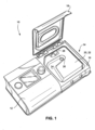
- Fig. 1 shows a respiratory apparatus 10 comprising a flow generator 12 and a humidifier 14.
- the humidifier 14 comprises a humidifier chamber 16 and a lid 18 for the chamber.
- the lid is movable, e.g., pivotable between open and closed positions.
- a water chamber, or humidifier tub 20 is seated or otherwise provided in the humidifier chamber 16 and covered by the lid 18, when the lid 18 is in the closed position.
- the humidification chamber may have a fixed lid rather than a movable/pivotable lid.
- the humidification chamber may have no lid.
- the tub 20 is constructed and arranged to hold a liquid such as water which is used to add moisture to breathable gas.
- the tub 20 includes a tub lid 22 that is configured to direct a flow of breathable gas (airstream) generated by the flow generator 12 along a channel 24 and through an outlet 26 of the channel 24 that directs the gas into the tub 20.
- the tub 20 includes a gas outlet 28 for the humidified flow of breathable gas.
- the gas outlet 28 is connectable to a tube (not shown) configured to deliver the humidified gas flow to a patient interface, e.g. a mask.
- the tub may have different configurations, for example with inlets and/or outlets in different locations.
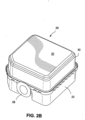
- Figs. 2A and 2B show the exemplary humidifier tub 20 separated from the humidifier chamber 16.
- the tub may be removable from the humidifier chamber 16 to fill the tub with water or clean the tub.
- the lid 22 of the tub connects to a tub bottom or bottom container 30, wherein the lid 22 and tub bottom 30 fit together to form the tub 20.
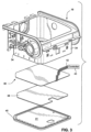
- the tub bottom 30 is in thermal contact with a heating apparatus or heating assembly 36 of the humidifier chamber 16, shown in Fig. 3 .
- the tub bottom 30 comprises a heat conductive material, e.g., a metal material such as aluminum, copper, brass, or stainless steel, or any other alloy or thermally conductive suitable material for conducting heat received from the heating apparatus 36 to the liquid contained inside the tub 20.
- the tub bottom is formed entirely of a metal.
- the tub bottom may have a bottom plate 32 formed of a heat conductive material while the remainder of the tub is formed of another material, e.g., a plastic material.
- the tub bottom and the heating apparatus may be integral, e.g., bottom plate and heating apparatus may be integral. That is, the heating apparatus may form the tub bottom and directly heat the liquid contained inside the tub. While the heating apparatus is shown in Fig. 3 as being planar and at the bottom of the chamber 16, the heating apparatus may have other forms and be at other positions with respect to the chamber and tub. In another example, the heating apparatus may be located in other regions, such as on a side wall of the tub and in direct contact with the liquid to be heated.
- the heating apparatus may be shaped to conform to the side wall 34 of the humidifier chamber 16 such that the heating apparatus abuts against a metal portion of a side wall of the tub.
- the heating apparatus may be provided within the tub and elevated from the tub bottom 30 such that water is provided over top and bottom surfaces of the heating apparatus.
- the design, shape and composition of the tub described herein is exemplary and other tubs and liquid containers may be suitable for the present technology.
- a cradle bottom 40 is provided beneath the heating apparatus 36 and an insulation layer 38 is provided between the heating apparatus 36 and the cradle bottom 40.
- the cradle bottom 40 may be a releasable bottom plate to the humidifier chamber 16.
- the cradle bottom 40 may include a flat surface 41 structured to form a seat for the insulation layer 38 and the heating apparatus 36.
- the insulation layer 38 may be separable from the cradle bottom and the heating apparatus, or bonded to the cradle bottom and/or heating apparatus.
- the insulation layer is structured to prevent excessive heat transfer to the cradle bottom 40 to avoid burning a person touching the bottom cradle or damaging furniture on which the humidifier chamber is seated.
- the insulation layer 38 may not be provided, as heat transfer from the heating apparatus 36 to the tub bottom 30 may be substantially effective and heat dissipation towards the cradle bottom 40 may not be significant.
- Electrical leads 42 are connected to the heating apparatus 36 to provide electrical power to the electrical components of the heating apparatus 36.
- the electrical leads 42 may extend to an electrical coupling within or external of the humidifier chamber 16.
- the electrical leads may connect the heating apparatus to a controller 43 which may be connectable to a power source, such as an electrical wall socket.
- the controller may regulate the voltage or current applied to the heating apparatus.
- the controller may provide one or more of the following: power switch, temperature sensing, fault detection (e.g., open, short, over temperature, poor connection, sensor, water ingress to PCB, CPU, power device, power switch), fault protection, and/or electrical interfacing to heater.
- Figs. 4 and 5 show a heating apparatus or heating assembly 36 according to an example of the present technology.
- the heating apparatus 36 includes a hot plate 44 (also referred to as a heatable element, metal board, or substrate), a thermally conductive laminate layer 46, a heating element 48, a protective layer 50, at least one electrical component 52 (Temperature sensing and/or protection), and electrical leads 42 supplying electricity to the heating element 48 and the at least one electrical component 52.
- the heating apparatus according to an example of the technology provides an assembly that is simpler to process, more efficient and reliable, and lower cost.
- the hot plate 44 comprises a heat conductive material such as aluminum (e.g., anodized aluminum), stainless steel, copper, or any other suitable metal or metal alloy, forming for example a metal alloy plate such as an aluminum plate, a stainless steel plate or a copper plate.
- the metallic hot plate may have a surface treatment such as being anodized to form a protective oxide layer which resists corrosion.
- the hot plate may be thin such as having a thickness in a range of about 0.6 to 1.6 mm, e.g., 1.0 to 1.5 mm. In an example, the hot plate may comprise a substantial portion of the total thickness of the heating apparatus.
- the heating apparatus which includes the hot plate, thermally conductive laminate layer, heating element and protective layer, is similarly thin and may have a thickness in a range of about 0.5 to 1.7 mm, e.g., 1.1 to 1.6 mm, wherein all but about 0.1 to 0.2 mm of the thickness of the heating apparatus is attributed to the hot plate.
- the hot plate may be formed of other suitable materials such as a heat conductive non-metal material, such as a ceramic material and thermal conductive plastics.
- the thermally conductive laminate layer 46 may be a coating, layer or board bonded to the hot plate.
- the thermally conductive laminate layer 46 comprises materials which have good thermal conductivity properties, but are low in electrical conductance, e.g., relatively high electrical resistance, and thus may be referred to as a dielectric laminate layer.
- the thermally conductive laminate layer may be a composite layer of dielectric particles embedded in a filler material, such as a resin.
- the laminate layer 46 may include electrically insulating dielectric materials, such as ceramics, polymers, polymer and ceramic, polymer mixed with inorganic particles, ceramics coated with polytetrafluoroethylene, e.g., Teflon ® , polyimides, boron nitride, alumina, beryllium oxide, aluminum nitride, boron nitride, epoxy composite, and reinforced fiberglass, arranged to form an electrical insulating layer.
- the dielectric breakdown voltage of the laminate layer may be above 2kV.
- the laminate layer 46 may be rigid or flexible, and may be planar or have some other shape which may conform to a bottom and/or side of the tub.
- the thermally conductive laminate layer 46 provides electrical insulation between the heating element 48 and the hot plate 44.
- the thermally conductive laminate layer also is an efficient conductor of the heat generated by the heating element 48 and transfers the heat to the hot plate 44. Heat generated by the heating element 48 flows efficiently through the thermally conductive laminate layer and through the hot plate 44 to the tub and water contained in the tub. Heat generated by the heating element 48 is therefore drawn away or dissipated from the heating element 48 and transferred towards the hot plate 44. That is, the high thermal conductivities of the laminate layer 46 and hot plate 44 provide an effective thermal conductive gradient that allows heat to efficiently flow from the heating element 48, through the laminate layer 46, the hot plate 44 and to the tub 20.
- the hot plate 44 functions as a heat sink that draws heat energy generated in the heating element 48 and distributes the energy to heat the water in the tub. Heat is collected and accumulated at the hot plate 44 for use in heating the tub bottom 30.
- the pressurized gas e.g., 4-20 cmH 2 O
- the laminate layer 46 has a dielectric thermal conductivity in a range of 0.5 to 4 watts per meter Kelvin (W/m.k), e.g., in a range of about 0.5 to 1.00 or greater.
- the laminate layer may be a thin layer, e.g., 20 micrometer ( ⁇ m) to 160 ⁇ m, e.g., 60-120 ⁇ m. The thinness of the laminate layer contributes to the minimal resistance to thermal transmission through the laminate layer.
- the heating apparatus does not include a separate hot plate 44. Rather, the thermally conductive laminate layer 46 itself may form the heating surface. This configuration may provide a flexible circuit arrangement.
- the heating element 48 may be disposed between two layers 57, 58 of thermally conductive laminate material (e.g., flexible polyimide film such as Kapton TM ), as shown in Fig. 4-2 .
- thermally conductive laminate material e.g., flexible polyimide film such as Kapton TM
- One or more thermal conductive substrates, pads, pins or contacts 61 such as a metal substrate, pad, contact or pin (e.g., made from aluminum, stainless steel, copper, etc.) may be bonded to a portion (e.g., an edge portion) of the heating element 48 to form a connector section 59.
- the connector section 59 may be formed prior to forming an additional overmolded protective layer (such as described below) on top of the heating element 48.
- the arrangement of the connector section 59 provides a procession connector which allows direct electrical and/or thermal contact with the heating element 48 such that additional functions (e.g., thermal sensing of the heating element) may be performed.
- the heating element 48 may be formed of electrical resistance heating materials such as copper, electrical heating alloys such as Iron-Nickel, Copper-Nickel, Iron-Chromium-Aluminum, Nickel-Chromium, as well as other materials such as PTC ink materials, Carbon ink materials, copper foil, and other materials having a relatively low electrical resistance or combinations thereof.
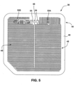
- the heating element 48 may comprises metallic foils, tracks or strips arranged in a serpentine pattern, such as in rows (e.g., see Fig. 5 ). It is noted that each line of the heating element 48 in Fig. 5 represents a "track.”
- the heating element 48 may be printed or applied to the thermally conductive laminate layer 46, as is shown in Fig. 5 .
- the layout of the heating element and the shape of the serpentine pattern may depend on the shape of the bottom plate 32 of the tub. In use, the heating element converts electrical power to heat energy.
- the tracks of the heating element 48 may be evenly distributed across the laminate layer to provide an even heating profile to the hot plate 44.
- the track design of the heating element depends on a number of factors.
- the resistivity of the heating element material affects the track layout design and the track coverage of the laminate layer 46 and the hot plate 44.
- a heating alloy is a better electrical resistance heater material as compared to copper. Therefore, to achieve a similar heating profile, copper heating tracks may be thinner in width (e.g., in a range of about 0.3 mm to 2 mm, e.g., 0.4 to 1 mm) and longer in length as compared to heating alloy or aluminum heating tracks. In such configurations, more area of the heating apparatus may be covered to achieve a similar desired heating profile.
- a person skilled in the art would understand that other track configurations may be provided to produce different heating profiles.
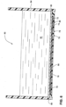
- Fig. 7 shows a heating element 248 including an alternative example of the track layout or pattern.
- the tracks or strips are arranged in a concentric ring-like manner.
- Advantages of this layout include improved thermal distribution as well as improved tolerance for thermal expansion/contraction of the tracks as it heats/cools. This layout also improves the resistance accuracy during the heating process.
- the protective layer 50 may comprise materials commonly used for ⁇ solder masks,' for example polymer or acrylic. Solder masks are conventionally printed on or otherwise applied to coat a printed circuit board (PCB), thermally conductive laminate layer and conductive traces of the heating element during PCB and metal core printed circuit board (MCPCB) manufacturing processes.
- PCB printed circuit board
- MCPCB metal core printed circuit board
- the protective layer is printed on or otherwise applied to coat the heating element 48 and the thermally conductive laminate layer 46.
- the heating element is sandwiched between the protective layer 50 and the thermally conductive laminate layer 46.
- the protective layer 50 may extend over the peripheral edges of the heating element 48 and directly coat portions of the thermally conductive laminate layer 46, e.g., see right edge of apparatus shown in Fig. 4-1 .
- Exemplary materials for the protective layer 50 include, for example, screen printable epoxy mask, liquid photoimageable solder mask (IPSM) and dry film photoimageable solder mask (DFSM).
- the protective layer 50 seals the heating apparatus 36 to prevent current leakage, as well as to protect the laminate layer 46 and the heating element 48 against environmental factors such as corrosion and physical scratching.
- the protective layer 50 may be printed on or otherwise applied to directly coat the surfaces of the hot plate 44 not covered by the laminate layer.
- the protective layer 50 may also provide electrical insulation and some thermal insulation between the heating element 48 and the insulating layer 38 in the cradle bottom 40 of the humidifier chamber 16.
- the protective layer 50 such as a solder mask, may be applied over the laminate layer 46 and the heating element 48 by screen printing, well known mask printing techniques or as a sheet bonded with adhesives to the heating element and laminate layer. Further, stencils may be positioned over certain locations on the heating element and laminate layer so that the contact pads and possibly other locations are not coated by the protective layer. After the protective layer is printed, applied or otherwise bonded to the heating element and laminate layer, the stencil may be removed to expose the contact pads and other locations which are to be exposed.
- Contact pads and/or other conductive portions of the heating element may be exposed through the protective layer 50 to allow for connection of the electrical leads to the heating element, e.g., by surface mounting technology. These openings in the protective layer for the contact pads may be automatically applied during an automated printing or coating process.
- the electrical leads 42 provide a conductive path for power from an electrical power source to be applied to the heating element 48.
- the electrical leads may be coupled to electrical wires that fit into a power source, such as a transformer or inverter or into an electrical power wall-socket via appropriate isolation.
- a power source such as a transformer or inverter or into an electrical power wall-socket via appropriate isolation.
- the heating element may include conductive or contact pads 53, 54, printed or placed on the laminate layer 46.
- the conductive pads provide an electrical connection point for the electrical leads 42, e.g., conductive pad 53 providing a positive power terminal and conductive pad 54 providing a negative power terminal. Electrical power flows from a power source, through the leads, the power terminals and the heating element 48. Additional contact pads may be used to provide electrical connections to other electrical device(s) or contacts (e.g., spring contact or spring contacts) on the laminate layer 46.
- the electrical components 52 noted with respect to Fig. 4-1 may include a thermo sensor 52A and a thermo fuse 52B which are connected to tracks of the heating element 48.
- the electrical connection provided by contact pad 56 may be between the thermo sensor 52A and another source of electrical power provided by a different set of leads for separately providing power to the thermo sensor 52A. Another source of electrical power may be provided if the power requirements of the other electrical device(s), e.g., thermo sensor 52A, differ from the power requirements for the heating element.
- the thermo fuse 52B may be mounted on top of the solder mask and connected to the contact pads which are in electrical contact with the heating element. The thermo fuse stops current flow through the heating element if the heat becomes excessive.
- the electrical connections between the contact pads and the electrical leads or sensor wires may be made by soldering or any other known electrical connection processes, for example automated surface mounting technologies.
- a nominal voltage source of between 12 Volts (V) and 36V (such as between 8V and 40V) provides power to the heating element 48.
- Other voltages may be used in accordance with suitable operational parameters of the heating element 48.
- the heating element 48 may substantially cover the entire area of the laminate layer, while allowing a margin for clamping in a coating treatment process to apply the printed protective layer 50 (e.g., applying a solder mask).
- the heating apparatus 36 may be formed using known printed circuit board (PCB) manufacturing techniques for making metal PCBs, such as metal core printed circuit board (MCPCB) techniques. These techniques are highly automated and are adapted to apply conductive tracks on metal PCBs.
- PCB printed circuit board
- MCPCBs metal core printed circuit board
- metal plates serve both as a printed circuit board base and a heat sink for electronic components mounted to the plate. Heat from the electronic components is dissipated by the metal plate to avoid overheating of the electronic components.
- the metal plate may be formed of any appropriate heat conducting metal, for example aluminum (aluminium), stainless steel, or other heat conducting metals, or heat conducting polymers or plastics.
- the heating element 48 may be applied to the thermally conductive laminate layer 46 using MCPCB manufacturing techniques for making metal PCBs.
- the heating element may be applied by printing the conductive tracks on the laminate layer 46.
- the heating element may also be formed by applying a conductive sheet to the laminate layer, applying a mask to the sheet shaped as a mirror image of the desired pattern of the heating element and etching away the portions of the conductive sheet not covered by the mask.
- the heating element 48 may also be formed on the laminate layer 46 by vacuum deposition techniques. Further, the serpentine pattern of the heating element may be selected based on the shape of the bottom of the water tub and the amount of heat energy to be delivered to the tub.
- a PCB including a metal layer, a dielectric layer, and a copper layer may be selected based on size/performance characteristic requirements. Copper heating tracks are created in the copper layer according to track specification, e.g., by etching. A printed protective layer (e.g., solder mask) is applied to cover the heating tracks. The tracks/printed protective layer may accommodate for electrical connection points for surface mounting (or solder) electrical components (e.g., thermo fuse, thermo sensor).
- solder solder mask
- the assembly process disclosed herein for the heating apparatus may be fully or nearly fully automated, which allows for the production of heating apparatuses having high quality and uniform consistency.
- the assembly process disclosed herein may also result in reduced assembly costs and reduced repair or replacement costs for the heating element due to the automation.
- such PCB technique uses advanced heat transfer structure, material and technology, provides much simpler structure, provides excellent thermal performance, involves much less safety concerns, provides easy quality control and high yield, and/or provides easy mass production capacity increase and multiple supply.
- Fig. 5 shows an example of the heating apparatus 36 formed by metal printed circuit board printing and manufacturing processes.
- Fig. 5 shows the heating element 48 arranged in rows on the thermally conductive laminate layer 46.
- the laminate layer 46 may be coincident or coextensive with the hot plate 44 (e.g.; as shown in Fig. 5 which shows the hot plate 44 below the laminate layer 46), or the perimeter of the hot plate 44 may extend slightly beyond the perimeter of the laminate layer 46 (e.g., as shown in Fig. 4-1 ).
- the heating apparatus is provided as a separate and distinct structure from the humidifier tub which is adapted to contact the tub to heat liquid contained inside the tub.
- the heating apparatus may be integral with the tub and form the tub bottom so as to directly heat liquid contained inside the tub. Examples of such direct heating apparatus are described below.
- Fig. 6 shows a humidifier tub or water tub 60 for heating water 62 according to an example of the present technology.
- the tub may be suitable for seating in a humidifier chamber or may be provided as a stand-alone device.
- the tub 60 includes sidewalls 64, or sidewall portions, or tub sidewalls extending around the entire perimeter of the tub and a bottom wall 66 which joins to the sidewalls.
- a heating apparatus or heating assembly 68 is incorporated into the bottom wall 66.
- the sidewalls 64 and bottom wall 66 e.g., formed of plastic
- the bottom wall 66 is molded over peripheral edges of the dielectric layer 72, heating element 74, and protective layer 76.
- the protective layer may cover one or more layers of the heating apparatus.
- the heating apparatus 68 is formed as a lamination of a hot plate 70, a thermally conductive dielectric layer 72, a heating element 74 and a protective layer 76.
- the hot plate may be a metal plate having a first side with an anodized coating which is adapted to form the bottom interior surface of the tub exposed to the water 62.
- the opposite side of the hot plate receives the thermally conductive dielectric layer 72 which may be a resin with dielectric particles, as is described above.
- the heating element 74 may be a serpentine track of a metallic foil, e.g. forming a serpentine track of conductive foil, that is printed on or otherwise applied to a side of the dielectric layer 72 opposite to the hot plate 70.
- Contact pads 78 may be arranged at each of the ends of the track of the heating element or close to the edge of the hot plate to allow for a spring electrical contact.
- the contact pads 78 may be exposed through the protective layer 76. Further the contact pads may be formed with raised terminals which protrude slightly from the bottom wall 66 of the tub. Such arrangement allows the contact pads 78 to engage power terminals at, for example, the bottom of a humidifier chamber which provides electrical power to the heating element.
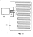
- FIG. 13 illustrates a direct-heating humidifier tub including a heating apparatus 668 that forms the bottom wall of the tub (e.g., heating apparatus provided to bottom of tub by overmolding or clip-in).
- Fig. 13 shows the hot plate 670, heating element 674 and protective layer 676 of the heating apparatus, with a contact pad 678 exposed through the protective layer 676.
- the exposed contact pad 678 may engage a power terminal or spring electrical contact 682 at the bottom of a humidifier chamber when the tub is engaged with the humidifier chamber, e.g., push-down electrical contact connection configuration.
- edges 80 at the perimeter of the hot plate 70 may fit, e.g., snap, into grooves at the lower edge of the sidewalls 64.
- the edges 80 may extend beyond the edge of the protective layer 76, heating element 74 and dielectric layer 72.
- the joint between the edges 80 of the hot plate 70 and the sidewalls 64 may be sealed to secure the heating assembly to the sidewalls and to prevent water leakage from the tub.
- the sidewalls 64 may be overmolded to the edges 80 of the hot plate 70.
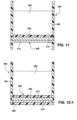
- the heating assembly may include a protective coating 469, 569 provided over the hot plate, as shown in Figs. 11 and 12 .
- the protective coating may be overmolded over the hot plate to provide a water and/or vapor sealed protection layer across the heating surface.
- the protective coating is thermally conductive so as to effectively transfer heat from the hot plate to the water in the tub.
- the protective coating is preferably formed of a bio-compatible material and may be formed of silicone, Teflon ® , UV cured polymers or other thermally conductive plastic materials, such as CoolPoly TM products.
- the protective coating may also provide an easily cleanable surface.
- the protective coating may allow the heater assembly to be inserted or located directly within the water tub body, which may provide enhanced thermal performance.
- the use of a protective over molded coating is further described in US 61/611,137, filed 15 March 2012 .
- Fig. 11 shows an example of a humidifier tub with an open base or bottom.
- the tub 460 includes plastic molded sidewalls 464 and a heating apparatus 468 that cooperate to define a water chamber or compartment for water 462.
- the heating apparatus includes an overmolded protective coating 469, a thermally conductive hot plate 470 (e.g., metal hot plate), and a heating element 474 having heating tracks abutting against the hot plate 470.
- the heating apparatus is spaced upwardly from the lower ends of the sidewalls 464.
- the sidewalls may be overmolded onto the heating apparatus, without a bottom wall or bottom protective layer. Other materials with high thermal insulation may be used for the overmold.
- an insulator or bottom wall may be provided to the tub below the heating element 474.
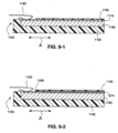
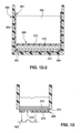
- Fig. 12-1 shows an example of a humidifier tub with a closed base or bottom.
- the tub 560 includes plastic molded sidewalls 564, a plastic molded bottom wall 566, and a heating apparatus 568 that cooperate to define a water chamber or compartment for water 562.
- the heating apparatus includes an overmolded protective coating 569, a thermally conductive hot plate S70(e.g. metal hot plate), and a heating element 574 providing heating tracks.
- the sidewalls and bottom wall may be overmolded onto the heating apparatus.
- an inner portion of the tub 560 may be overmolded with thermally conductive plastics such that a hot plate 570 and heating element 574 are embedded in the overmold to form a heating apparatus 868.
- the overmold 861 includes a bottom wall 867 overmolded onto the bottom wall 566 of the tub and an intermediate wall 872 which covers the hot plate 570.
- the overmold 861 may also include sidewalls 863 overmolded onto the tub side walls 564. This arrangement may form a bio-compatible, cleanable, water/vapor sealed protection layer.
- the entire assembly may be formed in a different configuration such that a thermally conductive hot plate is no longer required, as shown in Figs. 15-1 and 15-2 .
- a support substrate 990 is provided on the lower surface of the tub onto which the heating element 974 is bonded or applied in the same manner described above for applying the heating element 48 to the hot plate 44.
- the heater assembly may be assembled directly into a surface of a water tub, such as the bottom surface.
- a thermally conductive protective coating 969 is overmolded over the heating element 974 to provide electrical insulation, corrosion resistance and/or damage protection.
- the heating element 974 is positioned towards the water to be heated and the support substrate 990 is positioned relatively away from the water.
- the support substrate 990 serves primarily as a base for receiving the printed circuit and does not function as a heat sink or conductive means to heat the water.
- the heater assembly is flipped upside down as compared to the embodiments described above using the metal hot plate such that heat transfer occurs in the opposite direction.
- the heating element 974 is essentially exposed to the water and consequently may provide improved thermal conductivity and thermal efficiency. Such an arrangement may also provide for more accurate or direct sensing of the temperature of the water.
- the support substrate 990 may be formed of a lower cost PCB type material such as a composite epoxy material (CEM) of different grades (e.g., CEM3), a fiberglass reinforced epoxy laminate such as FR-4, or other such PCB type materials.
- CEM composite epoxy material
- the support substrate 990 may also be configured to provide thermal insulation to the outer surfaces of the tub.
- the electrical connections are located on the internal surfaces of the tub.
- the electrical connections for thermal sensing or safety switches may be directly coupled to the heating element 974 prior to overmolding the heating element 974 within the tub.
- the protective coating or layer 1073 may include a thin layer of stainless steel that is applied over the heating element 1074.
- the stainless steel layer may be applied in any suitable manner that provides thermal contact between the stainless steel and the heating element.
- the thin layer of stainless steel may have a thickness of less than 1.2 mm (e.g., 0.05 to 1 mm).
- a thermally conductive laminate layer 1075 (e.g., Kapton TM film) may be provided between the protective coating 1073 and the heating element 1074 to provide electrical insulation.
- the thermally conductive laminate layer 1075 may also include a thermal adhesive (e.g., double sided adhesive) to attach the protective layer 1073.
- the stainless steel layer may provide one or more of the following benefits: a protective cover to the heating element, anti-corrosion protection, and rigidity to the heater assembly (e.g., the stainless steel layer may form the heater assembly into a rigid structure).
- the heating element 1074 may be formed without a thick support substrate 1090 such that the thin layer of stainless steel provides support to the flexible heater element while also providing a more compliant heater assembly that may be configured to conform to the shape of the water tub.
- the heating apparatus 68 may have exposed contact points (i.e., exposed contact pads 78) so that when the tub is placed on the bottom of the humidifier chamber, the contact points engage with counterpart contact points adapted to supply electrical power.
- the contact points within the humidifier chamber may be spring loaded, so that such contact points must be depressed to effect an electrical connection, e.g., contact points within the humidifier chamber engage only when the humidifier lid is closed to retain the humidifier tub within the humidifier chamber.
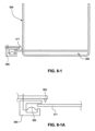
- Figs. 8 to 10 show another example of an electrical connection for a heating apparatus.
- the heating apparatus 368 integrated into the bottom of the humidifier tub 360 includes an exposed portion 371 adapted to engage an electrical contact structure 380 provided to the humidifier chamber when the tub is slid into an operative position within the humidifier chamber, i.e., slide-in type electrical connection.
- the electrical contact structure 380 is in the form of a socket and includes a metallic spring arm 382 therewithin.
- the exposed portion 371 of the heater apparatus engages the metallic spring arm 382 within the electrical contact structure 380 to effect an electrical connection.
- An advantage of this connection is that there is a "self cleaning" aspect which removes the build up of metal oxides on the connection points, since every slide-in/slide-out brushes one surface against another and wipes off any oxide build up.
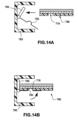
- Figs. 14A and 14B show another example of a slide-in type electrical connection for a heating apparatus.
- the metallic spring arm 782 is pivotally mounted within the electrical contact structure 780.
- the end portion of the heating apparatus 786 may slide into the contact structure 780 and abut against stub 785 which will pivot and raise the spring arm 782 into electrical contact with an exposed contact pad 778 at the bottom of the heating apparatus, e.g., pivoting type slide-in connection.
- Such pivotal connection ensures that the spring arm 782 only contacts the exposed contact pad in use, i.e., spring arm avoids contact and potential wear of protective surfaces at the bottom of the heating apparatus.
- a protective contact edge 1183 may be formed in a connector region by overmolding an additional outer protective coating 1192 around at least a portion of the heater assembly.
- a heater assembly includes a support substrate 1190, a heating element 1174 (e.g., a copper layer), an overmolded protective coating 1193 on top of the heating element 1174, and the outer protective coating 1192 overmolded to a bottom surface of the support substrate 1190 and around an outer edge of the heater assembly to provide a protective coating along an edge of the connector region of the heater assembly.
- the heating element may be exposed from the outer protective coating 1192 in the connector region to provide a contact portion for an electrical contact arm 1182.
- the contact portion may be provided with a layer of Nickel (e.g., 20 to 80 ⁇ m) and a layer of Gold (e.g., 20 to 50 ⁇ m) over the Nickel to protect this area.
- the outer protective coating 1192 may provide a rigid or semi-rigid support to the heater assembly. The outer protective coating 1192 may also protect the electrical connection from water egress.
- Temperature sensing of the heating apparatus may be provided for fault mitigation and temperature feedback control. For example, the temperature of the heating apparatus or water may be determined, and then power may be cut off to the heating element if the temperature is too high. For temperature feedback, the temperature of the heating apparatus or water may be determined to better control the powering profile and coordinate the required level of vaporization/humidification.
- the temperature of the heating apparatus or water may be determined in alternative manners.
- Alternative examples of sensors for determining temperature of the heating apparatus are described below.
- a non-contact type sensor may be provided to determine the temperature of the heating apparatus. Such non-contact type sensor is spaced from the heating surface or heating tracks of the heating apparatus.
- an infrared (IR) sensor may be located near the heating surface of the heating apparatus and sense the radiation (heat) given off the heating apparatus to determine the temperature of the heating apparatus.
- IR infrared
- An example of such arrangement is shown in Fig. 8-1A which shows an IR sensor 383 near the heating surface of the exposed portion 371 of the heating apparatus.
- a convection sensor may be located near the heating surface of the heating apparatus (e.g., similarly positioned to the sensor shown in Fig. 8-1A ) and sense the temperature of the air in the gap between the convection sensor and the heating apparatus to determine the temperature of the heating apparatus.
- a contact type sensor may be provided to determine the temperature of the heating apparatus. Such contact type sensor is in contact with the heating surface or heating tracks of the heating apparatus.
- the senor may include a thermo-resistive material in which material resistance changes as the temperature varies. By measuring the resistance change, the temperature may be determined.
- the senor may include a thermo-magnet switch in which the magnetic field strength changes with the change of temperature. By measuring the magnetic field strength change, the temperature may be determined.
- the senor may include a bi-metal strip material in which the shape or springiness of the metal changes with the temperature. By measuring the shape or springiness change, the temperature may be determined.
- An exemplary advantage of this example is that the strip material may disconnect at a particular temperature, thus providing a thermo fuse for the system.
- Such off-heater sensor arrangements may also be a combined sensor and manual resettable switch.
- thermo sensor 52A may be provided to the heating element to measure the temperature of the heating tracks and a thermo fuse 52B may be provided to stop current flow through the heating element if the heat becomes excessive.
- the heating track itself may also be a temperature sensor.
- the heating apparatus may be formed using known PCB manufacturing techniques for making metal PCBs, such as MCPCB techniques.
- MCPCB techniques such as MCPCB techniques.
- Such heating apparatus according to the present technology provides a heating profile that is substantially evenly distributed across the heater apparatus. For example, temperature differences ( ⁇ T) across the hot plate during heating up is much lower (indicates much higher thermal conductivity and fast heat transfer), low thermal stress on hot plate and surrounded material temperature ramp up and operation, low thermal/mechanical stress on hot plate and surrounded material during temperature ramp up and operation, low back side temperature which will not heat up the casing bottom.
- the temperature transfer from the heating tracks to the metal hot plate is efficient and therefore the temperature of the surface of the hot plate is likely to be similar to that of the heating track (low thermal gradient/heat sink).
- Such conversion circuit may also be used for fault detection and protection, such as heater over temperature, open circuit, or poor connection or shorting.
- the heating apparatus may. provide a heating surface temperature that can only reach a maximum temperature for a chosen input power. This is due to efficient heat transfer from the heating track to the heating surface, effective heat dissipation from the heating surface, and copper heating tracks reaching a limit temperature with a given power input.
- a thermo fuse (to mitigate against overheating) may possibly be removed as the heating apparatus would have over-heating self protection capability. Removal of the thermo fuse may provide savings in componentry and assembly costs.
- the heating tracks may be formed from polymer thick film (PTF) 1274 in combination with copper conductors (e.g., heating tracks) 1295 that are printed on a hot plate (e.g., the hot plate 44 described in the examples above) or a support substrate 1190.
- the copper conductor 1295 and the PTF 1274 are provided in appropriate quantities to provide variation in heating across the heating element.
- the PTF 1274 may comprise a positive temperature coefficient (PTC) to provide a sensing and thermal protection function.
- PTC positive temperature coefficient
- the copper conductor 1295 forms a contact portion and act as conductors for electricity from an electrical contact arm 1182 and the PTF 1274 as the heater.
- the contact portion may be provided with a layer of Nickel (e.g., 20 to 80 ⁇ m) and a layer of Gold (e.g., 20 to 50 ⁇ m) over the Nickel to protect this area.
- the heater may also be formed by the copper tracks 1295 in combination with the PTF 1274 to achieve the required heating and protection properties.
- one or more sections of PTF 1274 may be provided in series with the copper tracks 1295 to form a thermal fuse.
- the heating apparatus may be enclosed or otherwise covered in stainless steel which provides the advantage of protecting the heating apparatus from corrosion.
- This process may be used as an alternative, or in conjunction with the step of anodizing the hot plate.
- the result of this manufacturing step would be a heating apparatus that is enclosed or otherwise covered in stainless steel.
- another thermally conductive material that resists scratching, and resists corrosion such as hard anodized stamped aluminium may be used to enclose or cover.
- the present technology is particularly useful in a lower temperature heating application, e.g., less than 100C, or less than 80C, or less than 70C.
- the power output may be less than about 5 W/cm2, or less than about 2 W/cm2, or less than about 1 W/cm2, for example around 0.6 W/cm2.
- a higher temperature application may require a power output of around 60 W/cm2.
- the present technology facilitates the use of lower cost materials and lower cost processes than may be required for a higher temperature application.
- the manufacturing process of etching may be used instead of printing thermally conductive inks. The etching process may give rise to a more accurate heating track than the printing process.
- the present technology allows the use of a cheaper dielectric material, such as an organic material whereas a high temperature process and application requires an inorganic dielectric and concomitant higher material and process costs. Furthermore the present technology allows the use of a lower cost hot plate, for example one made of aluminium or another lower cost material.
Landscapes
- Health & Medical Sciences (AREA)
- General Health & Medical Sciences (AREA)
- Biomedical Technology (AREA)
- Public Health (AREA)
- Anesthesiology (AREA)
- Veterinary Medicine (AREA)
- Heart & Thoracic Surgery (AREA)
- Hematology (AREA)
- Life Sciences & Earth Sciences (AREA)
- Animal Behavior & Ethology (AREA)
- Emergency Medicine (AREA)
- Engineering & Computer Science (AREA)
- Pulmonology (AREA)
- Chemical & Material Sciences (AREA)
- Chemical Kinetics & Catalysis (AREA)
- Surface Heating Bodies (AREA)
- Air Humidification (AREA)
- Resistance Heating (AREA)
- Thermotherapy And Cooling Therapy Devices (AREA)
- Instantaneous Water Boilers, Portable Hot-Water Supply Apparatuses, And Control Of Portable Hot-Water Supply Apparatuses (AREA)
- Central Heating Systems (AREA)
- Air-Conditioning For Vehicles (AREA)
Applications Claiming Priority (4)
| Application Number | Priority Date | Filing Date | Title |
|---|---|---|---|
| AU2011902350A AU2011902350A0 (en) | 2011-06-16 | Heating Apparatus | |
| US201161628622P | 2011-11-03 | 2011-11-03 | |
| EP12800518.8A EP2720746B1 (en) | 2011-06-16 | 2012-06-15 | Humidifier |
| PCT/AU2012/000693 WO2012171072A1 (en) | 2011-06-16 | 2012-06-15 | Humifier and layered heating element |
Related Parent Applications (1)
| Application Number | Title | Priority Date | Filing Date |
|---|---|---|---|
| EP12800518.8A Division EP2720746B1 (en) | 2011-06-16 | 2012-06-15 | Humidifier |
Publications (2)
| Publication Number | Publication Date |
|---|---|
| EP3714930A1 EP3714930A1 (en) | 2020-09-30 |
| EP3714930B1 true EP3714930B1 (en) | 2023-12-06 |
Family
ID=47356434
Family Applications (2)
| Application Number | Title | Priority Date | Filing Date |
|---|---|---|---|
| EP20152759.5A Active EP3714930B1 (en) | 2011-06-16 | 2012-06-15 | Humidifier with layered heating element |
| EP12800518.8A Active EP2720746B1 (en) | 2011-06-16 | 2012-06-15 | Humidifier |
Family Applications After (1)
| Application Number | Title | Priority Date | Filing Date |
|---|---|---|---|
| EP12800518.8A Active EP2720746B1 (en) | 2011-06-16 | 2012-06-15 | Humidifier |
Country Status (7)
| Country | Link |
|---|---|
| US (5) | US9821135B2 (zh) |
| EP (2) | EP3714930B1 (zh) |
| JP (4) | JP6054382B2 (zh) |
| CN (3) | CN107335121B (zh) |
| AU (1) | AU2012269735B2 (zh) |
| NZ (1) | NZ773086A (zh) |
| WO (1) | WO2012171072A1 (zh) |
Families Citing this family (155)
| Publication number | Priority date | Publication date | Assignee | Title |
|---|---|---|---|---|
| NZ617632A (en) | 2007-06-05 | 2015-02-27 | Resmed Ltd | Electrical heater with particular application to humidification and fluid warming |
| US9505164B2 (en) | 2009-12-30 | 2016-11-29 | Schauenburg Technology Se | Tapered helically reinforced hose and its manufacture |
| DE102008022663B4 (de) | 2008-05-07 | 2012-10-31 | Schauenburg Hose Technology Gmbh | Stretch-Schlauch |
| US9964238B2 (en) | 2009-01-15 | 2018-05-08 | Globalmed, Inc. | Stretch hose and hose production method |
| CN107335121B (zh) | 2011-06-16 | 2022-06-03 | 瑞思迈私人有限公司 | 加湿器和层式加热元件 |
| US10286167B2 (en) | 2011-07-13 | 2019-05-14 | Fisher & Paykel Healthcare Limited | Impeller and motor assembly |
| US10317098B2 (en) | 2012-03-15 | 2019-06-11 | ResMed Pty Ltd | Heating apparatus |
| AU2013296145B2 (en) | 2012-07-27 | 2015-12-17 | ResMed Pty Ltd | Patient interface and method for making same |
| US11116928B2 (en) | 2012-11-16 | 2021-09-14 | ResMed Pty Ltd | Positioning and stabilising structure for a patient interface system |
| WO2014097030A1 (en) | 2012-12-18 | 2014-06-26 | Fisher & Paykel Healthcare Limited | Impeller and motor assembly |
| NZ630702A (en) | 2013-01-16 | 2017-02-24 | Resmed Ltd | Patient interface and method for making same |
| US9838586B2 (en) * | 2013-01-31 | 2017-12-05 | Cognex Corporation | Portable apparatus for use in machine vision |
| EP2968829B1 (en) | 2013-03-15 | 2021-04-21 | ResMed Pty Ltd | Water reservoirs and methods of preventing overfilling in a humidifier reservoir |
| US9861778B2 (en) | 2013-03-15 | 2018-01-09 | Resmed Limited | Humidifier reservoir |
| NZ623462A (en) | 2013-04-12 | 2016-02-26 | Resmed Ltd | Neck strap, crown strap assembly and headgear for a breathing mask |
| EP2996752B1 (en) | 2013-05-14 | 2019-02-13 | ResMed Limited | Oro-nasal patient interface |
| CN108434575B (zh) | 2013-05-14 | 2022-01-18 | 瑞思迈私人有限公司 | 口鼻患者接口 |
| NZ733217A (en) | 2013-06-25 | 2019-01-25 | ResMed Pty Ltd | Outlet connection assembly and method of making the same |
| US10549060B2 (en) | 2013-06-25 | 2020-02-04 | ResMed Pty Ltd | Outlet connection assembly and method of making the same |
| WO2015000025A1 (en) | 2013-07-01 | 2015-01-08 | Resmed Limited | Motor drive system for respiratory apparatus |
| NZ750820A (en) | 2013-07-29 | 2020-08-28 | ResMed Pty Ltd | Heat and moisture exchanger for a patient interface |
| GB2533515B (en) * | 2013-09-13 | 2020-01-15 | Fisher & Paykel Healthcare Ltd | Heater base with a front guard and an anti-racking mechanism |
| NZ631446A (en) | 2013-10-03 | 2016-05-27 | Resmed Ltd | Mask vent with side wall |
| NZ717147A (en) | 2013-10-21 | 2017-08-25 | Resmed Ltd | Methods of detecting a quantity of water in a humidifier |
| US11318275B2 (en) | 2013-10-30 | 2022-05-03 | ResMed Pty Ltd | Control for pressure of a patient interface |
| US9726390B2 (en) | 2013-10-30 | 2017-08-08 | Fisher & Paykel Healthcare Limited | Humidifier arrangements and control systems |
| WO2015070289A1 (en) | 2013-11-15 | 2015-05-21 | Resmed Limited | Patient interface and method for making same |
| CN103656830A (zh) * | 2013-12-13 | 2014-03-26 | 科迈(常州)电子有限公司 | 一种家用呼吸机加湿器及其湿度控制方法 |
| CN114404752B (zh) | 2013-12-17 | 2023-10-27 | 瑞思迈私人有限公司 | 呼吸压力治疗系统 |
| USD743556S1 (en) * | 2014-02-19 | 2015-11-17 | Resmed Limited | Positive airway pressure delivery console |
| JP1525591S (zh) * | 2014-02-19 | 2018-05-21 | ||
| WO2015135040A1 (en) * | 2014-03-13 | 2015-09-17 | Resmed Limited | A humidifier for a respiratory therapy device |
| USD762843S1 (en) | 2014-03-18 | 2016-08-02 | Resmed Limited | Air delivery tube |
| US10052449B2 (en) | 2014-03-21 | 2018-08-21 | Fisher & Paykel Healthcare Limited | Heating arrangements for humidification systems |
| US10792450B2 (en) | 2014-04-23 | 2020-10-06 | ResMed Pty Ltd | Device for retaining humidity in a patient interface |
| NZ630742A (en) | 2014-05-01 | 2016-02-26 | Resmed Ltd | A patient interface |
| WO2015193408A1 (en) | 2014-06-17 | 2015-12-23 | Resmed Limited | A seal forming structure for a patient interface and a tool and method of manufacturing the seal forming structure |
| JP6845017B2 (ja) | 2014-07-02 | 2021-03-17 | レスメド・プロプライエタリー・リミテッド | カスタマイズされた患者インターフェースとその製造方法 |
| US9649468B2 (en) | 2014-09-03 | 2017-05-16 | Fisher & Paykel Healthcare Limited | Respiratory gas humidifier |
| CA3175235A1 (en) * | 2014-09-03 | 2016-03-10 | Fisher & Paykel Healthcare Limited | Deterministically controlled humidification system |
| US10632275B2 (en) | 2014-09-16 | 2020-04-28 | ResMed Pty Ltd | Headgear comprising spacer fabric |
| WO2016041019A1 (en) | 2014-09-18 | 2016-03-24 | Resmed Limited | Gas washout vent for patient interface |
| TWI694673B (zh) * | 2014-09-18 | 2020-05-21 | 美商瑞思邁發動機及馬達技術股份有限公司 | 呼吸治療裝置及控制其感應馬達之方法 |
| NZ769319A (en) | 2014-10-24 | 2022-08-26 | Resmed Inc | Respiratory pressure therapy system |
| CN107683160B (zh) | 2014-11-26 | 2021-08-17 | 瑞思迈私人有限公司 | 纺织品患者接口 |
| US10744295B2 (en) | 2015-01-13 | 2020-08-18 | ResMed Pty Ltd | Respiratory therapy apparatus |
| WO2016119018A1 (en) | 2015-01-30 | 2016-08-04 | Resmed Asia Operations Pty Limited | Patient interface comprising a gas washout vent |
| US10864346B2 (en) | 2015-03-05 | 2020-12-15 | ResMed Pty Ltd | Humidifier for a respiratory therapy device |
| EP3268651B1 (en) | 2015-03-10 | 2023-01-18 | ResMed Pty Ltd | Fluid connector with face seal |
| USD790683S1 (en) | 2015-03-11 | 2017-06-27 | Resmed Limited | Pressurized air delivery console |
| NZ774238A (en) | 2015-03-25 | 2023-12-22 | ResMed Pty Ltd | Patient interface with blowout prevention for seal-forming portion |
| AU2016203593B1 (en) * | 2015-06-02 | 2016-11-10 | Roger Foote | Medical humidifier |
| EP3985260A1 (en) | 2015-06-16 | 2022-04-20 | ResMed Pty Ltd | Impeller with inclined and reverse inclined blades |
| US11007343B2 (en) | 2015-06-30 | 2021-05-18 | ResMed Pty Ltd | Gas flow regulating apparatus for respiratory treatment |
| NZ773771A (en) | 2015-07-07 | 2023-12-22 | ResMed Pty Ltd | Respiratory pressure therapy device |
| JP6991125B2 (ja) | 2015-07-20 | 2022-01-12 | レスメド・プロプライエタリー・リミテッド | 減容部材を備えた患者インターフェース |
| EP3324767B1 (en) | 2015-07-24 | 2020-07-08 | ResMed Pty Ltd | Headgear with covered edge |
| WO2017027906A1 (en) | 2015-08-14 | 2017-02-23 | Resmed Limited | Monitoring respiratory pressure therapy |
| CN112755355A (zh) | 2015-09-23 | 2021-05-07 | 瑞思迈私人有限公司 | 弯管组件 |
| CN108617165B (zh) | 2015-09-23 | 2023-11-14 | 瑞思迈私人有限公司 | 具有泡沫密封形成结构的患者接口 |
| US10799661B2 (en) | 2015-09-23 | 2020-10-13 | ResMed Pty Ltd | Patient interface with a seal-forming structure having varying thickness |
| EP3352827B1 (en) | 2015-09-23 | 2022-01-05 | ResMed Pty Ltd | Patient interface with a seal-forming structure having varying thickness |
| NZ770246A (en) | 2015-09-23 | 2023-04-28 | ResMed Pty Ltd | Patient interface |
| JP7111613B2 (ja) | 2015-09-23 | 2022-08-02 | レスメド・プロプライエタリー・リミテッド | 発泡体シール形成構造を用いた患者インターフェース |
| CN112657030A (zh) | 2015-09-23 | 2021-04-16 | 瑞思迈私人有限公司 | 包括具有不同厚度的密封形成结构的患者接口 |
| EP3922890B1 (en) | 2015-09-23 | 2023-11-29 | ResMed Pty Ltd | Vent adaptor for a respiratory therapy system |
| EP3146991B1 (en) | 2015-09-25 | 2022-01-26 | ResMed Pty Ltd | Improved patient interface component |
| US10821257B2 (en) | 2015-10-05 | 2020-11-03 | ResMed Pty Ltd | Respiratory system with humidifier and conformable reservoir |
| US11504492B2 (en) | 2015-10-08 | 2022-11-22 | ResMed Pty Ltd | Air conduit for a respiratory device |
| AU2016367428B2 (en) | 2015-12-11 | 2021-12-09 | Fisher & Paykel Healthcare Limited | Humidification system |
| US11896772B2 (en) * | 2015-12-23 | 2024-02-13 | Fisher & Paykel Healthcare Limited | Heating arrangements for humidification systems |
| USD844787S1 (en) | 2015-12-28 | 2019-04-02 | Resmed Limited | Pressurized air delivery console |
| CN114191672B (zh) | 2016-01-14 | 2024-02-27 | 瑞思迈私人有限公司 | 口鼻患者接口 |
| CN117919561A (zh) | 2016-01-21 | 2024-04-26 | 瑞思迈私人有限公司 | 用于患者接口的可调节头带管 |
| USD805630S1 (en) | 2016-02-02 | 2017-12-19 | Resmed Limited | Air delivery tube |
| USD857189S1 (en) | 2016-03-11 | 2019-08-20 | ResMed Pty Ltd | Battery pack for an air delivery module |
| US10695522B2 (en) | 2016-03-14 | 2020-06-30 | ResMed Pty Ltd | Respiratory pressure therapy device |
| CN109156050A (zh) * | 2016-04-07 | 2019-01-04 | 美题隆公司 | 氧化铍整体式电阻加热器 |
| CN109414557B (zh) | 2016-04-28 | 2022-08-30 | 瑞思迈私人有限公司 | 患者接口 |
| WO2018018074A1 (en) | 2016-07-25 | 2018-02-01 | Resmed Limited | Respiratory pressure therapy system |
| WO2018035579A1 (en) | 2016-08-26 | 2018-03-01 | Resmed Limited | Respiratory pressure therapy system with nebulising humidifier |
| CN109906098B (zh) | 2016-09-21 | 2021-12-07 | 瑞思迈私人有限公司 | 用于患者接口的换气口和换气口适配器 |
| US11273276B2 (en) | 2016-10-04 | 2022-03-15 | ResMed Pty Ltd | Patient interface with movable frame |
| US10764963B2 (en) | 2016-10-07 | 2020-09-01 | S. C. Johnson & Son, Inc. | Volatile material dispenser |
| EP3538190B1 (en) | 2016-11-11 | 2023-09-06 | ResMed Pty Ltd | Gas washout vent for patient interface |
| WO2018094452A1 (en) | 2016-11-22 | 2018-05-31 | Resmed Limited | Humidifier reservoir |
| FR3061437B1 (fr) | 2017-01-05 | 2019-01-25 | Air Liquide Medical Systems | Humidificateur pour appareil d'assistance respiratoire |
| AU2017391760B2 (en) | 2017-01-06 | 2023-08-31 | ResMed Pty Ltd | Vent adaptor for a respiratory therapy system |
| WO2018126299A1 (en) | 2017-01-09 | 2018-07-12 | Resmed Limited | A humidifier for a respiratory therapy device |
| CN106765000B (zh) * | 2017-01-18 | 2019-04-30 | 广东美的厨房电器制造有限公司 | 电加热设备 |
| EP3565700B1 (en) | 2017-01-30 | 2024-05-15 | GlobalMed, Inc. | Heated respiratory hose assembly |
| EP4233956A1 (en) | 2017-02-14 | 2023-08-30 | ResMed Pty Ltd | An impeller for a respiratory device |
| WO2018176094A1 (en) | 2017-03-31 | 2018-10-04 | Resmed Limited | Patient interface |
| FR3064921B1 (fr) * | 2017-04-11 | 2019-03-29 | Air Liquide Medical Systems | Detection de reservoir vide dans un humidificateur chauffant |
| EP3615820A4 (en) | 2017-04-23 | 2021-01-06 | Fisher & Paykel Healthcare Limited | BREATHING ASSISTANCE DEVICE |
| US11052217B2 (en) | 2017-05-17 | 2021-07-06 | ResMed Pty Ltd | Humidifier |
| CN107174718B (zh) * | 2017-06-21 | 2024-05-24 | 湖南明康中锦医疗科技发展有限公司 | 一种呼吸机湿化器及呼吸湿化治疗装置 |
| FR3069781A1 (fr) * | 2017-08-01 | 2019-02-08 | Air Liquide Medical Systems | Appareil d'assistance respiratoire avec controle de la puissance consommee par la micro-soufflante et l'humidificateur |
| US20200351990A1 (en) * | 2017-10-23 | 2020-11-05 | Acquire Industries Ltd | Planar electrical heating apparatus with modular assembly |
| US11104996B2 (en) * | 2017-11-27 | 2021-08-31 | Taiwan Semiconductor Manufacturing Company, Ltd. | Heating stage and apparatus having the same |
| US11351331B2 (en) * | 2017-12-08 | 2022-06-07 | Fisher & Paykel Healthcare Limited | Heater plate for respiratory humidification systems |
| MX2020006669A (es) | 2017-12-22 | 2020-08-31 | ResMed Pty Ltd | Conector del casco del conducto para la interfaz de paciente. |
| WO2019148243A1 (en) | 2018-02-02 | 2019-08-08 | ResMed Pty Ltd | Connector assembly |
| US11338105B2 (en) | 2018-03-27 | 2022-05-24 | Globalmed, Inc. | Respiratory humidification device |
| EP3773846B1 (en) | 2018-03-29 | 2023-11-29 | ResMed Pty Ltd | Conduit with magnetic connector |
| US11376392B2 (en) | 2018-04-24 | 2022-07-05 | ResMed Pty Ltd | Tub for use in a humidifier |
| US20210299394A1 (en) * | 2018-05-09 | 2021-09-30 | Fisher & Paykel Healthcare Limited | Medical components with thermoplastic moldings bonded to substrates |
| IT201800005586A1 (it) * | 2018-05-22 | 2019-11-22 | Umidificatore attivo e circuito termoregolato integrante tale umidificatore attivo. | |
| JP7416732B2 (ja) | 2018-06-26 | 2024-01-17 | レスメド・プロプライエタリー・リミテッド | 患者インターフェースのためのヘッドギアチュービング |
| CN112805054A (zh) | 2018-08-10 | 2021-05-14 | 费雪派克医疗保健有限公司 | 用于医疗用途的加湿器系统中的加热板组件 |
| AU2019324733B2 (en) | 2018-08-20 | 2021-08-12 | ResMed Pty Ltd | Patient interface |
| NZ772763A (en) | 2018-08-20 | 2022-12-23 | ResMed Pty Ltd | Headgear for a patient interface |
| EP3626093A1 (de) * | 2018-09-24 | 2020-03-25 | Heraeus Nexensos GmbH | Heizelement für ein system zur bereitstellung eines inhalierbaren aerosols |
| CN116850409A (zh) | 2018-09-27 | 2023-10-10 | 瑞思迈私人有限公司 | 呼吸压力治疗系统 |
| US11044789B2 (en) * | 2018-10-11 | 2021-06-22 | Goodrich Corporation | Three dimensionally printed heated positive temperature coefficient tubes |
| CN113271996A (zh) | 2018-10-15 | 2021-08-17 | 瑞思迈私人有限公司 | 用于医疗装置中的主动功率管理的系统和方法 |
| JP2022505134A (ja) | 2018-10-16 | 2022-01-14 | レスメド・プロプライエタリー・リミテッド | 患者インターフェース |
| US20200246572A1 (en) | 2018-10-16 | 2020-08-06 | ResMed Pty Ltd | Textile seal-forming structure with multiple curvatures |
| JP7293358B2 (ja) | 2018-12-13 | 2023-06-19 | レスメド・プロプライエタリー・リミテッド | 呼吸圧力治療デバイス用の空気圧ブロック |
| US20220016384A1 (en) | 2018-12-18 | 2022-01-20 | ResMed Pty Ltd | Humidifier reservoir |
| WO2020157559A1 (en) | 2019-01-29 | 2020-08-06 | ResMed Pty Ltd | Headgear tubing for a patient interface |
| JP7413391B2 (ja) | 2019-02-13 | 2024-01-15 | レスメド・プロプライエタリー・リミテッド | 治療デバイスの織物チューブ |
| MX2021009597A (es) | 2019-02-13 | 2021-11-12 | ResMed Pty Ltd | Sello textil con porción de sesgo asistida por aire. |
| EP4374899A2 (en) | 2019-02-18 | 2024-05-29 | ResMed Asia Pte Ltd | Positioning and stabilizing structure for a patient interface |
| US11433197B2 (en) | 2019-02-22 | 2022-09-06 | ResMed Pty Ltd | Textile vent assembly |
| US11497874B2 (en) | 2019-03-18 | 2022-11-15 | ResMed Pty Ltd | Plenum chamber insert for patient interface |
| JP2022528365A (ja) | 2019-03-28 | 2022-06-10 | レスメド・プロプライエタリー・リミテッド | 患者インターフェース |
| KR20210145220A (ko) | 2019-03-29 | 2021-12-01 | 레즈메드 아이엔씨. | 원격 서버에서 호흡기 설정을 저장, 제어 및 포팅 |
| CN214415394U (zh) | 2019-04-08 | 2021-10-19 | 瑞思迈亚洲私人有限公司 | 患者接口和包括其的cpap系统 |
| US11839720B2 (en) | 2019-04-17 | 2023-12-12 | ResMed Pty Ltd | Humidification interface arrangements |
| EP4186553A1 (en) | 2019-04-17 | 2023-05-31 | ResMed Pty Ltd | Cpap system with reservoir latch |
| CA3139874A1 (en) | 2019-05-16 | 2020-11-19 | ResMed Pty Ltd | Two-way communication in a medical device |
| EP3980697A4 (en) * | 2019-06-06 | 2023-01-18 | Vincent Medical (Dong Guan) Manufacturing Co., Ltd. | IMPROVED HEATING PLATE |
| CN114072190A (zh) | 2019-06-28 | 2022-02-18 | 瑞思迈私人有限公司 | 易于戴上和脱下的可调整头带 |
| US11679214B2 (en) | 2019-07-15 | 2023-06-20 | Resmed Pty Ltd. | Energy transfer circuit |
| EP4003476A4 (en) | 2019-07-31 | 2022-10-26 | ResMed Pty Ltd | PATIENT INTERFACE WITH SEAL-FORMING STRUCTURE WITH VARYING CONSTRUCTION |
| US11623059B2 (en) | 2019-08-12 | 2023-04-11 | ResMed Pty Ltd | Pivotable outlet port |
| KR20220058891A (ko) * | 2019-09-06 | 2022-05-10 | 제이티 인터내셔널 소시에떼 아노님 | 박막 가열기 |
| CN114340706A (zh) | 2019-09-10 | 2022-04-12 | 瑞思迈私人有限公司 | 口鼻患者接口 |
| CN114650858A (zh) | 2019-09-10 | 2022-06-21 | 瑞思迈私人有限公司 | 患者接口 |
| DE102019133039A1 (de) * | 2019-09-19 | 2021-03-25 | Dbk David + Baader Gmbh | Fluidheizer |
| US11844887B2 (en) | 2019-10-16 | 2023-12-19 | ResMed Pty Ltd | Textile seal-forming structure with multiple curvatures |
| EP4051355A4 (en) | 2019-10-31 | 2023-11-22 | ResMed Pty Ltd | WINDOWED TEXTILE DUCT |
| US11666724B2 (en) | 2019-11-29 | 2023-06-06 | ResMed Pty Ltd | Adjustable headgear tubing for a patient interface |
| AU2021214413A1 (en) | 2020-01-29 | 2022-08-25 | ResMed Pty Ltd | Connector for positioning and stabilising structure |
| JP2021136448A (ja) * | 2020-02-26 | 2021-09-13 | リテルフューズ、インコーポレイテッド | 自己制限的ヒータ |
| EP4121152A4 (en) | 2020-03-20 | 2023-11-15 | ResMed Pty Ltd | PATIENT INTERFACE WITH AN OCCIPITAL ANCHOR |
| US11828490B2 (en) * | 2020-04-24 | 2023-11-28 | Lexmark International, Inc. | Ceramic heater for heating water in an appliance |
| WO2022020897A1 (en) | 2020-07-30 | 2022-02-03 | ResMed Pty Ltd | Seal-forming structure of patient interface with multiple sealing materials |
| US11877358B2 (en) | 2020-08-25 | 2024-01-16 | Ignik Outdoors, Inc. | Portable electric warming systems and methods |
| US11213702B1 (en) | 2020-08-31 | 2022-01-04 | ResMed Pty Ltd | Hygiene mask with seal forming structure |
| EP4210800A4 (en) * | 2020-09-08 | 2024-03-27 | ResMed Pty Ltd | HUMIDIFICATION PLATFORM FOR USE WITH A PORTABLE CPAP DEVICE |
| MX2023005079A (es) | 2020-10-30 | 2023-08-03 | ResMed Pty Ltd | Comunicacion bidireccional en un dispositivo medico. |
| EP4154933A1 (en) | 2021-09-23 | 2023-03-29 | ResMed Pty Ltd | Patient interface for promoting natural breathing |
| US11471634B1 (en) | 2021-12-14 | 2022-10-18 | ResMed Pty Ltd | Oro-pillow cushion assembly |
Family Cites Families (49)
| Publication number | Priority date | Publication date | Assignee | Title |
|---|---|---|---|---|
| US3748439A (en) * | 1971-12-27 | 1973-07-24 | Texas Instruments Inc | Heating apparatus |
| US4037082A (en) * | 1976-04-30 | 1977-07-19 | Murata Manufacturing Co., Ltd. | Positive temperature coefficient semiconductor heating device |
| DE3030799A1 (de) * | 1979-08-17 | 1981-03-26 | Raychem Corp., Menlo Park, Calif. | Anordnung mit kaltleitendem heizkoerper |
| GB2153190B (en) | 1984-01-14 | 1987-09-09 | Emi Ltd | Improvements in or relating to heaters for water vessels |
| US4719335A (en) | 1984-01-23 | 1988-01-12 | Raychem Corporation | Devices comprising conductive polymer compositions |
| US4967057A (en) | 1988-08-02 | 1990-10-30 | Bayless Ronald E | Snow melting heater mats |
| US5451747A (en) | 1992-03-03 | 1995-09-19 | Sunbeam Corporation | Flexible self-regulating heating pad combination and associated method |
| JP2698318B2 (ja) * | 1993-08-20 | 1998-01-19 | ティーディーケイ株式会社 | ヒータ |
| JP3666955B2 (ja) * | 1995-10-03 | 2005-06-29 | 日本メクトロン株式会社 | 可撓性回路基板の製造法 |
| CN1132501C (zh) * | 1996-07-15 | 2003-12-24 | 皇家菲利浦电子有限公司 | 加热元件 |
| KR100186638B1 (ko) * | 1996-10-31 | 1999-03-20 | 이경우 | 훈증방제기 |
| KR100213110B1 (ko) * | 1997-06-12 | 1999-08-02 | 윤종용 | 박막형 발열 히터 및 그 제조방법 |
| GB9716561D0 (en) * | 1997-08-05 | 1997-10-08 | Strix Ltd | Electric heaters |
| US6452138B1 (en) * | 1998-09-25 | 2002-09-17 | Thermosoft International Corporation | Multi-conductor soft heating element |
| US6140624A (en) * | 1999-07-02 | 2000-10-31 | Advanced Ceramics Corporation | Pyrolytic boron nitride radiation heater |
| US6222166B1 (en) * | 1999-08-09 | 2001-04-24 | Watlow Electric Manufacturing Co. | Aluminum substrate thick film heater |
| GB2363307A (en) * | 2000-06-05 | 2001-12-12 | Otter Controls Ltd | Thick film heating element stack |
| JP2003107946A (ja) * | 2001-10-01 | 2003-04-11 | Takao Kawamura | 定着用ヒート・プレート、定着用半円形発熱部材、及び、ベルト式定着装置 |
| TWI237354B (en) * | 2002-01-31 | 2005-08-01 | Advanced Semiconductor Eng | Stacked package structure |
| US6660977B2 (en) | 2002-03-12 | 2003-12-09 | Shu-Lien Chen | Electrical heating plate structure |
| DE10318982A1 (de) * | 2003-04-25 | 2004-11-11 | Basf Ag | Behälter auf der Basis von Verbundelementen |
| JP2004031340A (ja) | 2003-05-12 | 2004-01-29 | Ibiden Co Ltd | ヒータ |
| TWI286372B (en) * | 2003-08-13 | 2007-09-01 | Phoenix Prec Technology Corp | Semiconductor package substrate with protective metal layer on pads formed thereon and method for fabricating the same |
| KR100754065B1 (ko) * | 2003-11-05 | 2007-08-31 | 삼성전기주식회사 | 매립된 저항을 갖는 인쇄회로기판 제조 방법 |
| US20050205548A1 (en) * | 2004-01-29 | 2005-09-22 | Tim Olding | Integrated thin high temperature heaters |
| CN1954643B (zh) * | 2004-05-19 | 2012-09-05 | 皇家飞利浦电子股份有限公司 | 用于家用器具的层 |
| CN100487317C (zh) * | 2004-10-27 | 2009-05-13 | 乐金电子(天津)电器有限公司 | 家庭电子烹调炉具 |
| JP2006271953A (ja) * | 2005-03-03 | 2006-10-12 | U Corporation | 送気用もしくは送液用のチューブの加温具 |
| TWI261329B (en) * | 2005-03-09 | 2006-09-01 | Phoenix Prec Technology Corp | Conductive bump structure of circuit board and method for fabricating the same |
| NL1029484C2 (nl) * | 2005-07-11 | 2007-01-12 | Ferro Techniek Holding Bv | Verwarmingselement voor toepassing in een inrichting voor het verwarmen van vloeistoffen. |
| CN2901579Y (zh) * | 2005-12-09 | 2007-05-16 | 英业达股份有限公司 | 导热元件 |
| GB0601647D0 (en) * | 2006-01-27 | 2006-03-08 | Strix Ltd | Heaters for liquid heating vessels |
| CN200941707Y (zh) * | 2006-06-07 | 2007-08-29 | 连伸科技股份有限公司 | 高导热金属基板 |
| CN200951223Y (zh) * | 2006-08-22 | 2007-09-26 | 重庆山外山科技有限公司 | 血液净化用平板加热装置 |
| CN200950674Y (zh) | 2006-09-13 | 2007-09-19 | 张君奎 | 半导体制热的暖水瓶热水器 |
| NZ617632A (en) | 2007-06-05 | 2015-02-27 | Resmed Ltd | Electrical heater with particular application to humidification and fluid warming |
| NL2000685C2 (nl) * | 2007-06-06 | 2008-12-09 | Ferro Techniek Holding Bv | Verwarmingselement en vloeistofhouder voorzien van een dergelijk verwarmingselement. |
| US8550075B2 (en) * | 2007-06-28 | 2013-10-08 | Resmed Limited | Removable and/or replaceable humidifier |
| CN201055292Y (zh) * | 2007-07-12 | 2008-05-07 | 林建立 | 饮水机加热组件 |
| NZ624271A (en) * | 2007-07-31 | 2015-11-27 | Resmed Ltd | Heating element, humidifier for respiratory apparatus including heating element, and respiratory apparatus |
| US8049143B2 (en) * | 2007-10-29 | 2011-11-01 | Smiths Medical Asd, Inc. | Hot plate heater for a respiratory system |
| US8350388B2 (en) * | 2007-11-01 | 2013-01-08 | Dai Nippon Printing Co., Ltd. | Component built-in wiring board and manufacturing method of component built-in wiring board |
| US8519305B2 (en) * | 2008-02-18 | 2013-08-27 | Panasonic Corporation | Polymer heating element |
| NL2001806C2 (en) | 2008-07-15 | 2010-01-18 | Otter Controls Ltd | Heating element and method for operating such a heating element. |
| EP3381496B1 (en) * | 2008-09-17 | 2021-10-27 | ResMed Pty Ltd | Humidification of respiratory gases |
| US20110002387A1 (en) * | 2009-07-03 | 2011-01-06 | Yi-Jen Chiu | Techniques for motion estimation |
| AU2010206053B2 (en) * | 2009-07-31 | 2014-08-07 | ResMed Pty Ltd | Wire Heated Tube with Temperature Control System, Tube Type Detection, and Active Over Temperature Protection for Humidifier for Respiratory Apparatus |
| US20110127249A1 (en) * | 2009-11-27 | 2011-06-02 | Hotronic International Limited | Electric heating element for insoles |
| CN107335121B (zh) | 2011-06-16 | 2022-06-03 | 瑞思迈私人有限公司 | 加湿器和层式加热元件 |
-
2012
- 2012-06-15 CN CN201710536478.XA patent/CN107335121B/zh active Active
- 2012-06-15 CN CN202210539175.4A patent/CN114949526A/zh active Pending
- 2012-06-15 WO PCT/AU2012/000693 patent/WO2012171072A1/en active Application Filing
- 2012-06-15 NZ NZ773086A patent/NZ773086A/en unknown
- 2012-06-15 US US14/126,687 patent/US9821135B2/en active Active
- 2012-06-15 EP EP20152759.5A patent/EP3714930B1/en active Active
- 2012-06-15 CN CN201280040120.3A patent/CN103747828B/zh active Active
- 2012-06-15 AU AU2012269735A patent/AU2012269735B2/en active Active
- 2012-06-15 JP JP2014515004A patent/JP6054382B2/ja active Active
- 2012-06-15 EP EP12800518.8A patent/EP2720746B1/en active Active
-
2016
- 2016-11-29 JP JP2016231070A patent/JP6377706B2/ja active Active
-
2017
- 2017-11-17 US US15/816,688 patent/US10549064B2/en active Active
-
2018
- 2018-07-25 JP JP2018139257A patent/JP2018161539A/ja not_active Withdrawn
-
2020
- 2020-01-15 US US16/743,156 patent/US10940285B2/en active Active
-
2021
- 2021-02-23 US US17/182,430 patent/US11504495B2/en active Active
-
2022
- 2022-11-18 US US17/989,798 patent/US20230085432A1/en active Pending
-
2024
- 2024-02-01 JP JP2024014095A patent/JP2024032940A/ja active Pending
Also Published As
Similar Documents
| Publication | Publication Date | Title |
|---|---|---|
| US11504495B2 (en) | Humidifier and layered heating element | |
| US11125451B2 (en) | Humidifier arrangements and control systems | |
| EP2168403B1 (en) | Electrical heater with particular application to humidification and fluid warming | |
| JP2021049476A (ja) | 加湿器 | |
| NZ723636B2 (en) | Humidifier and layered heating element | |
| NZ756506B2 (en) | Humidifier and layered heating element | |
| NZ710939B2 (en) | Humidifier and layered heating element | |
| NZ738579B2 (en) | Humidifier and layered heating element | |
| NZ618941B2 (en) | Humidifier and layered heating element |
Legal Events
| Date | Code | Title | Description |
|---|---|---|---|
| PUAI | Public reference made under article 153(3) epc to a published international application that has entered the european phase |
Free format text: ORIGINAL CODE: 0009012 |
|
| STAA | Information on the status of an ep patent application or granted ep patent |
Free format text: STATUS: THE APPLICATION HAS BEEN PUBLISHED |
|
| AC | Divisional application: reference to earlier application |
Ref document number: 2720746 Country of ref document: EP Kind code of ref document: P |
|
| AK | Designated contracting states |
Kind code of ref document: A1 Designated state(s): AL AT BE BG CH CY CZ DE DK EE ES FI FR GB GR HR HU IE IS IT LI LT LU LV MC MK MT NL NO PL PT RO RS SE SI SK SM TR |
|
| STAA | Information on the status of an ep patent application or granted ep patent |
Free format text: STATUS: REQUEST FOR EXAMINATION WAS MADE |
|
| 17P | Request for examination filed |
Effective date: 20210330 |
|
| RBV | Designated contracting states (corrected) |
Designated state(s): AL AT BE BG CH CY CZ DE DK EE ES FI FR GB GR HR HU IE IS IT LI LT LU LV MC MK MT NL NO PL PT RO RS SE SI SK SM TR |
|
| GRAP | Despatch of communication of intention to grant a patent |
Free format text: ORIGINAL CODE: EPIDOSNIGR1 |
|
| STAA | Information on the status of an ep patent application or granted ep patent |
Free format text: STATUS: GRANT OF PATENT IS INTENDED |
|
| INTG | Intention to grant announced |
Effective date: 20230616 |
|
| GRAS | Grant fee paid |
Free format text: ORIGINAL CODE: EPIDOSNIGR3 |
|
| GRAA | (expected) grant |
Free format text: ORIGINAL CODE: 0009210 |
|
| STAA | Information on the status of an ep patent application or granted ep patent |
Free format text: STATUS: THE PATENT HAS BEEN GRANTED |
|
| AC | Divisional application: reference to earlier application |
Ref document number: 2720746 Country of ref document: EP Kind code of ref document: P |
|
| AK | Designated contracting states |
Kind code of ref document: B1 Designated state(s): AL AT BE BG CH CY CZ DE DK EE ES FI FR GB GR HR HU IE IS IT LI LT LU LV MC MK MT NL NO PL PT RO RS SE SI SK SM TR |
|
| REG | Reference to a national code |
Ref country code: GB Ref legal event code: FG4D |
|
| REG | Reference to a national code |
Ref country code: CH Ref legal event code: EP |
|
| REG | Reference to a national code |
Ref country code: DE Ref legal event code: R096 Ref document number: 602012080394 Country of ref document: DE |
|
| REG | Reference to a national code |
Ref country code: IE Ref legal event code: FG4D |
|
| REG | Reference to a national code |
Ref country code: LT Ref legal event code: MG9D |
|
| PG25 | Lapsed in a contracting state [announced via postgrant information from national office to epo] |
Ref country code: GR Free format text: LAPSE BECAUSE OF FAILURE TO SUBMIT A TRANSLATION OF THE DESCRIPTION OR TO PAY THE FEE WITHIN THE PRESCRIBED TIME-LIMIT Effective date: 20240307 |
|
| REG | Reference to a national code |
Ref country code: NL Ref legal event code: MP Effective date: 20231206 |
|
| PG25 | Lapsed in a contracting state [announced via postgrant information from national office to epo] |
Ref country code: LT Free format text: LAPSE BECAUSE OF FAILURE TO SUBMIT A TRANSLATION OF THE DESCRIPTION OR TO PAY THE FEE WITHIN THE PRESCRIBED TIME-LIMIT Effective date: 20231206 |
|
| PG25 | Lapsed in a contracting state [announced via postgrant information from national office to epo] |
Ref country code: ES Free format text: LAPSE BECAUSE OF FAILURE TO SUBMIT A TRANSLATION OF THE DESCRIPTION OR TO PAY THE FEE WITHIN THE PRESCRIBED TIME-LIMIT Effective date: 20231206 |
|
| PG25 | Lapsed in a contracting state [announced via postgrant information from national office to epo] |
Ref country code: LT Free format text: LAPSE BECAUSE OF FAILURE TO SUBMIT A TRANSLATION OF THE DESCRIPTION OR TO PAY THE FEE WITHIN THE PRESCRIBED TIME-LIMIT Effective date: 20231206 Ref country code: GR Free format text: LAPSE BECAUSE OF FAILURE TO SUBMIT A TRANSLATION OF THE DESCRIPTION OR TO PAY THE FEE WITHIN THE PRESCRIBED TIME-LIMIT Effective date: 20240307 Ref country code: ES Free format text: LAPSE BECAUSE OF FAILURE TO SUBMIT A TRANSLATION OF THE DESCRIPTION OR TO PAY THE FEE WITHIN THE PRESCRIBED TIME-LIMIT Effective date: 20231206 Ref country code: BG Free format text: LAPSE BECAUSE OF FAILURE TO SUBMIT A TRANSLATION OF THE DESCRIPTION OR TO PAY THE FEE WITHIN THE PRESCRIBED TIME-LIMIT Effective date: 20240306 |
|
| REG | Reference to a national code |
Ref country code: AT Ref legal event code: MK05 Ref document number: 1637827 Country of ref document: AT Kind code of ref document: T Effective date: 20231206 |
|
| PG25 | Lapsed in a contracting state [announced via postgrant information from national office to epo] |
Ref country code: NL Free format text: LAPSE BECAUSE OF FAILURE TO SUBMIT A TRANSLATION OF THE DESCRIPTION OR TO PAY THE FEE WITHIN THE PRESCRIBED TIME-LIMIT Effective date: 20231206 |