EP3714596B1 - Mehrere betriebsmodi zur erweiterung des dynamikbereichs - Google Patents
Mehrere betriebsmodi zur erweiterung des dynamikbereichs Download PDFInfo
- Publication number
- EP3714596B1 EP3714596B1 EP18895744.3A EP18895744A EP3714596B1 EP 3714596 B1 EP3714596 B1 EP 3714596B1 EP 18895744 A EP18895744 A EP 18895744A EP 3714596 B1 EP3714596 B1 EP 3714596B1
- Authority
- EP
- European Patent Office
- Prior art keywords
- image sensor
- image
- scene
- vehicle
- objects
- Prior art date
- Legal status (The legal status is an assumption and is not a legal conclusion. Google has not performed a legal analysis and makes no representation as to the accuracy of the status listed.)
- Active
Links
Images







Classifications
-
- H—ELECTRICITY
- H04—ELECTRIC COMMUNICATION TECHNIQUE
- H04N—PICTORIAL COMMUNICATION, e.g. TELEVISION
- H04N25/00—Circuitry of solid-state image sensors [SSIS]; Control thereof
- H04N25/50—Control of the SSIS exposure
- H04N25/57—Control of the dynamic range
- H04N25/58—Control of the dynamic range involving two or more exposures
-
- G—PHYSICS
- G06—COMPUTING OR CALCULATING; COUNTING
- G06V—IMAGE OR VIDEO RECOGNITION OR UNDERSTANDING
- G06V10/00—Arrangements for image or video recognition or understanding
- G06V10/70—Arrangements for image or video recognition or understanding using pattern recognition or machine learning
-
- G—PHYSICS
- G06—COMPUTING OR CALCULATING; COUNTING
- G06V—IMAGE OR VIDEO RECOGNITION OR UNDERSTANDING
- G06V20/00—Scenes; Scene-specific elements
- G06V20/10—Terrestrial scenes
-
- H—ELECTRICITY
- H04—ELECTRIC COMMUNICATION TECHNIQUE
- H04N—PICTORIAL COMMUNICATION, e.g. TELEVISION
- H04N23/00—Cameras or camera modules comprising electronic image sensors; Control thereof
- H04N23/45—Cameras or camera modules comprising electronic image sensors; Control thereof for generating image signals from two or more image sensors being of different type or operating in different modes, e.g. with a CMOS sensor for moving images in combination with a charge-coupled device [CCD] for still images
-
- H—ELECTRICITY
- H04—ELECTRIC COMMUNICATION TECHNIQUE
- H04N—PICTORIAL COMMUNICATION, e.g. TELEVISION
- H04N23/00—Cameras or camera modules comprising electronic image sensors; Control thereof
- H04N23/60—Control of cameras or camera modules
- H04N23/61—Control of cameras or camera modules based on recognised objects
-
- H—ELECTRICITY
- H04—ELECTRIC COMMUNICATION TECHNIQUE
- H04N—PICTORIAL COMMUNICATION, e.g. TELEVISION
- H04N23/00—Cameras or camera modules comprising electronic image sensors; Control thereof
- H04N23/70—Circuitry for compensating brightness variation in the scene
- H04N23/72—Combination of two or more compensation controls
-
- H—ELECTRICITY
- H04—ELECTRIC COMMUNICATION TECHNIQUE
- H04N—PICTORIAL COMMUNICATION, e.g. TELEVISION
- H04N23/00—Cameras or camera modules comprising electronic image sensors; Control thereof
- H04N23/70—Circuitry for compensating brightness variation in the scene
- H04N23/73—Circuitry for compensating brightness variation in the scene by influencing the exposure time
-
- H—ELECTRICITY
- H04—ELECTRIC COMMUNICATION TECHNIQUE
- H04N—PICTORIAL COMMUNICATION, e.g. TELEVISION
- H04N23/00—Cameras or camera modules comprising electronic image sensors; Control thereof
- H04N23/70—Circuitry for compensating brightness variation in the scene
- H04N23/741—Circuitry for compensating brightness variation in the scene by increasing the dynamic range of the image compared to the dynamic range of the electronic image sensors
-
- H—ELECTRICITY
- H04—ELECTRIC COMMUNICATION TECHNIQUE
- H04N—PICTORIAL COMMUNICATION, e.g. TELEVISION
- H04N23/00—Cameras or camera modules comprising electronic image sensors; Control thereof
- H04N23/70—Circuitry for compensating brightness variation in the scene
- H04N23/745—Detection of flicker frequency or suppression of flicker wherein the flicker is caused by illumination, e.g. due to fluorescent tube illumination or pulsed LED illumination
-
- H—ELECTRICITY
- H04—ELECTRIC COMMUNICATION TECHNIQUE
- H04N—PICTORIAL COMMUNICATION, e.g. TELEVISION
- H04N23/00—Cameras or camera modules comprising electronic image sensors; Control thereof
- H04N23/70—Circuitry for compensating brightness variation in the scene
- H04N23/75—Circuitry for compensating brightness variation in the scene by influencing optical camera components
-
- H—ELECTRICITY
- H04—ELECTRIC COMMUNICATION TECHNIQUE
- H04N—PICTORIAL COMMUNICATION, e.g. TELEVISION
- H04N25/00—Circuitry of solid-state image sensors [SSIS]; Control thereof
- H04N25/50—Control of the SSIS exposure
- H04N25/57—Control of the dynamic range
-
- H—ELECTRICITY
- H04—ELECTRIC COMMUNICATION TECHNIQUE
- H04N—PICTORIAL COMMUNICATION, e.g. TELEVISION
- H04N25/00—Circuitry of solid-state image sensors [SSIS]; Control thereof
- H04N25/70—SSIS architectures; Circuits associated therewith
-
- B—PERFORMING OPERATIONS; TRANSPORTING
- B60—VEHICLES IN GENERAL
- B60R—VEHICLES, VEHICLE FITTINGS, OR VEHICLE PARTS, NOT OTHERWISE PROVIDED FOR
- B60R11/00—Arrangements for holding or mounting articles, not otherwise provided for
- B60R11/04—Mounting of cameras operative during drive; Arrangement of controls thereof relative to the vehicle
Definitions
- Cameras and image sensors are devices used to capture images of a scene. Some cameras (e.g., film cameras) chemically capture an image on film. Other cameras (e.g., digital cameras) electrically, capture image data (e.g., using a charge-coupled device (CCD) or complementary metal-oxide-semiconductor (CMOS) sensors). Images captured by cameras can be analyzed to determine their contents. For example, a processor may execute a machine-learning algorithm in order to identify objects in a scene based on a library of previously classified objects that includes objects' shapes, colors, sizes, etc. (e.g., such a machine-learning algorithm can be applied in computer vision in robotics or other applications).
- CCD charge-coupled device
- CMOS complementary metal-oxide-semiconductor
- Cameras can have a variety of features that can distinguish one camera from another. For example, cameras and/or images captured by cameras may be identified by values such as aperture size, f-number, exposure duration / shutter speed, depth of field, focal length, International Organization for Standardization (ISO) sensitivity (or gain), pixel size, sensor resolution, exposure distance, etc. These features may be based on the lens, the image sensor, and/or additional facets of the camera. Further, these features may also be adjustable within a single camera (e.g., the aperture of a lens on a camera can be adjusted between photographs).
- ISO International Organization for Standardization
- the luminance of the brightest object e.g., the sun at the middle of the day or emergency vehicle lights
- the luminance of the darkest object e.g., a black cat in the middle of the night
- the luminance of the brightest object may vary by orders of magnitude from one another (e.g., range from 10 5 nits to 10 -2 nits, i.e., 10 5 cd/m 2 to 10 -2 cd/m 2 ).
- Being able to capture images at both ends of such a wide dynamic range may be important for navigation and object detection and avoidance in autonomous vehicles, for example.
- a wide dynamic range may be difficult to achieve in autonomous vehicle applications because of vehicle motion.
- the exposure duration may be kept relatively short to prevent motion blur, thereby limiting the maximum exposure duration.
- colors within images can be distorted (e.g., reds can appear as yellows in saturated captured images when the red channel saturates and starts clipping). Flares, glare, or other forms of aberrant light can also impair the quality of captured images.
- German patent no. DE 10 2006 014 504 B3 presents a system which has image recording modules arranged at a vehicle.
- European patent application publication no. EP 2 525 302 A1 presents an image processing system including an attribute determination portion.
- US 2010/238327 A1 presents a dual sensor camera that uses two aligned sensors each having a separate lens of different focal length but the same f-number.
- German patent application publication no. DE 10 2015 107 406 A1 presents a camera for a motor vehicle including at least two lenses, into which light from an environmental region of the motor vehicle can respectively be coupled.
- United States patent application publication no. US 2013/033577 A1 presents a multiple-lens camera which has only one image sensor to capture a number of images at different viewing angles.
- Example systems and methods may allow for an expansion of dynamic range using multiple operating modes. By using multiple image sensors with different exposure settings, a larger dynamic range can be achieved.
- One image sensor e.g., including an associated neutral-density filter
- another image sensor has a variable exposure setting that changes based on the brightness of the scene.
- Images captured by the first image sensor and the second image sensor can then be fed into an object-recognition algorithm executed by a processor. Certain types of objects may be more readily identifiable in one of the two images captured.
- bright objects e.g., actively illuminated objects
- dark objects may be overexposed in the "light image,” but properly exposed in the "dark image,” and therefore easier to identify in the "dark image.”
- object identification and avoidance e.g., within an autonomous vehicle
- Additional applications of using two cameras with different exposure settings and perspectives are also described herein.
- a camera system according to claim 1 is provided.
- a non-transitory, computer-readable medium according to claim 14 is provided.
- Example methods and systems are described herein. Any example embodiment or feature described herein is not necessarily to be construed as preferred or advantageous over other embodiments or features.
- the example embodiments described herein are not meant to be limiting. It will be readily understood that certain aspects of the disclosed systems and methods can be arranged and combined in a wide variety of different configurations, all of which are contemplated herein.
- Example embodiments relate to a set of two image sensors (or more in some embodiments).
- the image sensors may be aligned vertically (e.g., one on top of another), in some embodiments.
- the image sensors may capture different images of the same scene. In some embodiments, the different images may be captured simultaneously.
- a first image sensor has a variable exposure level (e.g., an auto-exposure setting on a camera where a camera controller determines an appropriate exposure level and manipulates a shutter speed, a lens aperture, and/or an ISO sensitivity to achieve the determined appropriate exposure level)
- a second image sensor has a fixed (i.e., predefined) exposure level (e.g., based on a shutter speed, an aperture size, and an ISO sensitivity). Due to the variable exposure level, the first image sensor adjusts to an appropriate exposure level based on ambient light level (e.g., day vs. night).
- each of the image sensors may be able to subsample different temporal domains.
- the variable exposure level may correspond to a variable exposure duration (e.g., based on an adjustable shutter speed)
- the fixed exposure level may correspond to a fixed exposure duration (e.g., based on a predefined shutter speed).
- certain events may only be captured by one of the image sensors. For example, a fast moving object (e.g., a car traveling at 70 miles-per-hour, mph) may only be identifiable using an image captured by an image sensor with a sufficiently short exposure duration because image blur will occur in an image sensor with a longer exposure duration.
- a blinking object e.g., a pulse-width modulated source, such as a road sign or a tail light
- a pulse-width modulated source such as a road sign or a tail light
- the probability that the longer exposure duration captures the blinking object is greater than the shorter exposure duration.
- a sufficiently long exposure duration e.g., an exposure duration that is longer than the period associated with a minimum frequency used in a blinking object, e.g, the road sign
- This minimum, or lower bound, frequency may be a frequency that is used to help or ensure that humans do not perceive the blinking.
- a short exposure duration may correspond to a negligible detection probability.
- a vehicle tail light may be pulse-width modulated (PWM) at 100 Hz at a 1% duty cycle.
- one of the image sensors may include an optical element that limits the illuminance corresponding to the scene captured by that image sensor (e.g., a neutral-density filter, a color filter, a polarizer, etc.).
- an optical element that limits the illuminance corresponding to the scene captured by that image sensor (e.g., a neutral-density filter, a color filter, a polarizer, etc.).
- a single image sensor with multiple, independent sensor regions may be used (e.g., multiple image sensor regions each including a plurality of pixels, where the number of pixels in an image sensor region corresponds to a sensitivity of the corresponding image sensor region).
- a single image sensor having multiple image sensor regions may include regions of pixels of varying sizing, in addition to or instead of regions of varying numbers of pixels.
- the third image sensor may have a variable exposure level that is different from the variable exposure level of the first image sensor (e.g., an auto-exposure setting on the third image sensor may be determined by a camera controller such that the exposure level of the third image sensor is different than the first image sensor, and the camera controller may manipulate a shutter speed / exposure duration, an aperture size, and/or an ISO sensitivity to achieve the determined exposure level of the third image sensor).
- the exposure duration of the third image sensor may be higher than the exposure duration of the first image sensor so the third image sensor is more sensitive to low luminance objects in the scene.
- a processor executing instructions may perform image analysis (e.g., based on a machine-learning algorithm trained using a library of images) to identify one or more objects present in the first image and/or the second image.
- image analysis e.g., based on a machine-learning algorithm trained using a library of images
- the objects identified using the first image may be within a first luminance range and the objects identified using the second image may be within a second luminance range.
- the second luminance range may be, at least partially, higher than the first luminance range.
- a higher luminance range may be achieved by using a neutral-density filter or by altering exposure settings to dim the scene so that brighter objects are made identifiable while dimmer objects may be made unidentifiable.
- the exposure level may be increased (e.g., by increasing the predefined aperture size, shutter speed / exposure duration, or ISO sensitivity).
- objects of high luminance may be overexposed/washed out in the corresponding image, objects with lower luminance (e.g., a black cat on a dark road at night) may be identifiable.
- Such a technique of identifying different types of objects in the two images may save computation time and/or increase the number of objects that can be identified overall.
- the processor may use a machine-learned model (e.g., deep convolutional neural network) to perform object identification in each of the two images, either individually or in combination.
- a machine-learned model e.g., deep convolutional neural network
- the processor may only attempt to identify actively illuminated objects (e.g., tail lights, traffic lights, light-emitting diode (LED) road signs, etc.) in the darker image (e.g., the second image arising from the second image sensor that has a corresponding neutral-density filter) and may only attempt to identify passively illuminated objects (e.g., objects illuminated by reflecting or refracting light, such as pedestrians, trees, stop signs, animals, etc.), objects illuminated from ambient light, and/or non-illuminated objects in the brighter image (e.g., the first image arising from the first image sensor).
- actively illuminated objects e.g., tail lights, traffic lights, light-emitting diode (LED) road signs, etc.
- the darker image e.g., the second image arising from the second image sensor that has a corresponding neutral-density filter
- passively illuminated objects e.g., objects illuminated by reflecting or refracting light, such as pedestrians, trees,
- one or more additional image sensors can be added (either with or without a neutral-density filter).
- the additional image sensors can capture additional images of the same scene using additional exposure settings.
- luminance values of objects in the additional images may be in additional luminance ranges (e.g., partially or wholly above the second luminance range, partially or wholly below the first luminance range, partially or wholly in between the second luminance range and the first luminance range, or partially or wholly overlapping the first and/or second luminance ranges). This may allow additional objects of even more extreme luminance values to be readily identifiable by the processor using images captured by the sets of image sensors.
- the sensors may face in different directions, in some embodiments.
- Each set may be used to identify objects that are disposed in a given perspective of a scene based on the orientation of a respective set of sensors.
- some of the image sensor subsystems around the autonomous vehicle may only include two image sensors, whereas others include three image sensors.
- three front-facing image sensor subsystems may include three image sensors to better identify objects on the road ahead, whereas the rest of the image sensor subsystems may only include two image sensors to conserve computational resources.
- a two image sensor system for object identification may have additional advantages. For example, because a scene is being captured from at least two slightly different perspectives, certain error corrections may be performed (e.g., by the processor executing instructions). One correction may include determining whether or not an object has been falsely identified. For example, an object may have a luminance that places it in an identifiable range using both the first image and the second image.
- a redundancy system e.g., a voting system or a system involving Bayesian inference
- a redundancy system may be implemented to determine whether the object was actually present in the scene or which of the two identified object possibilities is more likely to be accurate. If an object is ultimately determined to be present or absent in the scene, this may indicate that something is wrong with one of the image sensors (e.g., a lens is cracked or dirty, the image sensor is broken, the scene is occluded by debris on the image sensor, etc.). After detecting that something is wrong with one of the image sensors, such an issue could be accounted for or corrected.
- a first image sensor and a second image sensor may each be associated with different focal lengths (e.g., using an astigmatic lens or multiple lenses).
- the two images captured by the two image sensors may have different focal lengths. These two images can then be used to determine the distance from the image sensors to one or more objects in the scene (e.g., based on which objects are or are not in focus in each image).
- the two images could be composited or otherwise combined to simulate images that have an intermediate focal length between the two actual focal lengths.
- Using other optical elements disposed in front of one of the two image sensors could also interrogate other features of the scene/environment (e.g., color could be interrogated using chromatic filters or polarization using polarizing filters).
- the two or more image sensors may be positioned at slightly differing locations (e.g., one slightly above the other), the perspectives of the two image sensors relative to the scene are slightly different. This can be used to correct for stray light and scatter arising due to artifacts in the scene itself. For example, if the sun is directly behind an object to be identified, an image captured of that object may be blown out, overexposed, distorted, or saturated due to the presence of the sun. However, from a slightly different perspective of the scene, the sun may be far enough removed from the position of the object, that it is not an issue. As such, the image with the sun not located behind the object can be used to identify the object.
- stray light and scatter that may be accounted for using multiple perspectives include louvers from actively illuminated sources (e.g., tail lights or traffic lights) or obscuration (e.g., arising from an obstruction blocking an object from being viewed from a particular perspective of the scene).
- actively illuminated sources e.g., tail lights or traffic lights
- obscuration e.g., arising from an obstruction blocking an object from being viewed from a particular perspective of the scene
- An example system may be implemented in or may take the form of an automobile.
- an example system may also be implemented in or take the form of other vehicles, such as cars, trucks, motorcycles, buses, boats, airplanes, helicopters, lawn mowers, earth movers, boats, snowmobiles, aircraft, recreational vehicles, amusement park vehicles, farm equipment, construction equipment, trams, golf carts, trains, trolleys, and robot devices.
- Other vehicles are possible as well.
- example systems might not include a vehicle.
- FIG. 1 is a functional block diagram illustrating example vehicle 100, which may be configured to operate fully or partially in an autonomous mode. More specifically, vehicle 100 may operate in an autonomous mode without human interaction through receiving control instructions from a computing system. As part of operating in the autonomous mode, vehicle 100 may use sensors to detect and possibly identify objects of the surrounding environment to enable safe navigation. In some embodiments, vehicle 100 may also include subsystems that enable a driver to control operations of vehicle 100.
- vehicle 100 may include various subsystems, such as propulsion system 102, sensor system 104, control system 106, one or more peripherals 108, power supply 110, computer system 112 (could also be referred to as a computing system), data storage 114, and user interface 116.
- vehicle 100 may include more or fewer subsystems, which can each include multiple elements.
- the subsystems and components of vehicle 100 may be interconnected in various ways.
- functions of vehicle 100 described herein can be divided into additional functional or physical components, or combined into fewer functional or physical components within embodiments.
- the control system 106 and the computer system 112 may be combined into a single system that operates the vehicle 100 in accordance with various operations.
- Propulsion system 102 may include one or more components operable to provide powered motion for vehicle 100 and can include an engine/motor 118, an energy source 119, a transmission 120, and wheels/tires 121, among other possible components.
- engine/motor 118 may be configured to convert energy source 119 into mechanical energy and can correspond to one or a combination of an internal combustion engine, an electric motor, steam engine, or Stirling engine, among other possible options.
- propulsion system 102 may include multiple types of engines and/or motors, such as a gasoline engine and an electric motor.
- Energy source 119 represents a source of energy that may, in full or in part, power one or more systems of vehicle 100 (e.g., engine/motor 118).
- energy source 119 can correspond to gasoline, diesel, other petroleum-based fuels, propane, other compressed gas-based fuels, ethanol, solar panels, batteries, and/or other sources of electrical power.
- energy source 119 may include a combination of fuel tanks, batteries, capacitors, and/or flywheels.
- Transmission 120 may transmit mechanical power from engine/motor 118 to wheels/tires 121 and/or other possible systems of vehicle 100.
- transmission 120 may include a gearbox, a clutch, a differential, and a drive shaft, among other possible components.
- a drive shaft may include axles that connect to one or more wheels/tires 121.
- Wheels/tires 121 of vehicle 100 may have various configurations within example embodiments.
- vehicle 100 may exist in a unicycle, bicycle/motorcycle, tricycle, or car/truck four-wheel format, among other possible configurations.
- wheels/tires 121 may connect to vehicle 100 in various ways and can exist in different materials, such as metal and rubber.
- Sensor system 104 can include various types of sensors, such as Global Positioning System (GPS) 122, inertial measurement unit (IMU) 124, radar 126, laser rangefinder/LIDAR 128, camera 130, steering sensor 123, and throttle/brake sensor 125, among other possible sensors.
- GPS Global Positioning System
- IMU inertial measurement unit
- radar 126 radar 126
- steering sensor 123 e.g., a Bosch Sensor system 104
- throttle/brake sensor 125 e.g., a Bosch Sensor system 104
- sensor system 104 may also include sensors configured to monitor internal systems of the vehicle 100 (e.g., O 2 monitor, fuel gauge, engine oil temperature, brake wear).
- Radar 126 may represent one or more systems configured to use radio signals to sense objects, including the speed and heading of the objects, within the local environment of vehicle 100.
- radar 126 may include antennas configured to transmit and receive radio signals.
- radar 126 may correspond to a mountable radar system configured to obtain measurements of the surrounding environment of vehicle 100.
- Laser rangefinder/LIDAR 128 may include one or more laser sources, a laser scanner, and one or more detectors, among other system components, and may operate in a coherent mode (e.g., using heterodyne detection) or in an incoherent detection mode.
- Camera 130 may include one or more devices (e.g., still camera or video camera) configured to capture images of the environment of vehicle 100.
- Steering sensor 123 may sense a steering angle of vehicle 100, which may involve measuring an angle of the steering wheel or measuring an electrical signal representative of the angle of the steering wheel. In some embodiments, steering sensor 123 may measure an angle of the wheels of the vehicle 100, such as detecting an angle of the wheels with respect to a forward axis of the vehicle 100. Steering sensor 123 may also be configured to measure a combination (or a subset) of the angle of the steering wheel, electrical signal representing the angle of the steering wheel, and the angle of the wheels of vehicle 100.
- Throttle/brake sensor 125 may detect the position of either the throttle position or brake position of vehicle 100. For instance, throttle/brake sensor 125 may measure the angle of both the gas pedal (throttle) and brake pedal or may measure an electrical signal that could represent, for instance, an angle of a gas pedal (throttle) and/or an angle of a brake pedal. Throttle/brake sensor 125 may also measure an angle of a throttle body of vehicle 100, which may include part of the physical mechanism that provides modulation of energy source 119 to engine/motor 118 (e.g., a butterfly valve or carburetor).
- throttle/brake sensor 125 may measure a pressure of one or more brake pads on a rotor of vehicle 100 or a combination (or a subset) of the angle of the gas pedal (throttle) and brake pedal, electrical signal representing the angle of the gas pedal (throttle) and brake pedal, the angle of the throttle body, and the pressure that at least one brake pad is applying to a rotor of vehicle 100.
- throttle/brake sensor 125 may be configured to measure a pressure applied to a pedal of the vehicle, such as a throttle or brake pedal.
- Control system 106 may include components configured to assist in navigating vehicle 100, such as steering unit 132, throttle 134, brake unit 136, sensor fusion algorithm 138, computer vision system 140, navigation/pathing system 142, and obstacle avoidance system 144. More specifically, steering unit 132 may be operable to adjust the heading of vehicle 100, and throttle 134 may control the operating speed of engine/motor 118 to control the acceleration of vehicle 100. Brake unit 136 may decelerate vehicle 100, which may involve using friction to decelerate wheels/tires 121. In some embodiments, brake unit 136 may convert kinetic energy of wheels/tires 121 to electric current for subsequent use by a system or systems of vehicle 100.
- Sensor fusion algorithm 138 may include a Kalman filter, Bayesian network, or other algorithms that can process data from sensor system 104.
- sensor fusion algorithm 138 may provide assessments based on incoming sensor data, such as evaluations of individual objects and/or features, evaluations of a particular situation, and/or evaluations of potential impacts within a given situation.
- Computer vision system 140 may include hardware and software operable to process and analyze images in an effort to determine objects, environmental objects (e.g., traffic lights, roadway boundaries, etc.), and obstacles. As such, computer vision system 140 may use object recognition, Structure From Motion (SFM), video tracking, and other algorithms used in computer vision, for instance, to recognize objects, map an environment, track objects, estimate the speed of objects, etc.
- SFM Structure From Motion
- Navigation/pathing system 142 may determine a driving path for vehicle 100, which may involve dynamically adjusting navigation during operation. As such, navigation/pathing system 142 may use data from sensor fusion algorithm 138, GPS 122, and maps, among other sources to navigate vehicle 100. Obstacle avoidance system 144 may evaluate potential obstacles based on sensor data and cause systems of vehicle 100 to avoid or otherwise negotiate the potential obstacles.
- vehicle 100 may also include peripherals 108, such as wireless communication system 146, touchscreen 148, microphone 150, and/or speaker 152.
- Peripherals 108 may provide controls or other elements for a user to interact with user interface 116.
- touchscreen 148 may provide information to users of vehicle 100.
- User interface 116 may also accept input from the user via touchscreen 148.
- Peripherals 108 may also enable vehicle 100 to communicate with devices, such as other vehicle devices.
- data storage 114 may contain instructions 115 (e.g., program logic) executable by processor 113 to execute various functions of vehicle 100, including those described above in connection with Figure 1 .
- Data storage 114 may contain additional instructions as well, including instructions to transmit data to, receive data from, interact with, and/or control one or more of propulsion system 102, sensor system 104, control system 106, and peripherals 108.
- Vehicle 100 may include user interface 116 for providing information to or receiving input from a user of vehicle 100.
- User interface 116 may control or enable control of content and/or the layout of interactive images that could be displayed on touchscreen 148. Further, user interface 116 could include one or more input/output devices within the set of peripherals 108, such as wireless communication system 146, touchscreen 148, microphone 150, and speaker 152.
- Computer system 112 may control the function of vehicle 100 based on inputs received from various subsystems (e.g., propulsion system 102, sensor system 104, and control system 106), as well as from user interface 116. For example, computer system 112 may utilize input from sensor system 104 in order to estimate the output produced by propulsion system 102 and control system 106. Depending upon the embodiment, computer system 112 could be operable to monitor many aspects of vehicle 100 and its subsystems. In some embodiments, computer system 112 may disable some or all functions of the vehicle 100 based on signals received from sensor system 104.
- subsystems e.g., propulsion system 102, sensor system 104, and control system 106
- the components of vehicle 100 could be configured to work in an interconnected fashion with other components within or outside their respective systems.
- camera 130 could capture a plurality of images that could represent information about a state of an environment of vehicle 100 operating in an autonomous mode.
- the state of the environment could include parameters of the road on which the vehicle is operating.
- computer vision system 140 may be able to recognize the slope (grade) or other features based on the plurality of images of a roadway.
- the combination of GPS 122 and the features recognized by computer vision system 140 may be used with map data stored in data storage 114 to determine specific road parameters.
- radar unit 126 may also provide information about the surroundings of the vehicle.
- a combination of various sensors (which could be termed input-indication and output-indication sensors) and computer system 112 could interact to provide an indication of an input provided to control a vehicle or an indication of the surroundings of a vehicle.
- computer system 112 may make a determination about various objects based on data that is provided by systems other than the radio system.
- vehicle 100 may have lasers or other optical sensors configured to sense objects in a field of view of the vehicle.
- Computer system 112 may use the outputs from the various sensors to determine information about objects in a field of view of the vehicle, and may determine distance and direction information to the various objects.
- Computer system 112 may also determine whether objects are desirable or undesirable based on the outputs from the various sensors.
- Figure 1 shows various components of vehicle 100 (i.e., wireless communication system 146, computer system 112, data storage 114, and user interface 116) as being integrated into the vehicle 100, one or more of these components could be mounted or associated separately from vehicle 100.
- data storage 114 could, in part or in full, exist separate from vehicle 100.
- vehicle 100 could be provided in the form of device elements that may be located separately or together.
- the device elements that make up vehicle 100 could be communicatively coupled together in a wired and/or wireless fashion.
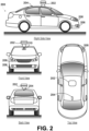
- FIG 2 depicts an example physical configuration of vehicle 200, which may represent one possible physical configuration of vehicle 100 described in reference to Figure 1 .
- vehicle 200 may include sensor unit 202, wireless communication system 204, radio unit 206, deflectors 208, and camera 210, among other possible components.
- vehicle 200 may include some or all of the elements of components described in Figure 1 .
- vehicle 200 is depicted in Figure 2 as a car, vehicle 200 can have other configurations within examples, such as a truck, a van, a semitrailer truck, a motorcycle, a golf cart, an off-road vehicle, or a farm vehicle, among other possible examples.
- Sensor unit 202 may include one or more sensors configured to capture information of the surrounding environment of vehicle 200.
- sensor unit 202 may include any combination of cameras, radars, LIDARs, range finders, radio devices (e.g., Bluetooth and/or 802.11), and acoustic sensors, among other possible types of sensors.
- sensor unit 202 may include one or more movable mounts operable to adjust the orientation of sensors in sensor unit 202.
- the movable mount may include a rotating platform that can scan sensors so as to obtain information from each direction around the vehicle 200.
- the movable mount of sensor unit 202 may also be moveable in a scanning fashion within a particular range of angles and/or azimuths.
- sensor unit 202 may include mechanical structures that enable sensor unit 202 to be mounted atop the roof of a car. Additionally, other mounting locations are possible within examples.
- Camera 210 may have various positions relative to vehicle 200, such as a location on a front windshield of vehicle 200. As such, camera 210 may capture images of the environment of vehicle 200. As illustrated in Figure 2 , camera 210 may capture images from a forward-looking (front-facing) view with respect to vehicle 200, but other mounting locations (including movable mounts) and viewing angles of camera 210 are possible within embodiments. For instance, camera 210 could be positioned within the vehicle so that the camera captures images of the environment of vehicle 200 through a windshield of vehicle 200.
- camera 210 may correspond to one or more visible light cameras. Alternatively or additionally, camera 210 may include infrared sensing capabilities. Camera 210 may also include optics that may provide an adjustable field of view. Other examples are also possible.
- FIG. 3 is a conceptual illustration of wireless communication between various computing systems related to an autonomous vehicle, according to example embodiments.
- wireless communication may occur between remote computing system 302 and vehicle 200 via network 304.
- Wireless communication may also occur between server computing system 306 and remote computing system 302, and between server computing system 306 and vehicle 200.
- Vehicle 200 can correspond to various types of vehicles capable of transporting passengers or objects between locations, and may take the form of any one or more of the vehicles discussed above.
- vehicle 200 may operate in an autonomous mode that enables a control system to safely navigate vehicle 200 between destinations using sensor measurements.
- vehicle 200 may navigate with or without passengers. As a result, vehicle 200 may pick up and drop off passengers between desired destinations.
- Remote computing system 302 may represent any type of device related to remote assistance techniques, including but not limited to those described herein.
- remote computing system 302 may represent any type of device configured to (i) receive information related to vehicle 200, (ii) provide an interface through which a human operator can in turn perceive the information and input a response related to the information, and (iii) transmit the response to vehicle 200 or to other devices.
- Remote computing system 302 may take various forms, such as a workstation, a desktop computer, a laptop, a tablet, a mobile phone (e.g., a smart phone), and/or a server.
- remote computing system 302 may include multiple computing devices operating together in a network configuration.
- Remote computing system 302 may include one or more subsystems and components similar or identical to the subsystems and components of vehicle 200. At a minimum, remote computing system 302 may include a processor configured for performing various operations described herein. In some embodiments, remote computing system 302 may also include a user interface that includes input/output devices, such as a touchscreen and a speaker. Other examples are possible as well.
- Network 304 represents infrastructure that enables wireless communication between remote computing system 302 and vehicle 200.
- Network 304 also enables wireless communication between server computing system 306 and remote computing system 302, and between server computing system 306 and vehicle 200.
- remote computing system 302 may have a remote position from vehicle 200 that has a wireless communication via network 304.
- remote computing system 302 may correspond to a computing device within vehicle 200 that is separate from vehicle 200, but with which a human operator can interact while a passenger or driver of vehicle 200.
- remote computing system 302 may be a computing device with a touchscreen operable by the passenger of vehicle 200.
- operations described herein that are performed by remote computing system 302 may be additionally or alternatively performed by vehicle 200 (i.e., by any system(s) or subsystem(s) of vehicle 200).
- vehicle 200 may be configured to provide a remote assistance mechanism with which a driver or passenger of the vehicle can interact.
- Server computing system 306 may be configured to wirelessly communicate with remote computing system 302 and vehicle 200 via network 304 (or perhaps directly with remote computing system 302 and/or vehicle 200).
- Server computing system 306 may represent any computing device configured to receive, store, determine, and/or send information relating to vehicle 200 and the remote assistance thereof.
- server computing system 306 may be configured to perform any operation(s), or portions of such operation(s), that is/are described herein as performed by remote computing system 302 and/or vehicle 200.
- Some embodiments of wireless communication related to remote assistance may utilize server computing system 306, while others may not.
- Server computing system 306 may include one or more subsystems and components similar or identical to the subsystems and components of remote computing system 302 and/or vehicle 200, such as a processor configured for performing various operations described herein, and a wireless communication interface for receiving information from, and providing information to, remote computing system 302 and vehicle 200.
- a computing system may operate to use a camera to capture images of the environment of an autonomous vehicle.
- at least one computing system will be able to analyze the images and possibly control the autonomous vehicle.
- a vehicle may receive data representing objects in an environment in which the vehicle operates (also referred to herein as "environment data") in a variety of ways.
- a sensor system on the vehicle may provide the environment data representing objects of the environment.
- the vehicle may have various sensors, including a camera, a radar unit, a laser range finder, a microphone, a radio unit, and other sensors. Each of these sensors may communicate environment data to a processor in the vehicle about information each respective sensor receives.
- a camera may be configured to capture still images and/or video.
- the vehicle may have more than one camera positioned in different orientations.
- the camera may be able to move to capture images and/or video in different directions.
- the camera may be configured to store captured images and video to a memory for later processing by a processing system of the vehicle.
- the captured images and/or video may be the environment data.
- the camera may include an image sensor as described herein.
- a radar unit may be configured to transmit an electromagnetic signal that will be reflected by various objects near the vehicle, and then capture electromagnetic signals that reflect off the objects.
- the captured reflected electromagnetic signals may enable the radar system (or processing system) to make various determinations about objects that reflected the electromagnetic signal. For example, the distance and position to various reflecting objects may be determined.
- the vehicle may have more than one radar in different orientations.
- the radar system may be configured to store captured information to a memory for later processing by a processing system of the vehicle.
- the information captured by the radar system may be environment data.
- a laser range finder may be configured to transmit an electromagnetic signal (e.g., light, such as that from a gas or diode laser, or other possible light source) that will be reflected by a target objects near the vehicle.
- the laser range finder may be able to capture the reflected electromagnetic (e.g., laser) signals.
- the captured reflected electromagnetic signals may enable the range-finding system (or processing system) to determine a range to various objects.
- the range-finding system may also be able to determine a velocity or speed of target objects and store it as environment data.
- a microphone may be configured to capture audio of environment surrounding the vehicle. Sounds captured by the microphone may include emergency vehicle sirens and the sounds of other vehicles. For example, the microphone may capture the sound of the siren of an emergency vehicle. A processing system may be able to identify that the captured audio signal is indicative of an emergency vehicle. In another example, the microphone may capture the sound of an exhaust of another vehicle, such as that from a motorcycle. A processing system may be able to identify that the captured audio signal is indicative of a motorcycle. The data captured by the microphone may form a portion of the environment data.
- the radio unit may be configured to transmit an electromagnetic signal that may take the form of a Bluetooth signal, 802.11 signal, and/or other radio technology signal.
- the first electromagnetic radiation signal may be transmitted via one or more antennas located in a radio unit. Further, the first electromagnetic radiation signal may be transmitted with one of many different radio-signaling modes. However, in some embodiments it is desirable to transmit the first electromagnetic radiation signal with a signaling mode that requests a response from devices located near the autonomous vehicle.
- the processing system may be able to detect nearby devices based on the responses communicated back to the radio unit and use this communicated information as a portion of the environment data.
- the processing system may be able to combine information from the various sensors in order to make further determinations of the environment of the vehicle. For example, the processing system may combine data from both radar information and a captured image to determine if another vehicle or pedestrian is in front of the autonomous vehicle. In other embodiments, other combinations of sensor data may be used by the processing system to make determinations about the environment.
- the vehicle While operating in an autonomous mode, the vehicle may control its operation with little-to-no human input. For example, a human-operator may enter an address into the vehicle and the vehicle may then be able to drive, without further input from the human (e.g., the human does not have to steer or touch the brake/gas pedals), to the specified destination. Further, while the vehicle is operating autonomously, the sensor system may be receiving environment data. The processing system of the vehicle may alter the control of the vehicle based on environment data received from the various sensors. In some examples, the vehicle may alter a velocity of the vehicle in response to environment data from the various sensors. The vehicle may change velocity in order to avoid obstacles, obey traffic laws, etc. When a processing system in the vehicle identifies objects near the vehicle, the vehicle may be able to change velocity, or alter the movement in another way.
- a human-operator may enter an address into the vehicle and the vehicle may then be able to drive, without further input from the human (e.g., the human does not have to steer or touch the brake
- the vehicle can request a human operator (or a more powerful computer) to perform one or more remote assistance tasks, such as (i) confirm whether the object is in fact present in the environment (e.g., if there is actually a stop sign or if there is actually no stop sign present), (ii) confirm whether the vehicle's identification of the object is correct, (iii) correct the identification if the identification was incorrect and/or (iv) provide a supplemental instruction (or modify a present instruction) for the autonomous vehicle.
- a human operator or a more powerful computer
- Remote assistance tasks may also include the human operator providing an instruction to control operation of the vehicle (e.g., instruct the vehicle to stop at a stop sign if the human operator determines that the object is a stop sign), although in some scenarios, the vehicle itself may control its own operation based on the human operator's feedback related to the identification of the object.
- the human operator providing an instruction to control operation of the vehicle (e.g., instruct the vehicle to stop at a stop sign if the human operator determines that the object is a stop sign), although in some scenarios, the vehicle itself may control its own operation based on the human operator's feedback related to the identification of the object.
- the vehicle may analyze the environment data representing objects of the environment to determine at least one object having a detection confidence below a threshold.
- a processor in the vehicle may be configured to detect various objects of the environment based on environment data from various sensors.
- the processor may be configured to detect objects that may be important for the vehicle to recognize.
- objects may include pedestrians, street signs, other vehicles, indicator signals on other vehicles, and other various objects detected in the captured environment data.
- the detection confidence may be indicative of a likelihood that the determined object is correctly identified in the environment, or is present in the environment.
- the processor may perform object detection of objects within image data in the received environment data, and determine that the at least one object has the detection confidence below the threshold based on being unable to identify the object with a detection confidence above the threshold. If a result of an object detection or object recognition of the object is inconclusive, then the detection confidence may be low or below the set threshold.
- the vehicle may detect objects of the environment in various way depending on the source of the environment data.
- the environment data may come from a camera and be image or video data.
- the environment data may come from a LIDAR unit.
- the vehicle may analyze the captured image or video data to identify objects in the image or video data.
- the methods and apparatuses may be configured to monitor image and/or video data for the presence of objects of the environment.
- the environment data may be radar, audio, or other data.
- the vehicle may be configured to identify objects of the environment based on the radar, audio, or other data.
- the techniques the vehicle uses to detect objects may be based on a set of known data. For example, data related to environmental objects may be stored to a memory located in the vehicle. The vehicle may compare received data to the stored data to determine objects. In other embodiments, the vehicle may be configured to determine objects based on the context of the data. For example, street signs related to construction may generally have an orange color. Accordingly, the vehicle may be configured to detect objects that are orange, and located near the side of roadways as construction-related street signs. Additionally, when the processing system of the vehicle detects objects in the captured data, it also may calculate a confidence for each object.
- the vehicle may also have a confidence threshold.
- the confidence threshold may vary depending on the type of object being detected. For example, the confidence threshold may be lower for an object that may require a quick responsive action from the vehicle, such as brake lights on another vehicle. However, in other embodiments, the confidence threshold may be the same for all detected objects. When the confidence associated with a detected object is greater than the confidence threshold, the vehicle may assume the object was correctly recognized and responsively adjust the control of the vehicle based on that assumption.
- the actions that the vehicle takes may vary. In some embodiments, the vehicle may react as if the detected object is present despite the low confidence level. In other embodiments, the vehicle may react as if the detected object is not present.
- the vehicle When the vehicle detects an object of the environment, it may also calculate a confidence associated with the specific detected object.
- the confidence may be calculated in various ways depending on the embodiment. In one example, when detecting objects of the environment, the vehicle may compare environment data to predetermined data relating to known objects. The closer the match between the environment data to the predetermined data, the higher the confidence. In other embodiments, the vehicle may use mathematical analysis of the environment data to determine the confidence associated with the objects.
- the vehicle may transmit, to the remote computing system, a request for remote assistance with the identification of the object.
- the remote computing system may take various forms.
- the remote computing system may be a computing device within the vehicle that is separate from the vehicle, but with which a human operator can interact while a passenger or driver of the vehicle, such as a touchscreen interface for displaying remote assistance information.
- the remote computing system may be a remote computer terminal or other device that is located at a location that is not near the vehicle.
- first image sensor 410 and the second image sensor 420 may be aligned horizontally (e.g., again ensuring that the orientation of the objects within the scene 402 may be the same or approximately the same for an image captured by the first image sensor 410 as for an image captured by the second image sensor 420).
- Such apertures may be adjusted to control the amount of light from the scene 402 reaching a respective image sensor, modify the depth of field for a respective image sensor, and/or modify the range of viable exposure durations based on light reaching a respective image sensor for a given image being captured by a respective image sensor.
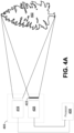
- the first image sensor 410 may be adjusted based on the composite luminance level of the scene 402 (fixed value based on the scene). For example, the first image sensor 410 may sense an illuminance value on the first image sensor 410, and transmit the illuminance value to a controller of the first image sensor 410. Based on the illuminance value, the controller may modify exposure settings corresponding to the first image sensor 410 (e.g., exposure duration / shutter speed, aperture size, focal length of one or more lenses, ISO sensitivity of the image sensor, etc.) until the illuminance value on the first image sensor 410 (modifiable value based on exposure settings) is within a threshold acceptable range.
- exposure settings corresponding to the first image sensor 410 e.g., exposure duration / shutter speed, aperture size, focal length of one or more lenses, ISO sensitivity of the image sensor, etc.
- the first image sensor 410 has a variable exposure that is adjusted by a controller based on illuminance value. This may be analogous to an "automatic exposure" setting in some cameras (e.g., a digital single-lens reflex (DSLR) camera).
- DSLR digital single-lens reflex
- the second image sensor 420 may also modify exposure settings corresponding to the second image sensor 420 until the illuminance value on the second image sensor 420 is within a threshold acceptable range. In alternative embodiments, however, the second image sensor 420 may have fixed exposure settings. Because the second image sensor 420 receives light from the scene 402 via the neutral-density filter 422, if the second image sensor 420 is not adjusted based on illuminance value, the second image sensor 420 may capture images of the scene 402 at a lower overall intensity.
- Capturing images via the neutral-density filter 422 without compensating for the neutral-density filter 422 by modifying exposure settings can allow bright objects (e.g., an actively illuminated object like an emergency signal on an ambulance) to be observed without being overexposed. Additionally, capturing images at a lower overall intensity may reduce stray light, glare, and flare artifacts within the captured images.
- the second image sensor 420 includes a neutral-density filter 422 and the first image sensor 410 does not, and the second image sensor 420 might not compensate exposure settings when a lower illuminance value is present whereas the first image sensor 410 may, the first image sensor 410 and the second image sensor 420 may each have a corresponding (possibly different) dynamic range.
- a first dynamic range 414 may correspond to the first image sensor 410 and a second dynamic range 424 may correspond to the second image sensor 420.
- Each of the dynamic ranges 414/424 may correspond to a range of luminance levels within the scene 402 (illustrated in Figure 4B using a logarithmic scale for luminance). As illustrated in Figure 4B , the second dynamic range 424 may correspond to a higher range of luminance levels than the first dynamic range 414. As such, the second image sensor 420 may be used to detect/identify objects having a higher luminance than the first image sensor 410. For example, an image captured by the second image sensor 420 may be used to identify a traffic light whereas an image captured by the first image sensor 410 may be used to identify a pedestrian.
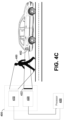
- an image captured by the second image sensor 420 may be used to identify tail lights 452 (or other actively illuminated object) of a vehicle and an image captured by the first image sensor 410 may be used to identify a pedestrian 450 crossing the street (or other passively illuminated object).
- a pedestrian 450 may be crossing the street between the camera system 400 and the vehicle with the tail lights 452, for example.
- the first image sensor 410 may adjust its exposure settings based on illuminance values sensed by the first image sensor 410, the corresponding first dynamic range 414 may be varied to encompass higher or lower luminance values.
- the second dynamic range 424 may include one or more luminance levels that are higher than the first dynamic range 414. As illustrated, at least a portion of the luminance levels of the first dynamic range 414 may overlap a portion of the luminance levels of the second dynamic range 424.
- the first dynamic range 414 may not overlap the second dynamic range 424 (e.g., every luminance level in the first dynamic range 414 may be lower than every luminance level in the second dynamic range 424).
- a portion or the entirety of the first dynamic range 414 may include luminance levels that are higher than all of the luminance levels in the second dynamic range 424.
- HDR imaging approaches In some alternative high-dynamic-range (HDR) imaging approaches, a continuum of luminance levels is used to generate a complete, composite image (e.g., HDR imaging approaches that use a single image sensor). However, some alternative HDR imaging approaches do not allow for a gap in the dynamic range. Thus, in embodiments where there is a range of luminance levels that contain objects that do not need to be observed/detected, those luminance levels can be skipped over. This can save on data storage and computation time, for example, when compared to HDR imaging approaches that do not allow for a gap in the dynamic range. Alternatively, in some embodiments disclosed herein, the first dynamic range 414 may entirely encompass the second dynamic range 424 or vice versa.
- the collective dynamic range spanned by the camera system 400 (including the first dynamic range 414 and the second dynamic range 424) is larger than either of the first dynamic range 414 or the second dynamic range 424, individually.
- Using a technique such as described above can effectively expand the dynamic range of a camera without necessarily modifying the image sensors themselves. Because the image sensors do not necessarily need to be modified, such a technique can lead to improved dynamic range without the need for specialized (and potentially expensive) cameras/image sensors.
- each of the first image sensor 410 and the second image sensor 420 may be connected to a processor 430 (e.g., analogous to the processor 113 illustrated in Figure 1 ).
- the processor 430 may be a part of a computing device (e.g., the computer system 112 illustrated in Figure 1 ) that executes instructions (e.g., the instructions 115 illustrated in Figure 1 ) stored on a memory (e.g., the data storage 114 illustrated in Figure 1 ).
- the processor 430 may receive a first captured image from the first image sensor 410 and/or a second captured image from the second sensor 420.
- the processor 430 may only attempt to identify actively illuminated objects (e.g., tail lights, traffic lights, etc.) using images captured by the second image sensor 420 and may only attempt to identify passively illuminated objects (e.g., objects illuminated by reflecting or refracting light, such as pedestrians, trees, stop signs, etc.) using images captured by the first image sensor 410.
- actively illuminated objects e.g., tail lights, traffic lights, etc.
- passively illuminated objects e.g., objects illuminated by reflecting or refracting light, such as pedestrians, trees, stop signs, etc.
- the processor 430 may only attempt to identify objects at motion relative to the camera system 400 that have a high velocity relative to the shutter speed / exposure duration of the first image sensor 410 within an image captured by the first image sensor 4 10 (e.g., weather effects, such as rain). Still further, in order to save computation time, the processor 430 may only attempt to identify actively illuminated objects that are modulated at faster rates than the shutter speed / exposure duration of the first image sensor 410 within an image captured by the first image sensor 410 (e.g., construction signs).
- the processor 430 may only attempt to identify objects at motion relative to the camera system that have a low velocity or comparable velocity relative to the shutter speed / exposure duration of the first image sensor 410 within an image captured by the second image sensor 420 (e.g., pedestrians). Still further, in order to save computation time, the processor 430 may only attempt to identify actively illuminated objects that are modulated at similar or slower rates than the shutter speed / exposure duration of the first image sensor 410 within an image captured by the second image sensor 420 (e.g., flashing turn signals).
- the hardware of a given image sensor may be specialized for a given range of luminance levels and/or variations over time.
- the second image sensor 420 may have hardware specialized for detecting passively illuminated objects (e.g., specialized hardware in addition to the neutral-density filter 422, such as different lenses than the first image sensor 410, one or more additional filters compared to the first image sensor 410, etc.).
- the first image sensor 410 and the second image sensor 420 may compress the captured images. Additionally or alternatively, the computing device may compress the captured images after receiving them from the first image sensor 4 10 and the second image sensor 420.
- object-identification algorithms e.g., instructions stored within a memory executable by a processor to identify objects within an image
- the object-identification algorithms may be optimized for HDR, 24-bit images (i.e., HDR images that represent each pixel by an 8-bit number for each of the following colors: red, green, and blue).
- images captured by the first image sensor 410 and the second image sensor 420 are each 24-bit images
- images captured by the first image sensor 410 and the second image sensor 420 may be combined into a single HDR, 24-bit image such that the combined image may be processed by one of the object-identification algorithms optimized for HDR, 24-bit images.
- the object-identification algorithm may instead be optimized for other types of images (e.g., 30-bit images, 36-bit images, 42-bit images, 48-bit images, etc.).
- Combining the two captured images into a single HDR, 24-bit image may include performing tone mapping (i.e., remapping the color sets in each of the individual captured images to a new global color set in the combined image in order to approximate HDR). While this can allow for the use of an expanded library of object-identification algorithms (e.g., object-identification algorithms that are optimized for HDR, 24-bit images), the tone mapping may sacrifice inherent data about physical luminance levels and global contrast contained across the individual images captured by the first image sensor 410 and the second image sensor 420.
- tone mapping i.e., remapping the color sets in each of the individual captured images to a new global color set in the combined image in order to approximate HDR. While this can allow for the use of an expanded library of object-identification algorithms (e.g., object-identification algorithms that are optimized for HDR, 24-bit images), the tone mapping may sacrifice inherent data about physical luminance levels and global contrast contained across the individual images captured by the first image sensor 410 and the second image sensor 420.
- each of the individual images may be fed into separate object-identification algorithms (e.g., executable by a processor and stored within a memory).
- object-identification algorithms may themselves be jointly and/or individually optimized for a given dynamic range (e.g., given range of luminance levels).
- each of the individual images may be fed into a single, combined object-identification algorithm that is designed to handle both images jointly.
- the combined object-identification algorithm may be a machine-learned algorithm, such as a convolutional neural network.
- the convolutional neural network may treat the combined images as if they have six colors, as opposed to the canonical three colors (red, green, blue).
- the convolutional neural network may interpret the six color channels using an intermediate neuron layer that tracks more than three color values (e.g., six color values) per pixel, for example.
- a processor may perform object identification of an object using both captured images, as opposed to using only a single captured image.
- an emergency vehicle at night may include both high luminance levels (e.g., the emergency lights of the emergency vehicle) and low luminance levels (e.g., the tires or the painted body of the emergency vehicle).
- portions of both the image captured by the first image sensor 410 and the image captured by the second image sensor 420 may be used to identify the object as an ambulance, fire truck, or a police vehicle.
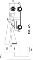
- Figure 4D Such an embodiment is illustrated in Figure 4D .
- the second image sensor 420 may be directed toward lights 460 of an emergency vehicle (e.g., an ambulance) and the first image sensor 410 may be directed toward the painted body 462 of the emergency vehicle (e.g., red stripes on an emergency vehicle, a red checkered pattern on an emergency vehicle, or a red cross on an emergency vehicle).
- the emergency vehicle can be identified. For example, an identified combination of body paint that includes a red cross in a first image and red and white emergency lights in a second image may indicate that the identified object is an emergency vehicle (e.g., an ambulance). Further, based on whether the red and white emergency lights are flashing for example, it may be determined whether the emergency vehicle is en route to/from an active emergency.
- the first image sensor 410 and the second image sensor 420 may be offset with respect to one another by a distance (e.g., vertically offset by a distance in Figure 4A ).
- the first image sensor 410 may be above, below, to the left, to the right, in front, behind, or some superposition of above, below, to the left, to the right, in front, and behind of the second image sensor 420 with respect to the scene 402.
- a processor connected to the camera system 400 may be configured to perform binocular distance calculations, regardless of whether an object can be properly identified in an image captured by the first image sensor 410 or in an image captured by the second image sensor 420.
- the distance may be determined by a processor executing instructions in order to calculate the parallax between the location of an object within an image captured by the first image sensor 410 and the location of an object within an image captured by the second image sensor 420 (taking into account a known offset distance between the first image sensor 410 and the second image sensor 420).
- a more conventional method of capturing two images, with separate dynamic ranges, of the same scene includes using a camera with only a single image sensor (rather than two image sensors).
- a camera with a single image sensor an image may be captured of a scene at a first dynamic range (e.g., depending on exposure settings such as ISO, sensor sensitivity, exposure duration / shutter speed, aperture size, etc.).
- the exposure settings of the single image sensor may be changed (e.g., by modifying the shutter speed / exposure duration or aperture size), and a second image of the scene at a second dynamic range may be captured.
- the two images may not be captured substantially simultaneously.
- the perspective of the scene may have substantially changed between capturing both of the images. While this may be acceptable for stationary scenes (e.g., portraits), this can create issues for moving scenes.
- the perspective may be substantially different between image capture events (e.g., if the moving vehicle is moving at 50 mph, 50 ms corresponds to a translation of 1.1 m, which may be non-negligible).
- the images of a scene are not captured substantially simultaneously by a single image sensor that is modifying exposure settings between image capturing events, the images of the scene also might not be transmitted to a computing device performing object analysis substantially simultaneously.
- This can be problematic if the camera of the single image sensor only has enough onboard memory to locally store one captured image at a time.
- the processor of the computing device could process each of the captured images sequentially, or the camera could reduce the resolution of the captured image so that it can store two images within its local memory and then transmit both images to the computing device.
- this also may give rise to a problem, because a significant lag between when the first image is captured, and when the computing device is performing image analysis on the first image may be present.
- the computing device is processing the first image captured, it may be too late to make meaningful control decisions based on the captured first image.
- Figure 5 illustrates a camera system 500, according to example embodiments.
- the camera system 500 may include an image sensor 510, a neutral-density filter 522, a first lens 514, and a second lens 524.
- the first lens 514 may direct a field of view of the scene 402 to a first independent region of the image sensor 510.
- the second lens 524 may direct a field of view of the scene 402 to a second independent region of the image sensor 510.
- the second lens 524 as illustrated, may direct a field of view of the scene 402 to the second independent region of the image sensor through the neutral-density filter 522.
- the camera system 500 may also include a processor (e.g., analogous to the processor 430 illustrated in Figure 4A ) that is communicatively coupled to the image sensor 510 and configured to perform object recognition (e.g., by executing instructions stored within a memory).
- a processor e.g., analogous to the processor 430 illustrated in Figure 4A
- object recognition e.g., by executing instructions stored within a memory
- the image sensor 510 may have a variable exposure across both independent sensor regions.
- the variable exposure may be controlled by a controller by adjusting various exposure settings (e.g., exposure duration, ISO sensitivity, etc.) based on a composite illuminance sensed by both independent sensor regions (e.g., based on an average of the illuminance of the first sensor region and the illuminance of the second sensor region).
- the exposure settings across both independent sensor regions may be fixed.
- the exposure settings of both independent sensor regions may be individually controllable.
- the upper independent sensor region may have its sensitivity adjusted by a controller based on the illuminance sensed on the upper independent sensor region, whereas the lower independent sensor region may have fixed exposure settings regardless of illuminance sensed on the lower independent sensor region.
- a single image sensor can be used to capture a composite image.
- the composite image may include multiple regions, each region containing an entire reproduction of the scene 402 with a given field of view and perspective.
- the field of view and perspective may be the same for each region.
- each of the regions of the composite image may be captured with different illuminance. In this way, different regions of the captured image may be analyzed to identify objects within different dynamic ranges.
- the upper region of a corresponding captured composite image may be used to identify objects (e.g., by a processor executing an object-identification algorithm) having lower relative luminance values (e.g., passively illuminated objects), whereas the lower region of a corresponding captured composite image may be used to identify objects (e.g., by a processor executing an object identification algorithm) having higher relative luminance values (e.g., actively illuminated objects).
- the independent sensor regions may be arranged on left and right, rather than top and bottom. In still other embodiments, there may be more than two independent sensor regions. For example, in one embodiment, there may be four independent sensor regions: one independent sensor region without a neutral-density filter, one independent sensor region covered by one neutral-density filter (e.g., an ND8 neutral-density filter), one independent sensor region covered by another neutral-density filter (e.g. an ND128 neutral-density filter), and one independent sensor region covered by yet another neutral-density filter (e.g., an ND4096 neutral-density filter).
- one neutral-density filter e.g., an ND8 neutral-density filter
- another neutral-density filter e.g. an ND128 neutral-density filter
- yet another neutral-density filter e.g., an ND4096 neutral-density filter
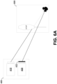
- Figure 6A is an illustration of a camera system 400, according to example embodiments.
- the camera system 400 may be the same camera system 400 illustrated in Figure 4A , for example.
- the camera system 400 is being used to capture images of a scene 600.
- the first image sensor 410 and the second image sensor 420 may be vertically offset from one another by some distance. As such, the perspective of the first image sensor 410 relative to the scene 600 may be different than the perspective of the second image sensor 420 relative to the scene 600.
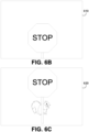
- a first image 610 of the scene 600 captured by the first image sensor 410 is illustrated in Figure 6B .
- a second image 620 of the scene 600 captured by the second image sensor 420 is illustrated in Figure 6C .
- some objects in the scene 600 may not be observable from all perspectives.
- the squirrel in the scene 600 is not observable by the first image sensor 410, but is observable by the second image sensor 420.
- images captured by both image sensors can be used to identify the object (e.g., by an object identification algorithm executed by a processor), if the object is present within a respective perspective of the scene 600 for a respective image sensor 410/420.
- the object identification may include error correction and redundancy.
- two image sensors each at a different perspective relative to a scene can be used to correct for stray light and scatter due to artifacts within the scene. If a bright object, such as the sun, is directly behind an object to be identified, that object might be blown out, overexposed, distorted, or saturated in one of the two images captured by the first image sensor 410 and the second image sensor 420, respectively, due to the presence of the sun.
- the processor executing the instructions may extract regions from an image captured by the second image sensor 720 that correspond to objects in the background of the scene 402, because the second lens 724 has a longer focal length than the first lens 714. The processor executing the instructions may then combine these regions into a single composite image that represents multiple focal lengths.
- the forward-facing camera sub-system 400A may receive light from a first perspective 902 of a scene and the backward-facing camera sub-system 400B may receive light from a second perspective 904 of the same scene.
- the camera system 900 may also include a processor (e.g., analogous to the processor 430 illustrated in Figure 4A ) that is communicatively coupled to the image sensors in the first camera sub-system 400A and/or the second camera sub-system 400B and configured to perform object recognition (e.g., by executing instructions stored within a memory).
- the first perspective 902 and the second perspective 904 may include different objects than one another (e.g., the first perspective 902 may contain a tree while the second perspective 904 contains a stop sign). Additionally or alternatively, the first perspective 902 may contain actively illuminated objects and/or passively illuminated objects. Similarly, the second perspective 904 may contain actively illuminated objects and/or passively illuminated objects.
- objects in multiple directions relative to the vehicle 200 i.e., multiple perspectives based on the field of view of each of the image sensors of the camera system 900 may be captured and identified.
- the first image sensor 410A/410B and the second image sensor 420A/420B in each of the camera sub-systems 400A/400B may be aligned vertically with one another.
- the first image sensor 410A/410B and the second image sensor 420A/420B may be aligned differently and/or at different distances with respect to one another across the plurality of camera sub-systems 400A/400B within the camera system 900.
- Images captured by each image sensor 410A/410B/420A/420B from each of the camera sub-systems 400A/400B may be transmitted to a single computing device (e.g., including a processor configured to execute instructions stored within a memory to perform object identification).
- images captured by each image sensor 410A/410B/420A/420B from respective camera sub-systems 400A/400B may be transmitted to independent, respective computing devices.
- the computing device(s) may attempt to save computation time (e.g., based on object-recognition instructions executed by a processor and stored within a memory) by only searching for objects of a first type in images captured by the first image sensors 410A/410B and only searching for objects of a second type in images captured by the second image sensors 420A/420B.
- computation time e.g., based on object-recognition instructions executed by a processor and stored within a memory
- the first type of objects may include actively illuminated objects having a slow or comparable modulation time when compared with shutter speeds / exposure durations of the first image sensors 410A/410B and the second image sensors 420A/420B, passively illuminated objects, objects moving at high velocities relative to the shutter speeds / exposure durations of the first image sensors 410A/410B and the second image sensors 420A/420B, or objects having a low luminance when compared to the rest of the scene.
- the second type of objects may include actively illuminated objects having a fast modulation time when compared with shutter speeds / exposure durations of the first image sensors 410A/410B and the second image sensors 420A/420B, objects moving at slow or comparable velocities relative to the shutter speeds / exposure durations of the first image sensors 410A/410B and the second image sensors 420A/420B, or objects having a high luminance when compared to the rest of the scene.
- Figure 9B illustrates an alternative camera system 910 that includes a plurality of camera sub-systems (each camera sub-system including respective image sensors).
- the camera system 910 may be mounted on a vehicle and images captured by the image sensors of the camera system 910 may be used for object identification and avoidance and/or for navigation.
- a potential direction of travel of a corresponding vehicle is illustrated in Figure 9B by a dashed arrow.
- Figure 9B is a top view of the camera system 910.
- the camera system 910 illustrated includes eight camera systems 400 as illustrated in Figure 4A , spaced around the periphery of the camera system 910 by angles of between 30° and 60°, for example.
- the dashed lines in Figure 9B illustrate possible fields of view for the image sensors in the respective camera systems 400.
- the image sensors in the camera systems 400 may have fields of view of between 80° and 100°. Thus, the fields of view of the camera systems 400 may overlap.
- camera systems, and corresponding image sensors may be assembled in a ring formation.
- the ring formation may be designed such that the angle and orientation of each individual camera system, and corresponding image sensors, is positioned correctly to eliminate blind spots.
- the camera systems may work together to form a cohesive, circular vision of the surrounding scene.
- the fields of view for each of the camera systems 400 may be different (e.g., 15°, 30°, 45°, 60°, 75°, 105°, 120°, 135°, 150°, 165°, 180°, 195°, 210°, 225°, 240°, 255°, 270°, 285°, 300°, 315°, 330°, 345°, or 360°).
- the camera systems, and corresponding image sensors may be assembled in non-ring formations (e.g., with camera systems at the corners of a vehicle's roof).
- multiple types of camera systems may be used (e.g., rather than eight instances of a single type of camera system).
- the different camera systems may each have different corresponding fields of view.
- a minimum number of camera systems 400 may be used to span the periphery of the vehicle. For example, if the camera systems 400 used are all the same as one another, as in Figure 9B , and each includes image sensors that have a field of view between 80° and 100°, only four camera systems may be included in the camera system 910 (e.g., 360° divided by 90° corresponds to four camera systems).
- one example camera system 920 may include additional image sensors on the front-facing portion of the camera system 920.
- the three front-facing camera sub-systems may each be the camera system 800 illustrated in Figure 8A .
- the camera systems 800 include three image sensors, one of which may be configured to sense low-luminance objects (e.g., a black cat on at night). In this way, the object detection and avoidance capabilities of the camera system 920 illustrated in Figure 9C may be improved when compared with the camera system 910 illustrated in Figure 9B .
- the front-facing portion of the camera system 930 includes additional camera sub-systems (e.g., at angles of between 20° and 25° and between -20° and -25°, in addition to at angles between 40° and 50° and between -40° and -50°, relative to the direction of travel) when compared with the camera systems 910, 920 illustrated in Figures 9B and 9C .
- the front-facing camera sub-systems may include low-light image sensors (e.g., the third image sensor 830 in the camera system 800 illustrated in Figure 8A ).
- additional camera systems 400 as illustrated in Figure 4A and/or other additional camera systems may be included in the camera system 930.
- Figure 10 is a flowchart diagram of a method 1000, according to example embodiments.
- the method 1000 may be used to detect and/or avoid one or more objects within the environment of an autonomous vehicle using an image sensing system, for example.
- the method 1000 may be performed using the camera system 400 illustrated in Figure 4A , for example. In alternate embodiments, the method 1000 may be performed using alternate camera systems.
- the method 1000 includes capturing, by a first image sensor having a first dynamic range corresponding to a first range of luminance levels in a scene, a first image of the scene.
- the method 1000 includes capturing, by a second image sensor having a second dynamic range corresponding to a second range of luminance levels in the scene, a second image of the scene.
- the second image sensor captures the second image of the scene via a neutral-density filter.
- the second range of luminance levels includes luminance levels that are higher than the first range of luminance levels.
- the method 1000 includes identifying, by a processor coupled to the first image sensor and the second image sensor, a first object of a first object type in the first image.
- the first object type has an expected luminance within the first range of luminance levels.
- the method 1000 includes identifying, by the processor, a second object of a second object type in the second image.
- the second object type has an expected luminance within the second range of luminance levels.
Landscapes
- Engineering & Computer Science (AREA)
- Multimedia (AREA)
- Signal Processing (AREA)
- Theoretical Computer Science (AREA)
- Human Computer Interaction (AREA)
- General Physics & Mathematics (AREA)
- Physics & Mathematics (AREA)
- Medical Informatics (AREA)
- Computing Systems (AREA)
- Databases & Information Systems (AREA)
- Evolutionary Computation (AREA)
- General Health & Medical Sciences (AREA)
- Computer Vision & Pattern Recognition (AREA)
- Software Systems (AREA)
- Artificial Intelligence (AREA)
- Health & Medical Sciences (AREA)
- Mechanical Engineering (AREA)
- Traffic Control Systems (AREA)
- Studio Devices (AREA)
- Transforming Light Signals Into Electric Signals (AREA)
- Exposure Control For Cameras (AREA)
- User Interface Of Digital Computer (AREA)
- Transition And Organic Metals Composition Catalysts For Addition Polymerization (AREA)
- Medicines Containing Antibodies Or Antigens For Use As Internal Diagnostic Agents (AREA)
- Steroid Compounds (AREA)
Claims (14)
- Kamerasystem, umfassend:einen ersten Bildsensor (410; 710), der einen ersten Dynamikbereich aufweist, der einem ersten Bereich von Luminanzpegeln in einer Szene entspricht;einen zweiten Bildsensor (420; 720), der einen zweiten Dynamikbereich aufweist, der einem zweiten Bereich von Luminanzpegeln in der Szene entspricht, wobei der zweite Bildsensor Licht von der Szene über ein Neutraldichtefilter (422; 722) empfängt, und wobei der zweite Bereich von Luminanzpegeln Luminanzpegel beinhaltet, die höher als der erste Bereich von Luminanzpegeln sind; undeinen Prozessor, der mit dem ersten Bildsensor und dem zweiten Bildsensor gekoppelt ist, dadurch gekennzeichnet, dass der Prozessor konfiguriert ist, Anweisungen auszuführen, um:Objekte eines ersten Objekttyps in einem ersten Bild der Szene, das durch den ersten Bildsensor erfasst wird, zu identifizieren, wobei der erste Objekttyp eine erwartete Luminanz innerhalb des ersten Bereichs von Luminanzpegeln aufweist; undObjekte eines zweiten Objekttyps in einem zweiten Bild der Szene, das durch den zweiten Bildsensor erfasst wird, zu identifizieren, wobei der zweite Objekttyp eine erwartete Luminanz innerhalb des zweiten Bereichs von Luminanzpegeln aufweist;wobei der erste Bildsensor eine variable Belichtungseinstellung aufweist, die basierend auf einer Helligkeit der Szene verändert wird, undwobei der zweite Bildsensor eine feste Belichtungseinstellung aufweist, die unabhängig von der Helligkeit der Szene nicht variiert.
- Kamerasystem nach Anspruch 1, wobei das Anpassen der variablen Belichtung basierend auf der Luminanz ein Anpassen einer Belichtungsdauer, einer Blendengröße, eines Verstärkungsgrads oder einer ISO-Empfindlichkeit des ersten Bildsensors umfasst.
- Kamerasystem nach Anspruch 1,wobei die variable Belichtung durch Modifizieren einer Verschlusszeit eines Verschlusses an dem ersten Bildsensor oder eines Verstärkungsgrads des ersten Bildsensors angepasst wird,wobei der erste Objekttyp Folgendes umfasst:Objekte, die sich in Bezug auf das Kamerasystem bewegen und hohe Geschwindigkeiten in Bezug auf die Verschlusszeit aufweisen; oderaktiv beleuchtete Objekte, die durch Licht beleuchtet werden, das mit einer schnelleren Rate als die Verschlusszeit moduliert wird, undwobei der zweite Objekttyp Folgendes umfasst:Objekte, die sich in Bezug auf das Kamerasystem bewegen und geringe Geschwindigkeiten oder vergleichbare Geschwindigkeiten in Bezug auf die Verschlusszeit aufweisen; oderaktiv beleuchtete Objekte, die durch Licht beleuchtet werden, das mit einer ähnlichen oder langsameren Rate als die Verschlusszeit moduliert wird.
- Kamerasystem nach Anspruch 1, ferner umfassend einen dritten Bildsensor, der einen dritten Dynamikbereich aufweist, der einem dritten Bereich von Luminanzpegeln in der Szene entspricht,wobei der Prozessor mit dem dritten Bildsensor gekoppelt ist,wobei der dritte Bereich von Luminanzpegeln zumindest einen Luminanzpegel beinhaltet, der niedriger als der erste Bereich von Luminanzpegeln ist, undwobei der Prozessor ferner konfiguriert ist, Anweisungen auszuführen, um Objekte eines dritten Objekttyps in einem dritten Bild der Szene zu identifizieren, das durch den dritten Bildsensor erfasst wird,wobei der dritte Objekttyp eine erwartete Luminanz innerhalb des dritten Bereichs von Luminanzpegeln aufweist.
- Kamerasystem nach Anspruch 4,wobei der dritte Bildsensor eine variable Belichtung aufweist, die durch eine Steuerung angepasst wird, die Anweisungen basierend auf Beleuchtungsstärke ausführt;wobei das Anpassen der variablen Belichtung basierend auf der Luminanz optional ein Anpassen einer Belichtungsdauer, einer Verschlusszeit, einer Blendengröße oder einer ISO-Empfindlichkeit des dritten Bildsensors umfasst.
- Kamerasystem nach Anspruch 1, ferner umfassend:einen dritten Bildsensor, der den ersten Dynamikbereich aufweist; undeinen vierten Bildsensor, der den zweiten Dynamikbereich aufweist,wobei der vierte Bildsensor Licht von einer separaten Perspektive der Szene über einen zusätzlichen Neutraldichtefilter empfängt,wobei der Prozessor mit dem dritten Bildsensor und dem vierten Bildsensor gekoppelt ist, undwobei der Prozessor ferner konfiguriert ist, Anweisungen auszuführen zum:Identifizieren von Objekten des ersten Objekttyps in einem dritten Bild der separaten Perspektive der Szene, das durch den dritten Bildsensor erfasst wird; undIdentifizieren von Objekten des zweiten Objekttyps in einem vierten Bild der separaten Perspektive der Szene, das durch den vierten Bildsensor erfasst wird.
- Kamerasystem nach Anspruch 1, ferner umfassend:einen dritten Bildsensor, der den ersten Dynamikbereich aufweist; undeinen vierten Bildsensor, der den zweiten Dynamikbereich aufweist,wobei der vierte Bildsensor Licht von einer separaten Perspektive der Szene über einen zusätzlichen Neutraldichtefilter empfängt,wobei der Prozessor mit dem dritten Bildsensor und dem vierten Bildsensor gekoppelt ist, undwobei der Prozessor ferner konfiguriert ist, Anweisungen auszuführen zum:Identifizieren von Objekten eines dritten Objekttyps in einem dritten Bild der separaten Perspektive der Szene, das durch den dritten Bildsensor erfasst wird, wobei der dritte Objekttyp eine erwartete Luminanz innerhalb des ersten Bereichs von Luminanzpegeln aufweist; undIdentifizieren von Objekten eines vierten Objekttyps in einem vierten Bild der separaten Perspektive der Szene, das durch den vierten Bildsensor erfasst wird, wobei der vierte Objekttyp eine erwartete Luminanz innerhalb des zweiten Bereichs von Luminanzpegeln aufweist.
- Kamerasystem nach Anspruch 7,wobei der dritte Bildsensor eine variable Belichtung aufweist, die durch eine Steuerung angepasst wird, die Anweisungen basierend auf Luminanz ausführt, undwobei der vierte Bildsensor eine feste Belichtung aufweist;wobei das Anpassen der variablen Belichtung basierend auf der Luminanz optional ein Anpassen einer Belichtungsdauer, einer Blendengröße oder einer ISO-Empfindlichkeit des dritten Bildsensors umfasst.
- Kamerasystem nach Anspruch 1, wobei der Prozessor ferner konfiguriert ist, Anweisungen auszuführen zum:Identifizieren von Objekten des ersten Objekttyps in dem zweiten Bild der Szene; undÜberprüfen auf Fehler in den identifizierten Objekten des ersten Objekttyps durch Vergleichen der Objekte des ersten Objekttyps, die in dem ersten Bild der Szene identifiziert werden, und der Objekte des ersten Objekttyps, die in dem zweiten Bild der Szene identifiziert werden.
- Kamerasystem nach Anspruch 1, ferner umfassend:eine erste Linse, die optisch mit dem ersten Bildsensor gekoppelt ist und eine erste Brennweite aufweist; undeine zweite Linse, die optisch mit dem zweiten Bildsensor gekoppelt ist und eine zweite Brennweite aufweist,wobei sich die erste Brennweite von der zweiten Brennweite unterscheidet,wobei das erste Bild der Szene und das zweite Bild der Szene dementsprechend mit unterschiedlichen Brennweiten erfasst werden,wobei der Prozessor ferner konfiguriert ist, Anweisungen auszuführen, um ein Bild zu erzeugen, das ein Bild simuliert, das von einem Bildsensor erfasst wird, der eine Linse mit einer Brennweite zwischen der ersten Brennweite und der zweiten Brennweite, die optisch damit gekoppelt ist, aufweist.
- Kamerasystem nach Anspruch 1, ferner umfassend:eine erste Linse, die optisch mit dem ersten Bildsensor gekoppelt ist und eine erste Brennweite aufweist; undeine zweite Linse, die optisch mit dem zweiten Bildsensor gekoppelt ist und eine zweite Brennweite aufweist,wobei sich die erste Brennweite von der zweiten Brennweite unterscheidet,wobei das erste Bild der Szene und das zweite Bild der Szene dementsprechend mit unterschiedlichen Brennweiten erfasst werden, undwobei der Prozessor ferner konfiguriert ist, Anweisungen auszuführen zum:Identifizieren von Objekten des ersten Objekttyps in dem zweiten Bild der Szene; undErmitteln einer Entfernung eines oder mehrerer Objekte des ersten Objekttyps in der Szene von dem Kamerasystem basierend auf:der ersten Brennweite;der zweiten Brennweite;einem Fokus des einen oder der mehreren Objekte in dem ersten Bild der Szene; undeinem Fokus des einen oder der mehreren Objekte in dem zweiten Bild der Szene.
- Kamerasystem nach Anspruch 1,wobei das erste Bild und das zweite Bild im Wesentlichen gleichzeitig erfasst werden; oderwobei der erste Bildsensor und der zweite Bildsensor nicht überlappende Sensorbereiche eines einzelnen Bildsensors sind; oderwobei der erste Bildsensor und der zweite Bildsensor vertikal ausgerichtet sind; oderwobei das Kamerasystem an einem autonomen Fahrzeug angebracht ist und zur Objekterkennung und -vermeidung verwendet wird.
- Verfahren, umfassend:Erfassen eines ersten Bilds der Szene durch einen ersten Bildsensor (410; 710), der einen ersten Dynamikbereich aufweist, der einem ersten Bereich von Luminanzpegeln in einer Szene entspricht;Erfassen eines zweiten Bilds der Szene durch einen zweiten Bildsensor (420; 720), der einen zweiten Dynamikbereich aufweist, der einem zweiten Bereich von Luminanzpegeln in der Szene entspricht,wobei der zweite Bildsensor das zweite Bild der Szene über einen Neutraldichtefilter (422; 722) erfasst, undwobei der zweite Bereich von Luminanzpegeln Luminanzpegel beinhaltet, die höher als die des ersten Bereichs von Luminanzpegeln sind;gekennzeichnet durch Identifizieren, durch einen Prozessor, der mit dem ersten Bildsensor und dem zweiten Bildsensor gekoppelt ist, eines ersten Objekts eines ersten Objekttyps in dem ersten Bild,wobei der erste Objekttyp eine erwartete Luminanz innerhalb des ersten Bereichs von Luminanzpegeln aufweist; undIdentifizieren, durch den Prozessor, eines zweiten Objekts eines zweiten Objekttyps in dem zweiten Bild,wobei der zweite Objekttyp eine erwartete Luminanz innerhalb des zweiten Bereichs von Luminanzpegeln aufweist;wobei der erste Bildsensor eine variable Belichtungseinstellung aufweist, die basierend auf einer Helligkeit der Szene verändert wird, undwobei der zweite Bildsensor eine feste Belichtungseinstellung aufweist, die unabhängig von der Helligkeit der Szene nicht variiert.
- Nichtflüchtiges computerlesbares Medium mit darauf gespeicherten Anweisungen, wobei die Anweisungen, bei Ausführung durch einen Prozessor, Folgendes umfassen:Empfangen eines ersten Bilds der Szene von einem ersten Bildsensor (410; 710), der einen ersten Dynamikbereich aufweist, der einem ersten Bereich von Luminanzpegeln in einer Szene entspricht,wobei das erste Bild der Szene durch den ersten Bildsensor erfasst wurde;Empfangen eines zweiten Bilds der Szene von einem zweiten Bildsensor (420; 720), der einen zweiten Dynamikbereich aufweist, der einem zweiten Bereich von Luminanzpegeln in der Szene entspricht,wobei das zweite Bild der Szene durch den zweiten Bildsensor über ein Neutraldichtefilter (422; 722) erfasst wurde, undwobei der zweite Bereich von Luminanzpegeln Luminanzpegel beinhaltet, die höher als die des ersten Bereichs von Luminanzpegeln sind;gekennzeichnet durch Identifizieren eines ersten Objekts eines ersten Objekttyps in dem ersten Bild,wobei der erste Objekttyp eine erwartete Luminanz innerhalb des ersten Bereichs von Luminanzpegeln aufweist; undIdentifizieren eines zweiten Objekts eines zweiten Objekttyps in dem zweiten Bild,wobei der zweite Objekttyp eine erwartete Luminanz innerhalb des zweiten Bereichs von Luminanzpegeln aufweist;wobei der erste Bildsensor eine variable Belichtungseinstellung aufweist, die basierend auf einer Helligkeit der Szene verändert wird, undwobei der zweite Bildsensor eine feste Belichtungseinstellung aufweist, die unabhängig von der Helligkeit der Szene nicht variiert.
Priority Applications (1)
| Application Number | Priority Date | Filing Date | Title |
|---|---|---|---|
| EP25160211.6A EP4539483A3 (de) | 2017-12-28 | 2018-11-30 | Mehrere betriebsmodi zur erweiterung des dynamikbereichs |
Applications Claiming Priority (3)
| Application Number | Priority Date | Filing Date | Title |
|---|---|---|---|
| US201762611206P | 2017-12-28 | 2017-12-28 | |
| US16/199,998 US10757320B2 (en) | 2017-12-28 | 2018-11-26 | Multiple operating modes to expand dynamic range |
| PCT/US2018/063332 WO2019133177A1 (en) | 2017-12-28 | 2018-11-30 | Multiple operating modes to expand dynamic range |
Related Child Applications (2)
| Application Number | Title | Priority Date | Filing Date |
|---|---|---|---|
| EP25160211.6A Division EP4539483A3 (de) | 2017-12-28 | 2018-11-30 | Mehrere betriebsmodi zur erweiterung des dynamikbereichs |
| EP25160211.6A Division-Into EP4539483A3 (de) | 2017-12-28 | 2018-11-30 | Mehrere betriebsmodi zur erweiterung des dynamikbereichs |
Publications (3)
| Publication Number | Publication Date |
|---|---|
| EP3714596A1 EP3714596A1 (de) | 2020-09-30 |
| EP3714596A4 EP3714596A4 (de) | 2021-08-18 |
| EP3714596B1 true EP3714596B1 (de) | 2025-04-02 |
Family
ID=67058598
Family Applications (2)
| Application Number | Title | Priority Date | Filing Date |
|---|---|---|---|
| EP18895744.3A Active EP3714596B1 (de) | 2017-12-28 | 2018-11-30 | Mehrere betriebsmodi zur erweiterung des dynamikbereichs |
| EP25160211.6A Pending EP4539483A3 (de) | 2017-12-28 | 2018-11-30 | Mehrere betriebsmodi zur erweiterung des dynamikbereichs |
Family Applications After (1)
| Application Number | Title | Priority Date | Filing Date |
|---|---|---|---|
| EP25160211.6A Pending EP4539483A3 (de) | 2017-12-28 | 2018-11-30 | Mehrere betriebsmodi zur erweiterung des dynamikbereichs |
Country Status (10)
| Country | Link |
|---|---|
| US (5) | US10757320B2 (de) |
| EP (2) | EP3714596B1 (de) |
| JP (1) | JP7210589B2 (de) |
| KR (2) | KR102554643B1 (de) |
| CN (1) | CN111527743A (de) |
| AU (2) | AU2018397461B2 (de) |
| CA (1) | CA3087048C (de) |
| IL (1) | IL275606B2 (de) |
| SG (1) | SG11202005851QA (de) |
| WO (1) | WO2019133177A1 (de) |
Families Citing this family (50)
| Publication number | Priority date | Publication date | Assignee | Title |
|---|---|---|---|---|
| US10453208B2 (en) | 2017-05-19 | 2019-10-22 | Waymo Llc | Camera systems using filters and exposure times to detect flickering illuminated objects |
| US10536646B2 (en) * | 2017-07-28 | 2020-01-14 | Panasonic Intellectual Property Corporation Of America | Imaging control device and imaging control method |
| DE102017215347A1 (de) * | 2017-09-01 | 2019-03-07 | Conti Temic Microelectronic Gmbh | Verfahren zur vorhersehbaren Belichtungssteuerung zumindest einer ersten Fahrzeugkamera |
| WO2019064062A1 (en) * | 2017-09-26 | 2019-04-04 | Innoviz Technologies Ltd. | SYSTEMS AND METHODS FOR DETECTION AND LOCATION BY LIGHT |
| US10921142B2 (en) | 2017-12-14 | 2021-02-16 | Waymo Llc | Methods and systems for sun-aware vehicle routing |
| US10757320B2 (en) * | 2017-12-28 | 2020-08-25 | Waymo Llc | Multiple operating modes to expand dynamic range |
| US11181619B2 (en) | 2018-06-14 | 2021-11-23 | Waymo Llc | Camera ring structure for autonomous vehicles |
| JP7044694B2 (ja) * | 2018-12-27 | 2022-03-30 | ヤンマーパワーテクノロジー株式会社 | 作業車両用の障害物検知システム |
| US11810363B2 (en) * | 2019-01-31 | 2023-11-07 | Toyota Motor North America, Inc. | Systems and methods for image processing using mobile devices |
| US10771665B1 (en) * | 2019-02-27 | 2020-09-08 | Ford Global Technologies, Llc | Determination of illuminator obstruction by known optical properties |
| JP7204551B2 (ja) * | 2019-03-19 | 2023-01-16 | 株式会社小糸製作所 | 車両用監視システム |
| DE112020002604T5 (de) * | 2019-05-29 | 2022-03-03 | Mobileye Vision Technologies Ltd. | Systeme und verfahren für die fahrzeugnavigation |
| US11265480B2 (en) * | 2019-06-11 | 2022-03-01 | Qualcomm Incorporated | Systems and methods for controlling exposure settings based on motion characteristics associated with an image sensor |
| US11447063B2 (en) * | 2019-07-18 | 2022-09-20 | GM Global Technology Operations LLC | Steerable scanning and perception system with active illumination |
| US11367211B2 (en) * | 2019-07-29 | 2022-06-21 | Raytheon Company | Inertially-assisted target detection |
| JP2021047353A (ja) * | 2019-09-20 | 2021-03-25 | 株式会社Jvcケンウッド | 撮像装置および撮像情報生成方法 |
| US12112550B2 (en) | 2020-01-07 | 2024-10-08 | Motional Ad Llc | Systems and methods for traffic light detection |
| US11587314B2 (en) * | 2020-04-08 | 2023-02-21 | Micron Technology, Inc. | Intelligent correction of vision deficiency |
| US11584295B2 (en) * | 2020-05-07 | 2023-02-21 | Toyota Research Institute, Inc. | Dynamic lighting and sensor adjustment for occupant monitoring |
| JP2021190777A (ja) * | 2020-05-27 | 2021-12-13 | ソニーグループ株式会社 | 光検出装置 |
| CN111666894A (zh) * | 2020-06-08 | 2020-09-15 | 深圳裹动智驾科技有限公司 | 交通灯和车灯的检测方法及其感测系统、以及车辆 |
| KR102911826B1 (ko) * | 2020-07-28 | 2026-01-15 | 삼성전자주식회사 | 이미지 센서와 이미지 시그널 프로세서를 포함하는 전자 장치 및 그의 방법 |
| US11418719B2 (en) | 2020-09-04 | 2022-08-16 | Altek Semiconductor Corp. | Dual sensor imaging system and calibration method which includes a color sensor and an infrared ray sensor to perform image alignment and brightness matching |
| US11689822B2 (en) | 2020-09-04 | 2023-06-27 | Altek Semiconductor Corp. | Dual sensor imaging system and privacy protection imaging method thereof |
| US11496694B2 (en) | 2020-09-04 | 2022-11-08 | Altek Semiconductor Corp. | Dual sensor imaging system and imaging method thereof |
| CN114143443B (zh) * | 2020-09-04 | 2024-04-05 | 聚晶半导体股份有限公司 | 双传感器摄像系统及其摄像方法 |
| US11568526B2 (en) | 2020-09-04 | 2023-01-31 | Altek Semiconductor Corp. | Dual sensor imaging system and imaging method thereof |
| US11496660B2 (en) | 2020-09-04 | 2022-11-08 | Altek Semiconductor Corp. | Dual sensor imaging system and depth map calculation method thereof |
| CN116076078B (zh) * | 2020-09-11 | 2025-04-25 | 株式会社电装 | 车辆控制装置、车辆控制方法、车辆控制程序 |
| JP7647424B2 (ja) * | 2020-09-11 | 2025-03-18 | 株式会社デンソー | 車両制御装置、車両制御方法、車両制御プログラム |
| JP7452341B2 (ja) * | 2020-09-11 | 2024-03-19 | 株式会社デンソー | 洗浄制御装置、洗浄制御方法、洗浄制御プログラム |
| CN112839181B (zh) * | 2020-12-30 | 2022-10-11 | 上海掌门科技有限公司 | 一种用于生成高动态范围图像的方法与设备 |
| KR102374069B1 (ko) * | 2021-01-06 | 2022-03-11 | 아주대학교산학협력단 | Hdr 이미지 생성 장치 및 방법 |
| EP4067818B1 (de) * | 2021-03-30 | 2024-08-28 | Hexagon Technology Center GmbH | Messsystem mit panoramabildaufnahmefunktionalität |
| JP2023527599A (ja) * | 2021-04-20 | 2023-06-30 | バイドゥドットコム タイムズ テクノロジー (ベイジン) カンパニー リミテッド | 自動運転車両を動作させるためのコンピュータ実施方法、非一時的機械可読媒体、データ処理システムおよびコンピュータプログラム |
| CN112990225B (zh) * | 2021-05-17 | 2021-08-27 | 深圳市维度数据科技股份有限公司 | 一种复杂环境下的图像目标识别方法及装置 |
| FR3123428B1 (fr) | 2021-05-29 | 2023-05-12 | Valeo Systemes Dessuyage | Système d’assistance à la conduite, et procédé de traitement d’images associé |
| CN113411476B (zh) | 2021-06-10 | 2025-06-27 | 蔚来汽车科技(安徽)有限公司 | 图像传感器控制装置、方法、存储介质和可移动对象 |
| US12614388B2 (en) * | 2021-09-20 | 2026-04-28 | Arlo Technologies, Inc. | Image convergence in a smart security camera system with a secondary processor |
| EP4440902A4 (de) * | 2021-12-29 | 2025-03-19 | Orta Dogu Teknik Universitesi | Hochleistungsobjekterkennungssystem mit hdr-bildern aus ldr-kameras in autonomen fahrzeugen |
| TR2021021665A1 (tr) * | 2021-12-29 | 2023-07-21 | Orta Dogu Teknik Ueniversitesi | Otonom araçlarda ldr kameralardan elde edi̇len hdr görüntüleri̇ kullanarak yüksek başarimli bi̇r nesne tespi̇t si̇stemi̇ |
| JP2023140446A (ja) * | 2022-03-23 | 2023-10-05 | キヤノン株式会社 | 光学機器およびその制御方法 |
| US11630211B1 (en) * | 2022-06-09 | 2023-04-18 | Illuscio, Inc. | Systems and methods for LiDAR-based camera metering, exposure adjustment, and image postprocessing |
| US12374127B2 (en) * | 2022-12-28 | 2025-07-29 | Rivian Ip Holdings, Llc | Heterogeneous on-vehicle camera system for object detection |
| US12470836B2 (en) * | 2022-12-28 | 2025-11-11 | Kodiak Robotics, Inc. | Systems and methods for downsampling images |
| US12568320B2 (en) * | 2023-05-04 | 2026-03-03 | Waymo Llc | Reducing auto-exposure latency |
| US20240388683A1 (en) * | 2023-05-18 | 2024-11-21 | Apple Inc. | Synchronizing Image Signal Processing Across Multiple Image Sensors |
| US12503203B2 (en) | 2023-09-28 | 2025-12-23 | Honda Motor Co., Ltd | Sensor module, and marine vessel |
| US20250383855A1 (en) * | 2024-06-18 | 2025-12-18 | Truist Bank | Streamlined installation and management of remote computing applications |
| KR102878982B1 (ko) * | 2025-03-13 | 2025-10-31 | 로건주식회사 | 인공지능 기반 예측형 공동주택 전기 안전관리 시스템 |
Family Cites Families (110)
| Publication number | Priority date | Publication date | Assignee | Title |
|---|---|---|---|---|
| JPS5948465B2 (ja) | 1977-06-29 | 1984-11-27 | 株式会社リコー | 感応ヘツドの自動復帰装置 |
| JPS6021653Y2 (ja) | 1982-09-20 | 1985-06-27 | 株式会社東海 | ボ−ルペン付きライタ− |
| EP0387817A3 (de) | 1989-03-16 | 1991-12-11 | Konica Corporation | Elektronische Standbild-Kamera |
| JPH04214937A (ja) * | 1990-06-08 | 1992-08-05 | Mitsubishi Electric Corp | 車両用追従走行制御装置 |
| US5929908A (en) | 1995-02-03 | 1999-07-27 | Canon Kabushiki Kaisha | Image sensing apparatus which performs dynamic range expansion and image sensing method for dynamic range expansion |
| EP1273180B1 (de) | 2000-03-24 | 2006-02-22 | Reality Commerce Corporation | Verfahren und vorrichtung zur parallelen mehrfachblickwinkelbildaufnahme und -kompression |
| JP3269056B2 (ja) | 2000-07-04 | 2002-03-25 | 松下電器産業株式会社 | 監視システム |
| KR100391442B1 (ko) | 2000-12-27 | 2003-07-12 | 현대자동차주식회사 | 차선 이탈 방지용 영상 처리방법 |
| US7126630B1 (en) | 2001-02-09 | 2006-10-24 | Kujin Lee | Method and apparatus for omni-directional image and 3-dimensional data acquisition with data annotation and dynamic range extension method |
| EP1371223A1 (de) | 2001-03-16 | 2003-12-17 | Personal Robotics Inc. | System und verfahren zur erweiterung des benutzbaren dynamikbereiches von bilsensoren |
| JP3297040B1 (ja) | 2001-04-24 | 2002-07-02 | 松下電器産業株式会社 | 車載カメラの画像合成表示方法及びその装置 |
| JP2003030665A (ja) | 2001-07-10 | 2003-01-31 | Mitsubishi Electric Corp | 移動物体検知装置、移動物体検知方法およびその方法をコンピュータに実行させるプログラム |
| US20030081121A1 (en) | 2001-10-30 | 2003-05-01 | Kirmuss Charles Bruno | Mobile digital video monitoring with pre-event recording |
| US7409104B2 (en) | 2002-07-18 | 2008-08-05 | .Sightic Vista Ltd | Enhanced wide dynamic range in imaging |
| KR100810310B1 (ko) | 2003-08-29 | 2008-03-07 | 삼성전자주식회사 | 조도차가 다른 영상의 재구성 장치 및 방법 |
| US7576767B2 (en) | 2004-07-26 | 2009-08-18 | Geo Semiconductors Inc. | Panoramic vision system and method |
| JP2006060425A (ja) | 2004-08-18 | 2006-03-02 | Olympus Corp | 画像生成方法および装置 |
| DE102004061998A1 (de) | 2004-12-23 | 2006-07-06 | Robert Bosch Gmbh | Stereokamera für ein Kraftfahrzeug |
| US7561731B2 (en) | 2004-12-27 | 2009-07-14 | Trw Automotive U.S. Llc | Method and apparatus for enhancing the dynamic range of a stereo vision system |
| US7206136B2 (en) | 2005-02-18 | 2007-04-17 | Eastman Kodak Company | Digital camera using multiple lenses and image sensors to provide an extended zoom range |
| JP4766302B2 (ja) | 2005-03-22 | 2011-09-07 | オムロン株式会社 | 画像処理装置および方法、記録媒体、並びにプログラム |
| JP4807733B2 (ja) * | 2005-09-28 | 2011-11-02 | 富士重工業株式会社 | 車外環境認識装置 |
| US7834910B2 (en) | 2006-03-01 | 2010-11-16 | David M. DeLorme | Method and apparatus for panoramic imaging |
| DE102006014504B3 (de) * | 2006-03-23 | 2007-11-08 | Fraunhofer-Gesellschaft zur Förderung der angewandten Forschung e.V. | Bilderfassungssystem für Kraft- und Schienenfahrzeuge sowie Verfahren zur elektronischen Bilderfassung |
| US20070242141A1 (en) | 2006-04-14 | 2007-10-18 | Sony Corporation And Sony Electronics Inc. | Adjustable neutral density filter system for dynamic range compression from scene to imaging sensor |
| US7579593B2 (en) | 2006-07-25 | 2009-08-25 | Panasonic Corporation | Night-vision imaging apparatus, control method of the same, and headlight module |
| KR20080029120A (ko) * | 2006-09-28 | 2008-04-03 | 엘지전자 주식회사 | 네트워크 디지털 비디오 레코더에서의 분할 표시 제어방법 |
| TW200820123A (en) | 2006-10-20 | 2008-05-01 | Primax Electronics Ltd | Method and system of generating high dynamic range image corresponding to specific scene |
| US8471906B2 (en) | 2006-11-24 | 2013-06-25 | Trex Enterprises Corp | Miniature celestial direction detection system |
| US8242426B2 (en) | 2006-12-12 | 2012-08-14 | Dolby Laboratories Licensing Corporation | Electronic camera having multiple sensors for capturing high dynamic range images and related methods |
| US7729602B2 (en) | 2007-03-09 | 2010-06-01 | Eastman Kodak Company | Camera using multiple lenses and image sensors operable in a default imaging mode |
| US7676146B2 (en) | 2007-03-09 | 2010-03-09 | Eastman Kodak Company | Camera using multiple lenses and image sensors to provide improved focusing capability |
| US7683962B2 (en) | 2007-03-09 | 2010-03-23 | Eastman Kodak Company | Camera using multiple lenses and image sensors in a rangefinder configuration to provide a range map |
| WO2009026223A2 (en) | 2007-08-16 | 2009-02-26 | Gentex Corporation | Vehicle rearview assembly including a display for displaying video captured by a camera and user instructions |
| US8180396B2 (en) * | 2007-10-18 | 2012-05-15 | Yahoo! Inc. | User augmented reality for camera-enabled mobile devices |
| JP5040734B2 (ja) * | 2008-03-05 | 2012-10-03 | ソニー株式会社 | 画像処理装置、画像記録方法およびプログラム |
| JP5018587B2 (ja) * | 2008-03-25 | 2012-09-05 | セイコーエプソン株式会社 | オブジェクト検出方法、オブジェクト検出装置、オブジェクト検出プログラムおよびオブジェクト検出プログラムを記録したコンピュータ読取可能な記録媒体 |
| JP2009253316A (ja) | 2008-04-01 | 2009-10-29 | Panasonic Corp | 車載カメラ及びドライブレコーダ |
| CN101266132B (zh) | 2008-04-30 | 2011-08-10 | 西安工业大学 | 基于mpfg运动矢量的行车障碍检测方法 |
| US8125545B2 (en) * | 2008-10-14 | 2012-02-28 | International Business Machines Corporation | Photo sensor array using controlled motion |
| WO2010048524A1 (en) | 2008-10-24 | 2010-04-29 | Transvideo, Inc. | Method and apparatus for transrating compressed digital video |
| JP2010154478A (ja) | 2008-12-26 | 2010-07-08 | Fujifilm Corp | 複眼撮像装置及びその合成画像生成方法 |
| JP5210198B2 (ja) | 2009-02-13 | 2013-06-12 | オリンパス株式会社 | 画像処理装置、画像処理方法、画像処理プログラム |
| US8698875B2 (en) | 2009-02-20 | 2014-04-15 | Google Inc. | Estimation of panoramic camera orientation relative to a vehicle coordinate frame |
| CN102356630B (zh) | 2009-03-19 | 2016-01-27 | 数字光学公司 | 双传感器照相机 |
| CN201520252U (zh) | 2009-09-23 | 2010-07-07 | 盛戎华 | 车载监控录像系统 |
| US8699821B2 (en) | 2010-07-05 | 2014-04-15 | Apple Inc. | Aligning images |
| US8692980B2 (en) | 2010-11-01 | 2014-04-08 | Advanced Scientific Concepts, Inc. | Flash LADAR collision avoidance system |
| EP2523163B1 (de) | 2011-05-10 | 2019-10-16 | Harman Becker Automotive Systems GmbH | Verfahren und Programm zur Kalibration eines Multikamera-Systems |
| JP2012240530A (ja) * | 2011-05-18 | 2012-12-10 | Koito Mfg Co Ltd | 画像処理装置 |
| JP5370413B2 (ja) * | 2011-06-06 | 2013-12-18 | 株式会社デンソー | 認識対象検出装置 |
| US20120314069A1 (en) | 2011-06-08 | 2012-12-13 | Delphi Technologies, Inc. | Vehicle optical sensor system |
| US10412367B2 (en) * | 2011-08-05 | 2019-09-10 | 3D Media Ltd | Multi-lens camera with a single image sensor |
| DE102011113265B3 (de) | 2011-09-13 | 2012-11-08 | Audi Ag | Verfahren zur Bildverarbeitung von mit einem optischen Sensor in einem Kraftfahrzeug aufgenommenen Bilddaten und Kraftfahrzeug |
| US10071687B2 (en) | 2011-11-28 | 2018-09-11 | Magna Electronics Inc. | Vision system for vehicle |
| CN102496294A (zh) | 2011-12-08 | 2012-06-13 | 中国矿业大学 | 一种基于3g网络的多功能车载监控调度终端 |
| JPWO2013089036A1 (ja) | 2011-12-16 | 2015-04-27 | ソニー株式会社 | 撮像装置 |
| EP2629506A1 (de) | 2012-02-15 | 2013-08-21 | Harman Becker Automotive Systems GmbH | Zweistufige Helligkeitsanpassung in Rundumsichtsystemen |
| JP6197291B2 (ja) | 2012-03-21 | 2017-09-20 | 株式会社リコー | 複眼カメラ装置、及びそれを備えた車両 |
| US9568606B2 (en) * | 2012-03-29 | 2017-02-14 | Canon Kabushiki Kaisha | Imaging apparatus for distance detection using high and low sensitivity sensors with inverted positional relations |
| WO2013173669A1 (en) * | 2012-05-18 | 2013-11-21 | Thomson Licensing | Native three-color images and high dynamic range images |
| WO2014009945A1 (en) * | 2012-07-09 | 2014-01-16 | Brightway Vision Ltd. | Stereo gated imaging system and method |
| WO2014019602A1 (en) | 2012-07-30 | 2014-02-06 | Bayerische Motoren Werke Aktiengesellschaft | Method and system for optimizing image processing in driver assistance systems |
| US8781171B2 (en) * | 2012-10-24 | 2014-07-15 | Honda Motor Co., Ltd. | Object recognition in low-lux and high-lux conditions |
| JP5666538B2 (ja) * | 2012-11-09 | 2015-02-12 | 富士重工業株式会社 | 車外環境認識装置 |
| US9633576B2 (en) | 2012-12-13 | 2017-04-25 | Alliance Wireless Technologies, Inc. | Vehicle activity information system |
| US9071732B2 (en) | 2013-03-15 | 2015-06-30 | Tolo, Inc. | Distortion correcting sensors for diagonal collection of oblique imagery |
| KR101439013B1 (ko) | 2013-03-19 | 2014-09-05 | 현대자동차주식회사 | 스테레오 영상 처리 장치 및 방법 |
| US9164511B1 (en) | 2013-04-17 | 2015-10-20 | Google Inc. | Use of detected objects for image processing |
| US20140347440A1 (en) | 2013-05-23 | 2014-11-27 | Sylvester Hatcher | Omnidirectional Vehicle Camera System |
| US9145139B2 (en) | 2013-06-24 | 2015-09-29 | Google Inc. | Use of environmental information to aid image processing for autonomous vehicles |
| US9609236B2 (en) | 2013-09-16 | 2017-03-28 | Kyle L. Baltz | Camera and image processing method |
| US9467627B2 (en) * | 2013-10-26 | 2016-10-11 | The Lightco Inc. | Methods and apparatus for use with multiple optical chains |
| US10284880B2 (en) | 2014-03-07 | 2019-05-07 | Eagle Eye Networks Inc | Adaptive security camera image compression method of operation |
| JP2015207861A (ja) | 2014-04-18 | 2015-11-19 | コニカミノルタ株式会社 | 撮像装置および撮像方法 |
| DE102014208271A1 (de) * | 2014-05-02 | 2015-11-05 | Robert Bosch Gmbh | Verfahren und Vorrichtung zur bildbasierten Sichtweitenschätzung |
| KR101579098B1 (ko) * | 2014-05-23 | 2015-12-21 | 엘지전자 주식회사 | 스테레오 카메라, 이를 구비한 차량 운전 보조 장치, 및 차량 |
| US9369680B2 (en) * | 2014-05-28 | 2016-06-14 | Seth Teller | Protecting roadside personnel using a camera and a projection system |
| KR101631439B1 (ko) | 2014-05-29 | 2016-06-17 | 엘지전자 주식회사 | 카메라, 및 이를 구비한 차량 |
| US20160019429A1 (en) * | 2014-07-17 | 2016-01-21 | Tomoko Ishigaki | Image processing apparatus, solid object detection method, solid object detection program, and moving object control system |
| US10137844B2 (en) | 2014-08-04 | 2018-11-27 | Magna Electronics Inc. | Vehicle camera having molded interconnect device |
| CA2902675C (en) | 2014-08-29 | 2021-07-27 | Farnoud Kazemzadeh | Imaging system and method for concurrent multiview multispectral polarimetric light-field high dynamic range imaging |
| EP3043202B1 (de) | 2015-01-09 | 2019-07-24 | Ricoh Company, Ltd. | Bewegliches körpersystem |
| CN111380545B (zh) | 2015-02-10 | 2024-11-12 | 御眼视觉技术有限公司 | 用于自主车辆导航的方法、服务器、自主车辆以及介质 |
| US9846919B2 (en) * | 2015-02-16 | 2017-12-19 | Samsung Electronics Co., Ltd. | Data processing device for processing multiple sensor data and system including the same |
| US9625582B2 (en) | 2015-03-25 | 2017-04-18 | Google Inc. | Vehicle with multiple light detection and ranging devices (LIDARs) |
| DE102015107406A1 (de) | 2015-05-12 | 2016-11-17 | Connaught Electronics Ltd. | Kamera für ein Kraftfahrzeug mit zumindest zwei Lichtleitern und einem optischenFilterelement, Fahrerassistenzsystem sowie Kraftfahrzeug |
| KR102023587B1 (ko) | 2015-05-27 | 2019-09-23 | 구글 엘엘씨 | 카메라 리그 및 입체 이미지 캡쳐 |
| JP5948465B1 (ja) | 2015-06-04 | 2016-07-06 | 株式会社ファンクリエイト | 映像処理システム及び映像処理方法 |
| US9979907B2 (en) | 2015-09-18 | 2018-05-22 | Sony Corporation | Multi-layered high-dynamic range sensor |
| WO2017057016A1 (ja) | 2015-09-29 | 2017-04-06 | ソニー株式会社 | 計測装置および方法、並びにプログラム |
| EP3995782B1 (de) | 2016-01-05 | 2026-03-18 | Mobileye Vision Technologies Ltd. | Systeme und verfahren zur schätzung zukünftiger pfade |
| JP6658860B2 (ja) | 2016-02-24 | 2020-03-04 | ソニー株式会社 | 信号処理装置、および信号処理方法、並びにプログラム |
| US9535423B1 (en) | 2016-03-29 | 2017-01-03 | Adasworks Kft. | Autonomous vehicle with improved visual detection ability |
| US10142532B2 (en) | 2016-04-08 | 2018-11-27 | Magna Electronics Inc. | Camera for vehicle vision system |
| US10477080B2 (en) | 2016-07-07 | 2019-11-12 | Magna Electronics Inc. | Camera with curled lid and spring element for PCB positioning |
| WO2018017793A1 (en) | 2016-07-21 | 2018-01-25 | Intelligent Technologies International, Inc. | System and method for creating, updating, and using maps generated by probe vehicles |
| EP3300023A1 (de) | 2016-09-21 | 2018-03-28 | Autoliv Development AB | Sichtsystem und -verfahren für ein kraftfahrzeug |
| KR101859040B1 (ko) | 2016-09-22 | 2018-05-17 | 엘지전자 주식회사 | 차량용 카메라 장치 및 방법 |
| US20180113462A1 (en) | 2016-10-22 | 2018-04-26 | Gopro, Inc. | Position-based soft stop for a 3-axis gimbal |
| WO2018106970A1 (en) | 2016-12-09 | 2018-06-14 | Formfactor, Inc. | Led light source probe card technology for testing cmos image scan devices |
| US11221630B2 (en) | 2017-01-20 | 2022-01-11 | Kubota Corporation | Work vehicle |
| CN106851122B (zh) * | 2017-02-27 | 2020-02-18 | 上海兴芯微电子科技有限公司 | 基于双摄像头系统的自动曝光参数的标定方法和装置 |
| CN107343130B (zh) * | 2017-08-17 | 2019-07-05 | 中国人民解放军国防科技大学 | 一种基于dmd动态分光的高动态成像模块 |
| CN107302668A (zh) * | 2017-08-17 | 2017-10-27 | 中国人民解放军国防科技大学 | 一种基于转轮动态分光的高动态范围成像模块 |
| US10522887B2 (en) | 2017-10-20 | 2019-12-31 | Waymo Llc | Communication system for a vehicle comprising a dual channel rotary joint coupled to a plurality of interface waveguides for coupling electromagnetic signals between plural communication chips |
| US11181816B2 (en) | 2017-11-10 | 2021-11-23 | Denso Corporation | Windshield-mounted camera module |
| US10558868B2 (en) | 2017-12-18 | 2020-02-11 | GM Global Technology Operations LLC | Method and apparatus for evaluating a vehicle travel surface |
| US10757320B2 (en) * | 2017-12-28 | 2020-08-25 | Waymo Llc | Multiple operating modes to expand dynamic range |
| KR102680342B1 (ko) * | 2019-09-23 | 2024-07-03 | 삼성전자주식회사 | 복수의 이미지 센서들에 의해 획득되는 이미지 데이터에 기초하여 비디오 hdr 처리를 수행하기 위한 전자 장치 |
-
2018
- 2018-11-26 US US16/199,998 patent/US10757320B2/en active Active
- 2018-11-30 CN CN201880084391.6A patent/CN111527743A/zh active Pending
- 2018-11-30 SG SG11202005851QA patent/SG11202005851QA/en unknown
- 2018-11-30 WO PCT/US2018/063332 patent/WO2019133177A1/en not_active Ceased
- 2018-11-30 EP EP18895744.3A patent/EP3714596B1/de active Active
- 2018-11-30 CA CA3087048A patent/CA3087048C/en active Active
- 2018-11-30 AU AU2018397461A patent/AU2018397461B2/en not_active Ceased
- 2018-11-30 JP JP2020535108A patent/JP7210589B2/ja active Active
- 2018-11-30 KR KR1020227014480A patent/KR102554643B1/ko active Active
- 2018-11-30 EP EP25160211.6A patent/EP4539483A3/de active Pending
- 2018-11-30 KR KR1020207021526A patent/KR102393845B1/ko active Active
-
2020
- 2020-06-23 IL IL275606A patent/IL275606B2/en unknown
- 2020-07-22 US US16/935,931 patent/US11196916B2/en active Active
-
2021
- 2021-01-16 AU AU2021200258A patent/AU2021200258B2/en active Active
- 2021-11-03 US US17/517,882 patent/US11917281B2/en active Active
-
2024
- 2024-01-16 US US18/413,521 patent/US12250447B2/en active Active
-
2025
- 2025-02-04 US US19/044,993 patent/US20250184595A1/en active Pending
Also Published As
| Publication number | Publication date |
|---|---|
| CA3087048A1 (en) | 2019-07-04 |
| US20190208111A1 (en) | 2019-07-04 |
| US20220060616A1 (en) | 2022-02-24 |
| KR102554643B1 (ko) | 2023-07-12 |
| KR20220058974A (ko) | 2022-05-10 |
| US11917281B2 (en) | 2024-02-27 |
| CN111527743A (zh) | 2020-08-11 |
| US20240223882A1 (en) | 2024-07-04 |
| IL275606A (en) | 2020-08-31 |
| WO2019133177A1 (en) | 2019-07-04 |
| JP2021509238A (ja) | 2021-03-18 |
| AU2021200258A1 (en) | 2021-03-18 |
| SG11202005851QA (en) | 2020-07-29 |
| IL275606B2 (en) | 2023-08-01 |
| EP4539483A2 (de) | 2025-04-16 |
| CA3087048C (en) | 2023-03-21 |
| EP3714596A4 (de) | 2021-08-18 |
| US20250184595A1 (en) | 2025-06-05 |
| JP7210589B2 (ja) | 2023-01-23 |
| IL275606B1 (en) | 2023-04-01 |
| US20200351434A1 (en) | 2020-11-05 |
| AU2021200258B2 (en) | 2021-10-28 |
| KR20200091951A (ko) | 2020-07-31 |
| KR102393845B1 (ko) | 2022-05-03 |
| EP4539483A3 (de) | 2025-07-02 |
| EP3714596A1 (de) | 2020-09-30 |
| AU2018397461B2 (en) | 2020-10-22 |
| AU2018397461A1 (en) | 2020-07-30 |
| US10757320B2 (en) | 2020-08-25 |
| US11196916B2 (en) | 2021-12-07 |
| US12250447B2 (en) | 2025-03-11 |
Similar Documents
| Publication | Publication Date | Title |
|---|---|---|
| US12250447B2 (en) | Multiple operating modes to expand dynamic range | |
| AU2021282441B2 (en) | High-speed image readout and processing | |
| EP3497925B1 (de) | Echtzeit-hdr-video für fahrzeugsteuerung | |
| KR102077575B1 (ko) | 차량 운전 보조 장치 및 차량 | |
| CN116193238B (zh) | 用于相机方向控制的方法和系统 | |
| US12561942B2 (en) | Multi-channel dynamic weather estimation | |
| EP4521154A1 (de) | Foveated-bildgeber für automobilanwendungen |
Legal Events
| Date | Code | Title | Description |
|---|---|---|---|
| STAA | Information on the status of an ep patent application or granted ep patent |
Free format text: STATUS: THE INTERNATIONAL PUBLICATION HAS BEEN MADE |
|
| PUAI | Public reference made under article 153(3) epc to a published international application that has entered the european phase |
Free format text: ORIGINAL CODE: 0009012 |
|
| STAA | Information on the status of an ep patent application or granted ep patent |
Free format text: STATUS: REQUEST FOR EXAMINATION WAS MADE |
|
| 17P | Request for examination filed |
Effective date: 20200624 |
|
| AK | Designated contracting states |
Kind code of ref document: A1 Designated state(s): AL AT BE BG CH CY CZ DE DK EE ES FI FR GB GR HR HU IE IS IT LI LT LU LV MC MK MT NL NO PL PT RO RS SE SI SK SM TR |
|
| AX | Request for extension of the european patent |
Extension state: BA ME |
|
| DAV | Request for validation of the european patent (deleted) | ||
| DAX | Request for extension of the european patent (deleted) | ||
| A4 | Supplementary search report drawn up and despatched |
Effective date: 20210716 |
|
| RIC1 | Information provided on ipc code assigned before grant |
Ipc: H04N 5/355 20110101AFI20210712BHEP Ipc: H04N 5/369 20110101ALI20210712BHEP Ipc: H04N 5/235 20060101ALI20210712BHEP Ipc: B60R 11/04 20060101ALI20210712BHEP Ipc: B60R 1/00 20060101ALI20210712BHEP Ipc: H04N 5/225 20060101ALI20210712BHEP Ipc: H04N 5/232 20060101ALI20210712BHEP Ipc: H04N 5/238 20060101ALI20210712BHEP |
|
| STAA | Information on the status of an ep patent application or granted ep patent |
Free format text: STATUS: EXAMINATION IS IN PROGRESS |
|
| 17Q | First examination report despatched |
Effective date: 20230301 |
|
| REG | Reference to a national code |
Ref country code: DE Ref legal event code: R079 Free format text: PREVIOUS MAIN CLASS: H04N0005355000 Ipc: B60R0011040000 Ref country code: DE Ref legal event code: R079 Ref document number: 602018080830 Country of ref document: DE Free format text: PREVIOUS MAIN CLASS: H04N0005355000 Ipc: B60R0011040000 |
|
| GRAP | Despatch of communication of intention to grant a patent |
Free format text: ORIGINAL CODE: EPIDOSNIGR1 |
|
| STAA | Information on the status of an ep patent application or granted ep patent |
Free format text: STATUS: GRANT OF PATENT IS INTENDED |
|
| RIC1 | Information provided on ipc code assigned before grant |
Ipc: H04N 23/45 20230101ALI20240813BHEP Ipc: H04N 25/57 20230101ALI20240813BHEP Ipc: H04N 23/75 20230101ALI20240813BHEP Ipc: H04N 23/745 20230101ALI20240813BHEP Ipc: H04N 23/741 20230101ALI20240813BHEP Ipc: H04N 23/72 20230101ALI20240813BHEP Ipc: H04N 23/61 20230101ALI20240813BHEP Ipc: B60R 1/00 20060101ALI20240813BHEP Ipc: B60R 11/04 20060101AFI20240813BHEP |
|
| INTG | Intention to grant announced |
Effective date: 20240910 |
|
| GRAJ | Information related to disapproval of communication of intention to grant by the applicant or resumption of examination proceedings by the epo deleted |
Free format text: ORIGINAL CODE: EPIDOSDIGR1 |
|
| STAA | Information on the status of an ep patent application or granted ep patent |
Free format text: STATUS: EXAMINATION IS IN PROGRESS |
|
| GRAP | Despatch of communication of intention to grant a patent |
Free format text: ORIGINAL CODE: EPIDOSNIGR1 |
|
| STAA | Information on the status of an ep patent application or granted ep patent |
Free format text: STATUS: GRANT OF PATENT IS INTENDED |
|
| INTC | Intention to grant announced (deleted) | ||
| GRAS | Grant fee paid |
Free format text: ORIGINAL CODE: EPIDOSNIGR3 |
|
| INTG | Intention to grant announced |
Effective date: 20250123 |
|
| GRAA | (expected) grant |
Free format text: ORIGINAL CODE: 0009210 |
|
| STAA | Information on the status of an ep patent application or granted ep patent |
Free format text: STATUS: THE PATENT HAS BEEN GRANTED |
|
| AK | Designated contracting states |
Kind code of ref document: B1 Designated state(s): AL AT BE BG CH CY CZ DE DK EE ES FI FR GB GR HR HU IE IS IT LI LT LU LV MC MK MT NL NO PL PT RO RS SE SI SK SM TR |
|
| P01 | Opt-out of the competence of the unified patent court (upc) registered |
Free format text: CASE NUMBER: APP_9556/2025 Effective date: 20250226 |
|
| REG | Reference to a national code |
Ref country code: GB Ref legal event code: FG4D |
|
| REG | Reference to a national code |
Ref country code: CH Ref legal event code: EP |
|
| REG | Reference to a national code |
Ref country code: IE Ref legal event code: FG4D |
|
| REG | Reference to a national code |
Ref country code: DE Ref legal event code: R096 Ref document number: 602018080830 Country of ref document: DE |
|
| REG | Reference to a national code |
Ref country code: NL Ref legal event code: MP Effective date: 20250402 |
|
| PG25 | Lapsed in a contracting state [announced via postgrant information from national office to epo] |
Ref country code: NL Free format text: LAPSE BECAUSE OF FAILURE TO SUBMIT A TRANSLATION OF THE DESCRIPTION OR TO PAY THE FEE WITHIN THE PRESCRIBED TIME-LIMIT Effective date: 20250402 |
|
| REG | Reference to a national code |
Ref country code: AT Ref legal event code: MK05 Ref document number: 1781000 Country of ref document: AT Kind code of ref document: T Effective date: 20250402 |
|
| PG25 | Lapsed in a contracting state [announced via postgrant information from national office to epo] |
Ref country code: PT Free format text: LAPSE BECAUSE OF FAILURE TO SUBMIT A TRANSLATION OF THE DESCRIPTION OR TO PAY THE FEE WITHIN THE PRESCRIBED TIME-LIMIT Effective date: 20250804 Ref country code: ES Free format text: LAPSE BECAUSE OF FAILURE TO SUBMIT A TRANSLATION OF THE DESCRIPTION OR TO PAY THE FEE WITHIN THE PRESCRIBED TIME-LIMIT Effective date: 20250402 Ref country code: FI Free format text: LAPSE BECAUSE OF FAILURE TO SUBMIT A TRANSLATION OF THE DESCRIPTION OR TO PAY THE FEE WITHIN THE PRESCRIBED TIME-LIMIT Effective date: 20250402 |
|
| REG | Reference to a national code |
Ref country code: LT Ref legal event code: MG9D |
|
| PG25 | Lapsed in a contracting state [announced via postgrant information from national office to epo] |
Ref country code: NO Free format text: LAPSE BECAUSE OF FAILURE TO SUBMIT A TRANSLATION OF THE DESCRIPTION OR TO PAY THE FEE WITHIN THE PRESCRIBED TIME-LIMIT Effective date: 20250702 Ref country code: GR Free format text: LAPSE BECAUSE OF FAILURE TO SUBMIT A TRANSLATION OF THE DESCRIPTION OR TO PAY THE FEE WITHIN THE PRESCRIBED TIME-LIMIT Effective date: 20250703 |
|
| PG25 | Lapsed in a contracting state [announced via postgrant information from national office to epo] |
Ref country code: PL Free format text: LAPSE BECAUSE OF FAILURE TO SUBMIT A TRANSLATION OF THE DESCRIPTION OR TO PAY THE FEE WITHIN THE PRESCRIBED TIME-LIMIT Effective date: 20250402 |
|
| PG25 | Lapsed in a contracting state [announced via postgrant information from national office to epo] |
Ref country code: BG Free format text: LAPSE BECAUSE OF FAILURE TO SUBMIT A TRANSLATION OF THE DESCRIPTION OR TO PAY THE FEE WITHIN THE PRESCRIBED TIME-LIMIT Effective date: 20250402 |
|
| PG25 | Lapsed in a contracting state [announced via postgrant information from national office to epo] |
Ref country code: HR Free format text: LAPSE BECAUSE OF FAILURE TO SUBMIT A TRANSLATION OF THE DESCRIPTION OR TO PAY THE FEE WITHIN THE PRESCRIBED TIME-LIMIT Effective date: 20250402 |
|
| PG25 | Lapsed in a contracting state [announced via postgrant information from national office to epo] |
Ref country code: AT Free format text: LAPSE BECAUSE OF FAILURE TO SUBMIT A TRANSLATION OF THE DESCRIPTION OR TO PAY THE FEE WITHIN THE PRESCRIBED TIME-LIMIT Effective date: 20250402 |
|
| PG25 | Lapsed in a contracting state [announced via postgrant information from national office to epo] |
Ref country code: RS Free format text: LAPSE BECAUSE OF FAILURE TO SUBMIT A TRANSLATION OF THE DESCRIPTION OR TO PAY THE FEE WITHIN THE PRESCRIBED TIME-LIMIT Effective date: 20250702 |
|
| PG25 | Lapsed in a contracting state [announced via postgrant information from national office to epo] |
Ref country code: IS Free format text: LAPSE BECAUSE OF FAILURE TO SUBMIT A TRANSLATION OF THE DESCRIPTION OR TO PAY THE FEE WITHIN THE PRESCRIBED TIME-LIMIT Effective date: 20250802 |
|
| PG25 | Lapsed in a contracting state [announced via postgrant information from national office to epo] |
Ref country code: LV Free format text: LAPSE BECAUSE OF FAILURE TO SUBMIT A TRANSLATION OF THE DESCRIPTION OR TO PAY THE FEE WITHIN THE PRESCRIBED TIME-LIMIT Effective date: 20250402 |
|
| REG | Reference to a national code |
Ref country code: DE Ref legal event code: R097 Ref document number: 602018080830 Country of ref document: DE |
|
| PGFP | Annual fee paid to national office [announced via postgrant information from national office to epo] |
Ref country code: DE Payment date: 20251126 Year of fee payment: 8 |
|
| PGFP | Annual fee paid to national office [announced via postgrant information from national office to epo] |
Ref country code: GB Payment date: 20251125 Year of fee payment: 8 |
|
| PG25 | Lapsed in a contracting state [announced via postgrant information from national office to epo] |
Ref country code: DK Free format text: LAPSE BECAUSE OF FAILURE TO SUBMIT A TRANSLATION OF THE DESCRIPTION OR TO PAY THE FEE WITHIN THE PRESCRIBED TIME-LIMIT Effective date: 20250402 Ref country code: SM Free format text: LAPSE BECAUSE OF FAILURE TO SUBMIT A TRANSLATION OF THE DESCRIPTION OR TO PAY THE FEE WITHIN THE PRESCRIBED TIME-LIMIT Effective date: 20250402 |
|
| PGFP | Annual fee paid to national office [announced via postgrant information from national office to epo] |
Ref country code: FR Payment date: 20251125 Year of fee payment: 8 |
|
| PG25 | Lapsed in a contracting state [announced via postgrant information from national office to epo] |
Ref country code: CZ Free format text: LAPSE BECAUSE OF FAILURE TO SUBMIT A TRANSLATION OF THE DESCRIPTION OR TO PAY THE FEE WITHIN THE PRESCRIBED TIME-LIMIT Effective date: 20250402 |
|
| PG25 | Lapsed in a contracting state [announced via postgrant information from national office to epo] |
Ref country code: EE Free format text: LAPSE BECAUSE OF FAILURE TO SUBMIT A TRANSLATION OF THE DESCRIPTION OR TO PAY THE FEE WITHIN THE PRESCRIBED TIME-LIMIT Effective date: 20250402 |
|
| PG25 | Lapsed in a contracting state [announced via postgrant information from national office to epo] |
Ref country code: SK Free format text: LAPSE BECAUSE OF FAILURE TO SUBMIT A TRANSLATION OF THE DESCRIPTION OR TO PAY THE FEE WITHIN THE PRESCRIBED TIME-LIMIT Effective date: 20250402 Ref country code: RO Free format text: LAPSE BECAUSE OF FAILURE TO SUBMIT A TRANSLATION OF THE DESCRIPTION OR TO PAY THE FEE WITHIN THE PRESCRIBED TIME-LIMIT Effective date: 20250402 |
|
| PG25 | Lapsed in a contracting state [announced via postgrant information from national office to epo] |
Ref country code: IT Free format text: LAPSE BECAUSE OF FAILURE TO SUBMIT A TRANSLATION OF THE DESCRIPTION OR TO PAY THE FEE WITHIN THE PRESCRIBED TIME-LIMIT Effective date: 20250402 |
|
| PLBE | No opposition filed within time limit |
Free format text: ORIGINAL CODE: 0009261 |
|
| STAA | Information on the status of an ep patent application or granted ep patent |
Free format text: STATUS: NO OPPOSITION FILED WITHIN TIME LIMIT |
|
| REG | Reference to a national code |
Ref country code: CH Ref legal event code: L10 Free format text: ST27 STATUS EVENT CODE: U-0-0-L10-L00 (AS PROVIDED BY THE NATIONAL OFFICE) Effective date: 20260211 |
|
| 26N | No opposition filed |
Effective date: 20260105 |