EP3714229B1 - Tandemgeschoss - Google Patents
Tandemgeschoss Download PDFInfo
- Publication number
- EP3714229B1 EP3714229B1 EP18705814.4A EP18705814A EP3714229B1 EP 3714229 B1 EP3714229 B1 EP 3714229B1 EP 18705814 A EP18705814 A EP 18705814A EP 3714229 B1 EP3714229 B1 EP 3714229B1
- Authority
- EP
- European Patent Office
- Prior art keywords
- cumulative
- primary
- warhead
- tandem
- forearm
- Prior art date
- Legal status (The legal status is an assumption and is not a legal conclusion. Google has not performed a legal analysis and makes no representation as to the accuracy of the status listed.)
- Active
Links
Images


Classifications
-
- F—MECHANICAL ENGINEERING; LIGHTING; HEATING; WEAPONS; BLASTING
- F42—AMMUNITION; BLASTING
- F42B—EXPLOSIVE CHARGES, e.g. FOR BLASTING, FIREWORKS, AMMUNITION
- F42B12/00—Projectiles, missiles or mines characterised by the warhead, the intended effect, or the material
- F42B12/02—Projectiles, missiles or mines characterised by the warhead, the intended effect, or the material characterised by the warhead or the intended effect
- F42B12/04—Projectiles, missiles or mines characterised by the warhead, the intended effect, or the material characterised by the warhead or the intended effect of armour-piercing type
- F42B12/10—Projectiles, missiles or mines characterised by the warhead, the intended effect, or the material characterised by the warhead or the intended effect of armour-piercing type with shaped or hollow charge
- F42B12/16—Projectiles, missiles or mines characterised by the warhead, the intended effect, or the material characterised by the warhead or the intended effect of armour-piercing type with shaped or hollow charge in combination with an additional projectile or charge, acting successively on the target
- F42B12/18—Hollow charges in tandem arrangement
-
- F—MECHANICAL ENGINEERING; LIGHTING; HEATING; WEAPONS; BLASTING
- F42—AMMUNITION; BLASTING
- F42B—EXPLOSIVE CHARGES, e.g. FOR BLASTING, FIREWORKS, AMMUNITION
- F42B12/00—Projectiles, missiles or mines characterised by the warhead, the intended effect, or the material
- F42B12/02—Projectiles, missiles or mines characterised by the warhead, the intended effect, or the material characterised by the warhead or the intended effect
- F42B12/04—Projectiles, missiles or mines characterised by the warhead, the intended effect, or the material characterised by the warhead or the intended effect of armour-piercing type
- F42B12/10—Projectiles, missiles or mines characterised by the warhead, the intended effect, or the material characterised by the warhead or the intended effect of armour-piercing type with shaped or hollow charge
- F42B12/105—Protruding target distance or stand-off members therefor, e.g. slidably mounted
-
- F—MECHANICAL ENGINEERING; LIGHTING; HEATING; WEAPONS; BLASTING
- F42—AMMUNITION; BLASTING
- F42B—EXPLOSIVE CHARGES, e.g. FOR BLASTING, FIREWORKS, AMMUNITION
- F42B12/00—Projectiles, missiles or mines characterised by the warhead, the intended effect, or the material
- F42B12/02—Projectiles, missiles or mines characterised by the warhead, the intended effect, or the material characterised by the warhead or the intended effect
- F42B12/04—Projectiles, missiles or mines characterised by the warhead, the intended effect, or the material characterised by the warhead or the intended effect of armour-piercing type
- F42B12/10—Projectiles, missiles or mines characterised by the warhead, the intended effect, or the material characterised by the warhead or the intended effect of armour-piercing type with shaped or hollow charge
- F42B12/16—Projectiles, missiles or mines characterised by the warhead, the intended effect, or the material characterised by the warhead or the intended effect of armour-piercing type with shaped or hollow charge in combination with an additional projectile or charge, acting successively on the target
Definitions
- the invention refers to a tandem-cumulative Shot equipped with two jet engines and a gunpowder starter motor with a stabilizer, designed to defeat all types of armored equipment, including one equipped with passive armor, additionally mounted dynamic-type protective devices using various sources of energy, for example explosive, electrical energy, energy obtained from the reaction of active chemical substances, etc.).
- tandem combat units There are tandem combat units known to be used to defeat armored machinery and other enemy objects.
- a tandem-cumulative ammunition is known, being the subject of Patent US5415105 , whose structure includes a housing with a primary cumulative charge fitted in it with a cumulative concavity oriented toward the front of the housing.
- Patent publication DE3942841 is known, disclosing a tandem munition where the primary charge has a piezoelectric impact blower, which contains a contact/impact shock sensor, designed to generate the ignition voltage of the detonator.
- the ignition voltage of the detonator occurs when, in a collision with the target, the emerging shock wave triggers the contact impact sensor.
- the piezo-elements in the impact blower are used as sensors.
- Patent publications, DE1145522 or US2894457 are known, related to a piezoelectric contact blower, which describe the way a piezoelectric contact blower operates.
- tandem-cumulative warhead known, subject of BG 63851 B1 patent publication, the construction of which comprises of a composite housing with two co-axial cumulative charges comprising two autonomous, not inter-dependent piezoelectric explosive devices.
- the disadvantage of the invention is the small distance between the forearm and the primary warhead, as a result of which the detonation products of the forearm have a significant, dominant influence on the time and the manner of forming the cumulative jet flow caused by the actuation of the primary cumulative charge.
- the invention task is to provide a sophisticated universal tandem-cumulative shot of a simplified and manufacturing-friendly design that provides effective combat action against armored equipment including those equipped with passive armor, additionally mounted dynamic-type protective devices and other objects and facilities of the enemy.
- tandem-cumulative shot as defined by claim 1. It comprises a composite housing, said composite housing hosting in its front part a forearm and a primary warhead, wherein the forearm comprises a cumulative warhead and an auxiliary jet engine between the cumulative warhead and the primary warhead, whereby the auxiliary jet engine is connected to the primary warhead by means of a bottom bushing, whereby the cumulative warhead and the primary warhead are equipped with identical piezo-electric front and bottom blasting devices, wherein, at the rear end of the primary warhead, a drive unit consisting of a primary jet engine and a gunpowder starting charge with a stabilizer is mounted.
- the piezo-electric front blasting device of the primary warhead is located which is connected by an electrical connection to the piezo-electric bottom blasting device of the primary warhead,
- the forearm and the main warhead are located co-axially.
- the bottom coupling bushing is cylindrical in shape with a variable shape and wall thickness, while the middle and the outer part have a minimum wall thickness in the weakened section.
- the bottom bushing in its one end has a thick wall on its end - and the wall is convex to its inner side, in the form of a cylinder, and is located at a distance 3-5 mm of the piezoelectric blasting device of the primary warhead.
- connection between the forearm and the auxiliary jet engine is rigid, and the connection between the bottom bushing and the primary cumulative warhead is deformable.
- the connection between the primary cumulative warhead, the primary jet engine and the starting gunpowder charge is rigid.
- the bottom of the auxiliary jet engine is shaped as a cylindrical body, with a concentrator formed between the outer and the inner profile in the weakened section.
- the forearm with a caliber of less than or equal to 60 mm consists of a piezo-generator connected to a current conducting element housed in the fairing with a conical shape, wherein the fairing is fixedly connected to a conical-cylindrical housing in whose chamber the cumulative unit is located.
- the screen is made in a conical-spherical shape with a central opening a conductor of the cumulative lining passes through, further connected to contact the bottom blasting device.
- the forearm consists of a blasting device connected to a conductor element housed in a cowl of a conical shape, wherein the cowl is rigidly connected to a conical-cylindrical housing where a cumulative unit is housed in its chamber.
- the cumulative lining has a variable wall thickness progressively increasing from the top to the base.
- the screen element is compressed into the explosive substance and located between the cumulative lining and the bottom blasting device, wherein the screen has a conical-spherical shape, with an opening in the center, and a conductor of the cumulative lining connected to the top contact of the bottom blasting device passes through. It is recommendable to have the screen made of an inert material and compressed into the explosive substance of the cumulative unit.
- the primary warhead has a caliber of up to 105 mm and consists of a diaphragm with a central aperture, and the front part of the piezoelectric blasting device is mounted to it, connected by an electrically conductive element housed within the inner space of the coupling cone, a cylindrical-conical shaped housing.
- the main warhead screen is biased into the explosive and disposed between the cumulative lining and the bottom blasting device, made in a conical-spherical shaped and having a central opening, the cumulative lining conduit connected to the upper switch of the bottom blasting device passes through.
- the auxiliary jet engine and the primary jet engine are of different lengths of their housings and have been equipped with identical bilge blocks and pyro-flammable-ignition devices.
- the tandem-cumulative shot has significant advantages in terms of simplified technological design and improved effectiveness in terms of target damage.
- Including into the construction of an auxiliary jet engine located between the forearm and the primary cumulative warhead brings additional reactive power and allows striking targets at a further distance, as the constructive solution of the shot, subject of the invention provides protection for the main warhead from the detonation products of the forearm and the active elements of the armor and, at the same time, by the suitably chosen constructing design of the bottom coupling bushing of the auxiliary jet engine, it provides timely launch of the piezo-generated blasting device the main warhead.
- the described addition of the auxiliary jet engine provides protection of the main warhead from detonation products of the cumulative unit of the forearm and the active elements of the armor, thus constructively providing sufficient space to form the cumulative jet flow of the primary charge.
- the achieved technical effect is also due to the used deformable element located in the bottom bushing construction of the auxiliary jet engine and the main warhead, as a result of which the aforesaid deformable element absorbs the produced energy from the contact action, the impact of the detonation products of the forearm and the active elements of the armor, as this deformation basically also provides the launch of the piezo-generator of the main warhead.
- tandem-cumulative charge is the improved shot-path parameters - their increased initial and angular velocity as well as the flight path stabilization are mainly due to the connection between the main warhead to the primary jet engine and the gunpowder start charge, whose hardness creates a whole unified unit.
- the starter gunpowder engine launches a tandem-cumulative shot from a grenade launcher, whereby, thanks to the positioned stabilizer behind the main warhead, the firing path of the shot stabilizes along its trajectory, while the jet engines accelerate the shot along the trajectory.
- a cumulative jet flow is formed upon encountering the barrier and it interacts with the main armor of the armored vehicle.
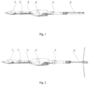
- the tandem-cumulative shot consists of a composite housing where the forearm 1 and the main cumulative warhead 2 are located, and an auxiliary jet engine 3 is set among them, by being connected to the primary cumulative warhead 2 by means of a bottom coupling element 4, preferably a bottom coupling bushing, and a drive unit, consisting of a primary jet engine 5 and a starter gunpowder charge 6 connected thereto with a stabilizer, which is connected to the rear part of the primary cumulative warhead.
- the cumulative forearm 1 includes a small-scale low-frequency cumulative unit to the auxiliary jet engine 3 is mounted to; at the rear end of it the bottom coupling bushing 4 is located, and the main warhead 2 is fixed to it.
- the bottom bushing 4 has an external form allowing it to absorb the energy of the detonated products of the cumulative forearm 1 and of the active elements of the armor, while simultaneously launching the blasting device 26 of the primary cumulative warhead 2.
- the cumulative forearm 1 is filled with a caliber up to 60 mm and consists of a blasting device 7 located in its front part, for example a piezo-generator connected to a current-conducting element 9 hosted in a fairing 8; we advise the conductor element 9 and the fairing 8 to be of conical shape.
- the fairing 8 is rigidly coupled to a conical-cylindrical housing; there is a cumulative unit with a cumulative funnel lining 10 with a conductor in its chamber.
- the lining is filled with a variable wall thickness progressively increasing from the top to the base in the range of 0.8 to 1.3 mm, and a diameter of not more than 48 mm and a height of not more than 39 mm.
- an explosive 12 In the chamber of the cumulative unit, there are an explosive 12 and a bottom blasting device 13 with a detonator located. It is preferable to use explosive 12 with parameters: a mass of 0.160 to 0.168kg; density of 1.76 to 1.8g/cm 3 ; a detonation speed rate equal to or greater than 8,000 m/s.
- the screen 11 of the forearm 1 Between the cumulative lining 10 and the detonator of the bottom blasting device 13, there is the screen 11 of the forearm 1; it is suitable to be made in a conical-spherical shape, and have the provision of a central hole passing through it - so the conductor can pass from the cumulative lining 10 and it is connected to the switch of the bottom blasting device 13.
- the screen 11 is compressed into the explosive substance 12 of the said cumulative unit.
- the screen 11 should be made of an inert material and its purpose is to deform the front of the detonation wave formed upon the launch of the explosive substance 12 in such a way that the formed front shall approach and progress along the profile of the outer forming of the cumulative funnel 10, dynamically deforming it, and thus facilitating and assisting in the formation of a low-grade cumulative jet flow of the cumulative unit.
- a characteristic feature of the forearm 1 is that the blasting device 7 of the forearm 1 is shaped under a spherical face surface, and it allows - after the submission of the detonation impulse from the bottom blasting device 13 to the explosive substance 12 - to form cumulative jet flow of a low gradient along its length.
- the formation of a low-grade cumulative jet flow provides the deactivation of the additionally mounted dynamic protective devices using different sources of energy, for example explosive substance, electrical power, energy generated by the reaction of active chemical substances, etc.
- a bilge block 14 mounted, and there is the auxiliary jet engine 3 mounted fast on it - and the engine 3 consists of a housing 15 of the auxiliary jet engine 3, where jet engine fuel 16 is stored.
- the pyro-delay-igniter 17 and the bottom 18 of the auxiliary jet engine 3 are located in the rear end of the jet engine 3 - this is, in its essence, a coupling element between the auxiliary jet engine 3 and the primary cumulative warhead 2.
- the bottom 18 is formed as a shaped element, for example a bushing, of cylindrical shape and a center hole threaded in it, and in a blasting device 19 of the primary warhead 2 is mounted in it.
- the bottom 18 is made in a way so that its middle and outer parts, especially in weakened section ( Fig.4 ), are filled with a small wall thickness.
- This constructive profile formation of the bottom 18 allows it to perform the function of a protective diaphragm, i.e. acting as a delay device, and its deformation in the said section allows the launch of the primary cumulative warhead 2 against the cumulative forearm 1 with a delay of 200-250 ⁇ s.
- the protective diaphragm is located at a distance from a cumulative funnel lining 23 with a conductor of the primary forehead 2, thus resulting in creating a space where the cumulative jet flow of the primary forehead 2 is formed, and it is not affected nor influenced by the products the forearm 1 or the active elements of the armor.
- the bulletproof-ness of the forearm 1 on homogeneous armored steel is not less than 300 mm.
- a conically shaped cavity is formed into the protective diaphragm and the coupling cone 20 of the primary warhead 2, where a conically shaped conductive element 21 is accommodated, the latter is used to transmit an electrical impulse generated by the piezoelectric blasting device 19 towards the cumulative funnel lining 23 with a conductor, or to the bottom blasting device 26 of the primary warhead 2, respectively.
- the primary cumulative warhead 2 consists of a cumulative unit and a front blasting device 19, preferably a piezo-generator, connected by means of a coupling cone 20 to a housing 22 of the primary warhead 2.
- the housing 22 accommodates: the conductive electrical element 21, the cumulative funnel lining 23 with a conductor, the explosive substance 24 of the primary warhead 2, and the screen 25 of the primary warhead 2 is housed behind the explosive.
- the coupling cone 20 is fast connected to the housing 22 preferably made in a cylindrical conical shape - and its inner chamber hosts the cumulative unit with a conical funnel lining 23 with an angle of opening of 60°, with a variable wall thickness progressively increasing from the top to the base from 0.8 to 2.2 mm, and the height being less than or equal to 78 mm, and the diameter of the cylindrical part - less than or equal to 94.5 mm, and the height of the cylindrical part - of up to 4.5 mm.
- the mass of explosive substance 20 shall be from 0.650 to 0.680 kg, and of density of not less than 1,8 g/cm 3 , with a detonation velocity of more than 8000 m/s.
- the bottom blasting device 26 of the primary warhead 2 is located at the rear part of the housing 22, the bottom blasting device 26 of the primary warhead 2 is located.
- the cumulative unit elements described here have been designed and constructed in a manner allowing - after the launch of cumulative unit - to form a high-speed cumulative jet flow, which provides the destruction of the homogeneous armor of thickness of more than 700 mm behind the active elements of the armored vehicle.
- the primary warhead 2 should preferably have a caliber smaller than or equal to 105 mm and should consist of a protective diaphragm located in the front, and not shown in the figures.
- the primary jet engine 5 is constructed in a cylindrical-conical shape, it consists of a bilge block 14' and a conical-cylindrical housing 27 ( Fig.5 ), located behind the block; the housing stores the fuel of the jet engine and the pyro-delay-igniter 17', contacting the bottom 28 of the primary jet engine 5.
- the bottom 28 - in its front part - has a flat vertically oriented surface and is arranged in a way as to close the combustion chamber of the primary jet engine 5, and at the same time it contains the combustion unit of the engine 5 consisting of an L-shaped hole in the bottom 28 having a strewing of black gunpowder smoke/smog 29 and a cartridge igniter 31.
- the geometric parameters and the configuration of the screening element 25 are in accordance with its functional purpose and in combination with the configuration of the cumulative lining 23, the housing 22, the type of the explosive substance 24, its energy parameters and their mutual location, deform and manage the front of the detonation wave generated by the detonation of the explosive substance 24.
- the blasting device 26 of the primary warhead 2 should be preferably constructed as piezoelectric and it is designed - while deforming the bottom bushing 6 of the auxiliary jet engine 3 in the weakened section, to generate an electrical impulse.
- the front part of the blasting device 19 should be made with a flat front and have it located at a predetermined distance from the convex inner cylindrical part of the bottom bushing 28, for example at a distance of 3-5 mm, having its convex inner cylindrical part pressing the front of the blasting device 19, while the electrical impulse generated by it is transmitted along the electrical circuit of the bottom part of the blasting device 26.
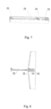
- the start gunpowder engine 6 consists of a stem 32 preferably made as a cylindrical body with a lot of radially oriented openings, while a powder bag, for example, black smoke gunpowder 29 is located in the inner surface of the stem 32 along its length, designed to ignite the primary charge, e.g. a tape-type nitroglycerine gunpowder, arranged around the nibs 35 of the stabilizer 5.
- a support member mounted not shown in the figures - and four nibs 33 are attached to it by means of hinges.
- the nibs 33 open from their collapsed position to 90 0 in the vertical position - under the centrifugal forces and countercurrent airflow.
- a turbine 34 is mounted, made in a cylindrical spiral shape, and a tracer 35 is mounted in the rear and inner part - to control the trajectory of the shot.
- the combustion of the black smoke gunpowder and the tapes of nitroglycerine gunpowder in the gunpowder start charge 6 provides a reactive force that propels and triggers the shot forward with an initial velocity of at least 70 m/s.
- Typical for the turbine 34 is its constructional design, particularly with respect to the length and the area of the ribs, formed by a helical line and designed so that when the tandem shot takes off of the grenade, the necessary angular velocity of 7.8 rotations/sec is ensured, achieved by the discharge of the gunpowder gases through the cross section of the turbine 34, these gases swirl around the helical line of the ribs, thereby creating a rotational movement of the shot in the grenade.
- the angular velocity of the shot is needed, on the one hand, to create a centrifugal force that allows the four stabilizer nibs 33 to be opened after the shot has been fired from the grenade launcher at a certain distance, which in turn is necessary to create a lifting force, against the drop of the shot at the initial stage of the flight path trajectory, in particular by the time of the inclusion of the auxiliary 3 and the primary 5 jet engines.
- maintaining the said angular velocity is necessary in order to stabilize the shot flight, along its trajectory until it meets the barrier.
- the auxiliary jet engine 3, located between the forearm 1 and the primary cumulative warhead 2 will have a reduced overall size, approximately half that of the primary jet engine 5, and it shall respectively reflect the energy properties and the action time of the reactive power and thrust each of the two engines 3 and 5 creates. This practically predetermines the performance of the two engines to be different whereas the combustion time of the auxiliary jet engine 3 is approximately 0.3 s, while the primary engine 5 has approx. 0.7 s.
- tandem-cumulative shot there is a provision for the use of the same primary 5 and auxiliary 3 jet engines as construction and technical parameters, which may differ only in the length of the casing and the fuel 30, made as a cylindrical nitroglycerine cartridge, especially along the cylindrical cartridge and along the construction of the bottom bushing 4 of the auxiliary jet engine 3, which has several functional uses, such as: acting as a closing element of the chamber of the auxiliary jet engine 3, as well as to join the auxiliary jet engine 3 and the primary cumulative warhead 2.
- the angular velocity of the shot along its trajectory is maintained thanks to the profile of the four nibs 33, made with one-sided tangential gradient, resulting - due to the air countercurrent - in a swirling motion and maintaining the angular velocity along the trajectory.
- the stabilizer constructed so that the maximum width of the nibs 33 in the open position is 437-450 mm, and the total length of the stabilizer is from 290 to 292.5 mm, while the nibs 33 are constructively ensured to have a maximum contact area.
- tandem-cumulative shot described herein with two jet engines 3 and 5 and a gunpowder starting charge 6 with a stabilizer can be presented as follows: after placing the tandem-cumulative shot in the grenade launcher and producing a shot, as a result of the gases formed by the gunpowder starting charge 6, a reactive force is formed and it propels the tandem-cumulative shot forward. Upon discharge of the so formed gunpowder gases through the helical section of the turbine 34, the shot is transmitted to a rotary motion with an angular velocity of 7..8 rotations per second and an initial take-off speed from the grenade mouth not less than 70 m/s.
- the four nibs 33 of the stabilizer 6 are opened under the operation of the centrifugal forces and countercurrent airflow. Approximately up to 12 meters from the start of the shot trajectory, the operation of the inertial and pyrotechnic safety mechanisms of the bottom blasting devices of the forearm and the primary warhead are completed, resulting in the tandem-cumulative shot being ready to encounter the target.
- the pyro-delay-ignition devices 17, 17' of the two jet engines 3 and 5 are triggered, and then - under the operation of the reactive forces, the shot accelerates and maintains a march velocity for the shot to reach the target and have the latter damaged by the tandem warhead.
- the operation of the two jet engines 3 and 5 is parallel, with the auxiliary jet engine 3 running approximately 0.3 ... 0.34 s, while the second one runs 0.7... 074 s in the temperature range of -50 0 C to + 50 0 C; by observing these parameters this ensures a straight shot can be made at a distance of not less than 300 m.
- the piezo-generator 7 of the forearm 1 When the tandem-cumulative shot encounters with a barrier, the piezo-generator 7 of the forearm 1 generates an electrical impulse transmitted - along the electric circuit - to the spark electro-detonator (not shown in the figures) of the bottom blasting device 13 further delivering a detonating impulse to the explosive substance 12 of the cumulative charge.
- the spherical front of the detonation wave thus formed spreads over the bursting charge by passing through the cone-spherical form of the screen 11, thereby altering its shape and parameters.
- the formed new detonation wave front fits closely to the cumulative lining 10 profile, dynamically deforming it and forming a cumulative jet flow of a low gradient of the velocity along its length.
- the formed low-grade cumulative jet flow interacts with the active elements of the armor, by triggering and deactivating them. Parallel to it, the energy released by the detonation products of the forearm 1, the active elements of the armor and the mechanical shock wave impact the cross section of the bilge block 14 of the auxiliary jet engine 3, thus deforming the bottom sleeve 4 in the n/n section.
- the formed spherical front of the detonation wave spreads along the bursting charge, bypassing the cone-spherical form of the screen 25, thereby altering its shape and parameters.
- the newly formed detonation wave front fits closely to the profile of the cumulative lining 23, dynamically deforming it and forming a high-speed cumulative jet flow that interacts with the target - the main armor of the armored vehicle.
- Forming of high-speed cumulative jet flow ensures the striking of the homogeneous armor with a thickness of not less than 700 mm, located behind the active elements of the armored vehicle.
- the delaying action of the primary warhead 2 in relation to the forearm 1 is determined by the sum of the times for the launching of the blasting device 13 of the forearm 1, the formation of the cumulative jet flow and its interaction with the dynamic elements of the armor, the dynamic deformation of the bottom bushing 4 of the auxiliary jet engine, the launch of the primary warhead 2, the formation of a high-speed cumulative jet flow, and its interaction with the main armor of the armored vehicle, the total sum of the time being in the range of 250-300 ⁇ s.
Landscapes
- Engineering & Computer Science (AREA)
- Chemical & Material Sciences (AREA)
- Combustion & Propulsion (AREA)
- General Engineering & Computer Science (AREA)
- Drilling And Exploitation, And Mining Machines And Methods (AREA)
- Aiming, Guidance, Guns With A Light Source, Armor, Camouflage, And Targets (AREA)
- Paper (AREA)
- Feeding, Discharge, Calcimining, Fusing, And Gas-Generation Devices (AREA)
Claims (13)
- Tandem-kumulativer Schuss mit einem zusammengesetzten Körper, der in seinem vorderen Teil einen vorstehenden Gefechtsteil (1) und einen Hauptgefechtsteils (2) aufnimmt, wobei der vorstehende Gefechtsteil (1) einen kumulativen Gefechtskopf und ein Hilfsstrahltriebwerk (3) zwischen dem kumulativen Gefechtskopf und dem Hauptgefechtsteil aufweist, wobei das Hilfsstrahltriebwerk (3) mit dem Hauptgefechtskopf (2) mittels einer Bodenhülse (4) verbunden ist, wobei der kumulative Gefechtskopf und der Hauptgefechtsteil (2) mit identischen piezoelektrischen vorderen (7, 19) und unteren (13, 26) Sprengvorrichtungen ausgestattet sind, wobei am hinteren Ende des Hauptgefechtsteils (2) eine Antriebseinheit, bestehend aus einem Hauptstrahltriebwerk (5) und einer Schießpulver- Zündladung (6) mit einem Stabilisator, angebracht ist, wobei, innerhalb des Hauptgefechtsteils (2) die piezoelektrische vordere Sprengvorrichtung (19) des Hauptgefechtsteils (2) angeordnet ist, die über eine elektrische Verbindung mit der piezoelektrischen unteren Sprengvorrichtung (26) des Hauptgefechtsteils (2) verbunden ist, wobei die piezoelektrische vordere Sprengvorrichtung (7) des vorstehenden Gefechtsteils (1) mittels einer elektrischen Verbindung mit der piezoelektrischen unteren Sprengvorrichtung (13) des vorstehenden Gefechtsteils (1) verbunden ist und wobei die piezoelektrische vordere Sprengvorrichtung (7) des vorstehenden Gefechtsteils (1) mit der piezoelektrischen unteren Sprengvorrichtung (13) des vorstehenden Gefechtsteils (1) mittels einer elektrischen Verbindung verbunden ist und wobei die piezoelektrische vordere Sprengvorrichtung (7) des vorstehenden Gefechtskopfes im vorstehenden Gefechtsteil (1) angebracht ist, wobei die vordere Sprengvorrichtung (7) des vorstehenden Gefechtteils (1) unter einer kugelförmigen Stirnfläche geformt ist, wobei die Schießpulver-Zündladung (6) mit einem Stabilisator versehen ist, der einen Schaft (32) aufweist, in dessen Innerem flache, tangential abgeschrägte Spitzen (33) mit Hilfe von Scharnieren angebracht sind, wobei hinter dem Stabilisator eine Turbine (34) mit schraubenlinienförmig ausgebildeten Rippen angebracht ist.
- Tandem-Kumulativschuss nach Anspruch 1, dadurch gekennzeichnet, dass der vorstehende Gefechtsteil (1) und der Hauptgefechtsteil (2) koaxial angeordnet sind.
- Tandem-kumulativer Schuss nach Anspruch 1, dadurch gekennzeichnet, dass die Bodenhülse (4) mit einer zylindrischen Körperform ausgebildet ist, mit variabler Form und Wandstärke, wobei der mittlere und äußere Teil mit einer minimalen Dicke im geschwächten Abschnitt bewerkstelligt wird.
- Tandem-kumulativer Schuss nach Anspruch 1, dadurch gekennzeichnet, dass die Bodenhülse (4) an einem Ende in einer massiven (dicken) Wand endet, und die Wand zu ihrer Innenseite hin konvex ist, in Form eines Zylinders, und sich in einem Abstand von 3 bis 5 mm von der piezoelektrischen Sprengvorrichtung (19) des Hauptgefechtsteils (2) befindet.
- Tandem-kumulativer Schuss nach Anspruch 1, dadurch gekennzeichnet, dass die Verbindung zwischen dem vorstehenden Gefechtsteil (1) und dem Hilfsstrahltriebwerk (3) starr und die Verbindung zwischen der Bodenhülse (4) und dem kumulativen Hauptgefechtsteil (2) verformbar ist.
- Tandem-kumulativer Schuss nach Anspruch 1, dadurch gekennzeichnet, dass die Verbindung zwischen dem kumulativen Hauptgefechtsteil (2), dem Hauptstrahltriebwerk (5) und der Schießpulver-Zündladung (6) starr ist.
- Tandem-kumulativer Schuss nach Anspruch 1, dadurch gekennzeichnet, dass der vorstehende Gefechtsteil (1) mit einem Kaliber von höchstens 60 mm einen Piezogenerator (7) aufweist, der mit einem stromleitenden Element (9) verbunden ist, das in einer Verkleidung (8) mit konischer Form untergebracht ist, wobei die Verkleidung (8) fest mit einem konisch-zylindrischen Gehäuse verbunden ist, in dessen Hohlraum eine kumulative Einheit untergebracht ist.
- Tandem-kumulativer Schuss nach Anspruch 1, dadurch gekennzeichnet, dass die kumulative Auskleidung (10) eine variable Wandstärke aufweist, die von der Spitze zum Boden hin progressiv zunimmt.
- Tandem-kumulativer Schuss nach Anspruch 1, dadurch gekennzeichnet, dass der Schirm (11) eine konisch-sphärische Form hat, mit einer zentralen Öffnung, durch die ein Leiter der kumulativen Auskleidung (10) verläuft, der mit einem Anschluss der Bodensprengvorrichtung (13) verbunden ist.
- Tandem-kumulativer Schuss nach Anspruch 1, dadurch gekennzeichnet, dass der Schirm (11) aus einem inerten Material bewerkstelligt wird und in den Sprengstoff (12) der kumulativen Einheit eingepresst ist.
- Tandem-kumulativer Schuss nach Anspruch 1, dadurch gekennzeichnet, dass der Hauptgefechtsteil (2) ein Kaliber von 105 mm oder weniger hat und aus einem Diaphragma mit einer zentral geformten Bohrung besteht, an der die piezoelektrische Sprengvorrichtung (19) angebracht ist, die durch ein stromleitendes Element (21) verbunden ist, das im Innenraum eines Kupplungskonus (20) mit einem Gehäuse (22) von zylindrisch-konischer Form untergebracht ist, in dessen innerem Hohlraum eine kumulative Einheit angebracht ist, die eine zylindrisch-konische Auskleidung (23) aufweist mit einem Öffnungswinkel von 60° und einer variablen Wandstärke, die von der Spitze zur Basis hin progressiv zunimmt.
- Tandem-kumulativer Schuss nach Anspruch 1, dadurch gekennzeichnet, dass das Abschirmelement (25) in den Sprengstoff (24) eingepresst und zwischen der kumulativen Auskleidung (23) und der Bodensprengvorrichtung (26) angeordnet ist, bewerkstelligt mit einer konisch-sphärischen Form und einer zentral geformten Öffnung, durch die der Leiter der kumulativen Auskleidung (23) hindurchgeht, verbunden mit einem Anschluss der unteren Sprengvorrichtung (26).
- Tandem-kumulativer Schuss nach Anspruch 1, dadurch gekennzeichnet, dass das Hilfsstrahltriebwerk (3) und das Hauptstrahltriebwerk (4) unterschiedliche Körperlängen (15) und (22) aufweisen und mit identischen Düsenblöcken (14,14') und Pyro(zeit)zündern (17, 17') versehen sind.
Priority Applications (2)
| Application Number | Priority Date | Filing Date | Title |
|---|---|---|---|
| RS20240497A RS65463B1 (sr) | 2017-11-08 | 2018-01-31 | Tandem-kumulativni projektil |
| SI201831092T SI3714229T1 (sl) | 2017-11-08 | 2018-01-31 | Tandemski kumulativni izstrelek |
Applications Claiming Priority (2)
| Application Number | Priority Date | Filing Date | Title |
|---|---|---|---|
| BG390317 | 2017-11-08 | ||
| PCT/BG2018/000008 WO2019090399A1 (en) | 2017-11-08 | 2018-01-31 | Tandem-cumulative shot |
Publications (2)
| Publication Number | Publication Date |
|---|---|
| EP3714229A1 EP3714229A1 (de) | 2020-09-30 |
| EP3714229B1 true EP3714229B1 (de) | 2024-02-28 |
Family
ID=61244324
Family Applications (1)
| Application Number | Title | Priority Date | Filing Date |
|---|---|---|---|
| EP18705814.4A Active EP3714229B1 (de) | 2017-11-08 | 2018-01-31 | Tandemgeschoss |
Country Status (5)
| Country | Link |
|---|---|
| EP (1) | EP3714229B1 (de) |
| EA (1) | EA038130B1 (de) |
| RS (1) | RS65463B1 (de) |
| SI (1) | SI3714229T1 (de) |
| WO (1) | WO2019090399A1 (de) |
Families Citing this family (1)
| Publication number | Priority date | Publication date | Assignee | Title |
|---|---|---|---|---|
| IL285253B2 (en) | 2021-07-27 | 2023-08-01 | Rafael Advanced Defense Systems Ltd | Ammunition breaks through barriers |
Family Cites Families (9)
| Publication number | Priority date | Publication date | Assignee | Title |
|---|---|---|---|---|
| US2894457A (en) | 1955-03-18 | 1959-07-14 | Magnavox Co | Detonation delay device |
| NL129818C (de) | 1959-11-02 | 1900-01-01 | Energa | |
| DE3712697A1 (de) * | 1987-04-14 | 1990-07-05 | Diehl Gmbh & Co | Geschoss mit raketenzusatzantrieb |
| DE3942841A1 (de) | 1989-12-23 | 1991-06-27 | Dynamit Nobel Ag | Einstellbarer abstandshalter auf einem hohlladungsgefechtskopf, umschaltbar fuer tiefen- oder seitenwirkung |
| USH867H (en) * | 1990-07-23 | 1991-01-01 | The United States Of America As Represented By The Secretary Of The Army | Tandem warheads separated by missile booster motor |
| DE4240084A1 (de) | 1992-11-28 | 1994-06-01 | Dynamit Nobel Ag | Tandemgefechtskopf mit piezoelektrischen Aufschlagzündern |
| SE507558C2 (sv) * | 1995-01-23 | 1998-06-22 | Bofors Ab | Granat med multiladdningar |
| DE19827171A1 (de) * | 1998-06-18 | 1999-12-23 | Dynamit Nobel Ag | Waffe, insbesondere Panzerabwehrwaffe |
| BG63851B1 (bg) * | 1999-11-01 | 2003-03-31 | "Вмз" Еад | Тандемно-кумулативна бойна част |
-
2018
- 2018-01-31 SI SI201831092T patent/SI3714229T1/sl unknown
- 2018-01-31 EA EA202091152A patent/EA038130B1/ru unknown
- 2018-01-31 EP EP18705814.4A patent/EP3714229B1/de active Active
- 2018-01-31 WO PCT/BG2018/000008 patent/WO2019090399A1/en not_active Ceased
- 2018-01-31 RS RS20240497A patent/RS65463B1/sr unknown
Also Published As
| Publication number | Publication date |
|---|---|
| EP3714229A1 (de) | 2020-09-30 |
| EA038130B1 (ru) | 2021-07-09 |
| SI3714229T1 (sl) | 2024-06-28 |
| RS65463B1 (sr) | 2024-05-31 |
| EA202091152A1 (ru) | 2020-09-17 |
| WO2019090399A1 (en) | 2019-05-16 |
Similar Documents
| Publication | Publication Date | Title |
|---|---|---|
| EP3172525B1 (de) | Gerichtete fragmentierungsmunition mit geringem kollateralschaden | |
| RU2291378C1 (ru) | Реактивный снаряд | |
| EP3714229B1 (de) | Tandemgeschoss | |
| RU2439473C1 (ru) | Управляемый реактивный снаряд | |
| US8297190B1 (en) | Door breaching device with radially expandable explosive | |
| RU2722193C1 (ru) | Отделяющаяся осколочно-фугасная головная часть снаряда | |
| US5016537A (en) | Controlled explosive, hypervelocity self-contained round for a large caliber gun | |
| US12332032B2 (en) | Barrier-breaching munition | |
| KR101098114B1 (ko) | 이중 탄두형 폭발탄 | |
| EP3577413B1 (de) | Kumulativer aerosolsprengkopf | |
| GB191305338A (en) | Improvements in Projectiles. | |
| CN105674810B (zh) | 一种二次杀伤箭装置 | |
| BG67226B1 (bg) | Кумулативно-термобаричен изстрел | |
| BG2889U1 (bg) | Тандемно-кумулативен изстрел | |
| RU2510484C1 (ru) | Граната "болотея" к ручному гранатомету, содержащая кассетную боевую часть с осколочными субснарядами | |
| RU207654U1 (ru) | Осколочно-фугасный снаряд | |
| RU2738687C2 (ru) | Бронебойный оперенный подкалиберный снаряд | |
| RU2363919C1 (ru) | Осколочно-пучковый снаряд "торопец" | |
| US1290275A (en) | Projectile. | |
| RU2247931C1 (ru) | Кассетный боеприпас "аспид" с осколочными боевыми элементами двойного действия | |
| JP2000337800A (ja) | 弾子および弾頭 | |
| RU2646874C1 (ru) | Активный снаряд | |
| WO2017136905A1 (en) | A fragmentation shot with ready destructive elements | |
| RU90190U1 (ru) | Ракета для воздействия на облака | |
| EA041029B1 (ru) | Кумулятивный термобарический выстрел |
Legal Events
| Date | Code | Title | Description |
|---|---|---|---|
| STAA | Information on the status of an ep patent application or granted ep patent |
Free format text: STATUS: UNKNOWN |
|
| STAA | Information on the status of an ep patent application or granted ep patent |
Free format text: STATUS: THE INTERNATIONAL PUBLICATION HAS BEEN MADE |
|
| PUAI | Public reference made under article 153(3) epc to a published international application that has entered the european phase |
Free format text: ORIGINAL CODE: 0009012 |
|
| STAA | Information on the status of an ep patent application or granted ep patent |
Free format text: STATUS: REQUEST FOR EXAMINATION WAS MADE |
|
| 17P | Request for examination filed |
Effective date: 20200819 |
|
| AK | Designated contracting states |
Kind code of ref document: A1 Designated state(s): AL AT BE BG CH CY CZ DE DK EE ES FI FR GB GR HR HU IE IS IT LI LT LU LV MC MK MT NL NO PL PT RO RS SE SI SK SM TR |
|
| AX | Request for extension of the european patent |
Extension state: BA ME |
|
| DAV | Request for validation of the european patent (deleted) | ||
| STAA | Information on the status of an ep patent application or granted ep patent |
Free format text: STATUS: EXAMINATION IS IN PROGRESS |
|
| 17Q | First examination report despatched |
Effective date: 20230224 |
|
| GRAP | Despatch of communication of intention to grant a patent |
Free format text: ORIGINAL CODE: EPIDOSNIGR1 |
|
| STAA | Information on the status of an ep patent application or granted ep patent |
Free format text: STATUS: GRANT OF PATENT IS INTENDED |
|
| INTG | Intention to grant announced |
Effective date: 20230929 |
|
| GRAS | Grant fee paid |
Free format text: ORIGINAL CODE: EPIDOSNIGR3 |
|
| GRAA | (expected) grant |
Free format text: ORIGINAL CODE: 0009210 |
|
| STAA | Information on the status of an ep patent application or granted ep patent |
Free format text: STATUS: THE PATENT HAS BEEN GRANTED |
|
| AK | Designated contracting states |
Kind code of ref document: B1 Designated state(s): AL AT BE BG CH CY CZ DE DK EE ES FI FR GB GR HR HU IE IS IT LI LT LU LV MC MK MT NL NO PL PT RO RS SE SI SK SM TR |
|
| REG | Reference to a national code |
Ref country code: GB Ref legal event code: FG4D |
|
| REG | Reference to a national code |
Ref country code: CH Ref legal event code: EP |
|
| REG | Reference to a national code |
Ref country code: DE Ref legal event code: R096 Ref document number: 602018065814 Country of ref document: DE |
|
| REG | Reference to a national code |
Ref country code: IE Ref legal event code: FG4D |
|
| REG | Reference to a national code |
Ref country code: LT Ref legal event code: MG9D |
|
| PG25 | Lapsed in a contracting state [announced via postgrant information from national office to epo] |
Ref country code: IS Free format text: LAPSE BECAUSE OF FAILURE TO SUBMIT A TRANSLATION OF THE DESCRIPTION OR TO PAY THE FEE WITHIN THE PRESCRIBED TIME-LIMIT Effective date: 20240628 |
|
| REG | Reference to a national code |
Ref country code: NL Ref legal event code: MP Effective date: 20240228 |
|
| PG25 | Lapsed in a contracting state [announced via postgrant information from national office to epo] |
Ref country code: LT Free format text: LAPSE BECAUSE OF FAILURE TO SUBMIT A TRANSLATION OF THE DESCRIPTION OR TO PAY THE FEE WITHIN THE PRESCRIBED TIME-LIMIT Effective date: 20240228 |
|
| PG25 | Lapsed in a contracting state [announced via postgrant information from national office to epo] |
Ref country code: GR Free format text: LAPSE BECAUSE OF FAILURE TO SUBMIT A TRANSLATION OF THE DESCRIPTION OR TO PAY THE FEE WITHIN THE PRESCRIBED TIME-LIMIT Effective date: 20240529 |
|
| PG25 | Lapsed in a contracting state [announced via postgrant information from national office to epo] |
Ref country code: HR Free format text: LAPSE BECAUSE OF FAILURE TO SUBMIT A TRANSLATION OF THE DESCRIPTION OR TO PAY THE FEE WITHIN THE PRESCRIBED TIME-LIMIT Effective date: 20240228 Ref country code: NL Free format text: LAPSE BECAUSE OF FAILURE TO SUBMIT A TRANSLATION OF THE DESCRIPTION OR TO PAY THE FEE WITHIN THE PRESCRIBED TIME-LIMIT Effective date: 20240228 |
|
| PG25 | Lapsed in a contracting state [announced via postgrant information from national office to epo] |
Ref country code: ES Free format text: LAPSE BECAUSE OF FAILURE TO SUBMIT A TRANSLATION OF THE DESCRIPTION OR TO PAY THE FEE WITHIN THE PRESCRIBED TIME-LIMIT Effective date: 20240228 |
|
| PG25 | Lapsed in a contracting state [announced via postgrant information from national office to epo] |
Ref country code: NO Free format text: LAPSE BECAUSE OF FAILURE TO SUBMIT A TRANSLATION OF THE DESCRIPTION OR TO PAY THE FEE WITHIN THE PRESCRIBED TIME-LIMIT Effective date: 20240528 Ref country code: NL Free format text: LAPSE BECAUSE OF FAILURE TO SUBMIT A TRANSLATION OF THE DESCRIPTION OR TO PAY THE FEE WITHIN THE PRESCRIBED TIME-LIMIT Effective date: 20240228 Ref country code: LT Free format text: LAPSE BECAUSE OF FAILURE TO SUBMIT A TRANSLATION OF THE DESCRIPTION OR TO PAY THE FEE WITHIN THE PRESCRIBED TIME-LIMIT Effective date: 20240228 Ref country code: IS Free format text: LAPSE BECAUSE OF FAILURE TO SUBMIT A TRANSLATION OF THE DESCRIPTION OR TO PAY THE FEE WITHIN THE PRESCRIBED TIME-LIMIT Effective date: 20240628 Ref country code: HR Free format text: LAPSE BECAUSE OF FAILURE TO SUBMIT A TRANSLATION OF THE DESCRIPTION OR TO PAY THE FEE WITHIN THE PRESCRIBED TIME-LIMIT Effective date: 20240228 Ref country code: GR Free format text: LAPSE BECAUSE OF FAILURE TO SUBMIT A TRANSLATION OF THE DESCRIPTION OR TO PAY THE FEE WITHIN THE PRESCRIBED TIME-LIMIT Effective date: 20240529 Ref country code: FI Free format text: LAPSE BECAUSE OF FAILURE TO SUBMIT A TRANSLATION OF THE DESCRIPTION OR TO PAY THE FEE WITHIN THE PRESCRIBED TIME-LIMIT Effective date: 20240228 Ref country code: ES Free format text: LAPSE BECAUSE OF FAILURE TO SUBMIT A TRANSLATION OF THE DESCRIPTION OR TO PAY THE FEE WITHIN THE PRESCRIBED TIME-LIMIT Effective date: 20240228 |
|
| PG25 | Lapsed in a contracting state [announced via postgrant information from national office to epo] |
Ref country code: PT Free format text: LAPSE BECAUSE OF FAILURE TO SUBMIT A TRANSLATION OF THE DESCRIPTION OR TO PAY THE FEE WITHIN THE PRESCRIBED TIME-LIMIT Effective date: 20240628 |
|
| PG25 | Lapsed in a contracting state [announced via postgrant information from national office to epo] |
Ref country code: SE Free format text: LAPSE BECAUSE OF FAILURE TO SUBMIT A TRANSLATION OF THE DESCRIPTION OR TO PAY THE FEE WITHIN THE PRESCRIBED TIME-LIMIT Effective date: 20240228 Ref country code: PT Free format text: LAPSE BECAUSE OF FAILURE TO SUBMIT A TRANSLATION OF THE DESCRIPTION OR TO PAY THE FEE WITHIN THE PRESCRIBED TIME-LIMIT Effective date: 20240628 Ref country code: LV Free format text: LAPSE BECAUSE OF FAILURE TO SUBMIT A TRANSLATION OF THE DESCRIPTION OR TO PAY THE FEE WITHIN THE PRESCRIBED TIME-LIMIT Effective date: 20240228 |
|
| REG | Reference to a national code |
Ref country code: AT Ref legal event code: UEP Ref document number: 1661613 Country of ref document: AT Kind code of ref document: T Effective date: 20240228 |
|
| PG25 | Lapsed in a contracting state [announced via postgrant information from national office to epo] |
Ref country code: DK Free format text: LAPSE BECAUSE OF FAILURE TO SUBMIT A TRANSLATION OF THE DESCRIPTION OR TO PAY THE FEE WITHIN THE PRESCRIBED TIME-LIMIT Effective date: 20240228 |
|
| PG25 | Lapsed in a contracting state [announced via postgrant information from national office to epo] |
Ref country code: SM Free format text: LAPSE BECAUSE OF FAILURE TO SUBMIT A TRANSLATION OF THE DESCRIPTION OR TO PAY THE FEE WITHIN THE PRESCRIBED TIME-LIMIT Effective date: 20240228 |
|
| PG25 | Lapsed in a contracting state [announced via postgrant information from national office to epo] |
Ref country code: EE Free format text: LAPSE BECAUSE OF FAILURE TO SUBMIT A TRANSLATION OF THE DESCRIPTION OR TO PAY THE FEE WITHIN THE PRESCRIBED TIME-LIMIT Effective date: 20240228 |
|
| PG25 | Lapsed in a contracting state [announced via postgrant information from national office to epo] |
Ref country code: SM Free format text: LAPSE BECAUSE OF FAILURE TO SUBMIT A TRANSLATION OF THE DESCRIPTION OR TO PAY THE FEE WITHIN THE PRESCRIBED TIME-LIMIT Effective date: 20240228 Ref country code: EE Free format text: LAPSE BECAUSE OF FAILURE TO SUBMIT A TRANSLATION OF THE DESCRIPTION OR TO PAY THE FEE WITHIN THE PRESCRIBED TIME-LIMIT Effective date: 20240228 Ref country code: DK Free format text: LAPSE BECAUSE OF FAILURE TO SUBMIT A TRANSLATION OF THE DESCRIPTION OR TO PAY THE FEE WITHIN THE PRESCRIBED TIME-LIMIT Effective date: 20240228 |
|
| REG | Reference to a national code |
Ref country code: DE Ref legal event code: R097 Ref document number: 602018065814 Country of ref document: DE |
|
| PLBE | No opposition filed within time limit |
Free format text: ORIGINAL CODE: 0009261 |
|
| STAA | Information on the status of an ep patent application or granted ep patent |
Free format text: STATUS: NO OPPOSITION FILED WITHIN TIME LIMIT |
|
| 26N | No opposition filed |
Effective date: 20241129 |
|
| PGFP | Annual fee paid to national office [announced via postgrant information from national office to epo] |
Ref country code: DE Payment date: 20250129 Year of fee payment: 8 |
|
| PGFP | Annual fee paid to national office [announced via postgrant information from national office to epo] |
Ref country code: RO Payment date: 20250120 Year of fee payment: 8 |
|
| PGFP | Annual fee paid to national office [announced via postgrant information from national office to epo] |
Ref country code: BG Payment date: 20250114 Year of fee payment: 8 |
|
| PGFP | Annual fee paid to national office [announced via postgrant information from national office to epo] |
Ref country code: BE Payment date: 20250127 Year of fee payment: 8 Ref country code: AT Payment date: 20250120 Year of fee payment: 8 Ref country code: CH Payment date: 20250201 Year of fee payment: 8 Ref country code: SI Payment date: 20250114 Year of fee payment: 8 |
|
| PGFP | Annual fee paid to national office [announced via postgrant information from national office to epo] |
Ref country code: PL Payment date: 20250129 Year of fee payment: 8 Ref country code: FR Payment date: 20250127 Year of fee payment: 8 Ref country code: CZ Payment date: 20250116 Year of fee payment: 8 |
|
| PGFP | Annual fee paid to national office [announced via postgrant information from national office to epo] |
Ref country code: IT Payment date: 20250122 Year of fee payment: 8 Ref country code: GB Payment date: 20250121 Year of fee payment: 8 Ref country code: SK Payment date: 20250120 Year of fee payment: 8 |
|
| PGFP | Annual fee paid to national office [announced via postgrant information from national office to epo] |
Ref country code: RS Payment date: 20250117 Year of fee payment: 8 |
|
| PGFP | Annual fee paid to national office [announced via postgrant information from national office to epo] |
Ref country code: TR Payment date: 20250117 Year of fee payment: 8 |
|
| PGFP | Annual fee paid to national office [announced via postgrant information from national office to epo] |
Ref country code: AL Payment date: 20250117 Year of fee payment: 8 |
|
| PG25 | Lapsed in a contracting state [announced via postgrant information from national office to epo] |
Ref country code: MC Free format text: LAPSE BECAUSE OF FAILURE TO SUBMIT A TRANSLATION OF THE DESCRIPTION OR TO PAY THE FEE WITHIN THE PRESCRIBED TIME-LIMIT Effective date: 20240228 |
|
| PG25 | Lapsed in a contracting state [announced via postgrant information from national office to epo] |
Ref country code: IE Free format text: LAPSE BECAUSE OF NON-PAYMENT OF DUE FEES Effective date: 20250131 |
|
| REG | Reference to a national code |
Ref country code: CH Ref legal event code: U11 Free format text: ST27 STATUS EVENT CODE: U-0-0-U10-U11 (AS PROVIDED BY THE NATIONAL OFFICE) Effective date: 20260201 |
|
| PGFP | Annual fee paid to national office [announced via postgrant information from national office to epo] |
Ref country code: LU Payment date: 20260129 Year of fee payment: 9 |