EP3714229B1 - Tandem-cumulative shot - Google Patents
Tandem-cumulative shot Download PDFInfo
- Publication number
- EP3714229B1 EP3714229B1 EP18705814.4A EP18705814A EP3714229B1 EP 3714229 B1 EP3714229 B1 EP 3714229B1 EP 18705814 A EP18705814 A EP 18705814A EP 3714229 B1 EP3714229 B1 EP 3714229B1
- Authority
- EP
- European Patent Office
- Prior art keywords
- cumulative
- primary
- warhead
- tandem
- forearm
- Prior art date
- Legal status (The legal status is an assumption and is not a legal conclusion. Google has not performed a legal analysis and makes no representation as to the accuracy of the status listed.)
- Active
Links
- 230000001186 cumulative effect Effects 0.000 claims description 89
- 238000005422 blasting Methods 0.000 claims description 56
- 210000000245 forearm Anatomy 0.000 claims description 53
- 239000003721 gunpowder Substances 0.000 claims description 26
- 239000002360 explosive Substances 0.000 claims description 22
- 239000003381 stabilizer Substances 0.000 claims description 21
- 239000000126 substance Substances 0.000 claims description 18
- 239000004020 conductor Substances 0.000 claims description 14
- 230000008878 coupling Effects 0.000 claims description 13
- 238000010168 coupling process Methods 0.000 claims description 13
- 238000005859 coupling reaction Methods 0.000 claims description 13
- 239000002131 composite material Substances 0.000 claims description 6
- 239000000463 material Substances 0.000 claims description 3
- 230000000630 rising effect Effects 0.000 claims 1
- 238000005474 detonation Methods 0.000 description 17
- 230000001681 protective effect Effects 0.000 description 7
- 239000007858 starting material Substances 0.000 description 6
- SNIOPGDIGTZGOP-UHFFFAOYSA-N Nitroglycerin Chemical compound [O-][N+](=O)OCC(O[N+]([O-])=O)CO[N+]([O-])=O SNIOPGDIGTZGOP-UHFFFAOYSA-N 0.000 description 5
- 230000009471 action Effects 0.000 description 5
- 230000015572 biosynthetic process Effects 0.000 description 5
- 238000010276 construction Methods 0.000 description 5
- 239000000446 fuel Substances 0.000 description 5
- 229960003711 glyceryl trinitrate Drugs 0.000 description 5
- 238000002485 combustion reaction Methods 0.000 description 4
- 239000007789 gas Substances 0.000 description 4
- 230000007246 mechanism Effects 0.000 description 4
- 239000000779 smoke Substances 0.000 description 4
- 230000004888 barrier function Effects 0.000 description 3
- 230000000694 effects Effects 0.000 description 3
- 230000035939 shock Effects 0.000 description 3
- 239000000006 Nitroglycerin Substances 0.000 description 2
- 229910000710 Rolled homogeneous armour Inorganic materials 0.000 description 2
- 230000008901 benefit Effects 0.000 description 2
- 230000009172 bursting Effects 0.000 description 2
- 238000006243 chemical reaction Methods 0.000 description 2
- 230000006378 damage Effects 0.000 description 2
- 238000010304 firing Methods 0.000 description 2
- 210000001061 forehead Anatomy 0.000 description 2
- 230000003993 interaction Effects 0.000 description 2
- 239000000700 radioactive tracer Substances 0.000 description 2
- 230000001960 triggered effect Effects 0.000 description 2
- 229910000831 Steel Inorganic materials 0.000 description 1
- 230000009286 beneficial effect Effects 0.000 description 1
- 239000002775 capsule Substances 0.000 description 1
- 230000009849 deactivation Effects 0.000 description 1
- 230000001419 dependent effect Effects 0.000 description 1
- 210000003746 feather Anatomy 0.000 description 1
- 238000004519 manufacturing process Methods 0.000 description 1
- 239000000843 powder Substances 0.000 description 1
- 238000012216 screening Methods 0.000 description 1
- 230000006641 stabilisation Effects 0.000 description 1
- 238000011105 stabilization Methods 0.000 description 1
- 239000010959 steel Substances 0.000 description 1
Images


Classifications
-
- F—MECHANICAL ENGINEERING; LIGHTING; HEATING; WEAPONS; BLASTING
- F42—AMMUNITION; BLASTING
- F42B—EXPLOSIVE CHARGES, e.g. FOR BLASTING, FIREWORKS, AMMUNITION
- F42B12/00—Projectiles, missiles or mines characterised by the warhead, the intended effect, or the material
- F42B12/02—Projectiles, missiles or mines characterised by the warhead, the intended effect, or the material characterised by the warhead or the intended effect
- F42B12/04—Projectiles, missiles or mines characterised by the warhead, the intended effect, or the material characterised by the warhead or the intended effect of armour-piercing type
- F42B12/10—Projectiles, missiles or mines characterised by the warhead, the intended effect, or the material characterised by the warhead or the intended effect of armour-piercing type with shaped or hollow charge
- F42B12/16—Projectiles, missiles or mines characterised by the warhead, the intended effect, or the material characterised by the warhead or the intended effect of armour-piercing type with shaped or hollow charge in combination with an additional projectile or charge, acting successively on the target
- F42B12/18—Hollow charges in tandem arrangement
-
- F—MECHANICAL ENGINEERING; LIGHTING; HEATING; WEAPONS; BLASTING
- F42—AMMUNITION; BLASTING
- F42B—EXPLOSIVE CHARGES, e.g. FOR BLASTING, FIREWORKS, AMMUNITION
- F42B12/00—Projectiles, missiles or mines characterised by the warhead, the intended effect, or the material
- F42B12/02—Projectiles, missiles or mines characterised by the warhead, the intended effect, or the material characterised by the warhead or the intended effect
- F42B12/04—Projectiles, missiles or mines characterised by the warhead, the intended effect, or the material characterised by the warhead or the intended effect of armour-piercing type
- F42B12/10—Projectiles, missiles or mines characterised by the warhead, the intended effect, or the material characterised by the warhead or the intended effect of armour-piercing type with shaped or hollow charge
- F42B12/105—Protruding target distance or stand-off members therefor, e.g. slidably mounted
-
- F—MECHANICAL ENGINEERING; LIGHTING; HEATING; WEAPONS; BLASTING
- F42—AMMUNITION; BLASTING
- F42B—EXPLOSIVE CHARGES, e.g. FOR BLASTING, FIREWORKS, AMMUNITION
- F42B12/00—Projectiles, missiles or mines characterised by the warhead, the intended effect, or the material
- F42B12/02—Projectiles, missiles or mines characterised by the warhead, the intended effect, or the material characterised by the warhead or the intended effect
- F42B12/04—Projectiles, missiles or mines characterised by the warhead, the intended effect, or the material characterised by the warhead or the intended effect of armour-piercing type
- F42B12/10—Projectiles, missiles or mines characterised by the warhead, the intended effect, or the material characterised by the warhead or the intended effect of armour-piercing type with shaped or hollow charge
- F42B12/16—Projectiles, missiles or mines characterised by the warhead, the intended effect, or the material characterised by the warhead or the intended effect of armour-piercing type with shaped or hollow charge in combination with an additional projectile or charge, acting successively on the target
Definitions
- the invention refers to a tandem-cumulative Shot equipped with two jet engines and a gunpowder starter motor with a stabilizer, designed to defeat all types of armored equipment, including one equipped with passive armor, additionally mounted dynamic-type protective devices using various sources of energy, for example explosive, electrical energy, energy obtained from the reaction of active chemical substances, etc.).
- tandem combat units There are tandem combat units known to be used to defeat armored machinery and other enemy objects.
- a tandem-cumulative ammunition is known, being the subject of Patent US5415105 , whose structure includes a housing with a primary cumulative charge fitted in it with a cumulative concavity oriented toward the front of the housing.
- Patent publication DE3942841 is known, disclosing a tandem munition where the primary charge has a piezoelectric impact blower, which contains a contact/impact shock sensor, designed to generate the ignition voltage of the detonator.
- the ignition voltage of the detonator occurs when, in a collision with the target, the emerging shock wave triggers the contact impact sensor.
- the piezo-elements in the impact blower are used as sensors.
- Patent publications, DE1145522 or US2894457 are known, related to a piezoelectric contact blower, which describe the way a piezoelectric contact blower operates.
- tandem-cumulative warhead known, subject of BG 63851 B1 patent publication, the construction of which comprises of a composite housing with two co-axial cumulative charges comprising two autonomous, not inter-dependent piezoelectric explosive devices.
- the disadvantage of the invention is the small distance between the forearm and the primary warhead, as a result of which the detonation products of the forearm have a significant, dominant influence on the time and the manner of forming the cumulative jet flow caused by the actuation of the primary cumulative charge.
- the invention task is to provide a sophisticated universal tandem-cumulative shot of a simplified and manufacturing-friendly design that provides effective combat action against armored equipment including those equipped with passive armor, additionally mounted dynamic-type protective devices and other objects and facilities of the enemy.
- tandem-cumulative shot as defined by claim 1. It comprises a composite housing, said composite housing hosting in its front part a forearm and a primary warhead, wherein the forearm comprises a cumulative warhead and an auxiliary jet engine between the cumulative warhead and the primary warhead, whereby the auxiliary jet engine is connected to the primary warhead by means of a bottom bushing, whereby the cumulative warhead and the primary warhead are equipped with identical piezo-electric front and bottom blasting devices, wherein, at the rear end of the primary warhead, a drive unit consisting of a primary jet engine and a gunpowder starting charge with a stabilizer is mounted.
- the piezo-electric front blasting device of the primary warhead is located which is connected by an electrical connection to the piezo-electric bottom blasting device of the primary warhead,
- the forearm and the main warhead are located co-axially.
- the bottom coupling bushing is cylindrical in shape with a variable shape and wall thickness, while the middle and the outer part have a minimum wall thickness in the weakened section.
- the bottom bushing in its one end has a thick wall on its end - and the wall is convex to its inner side, in the form of a cylinder, and is located at a distance 3-5 mm of the piezoelectric blasting device of the primary warhead.
- connection between the forearm and the auxiliary jet engine is rigid, and the connection between the bottom bushing and the primary cumulative warhead is deformable.
- the connection between the primary cumulative warhead, the primary jet engine and the starting gunpowder charge is rigid.
- the bottom of the auxiliary jet engine is shaped as a cylindrical body, with a concentrator formed between the outer and the inner profile in the weakened section.
- the forearm with a caliber of less than or equal to 60 mm consists of a piezo-generator connected to a current conducting element housed in the fairing with a conical shape, wherein the fairing is fixedly connected to a conical-cylindrical housing in whose chamber the cumulative unit is located.
- the screen is made in a conical-spherical shape with a central opening a conductor of the cumulative lining passes through, further connected to contact the bottom blasting device.
- the forearm consists of a blasting device connected to a conductor element housed in a cowl of a conical shape, wherein the cowl is rigidly connected to a conical-cylindrical housing where a cumulative unit is housed in its chamber.
- the cumulative lining has a variable wall thickness progressively increasing from the top to the base.
- the screen element is compressed into the explosive substance and located between the cumulative lining and the bottom blasting device, wherein the screen has a conical-spherical shape, with an opening in the center, and a conductor of the cumulative lining connected to the top contact of the bottom blasting device passes through. It is recommendable to have the screen made of an inert material and compressed into the explosive substance of the cumulative unit.
- the primary warhead has a caliber of up to 105 mm and consists of a diaphragm with a central aperture, and the front part of the piezoelectric blasting device is mounted to it, connected by an electrically conductive element housed within the inner space of the coupling cone, a cylindrical-conical shaped housing.
- the main warhead screen is biased into the explosive and disposed between the cumulative lining and the bottom blasting device, made in a conical-spherical shaped and having a central opening, the cumulative lining conduit connected to the upper switch of the bottom blasting device passes through.
- the auxiliary jet engine and the primary jet engine are of different lengths of their housings and have been equipped with identical bilge blocks and pyro-flammable-ignition devices.
- the tandem-cumulative shot has significant advantages in terms of simplified technological design and improved effectiveness in terms of target damage.
- Including into the construction of an auxiliary jet engine located between the forearm and the primary cumulative warhead brings additional reactive power and allows striking targets at a further distance, as the constructive solution of the shot, subject of the invention provides protection for the main warhead from the detonation products of the forearm and the active elements of the armor and, at the same time, by the suitably chosen constructing design of the bottom coupling bushing of the auxiliary jet engine, it provides timely launch of the piezo-generated blasting device the main warhead.
- the described addition of the auxiliary jet engine provides protection of the main warhead from detonation products of the cumulative unit of the forearm and the active elements of the armor, thus constructively providing sufficient space to form the cumulative jet flow of the primary charge.
- the achieved technical effect is also due to the used deformable element located in the bottom bushing construction of the auxiliary jet engine and the main warhead, as a result of which the aforesaid deformable element absorbs the produced energy from the contact action, the impact of the detonation products of the forearm and the active elements of the armor, as this deformation basically also provides the launch of the piezo-generator of the main warhead.
- tandem-cumulative charge is the improved shot-path parameters - their increased initial and angular velocity as well as the flight path stabilization are mainly due to the connection between the main warhead to the primary jet engine and the gunpowder start charge, whose hardness creates a whole unified unit.
- the starter gunpowder engine launches a tandem-cumulative shot from a grenade launcher, whereby, thanks to the positioned stabilizer behind the main warhead, the firing path of the shot stabilizes along its trajectory, while the jet engines accelerate the shot along the trajectory.
- a cumulative jet flow is formed upon encountering the barrier and it interacts with the main armor of the armored vehicle.
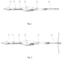
- the tandem-cumulative shot consists of a composite housing where the forearm 1 and the main cumulative warhead 2 are located, and an auxiliary jet engine 3 is set among them, by being connected to the primary cumulative warhead 2 by means of a bottom coupling element 4, preferably a bottom coupling bushing, and a drive unit, consisting of a primary jet engine 5 and a starter gunpowder charge 6 connected thereto with a stabilizer, which is connected to the rear part of the primary cumulative warhead.
- the cumulative forearm 1 includes a small-scale low-frequency cumulative unit to the auxiliary jet engine 3 is mounted to; at the rear end of it the bottom coupling bushing 4 is located, and the main warhead 2 is fixed to it.
- the bottom bushing 4 has an external form allowing it to absorb the energy of the detonated products of the cumulative forearm 1 and of the active elements of the armor, while simultaneously launching the blasting device 26 of the primary cumulative warhead 2.
- the cumulative forearm 1 is filled with a caliber up to 60 mm and consists of a blasting device 7 located in its front part, for example a piezo-generator connected to a current-conducting element 9 hosted in a fairing 8; we advise the conductor element 9 and the fairing 8 to be of conical shape.
- the fairing 8 is rigidly coupled to a conical-cylindrical housing; there is a cumulative unit with a cumulative funnel lining 10 with a conductor in its chamber.
- the lining is filled with a variable wall thickness progressively increasing from the top to the base in the range of 0.8 to 1.3 mm, and a diameter of not more than 48 mm and a height of not more than 39 mm.
- an explosive 12 In the chamber of the cumulative unit, there are an explosive 12 and a bottom blasting device 13 with a detonator located. It is preferable to use explosive 12 with parameters: a mass of 0.160 to 0.168kg; density of 1.76 to 1.8g/cm 3 ; a detonation speed rate equal to or greater than 8,000 m/s.
- the screen 11 of the forearm 1 Between the cumulative lining 10 and the detonator of the bottom blasting device 13, there is the screen 11 of the forearm 1; it is suitable to be made in a conical-spherical shape, and have the provision of a central hole passing through it - so the conductor can pass from the cumulative lining 10 and it is connected to the switch of the bottom blasting device 13.
- the screen 11 is compressed into the explosive substance 12 of the said cumulative unit.
- the screen 11 should be made of an inert material and its purpose is to deform the front of the detonation wave formed upon the launch of the explosive substance 12 in such a way that the formed front shall approach and progress along the profile of the outer forming of the cumulative funnel 10, dynamically deforming it, and thus facilitating and assisting in the formation of a low-grade cumulative jet flow of the cumulative unit.
- a characteristic feature of the forearm 1 is that the blasting device 7 of the forearm 1 is shaped under a spherical face surface, and it allows - after the submission of the detonation impulse from the bottom blasting device 13 to the explosive substance 12 - to form cumulative jet flow of a low gradient along its length.
- the formation of a low-grade cumulative jet flow provides the deactivation of the additionally mounted dynamic protective devices using different sources of energy, for example explosive substance, electrical power, energy generated by the reaction of active chemical substances, etc.
- a bilge block 14 mounted, and there is the auxiliary jet engine 3 mounted fast on it - and the engine 3 consists of a housing 15 of the auxiliary jet engine 3, where jet engine fuel 16 is stored.
- the pyro-delay-igniter 17 and the bottom 18 of the auxiliary jet engine 3 are located in the rear end of the jet engine 3 - this is, in its essence, a coupling element between the auxiliary jet engine 3 and the primary cumulative warhead 2.
- the bottom 18 is formed as a shaped element, for example a bushing, of cylindrical shape and a center hole threaded in it, and in a blasting device 19 of the primary warhead 2 is mounted in it.
- the bottom 18 is made in a way so that its middle and outer parts, especially in weakened section ( Fig.4 ), are filled with a small wall thickness.
- This constructive profile formation of the bottom 18 allows it to perform the function of a protective diaphragm, i.e. acting as a delay device, and its deformation in the said section allows the launch of the primary cumulative warhead 2 against the cumulative forearm 1 with a delay of 200-250 ⁇ s.
- the protective diaphragm is located at a distance from a cumulative funnel lining 23 with a conductor of the primary forehead 2, thus resulting in creating a space where the cumulative jet flow of the primary forehead 2 is formed, and it is not affected nor influenced by the products the forearm 1 or the active elements of the armor.
- the bulletproof-ness of the forearm 1 on homogeneous armored steel is not less than 300 mm.
- a conically shaped cavity is formed into the protective diaphragm and the coupling cone 20 of the primary warhead 2, where a conically shaped conductive element 21 is accommodated, the latter is used to transmit an electrical impulse generated by the piezoelectric blasting device 19 towards the cumulative funnel lining 23 with a conductor, or to the bottom blasting device 26 of the primary warhead 2, respectively.
- the primary cumulative warhead 2 consists of a cumulative unit and a front blasting device 19, preferably a piezo-generator, connected by means of a coupling cone 20 to a housing 22 of the primary warhead 2.
- the housing 22 accommodates: the conductive electrical element 21, the cumulative funnel lining 23 with a conductor, the explosive substance 24 of the primary warhead 2, and the screen 25 of the primary warhead 2 is housed behind the explosive.
- the coupling cone 20 is fast connected to the housing 22 preferably made in a cylindrical conical shape - and its inner chamber hosts the cumulative unit with a conical funnel lining 23 with an angle of opening of 60°, with a variable wall thickness progressively increasing from the top to the base from 0.8 to 2.2 mm, and the height being less than or equal to 78 mm, and the diameter of the cylindrical part - less than or equal to 94.5 mm, and the height of the cylindrical part - of up to 4.5 mm.
- the mass of explosive substance 20 shall be from 0.650 to 0.680 kg, and of density of not less than 1,8 g/cm 3 , with a detonation velocity of more than 8000 m/s.
- the bottom blasting device 26 of the primary warhead 2 is located at the rear part of the housing 22, the bottom blasting device 26 of the primary warhead 2 is located.
- the cumulative unit elements described here have been designed and constructed in a manner allowing - after the launch of cumulative unit - to form a high-speed cumulative jet flow, which provides the destruction of the homogeneous armor of thickness of more than 700 mm behind the active elements of the armored vehicle.
- the primary warhead 2 should preferably have a caliber smaller than or equal to 105 mm and should consist of a protective diaphragm located in the front, and not shown in the figures.
- the primary jet engine 5 is constructed in a cylindrical-conical shape, it consists of a bilge block 14' and a conical-cylindrical housing 27 ( Fig.5 ), located behind the block; the housing stores the fuel of the jet engine and the pyro-delay-igniter 17', contacting the bottom 28 of the primary jet engine 5.
- the bottom 28 - in its front part - has a flat vertically oriented surface and is arranged in a way as to close the combustion chamber of the primary jet engine 5, and at the same time it contains the combustion unit of the engine 5 consisting of an L-shaped hole in the bottom 28 having a strewing of black gunpowder smoke/smog 29 and a cartridge igniter 31.
- the geometric parameters and the configuration of the screening element 25 are in accordance with its functional purpose and in combination with the configuration of the cumulative lining 23, the housing 22, the type of the explosive substance 24, its energy parameters and their mutual location, deform and manage the front of the detonation wave generated by the detonation of the explosive substance 24.
- the blasting device 26 of the primary warhead 2 should be preferably constructed as piezoelectric and it is designed - while deforming the bottom bushing 6 of the auxiliary jet engine 3 in the weakened section, to generate an electrical impulse.
- the front part of the blasting device 19 should be made with a flat front and have it located at a predetermined distance from the convex inner cylindrical part of the bottom bushing 28, for example at a distance of 3-5 mm, having its convex inner cylindrical part pressing the front of the blasting device 19, while the electrical impulse generated by it is transmitted along the electrical circuit of the bottom part of the blasting device 26.
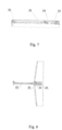
- the start gunpowder engine 6 consists of a stem 32 preferably made as a cylindrical body with a lot of radially oriented openings, while a powder bag, for example, black smoke gunpowder 29 is located in the inner surface of the stem 32 along its length, designed to ignite the primary charge, e.g. a tape-type nitroglycerine gunpowder, arranged around the nibs 35 of the stabilizer 5.
- a support member mounted not shown in the figures - and four nibs 33 are attached to it by means of hinges.
- the nibs 33 open from their collapsed position to 90 0 in the vertical position - under the centrifugal forces and countercurrent airflow.
- a turbine 34 is mounted, made in a cylindrical spiral shape, and a tracer 35 is mounted in the rear and inner part - to control the trajectory of the shot.
- the combustion of the black smoke gunpowder and the tapes of nitroglycerine gunpowder in the gunpowder start charge 6 provides a reactive force that propels and triggers the shot forward with an initial velocity of at least 70 m/s.
- Typical for the turbine 34 is its constructional design, particularly with respect to the length and the area of the ribs, formed by a helical line and designed so that when the tandem shot takes off of the grenade, the necessary angular velocity of 7.8 rotations/sec is ensured, achieved by the discharge of the gunpowder gases through the cross section of the turbine 34, these gases swirl around the helical line of the ribs, thereby creating a rotational movement of the shot in the grenade.
- the angular velocity of the shot is needed, on the one hand, to create a centrifugal force that allows the four stabilizer nibs 33 to be opened after the shot has been fired from the grenade launcher at a certain distance, which in turn is necessary to create a lifting force, against the drop of the shot at the initial stage of the flight path trajectory, in particular by the time of the inclusion of the auxiliary 3 and the primary 5 jet engines.
- maintaining the said angular velocity is necessary in order to stabilize the shot flight, along its trajectory until it meets the barrier.
- the auxiliary jet engine 3, located between the forearm 1 and the primary cumulative warhead 2 will have a reduced overall size, approximately half that of the primary jet engine 5, and it shall respectively reflect the energy properties and the action time of the reactive power and thrust each of the two engines 3 and 5 creates. This practically predetermines the performance of the two engines to be different whereas the combustion time of the auxiliary jet engine 3 is approximately 0.3 s, while the primary engine 5 has approx. 0.7 s.
- tandem-cumulative shot there is a provision for the use of the same primary 5 and auxiliary 3 jet engines as construction and technical parameters, which may differ only in the length of the casing and the fuel 30, made as a cylindrical nitroglycerine cartridge, especially along the cylindrical cartridge and along the construction of the bottom bushing 4 of the auxiliary jet engine 3, which has several functional uses, such as: acting as a closing element of the chamber of the auxiliary jet engine 3, as well as to join the auxiliary jet engine 3 and the primary cumulative warhead 2.
- the angular velocity of the shot along its trajectory is maintained thanks to the profile of the four nibs 33, made with one-sided tangential gradient, resulting - due to the air countercurrent - in a swirling motion and maintaining the angular velocity along the trajectory.
- the stabilizer constructed so that the maximum width of the nibs 33 in the open position is 437-450 mm, and the total length of the stabilizer is from 290 to 292.5 mm, while the nibs 33 are constructively ensured to have a maximum contact area.
- tandem-cumulative shot described herein with two jet engines 3 and 5 and a gunpowder starting charge 6 with a stabilizer can be presented as follows: after placing the tandem-cumulative shot in the grenade launcher and producing a shot, as a result of the gases formed by the gunpowder starting charge 6, a reactive force is formed and it propels the tandem-cumulative shot forward. Upon discharge of the so formed gunpowder gases through the helical section of the turbine 34, the shot is transmitted to a rotary motion with an angular velocity of 7..8 rotations per second and an initial take-off speed from the grenade mouth not less than 70 m/s.
- the four nibs 33 of the stabilizer 6 are opened under the operation of the centrifugal forces and countercurrent airflow. Approximately up to 12 meters from the start of the shot trajectory, the operation of the inertial and pyrotechnic safety mechanisms of the bottom blasting devices of the forearm and the primary warhead are completed, resulting in the tandem-cumulative shot being ready to encounter the target.
- the pyro-delay-ignition devices 17, 17' of the two jet engines 3 and 5 are triggered, and then - under the operation of the reactive forces, the shot accelerates and maintains a march velocity for the shot to reach the target and have the latter damaged by the tandem warhead.
- the operation of the two jet engines 3 and 5 is parallel, with the auxiliary jet engine 3 running approximately 0.3 ... 0.34 s, while the second one runs 0.7... 074 s in the temperature range of -50 0 C to + 50 0 C; by observing these parameters this ensures a straight shot can be made at a distance of not less than 300 m.
- the piezo-generator 7 of the forearm 1 When the tandem-cumulative shot encounters with a barrier, the piezo-generator 7 of the forearm 1 generates an electrical impulse transmitted - along the electric circuit - to the spark electro-detonator (not shown in the figures) of the bottom blasting device 13 further delivering a detonating impulse to the explosive substance 12 of the cumulative charge.
- the spherical front of the detonation wave thus formed spreads over the bursting charge by passing through the cone-spherical form of the screen 11, thereby altering its shape and parameters.
- the formed new detonation wave front fits closely to the cumulative lining 10 profile, dynamically deforming it and forming a cumulative jet flow of a low gradient of the velocity along its length.
- the formed low-grade cumulative jet flow interacts with the active elements of the armor, by triggering and deactivating them. Parallel to it, the energy released by the detonation products of the forearm 1, the active elements of the armor and the mechanical shock wave impact the cross section of the bilge block 14 of the auxiliary jet engine 3, thus deforming the bottom sleeve 4 in the n/n section.
- the formed spherical front of the detonation wave spreads along the bursting charge, bypassing the cone-spherical form of the screen 25, thereby altering its shape and parameters.
- the newly formed detonation wave front fits closely to the profile of the cumulative lining 23, dynamically deforming it and forming a high-speed cumulative jet flow that interacts with the target - the main armor of the armored vehicle.
- Forming of high-speed cumulative jet flow ensures the striking of the homogeneous armor with a thickness of not less than 700 mm, located behind the active elements of the armored vehicle.
- the delaying action of the primary warhead 2 in relation to the forearm 1 is determined by the sum of the times for the launching of the blasting device 13 of the forearm 1, the formation of the cumulative jet flow and its interaction with the dynamic elements of the armor, the dynamic deformation of the bottom bushing 4 of the auxiliary jet engine, the launch of the primary warhead 2, the formation of a high-speed cumulative jet flow, and its interaction with the main armor of the armored vehicle, the total sum of the time being in the range of 250-300 ⁇ s.
Description
- The invention refers to a tandem-cumulative Shot equipped with two jet engines and a gunpowder starter motor with a stabilizer, designed to defeat all types of armored equipment, including one equipped with passive armor, additionally mounted dynamic-type protective devices using various sources of energy, for example explosive, electrical energy, energy obtained from the reaction of active chemical substances, etc.).
- There are tandem combat units known to be used to defeat armored machinery and other enemy objects.
A tandem-cumulative ammunition is known, being the subject of PatentUS5415105 , whose structure includes a housing with a primary cumulative charge fitted in it with a cumulative concavity oriented toward the front of the housing. - Patent publication
DE3942841 is known, disclosing a tandem munition where the primary charge has a piezoelectric impact blower, which contains a contact/impact shock sensor, designed to generate the ignition voltage of the detonator. The ignition voltage of the detonator occurs when, in a collision with the target, the emerging shock wave triggers the contact impact sensor. In the structure described, the piezo-elements in the impact blower are used as sensors. -
- There is a tandem-cumulative warhead known, subject of
BG 63851 B1 - The disadvantage of the invention is the small distance between the forearm and the primary warhead, as a result of which the detonation products of the forearm have a significant, dominant influence on the time and the manner of forming the cumulative jet flow caused by the actuation of the primary cumulative charge.
- Given the state - described and known - of the equipment in the area under consideration, the invention task is to provide a sophisticated universal tandem-cumulative shot of a simplified and manufacturing-friendly design that provides effective combat action against armored equipment including those equipped with passive armor, additionally mounted dynamic-type protective devices and other objects and facilities of the enemy.
- The problem is solved by the tandem-cumulative shot as defined by
claim 1. It comprises a composite housing, said composite housing hosting in its front part a forearm and a primary warhead, wherein the forearm comprises a cumulative warhead and an auxiliary jet engine between the cumulative warhead and the primary warhead, whereby the auxiliary jet engine is connected to the primary warhead by means of a bottom bushing, whereby the cumulative warhead and the primary warhead are equipped with identical piezo-electric front and bottom blasting devices, wherein, at the rear end of the primary warhead, a drive unit consisting of a primary jet engine and a gunpowder starting charge with a stabilizer is mounted. - According to the invention, inside the primary warhead, the piezo-electric front blasting device of the primary warhead is located which is connected by an electrical connection to the piezo-electric bottom blasting device of the primary warhead,
- wherein the piezoelectric front blasting device of the forearm is connected to the piezo-electric bottom blasting device of the forearm by means of an electrical connection and whereby the piezo-electric front blasting device of the forearm is mounted in the front part of the forearm;
- wherein the front blasting device of the forearm is shaped under a spherical face surface.
- wherein the gunpowder starting charge with a stabilizer having a stem inside of which flat, tangentially tapering nibs are mounted using hinges,
- wherein a turbine with ribs formed in a helical line is mounted behind the stabilizer.
- According to a preferred execution of the tandem-cumulative shot the forearm and the main warhead are located co-axially.
- According to one execution manner of the tandem-cumulative shot, the bottom coupling bushing is cylindrical in shape with a variable shape and wall thickness, while the middle and the outer part have a minimum wall thickness in the weakened section.
- The bottom bushing in its one end has a thick wall on its end - and the wall is convex to its inner side, in the form of a cylinder, and is located at a distance 3-5 mm of the piezoelectric blasting device of the primary warhead.
- According to one variant execution of the tandem-cumulative shot, the connection between the forearm and the auxiliary jet engine is rigid, and the connection between the bottom bushing and the primary cumulative warhead is deformable. The connection between the primary cumulative warhead, the primary jet engine and the starting gunpowder charge is rigid.
- The bottom of the auxiliary jet engine is shaped as a cylindrical body, with a concentrator formed between the outer and the inner profile in the weakened section.
- The forearm with a caliber of less than or equal to 60 mm consists of a piezo-generator connected to a current conducting element housed in the fairing with a conical shape, wherein the fairing is fixedly connected to a conical-cylindrical housing in whose chamber the cumulative unit is located.
- The screen is made in a conical-spherical shape with a central opening a conductor of the cumulative lining passes through, further connected to contact the bottom blasting device. The forearm consists of a blasting device connected to a conductor element housed in a cowl of a conical shape, wherein the cowl is rigidly connected to a conical-cylindrical housing where a cumulative unit is housed in its chamber.
- The cumulative lining has a variable wall thickness progressively increasing from the top to the base.
- The screen element is compressed into the explosive substance and located between the cumulative lining and the bottom blasting device, wherein the screen has a conical-spherical shape, with an opening in the center, and a conductor of the cumulative lining connected to the top contact of the bottom blasting device passes through. It is recommendable to have the screen made of an inert material and compressed into the explosive substance of the cumulative unit.
- The primary warhead has a caliber of up to 105 mm and consists of a diaphragm with a central aperture, and the front part of the piezoelectric blasting device is mounted to it, connected by an electrically conductive element housed within the inner space of the coupling cone, a cylindrical-conical shaped housing. There is a cumulative unit in its inner chamber, consisting of a cylindrical-conical lining with an opening angle of 60° and a variable wall thickness progressively increasing from the top to the base.
- The main warhead screen is biased into the explosive and disposed between the cumulative lining and the bottom blasting device, made in a conical-spherical shaped and having a central opening, the cumulative lining conduit connected to the upper switch of the bottom blasting device passes through.
- The auxiliary jet engine and the primary jet engine are of different lengths of their housings and have been equipped with identical bilge blocks and pyro-flammable-ignition devices.
- Flat, tangentially oblique feathers are hinged to the rear of the starter gunpowder charge, and a turbine with ribs formed in a helical line is mounted behind the stabilizer.
- The tandem-cumulative shot has significant advantages in terms of simplified technological design and improved effectiveness in terms of target damage. Including into the construction of an auxiliary jet engine located between the forearm and the primary cumulative warhead brings additional reactive power and allows striking targets at a further distance, as the constructive solution of the shot, subject of the invention provides protection for the main warhead from the detonation products of the forearm and the active elements of the armor and, at the same time, by the suitably chosen constructing design of the bottom coupling bushing of the auxiliary jet engine, it provides timely launch of the piezo-generated blasting device the main warhead. The described addition of the auxiliary jet engine provides protection of the main warhead from detonation products of the cumulative unit of the forearm and the active elements of the armor, thus constructively providing sufficient space to form the cumulative jet flow of the primary charge.
- The above-mentioned technical effects are due to a considerable extent to the predicted constructive connection between the preliminary cumulative charge and the auxiliary jet engine that is suitable to be a rigid connection, as these properties allow to bear the deformation effects of the contact action in generating an electrical impulse from the piezo-generated blasting device and its launch, the impact of the detonation products of the forearm and the active elements of the armor. The achieved technical effect is also due to the used deformable element located in the bottom bushing construction of the auxiliary jet engine and the main warhead, as a result of which the aforesaid deformable element absorbs the produced energy from the contact action, the impact of the detonation products of the forearm and the active elements of the armor, as this deformation basically also provides the launch of the piezo-generator of the main warhead.
- Another advantage of the tandem-cumulative charge, according to the invention, is the improved shot-path parameters - their increased initial and angular velocity as well as the flight path stabilization are mainly due to the connection between the main warhead to the primary jet engine and the gunpowder start charge, whose hardness creates a whole unified unit.
- The starter gunpowder engine launches a tandem-cumulative shot from a grenade launcher, whereby, thanks to the positioned stabilizer behind the main warhead, the firing path of the shot stabilizes along its trajectory, while the jet engines accelerate the shot along the trajectory. After the blasting device has been launched by the primary warhead, a cumulative jet flow is formed upon encountering the barrier and it interacts with the main armor of the armored vehicle.
- Further, a possible detailed example is provided, illustrated by the accompanying figures, wherein:
- Fig. 1 -
- General view of the tandem-cumulative shot, subject of the invention
- Fig. 2 -
- General view of the tandem-cumulative shot in flight mode
- Fig. 3 -
- General view with a partial section of a tandem-cumulative shot with an auxiliary jet engine, located between the forearm and the main warhead.
- Fig. 4 -
- General view with a partial section of the auxiliary jet engine
- Fig. 5 -
- General view with a partial section of the primary jet engine
- Fig. 6 -
- Displaying the device of launching the main warhead
- Fig. 7 -
- Displaying the start gunpowder charge with a stabilizer
- Fig. 8 -
- Displaying the start charge with a stabilizer
- The tandem-cumulative shot, according to the invention, consists of a composite housing where the
forearm 1 and the main cumulative warhead 2 are located, and an auxiliary jet engine 3 is set among them, by being connected to the primary cumulative warhead 2 by means of abottom coupling element 4, preferably a bottom coupling bushing, and a drive unit, consisting of a primary jet engine 5 and a starter gunpowder charge 6 connected thereto with a stabilizer, which is connected to the rear part of the primary cumulative warhead. - The
cumulative forearm 1 includes a small-scale low-frequency cumulative unit to the auxiliary jet engine 3 is mounted to; at the rear end of it thebottom coupling bushing 4 is located, and the main warhead 2 is fixed to it. Thebottom bushing 4 has an external form allowing it to absorb the energy of the detonated products of thecumulative forearm 1 and of the active elements of the armor, while simultaneously launching the blasting device 26 of the primary cumulative warhead 2. - According to an exemplary production work of the invention, the
cumulative forearm 1 is filled with a caliber up to 60 mm and consists of a blasting device 7 located in its front part, for example a piezo-generator connected to a current-conducting element 9 hosted in a fairing 8; we advise the conductor element 9 and the fairing 8 to be of conical shape. The fairing 8 is rigidly coupled to a conical-cylindrical housing; there is a cumulative unit with a cumulative funnel lining 10 with a conductor in its chamber. The lining is filled with a variable wall thickness progressively increasing from the top to the base in the range of 0.8 to 1.3 mm, and a diameter of not more than 48 mm and a height of not more than 39 mm. - In the chamber of the cumulative unit, there are an explosive 12 and a
bottom blasting device 13 with a detonator located. It is preferable to use explosive 12 with parameters: a mass of 0.160 to 0.168kg; density of 1.76 to 1.8g/cm3; a detonation speed rate equal to or greater than 8,000 m/s. Between thecumulative lining 10 and the detonator of thebottom blasting device 13, there is the screen 11 of theforearm 1; it is suitable to be made in a conical-spherical shape, and have the provision of a central hole passing through it - so the conductor can pass from thecumulative lining 10 and it is connected to the switch of thebottom blasting device 13. - According to a preferred execution manner, the screen 11 is compressed into the
explosive substance 12 of the said cumulative unit. The screen 11 should be made of an inert material and its purpose is to deform the front of the detonation wave formed upon the launch of theexplosive substance 12 in such a way that the formed front shall approach and progress along the profile of the outer forming of thecumulative funnel 10, dynamically deforming it, and thus facilitating and assisting in the formation of a low-grade cumulative jet flow of the cumulative unit. - A characteristic feature of the
forearm 1 is that the blasting device 7 of theforearm 1 is shaped under a spherical face surface, and it allows - after the submission of the detonation impulse from thebottom blasting device 13 to the explosive substance 12 - to form cumulative jet flow of a low gradient along its length. The formation of a low-grade cumulative jet flow provides the deactivation of the additionally mounted dynamic protective devices using different sources of energy, for example explosive substance, electrical power, energy generated by the reaction of active chemical substances, etc. - Near the rear end of the
cumulative forearm 1, after the bottom-blastingdevice 13, there is abilge block 14 mounted, and there is the auxiliary jet engine 3 mounted fast on it - and the engine 3 consists of a housing 15 of the auxiliary jet engine 3, wherejet engine fuel 16 is stored. The pyro-delay-igniter 17 and the bottom 18 of the auxiliary jet engine 3 are located in the rear end of the jet engine 3 - this is, in its essence, a coupling element between the auxiliary jet engine 3 and the primary cumulative warhead 2. - The bottom 18 is formed as a shaped element, for example a bushing, of cylindrical shape and a center hole threaded in it, and in a
blasting device 19 of the primary warhead 2 is mounted in it. According to a preferred execution manner of the utility model, the bottom 18 is made in a way so that its middle and outer parts, especially in weakened section (Fig.4 ), are filled with a small wall thickness. This constructive profile formation of the bottom 18 allows it to perform the function of a protective diaphragm, i.e. acting as a delay device, and its deformation in the said section allows the launch of the primary cumulative warhead 2 against thecumulative forearm 1 with a delay of 200-250 µs. The protective diaphragm is located at a distance from a cumulative funnel lining 23 with a conductor of the primary forehead 2, thus resulting in creating a space where the cumulative jet flow of the primary forehead 2 is formed, and it is not affected nor influenced by the products theforearm 1 or the active elements of the armor. The bulletproof-ness of theforearm 1 on homogeneous armored steel is not less than 300 mm. - A conically shaped cavity is formed into the protective diaphragm and the
coupling cone 20 of the primary warhead 2, where a conically shaped conductive element 21 is accommodated, the latter is used to transmit an electrical impulse generated by thepiezoelectric blasting device 19 towards the cumulative funnel lining 23 with a conductor, or to the bottom blasting device 26 of the primary warhead 2, respectively. - The primary cumulative warhead 2 consists of a cumulative unit and a
front blasting device 19, preferably a piezo-generator, connected by means of acoupling cone 20 to a housing 22 of the primary warhead 2. The housing 22 accommodates: the conductive electrical element 21, the cumulative funnel lining 23 with a conductor, theexplosive substance 24 of the primary warhead 2, and the screen 25 of the primary warhead 2 is housed behind the explosive. Thecoupling cone 20 is fast connected to the housing 22 preferably made in a cylindrical conical shape - and its inner chamber hosts the cumulative unit with a conical funnel lining 23 with an angle of opening of 60°, with a variable wall thickness progressively increasing from the top to the base from 0.8 to 2.2 mm, and the height being less than or equal to 78 mm, and the diameter of the cylindrical part - less than or equal to 94.5 mm, and the height of the cylindrical part - of up to 4.5 mm. Preferably, the mass ofexplosive substance 20 shall be from 0.650 to 0.680 kg, and of density of not less than 1,8 g/cm3, with a detonation velocity of more than 8000 m/s. At the rear part of the housing 22, the bottom blasting device 26 of the primary warhead 2 is located.
The cumulative unit elements described here have been designed and constructed in a manner allowing - after the launch of cumulative unit - to form a high-speed cumulative jet flow, which provides the destruction of the homogeneous armor of thickness of more than 700 mm behind the active elements of the armored vehicle. - The primary warhead 2 should preferably have a caliber smaller than or equal to 105 mm and should consist of a protective diaphragm located in the front, and not shown in the figures.
- According to a preferred embodiment manner of the tandem-cumulative shot, the primary jet engine 5 is constructed in a cylindrical-conical shape, it consists of a bilge block 14' and a conical-cylindrical housing 27 (
Fig.5 ), located behind the block; the housing stores the fuel of the jet engine and the pyro-delay-igniter 17', contacting the bottom 28 of the primary jet engine 5. The bottom 28 - in its front part - has a flat vertically oriented surface and is arranged in a way as to close the combustion chamber of the primary jet engine 5, and at the same time it contains the combustion unit of the engine 5 consisting of an L-shaped hole in the bottom 28 having a strewing of black gunpowder smoke/smog 29 and acartridge igniter 31. - The geometric parameters and the configuration of the screening element 25 are in accordance with its functional purpose and in combination with the configuration of the cumulative lining 23, the housing 22, the type of the
explosive substance 24, its energy parameters and their mutual location, deform and manage the front of the detonation wave generated by the detonation of theexplosive substance 24. - The blasting device 26 of the primary warhead 2 should be preferably constructed as piezoelectric and it is designed - while deforming the bottom bushing 6 of the auxiliary jet engine 3 in the weakened section, to generate an electrical impulse. Preferably, the front part of the
blasting device 19 should be made with a flat front and have it located at a predetermined distance from the convex inner cylindrical part of thebottom bushing 28, for example at a distance of 3-5 mm, having its convex inner cylindrical part pressing the front of theblasting device 19, while the electrical impulse generated by it is transmitted along the electrical circuit of the bottom part of the blasting device 26. - The start gunpowder engine 6 consists of a
stem 32 preferably made as a cylindrical body with a lot of radially oriented openings, while a powder bag, for example, black smoke gunpowder 29 is located in the inner surface of thestem 32 along its length, designed to ignite the primary charge, e.g. a tape-type nitroglycerine gunpowder, arranged around thenibs 35 of the stabilizer 5. At the rear of the starter gunpowder charge with a stabilizer 6, there is a support member mounted not shown in the figures - and fournibs 33 are attached to it by means of hinges. Upon having the tandem shot take-off from the grenade launcher, thenibs 33 open from their collapsed position to 900 in the vertical position - under the centrifugal forces and countercurrent airflow. At the rear of the starter charge 6, aturbine 34 is mounted, made in a cylindrical spiral shape, and atracer 35 is mounted in the rear and inner part - to control the trajectory of the shot. The combustion of the black smoke gunpowder and the tapes of nitroglycerine gunpowder in the gunpowder start charge 6 provides a reactive force that propels and triggers the shot forward with an initial velocity of at least 70 m/s. - Typical for the
turbine 34 is its constructional design, particularly with respect to the length and the area of the ribs, formed by a helical line and designed so that when the tandem shot takes off of the grenade, the necessary angular velocity of 7.8 rotations/sec is ensured, achieved by the discharge of the gunpowder gases through the cross section of theturbine 34, these gases swirl around the helical line of the ribs, thereby creating a rotational movement of the shot in the grenade. The angular velocity of the shot is needed, on the one hand, to create a centrifugal force that allows the fourstabilizer nibs 33 to be opened after the shot has been fired from the grenade launcher at a certain distance, which in turn is necessary to create a lifting force, against the drop of the shot at the initial stage of the flight path trajectory, in particular by the time of the inclusion of the auxiliary 3 and the primary 5 jet engines. At the same time, maintaining the said angular velocity is necessary in order to stabilize the shot flight, along its trajectory until it meets the barrier. It has been constructively designed the auxiliary jet engine 3, located between theforearm 1 and the primary cumulative warhead 2, will have a reduced overall size, approximately half that of the primary jet engine 5, and it shall respectively reflect the energy properties and the action time of the reactive power and thrust each of the two engines 3 and 5 creates. This practically predetermines the performance of the two engines to be different whereas the combustion time of the auxiliary jet engine 3 is approximately 0.3 s, while the primary engine 5 has approx. 0.7 s. - According to a preferred embodiment manner of the tandem-cumulative shot, there is a provision for the use of the same primary 5 and auxiliary 3 jet engines as construction and technical parameters, which may differ only in the length of the casing and the
fuel 30, made as a cylindrical nitroglycerine cartridge, especially along the cylindrical cartridge and along the construction of thebottom bushing 4 of the auxiliary jet engine 3, which has several functional uses, such as: acting as a closing element of the chamber of the auxiliary jet engine 3, as well as to join the auxiliary jet engine 3 and the primary cumulative warhead 2. - In order to ensure the beneficial effect as well as the technological simplification of the structure as a whole, it is appropriate to use matching bilge blocks 14, 14" as well as matching pyro-
delay ignition devices - The angular velocity of the shot along its trajectory is maintained thanks to the profile of the four
nibs 33, made with one-sided tangential gradient, resulting - due to the air countercurrent - in a swirling motion and maintaining the angular velocity along the trajectory. - For the purpose of providing a stable shot flight path, it is suitable to have the stabilizer constructed so that the maximum width of the
nibs 33 in the open position is 437-450 mm, and the total length of the stabilizer is from 290 to 292.5 mm, while thenibs 33 are constructively ensured to have a maximum contact area. - The use of the tandem-cumulative shot described herein with two jet engines 3 and 5 and a gunpowder starting charge 6 with a stabilizer can be presented as follows: after placing the tandem-cumulative shot in the grenade launcher and producing a shot, as a result of the gases formed by the gunpowder starting charge 6, a reactive force is formed and it propels the tandem-cumulative shot forward. Upon discharge of the so formed gunpowder gases through the helical section of the
turbine 34, the shot is transmitted to a rotary motion with an angular velocity of 7..8 rotations per second and an initial take-off speed from the grenade mouth not less than 70 m/s. Moving forwardly, under the operation of the reactive force, linear inertial forces arise and they trigger the inertial mechanisms of the pyro-delay-ignition mechanisms bottom blasting devices 13 and 26, of theforearm 1 and the primary cumulative warhead 2 respectively are triggered, too. - After firing the shot from the grenade launcher, the four
nibs 33 of the stabilizer 6 are opened under the operation of the centrifugal forces and countercurrent airflow. Approximately up to 12 meters from the start of the shot trajectory, the operation of the inertial and pyrotechnic safety mechanisms of the bottom blasting devices of the forearm and the primary warhead are completed, resulting in the tandem-cumulative shot being ready to encounter the target. - In the initial section of the shot trajectory, the pyro-delay-
ignition devices 17, 17' of the two jet engines 3 and 5 are triggered, and then - under the operation of the reactive forces, the shot accelerates and maintains a march velocity for the shot to reach the target and have the latter damaged by the tandem warhead. - The operation of the two jet engines 3 and 5 is parallel, with the auxiliary jet engine 3 running approximately 0.3 ... 0.34 s, while the second one runs 0.7... 074 s in the temperature range of -500C to + 500C; by observing these parameters this ensures a straight shot can be made at a distance of not less than 300 m.
- When the tandem-cumulative shot encounters with a barrier, the piezo-generator 7 of the
forearm 1 generates an electrical impulse transmitted - along the electric circuit - to the spark electro-detonator (not shown in the figures) of thebottom blasting device 13 further delivering a detonating impulse to theexplosive substance 12 of the cumulative charge. The spherical front of the detonation wave thus formed spreads over the bursting charge by passing through the cone-spherical form of the screen 11, thereby altering its shape and parameters. The formed new detonation wave front fits closely to thecumulative lining 10 profile, dynamically deforming it and forming a cumulative jet flow of a low gradient of the velocity along its length. The formed low-grade cumulative jet flow interacts with the active elements of the armor, by triggering and deactivating them. Parallel to it, the energy released by the detonation products of theforearm 1, the active elements of the armor and the mechanical shock wave impact the cross section of thebilge block 14 of the auxiliary jet engine 3, thus deforming thebottom sleeve 4 in the n/n section. - With the deformation of the bottom 4 in the weakened section, the distance between the convex inner part of the
bottom sleeve 4 and the piezo-generator 7 of the primary cumulative warhead 2 is overcome and thereby an electric pulse is deformed and generated transmitted by an electric circuit to the spark electric detonator (not displayed on the figures) of the bottom blasting device 26, thus resulting in forwarding a detonation impulse to theexplosive substance 24 on the primary cumulative warhead 2. - The formed spherical front of the detonation wave spreads along the bursting charge, bypassing the cone-spherical form of the screen 25, thereby altering its shape and parameters. The newly formed detonation wave front fits closely to the profile of the cumulative lining 23, dynamically deforming it and forming a high-speed cumulative jet flow that interacts with the target - the main armor of the armored vehicle.
- Forming of high-speed cumulative jet flow ensures the striking of the homogeneous armor with a thickness of not less than 700 mm, located behind the active elements of the armored vehicle.
- The delaying action of the primary warhead 2 in relation to the
forearm 1 is determined by the sum of the times for the launching of theblasting device 13 of theforearm 1, the formation of the cumulative jet flow and its interaction with the dynamic elements of the armor, the dynamic deformation of thebottom bushing 4 of the auxiliary jet engine, the launch of the primary warhead 2, the formation of a high-speed cumulative jet flow, and its interaction with the main armor of the armored vehicle, the total sum of the time being in the range of 250-300 µs. - 1 -
- Forearm
- 2 -
- Primary cumulative warhead
- 3 -
- Auxiliary jet engine
- 4 -
- Coupling bottom (bottom bushing)
- 5 -
- Primary jet engine
- 6 -
- Starting gunpowder charge with a stabilizer
- 7 -
- Blasting device (piezo-generator) of the forearm (1)
- 8 -
- Fairing
- 9 -
- A conductive element
- 10 -
- Cumulative lining with a conductor of the forearm (1)
- 11 -
- Forearm (1) screen
- 12 -
- Explosive substance of the forearm (1)
- 13 -
- Bottom blasting device of the forearm (1)
- 14 -
- Bilge block
- 15 -
- Housing of the auxiliary jet engine (3)
- 16 -
- Fuel (nitroglycerin cartridge) of the auxiliary jet engine (3)
- 17 -
- Pyro-delay-igniter of the auxiliary jet engine (3)
- 18 -
- Auxiliary jet engine (3) bottom
- 19 -
- Blasting device (piezo-generator) of the primary warhead (2)
- 20 -
- Coupling cone of the primary warhead (2)
- 21 -
- Conical power-conducting element of the primary warhead (2)
- 22 -
- Housing of the primary warhead (2)
- 23 -
- A cumulative funnel with a conductor of the primary warhead (2)
- 24 -
- Explosive substance of the primary warhead (2)
- 25 -
- Primary warhead (1) screen
- 26 -
- Bottom blasting device of the primary warhead (2)
- 27 -
- Housing of the primary jet engine (5)
- 28 -
- Bottom of the primary jet engine (5)
- 29 -
- Strewing of black smoke gunpowder
- 30 -
- Fuel (nitroglycerin cartridge) of the primary jet engine (5)
- 31 -
- Capsule igniter of the primary jet engine
- 32 -
- Stem
- 33 -
- Nib of the Stabilizer
- 34 -
- Turbine
- 35 -
- Tracer.
Claims (13)
- A tandem cumulative shot comprising a composite housing, said composite housing hosting in its front part a forearm (1) and a primary warhead (2),wherein the forearm (1) comprises a cumulative warhead and an auxiliary jet engine (3) between the cumulative warhead and the primary warhead, whereby the auxiliary jet engine (3) is connected to the primary warhead (2) by means of a bottom bushing (4),whereby the cumulative warhead and the primary warhead (2) are equipped with identical piezo-electric front (7,19) and bottom (13, 26) blasting devices,wherein, at the rear end of the primary warhead (2), a drive unit consisting of a primary jet engine (5) and a gunpowder starting charge (6) with a stabilizer is mounted,wherein, inside the primary warhead (2), the piezo-electric front blasting device (19) of the primary warhead (2) is located which is connected by an electrical connection to the piezo-electric bottom blasting device (26) of the primary warhead (2),wherein the piezoelectric front blasting device (7) of the forearm (1) is connected to the piezo-electric bottom blasting device (13) of the forearm (1) by means of an electrical connection and whereby the piezo-electric front blasting device (7) of the forearm is mounted in the front part of the forearm (1),wherein the front blasting device (7) of the forearm (1) is shaped under a spherical face surface,wherein the gunpowder starting charge (6) with a stabilizer having a stem (32) inside of which flat, tangentially tapering nibs (33) are mounted using hinges,wherein a turbine (34) with ribs formed in a helical line is mounted behind the stabilizer.
- Tandem-cumulative shot according to claim 1, whereby the forearm (1) and the primary warhead (2) are located co-axially.
- Tandem-cumulative shot according to claim 1, whereby the bottom bushing (4) is cylindrical in shape with a variable shape and wall thickness, while the middle and the outer part have a minimum thickness of the wall in the weakened section.
- Tandem-cumulative shot according to claim 1, whereby the bottom bushing (4) in its one end has a thick wall on its end- and the wall is convex to its inner side, in the form of a cylinder, and is located at a distance 3-5 mm of the piezoelectric blasting device (19) of the primary warhead (2).
- Tandem-cumulative shot according to claim 1, whereby the connection between the forearm (1) and the auxiliary jet engine (3) is rigid, and the connection between the bottom bushing (4) and the primary cumulative warhead (2) is deformable.
- Tandem-cumulative shot according to claim 1, whereby the connection between the primary cumulative warhead (2), the primary jet engine (5) and the starting gunpowder charge (6) is rigid.
- Tandem-cumulative shot according to claim 1, whereby the forearm (1) with a caliber of less than or equal to 60 mm consists of a piezo-generator (7) connected to a current conducting element (9) housed in the fairing (8) with a conical shape, wherein the fairing (8) is fixedly connected to a conical-cylindrical housing in whose chamber the cumulative unit is located.
- Tandem-cumulative shot according to claim 1, whereby the cumulative lining (10) has a variable wall thickness progressively increasing from the top to the base.
- Tandem-cumulative shot according to claim 1, whereby the screen (11) is made in a conical-spherical shape with a central opening a conductor of the cumulative lining (10) passes through, further connected to contact the bottom blasting device (13).
- Tandem-cumulative shot according to claim 1, whereby the screen (11) is made of an inert material and is compressed into the explosive substance (12) of the cumulative unit.
- Tandem-cumulative shot according to claim 1, whereby the primary warhead (2) has a caliber of less than or equal to 105 mm, and consists of a diaphragm with an opening in the center, and the piezoelectric blasting device (19) is mounted to it, connected by means of a current-conducting element (21) housed in the inner space of the coupling cone (20) with a cylindrical conical shape housing (22), in whose inner chamber there is a cumulative unit located, consisting of a cylindrical-conical lining (23) with an angle of the opening of 600 and a variable wall thickness progressively rising from the top to the base.
- Tandem-cumulative shot according to claim 1, whereby the screen element (25) is compressed into the explosive substance (24) and located between the cumulative lining (23) and the bottom blasting device (26), made in a conical-spherical shape and an opening in the center where the conductor of the cumulative lining conductor (23), connected by contacting the bottom blasting device (26), passes through.
- Tandem-cumulative shot according to claim 1, whereby the auxiliary jet engine (3) and the primary jet engine (4) have different length of their housings (15) and (22), and have been equipped with identical bilge blocks (14, 14') and pyro-delay igniters (17, 17').
Applications Claiming Priority (2)
| Application Number | Priority Date | Filing Date | Title |
|---|---|---|---|
| BG390317 | 2017-11-08 | ||
| PCT/BG2018/000008 WO2019090399A1 (en) | 2017-11-08 | 2018-01-31 | Tandem-cumulative shot |
Publications (2)
| Publication Number | Publication Date |
|---|---|
| EP3714229A1 EP3714229A1 (en) | 2020-09-30 |
| EP3714229B1 true EP3714229B1 (en) | 2024-02-28 |
Family
ID=61244324
Family Applications (1)
| Application Number | Title | Priority Date | Filing Date |
|---|---|---|---|
| EP18705814.4A Active EP3714229B1 (en) | 2017-11-08 | 2018-01-31 | Tandem-cumulative shot |
Country Status (3)
| Country | Link |
|---|---|
| EP (1) | EP3714229B1 (en) |
| EA (1) | EA038130B1 (en) |
| WO (1) | WO2019090399A1 (en) |
Family Cites Families (9)
| Publication number | Priority date | Publication date | Assignee | Title |
|---|---|---|---|---|
| US2894457A (en) | 1955-03-18 | 1959-07-14 | Magnavox Co | Detonation delay device |
| NL257009A (en) | 1959-11-02 | 1900-01-01 | Energa | |
| DE3712697A1 (en) * | 1987-04-14 | 1990-07-05 | Diehl Gmbh & Co | Mortar projectile with additional explosive charge - is arranged so that centre of gravity of missile remains in constant position |
| DE3942841A1 (en) | 1989-12-23 | 1991-06-27 | Dynamit Nobel Ag | ADJUSTABLE SPACER ON A HIGH CHARGE HEAD, SWITCHABLE FOR DEPTH OR SIDE EFFECT |
| USH867H (en) * | 1990-07-23 | 1991-01-01 | The United States Of America As Represented By The Secretary Of The Army | Tandem warheads separated by missile booster motor |
| DE4240084A1 (en) | 1992-11-28 | 1994-06-01 | Dynamit Nobel Ag | Tandem warhead with piezoelectric impact fuses |
| SE507558C2 (en) * | 1995-01-23 | 1998-06-22 | Bofors Ab | Grenade with multi-charges |
| DE19827171A1 (en) * | 1998-06-18 | 1999-12-23 | Dynamit Nobel Ag | Weapon, especially anti-tank weapon |
| BG63851B1 (en) * | 1999-11-01 | 2003-03-31 | "Вмз" Еад | Tandem-hollow charge warhead |
-
2018
- 2018-01-31 EP EP18705814.4A patent/EP3714229B1/en active Active
- 2018-01-31 EA EA202091152A patent/EA038130B1/en unknown
- 2018-01-31 WO PCT/BG2018/000008 patent/WO2019090399A1/en unknown
Also Published As
| Publication number | Publication date |
|---|---|
| EA038130B1 (en) | 2021-07-09 |
| EP3714229A1 (en) | 2020-09-30 |
| WO2019090399A1 (en) | 2019-05-16 |
| EA202091152A1 (en) | 2020-09-17 |
Similar Documents
| Publication | Publication Date | Title |
|---|---|---|
| EP3172525B1 (en) | Low-collateral damage directed fragmentation munition | |
| EA006030B1 (en) | Projectile having a high penetrating action and lateral action equipped with an integrated fracturing device | |
| RU2291378C1 (en) | Jet projectile | |
| RU2722193C1 (en) | Separated fragmentation-demolition head part of projectile | |
| RU2439473C1 (en) | Self-propelled projectile of guided type | |
| US8297190B1 (en) | Door breaching device with radially expandable explosive | |
| EP3714229B1 (en) | Tandem-cumulative shot | |
| US5016537A (en) | Controlled explosive, hypervelocity self-contained round for a large caliber gun | |
| KR940004649B1 (en) | Shotgun cartridge with explosive shell | |
| EP3577413B1 (en) | Cumulative thermobaric warhead | |
| BG67226B1 (en) | Cumulutive - thermobaric shot | |
| BG2889U1 (en) | Tandem-cumulative process | |
| RU2371667C1 (en) | Unguided aircraft rocket with tandem shaped charge | |
| RU2357200C2 (en) | Missile | |
| US10690460B2 (en) | Arrow device with dual destructive function | |
| RU2510484C1 (en) | Hand grenade launcher "boloteya" grenade including warhead with fragmentation subshells | |
| GB191305338A (en) | Improvements in Projectiles. | |
| RU2738687C2 (en) | Armor-pierced finned sub-caliber projectile | |
| RU207654U1 (en) | SHRINDER-FUGASS PRODUCT | |
| KR101098114B1 (en) | Dual Warhead Bombshell | |
| EP3414514A1 (en) | A fragmentation shot with ready destructive elements | |
| RU2363919C1 (en) | "toropetz" splinter-in-beam projectile | |
| RU2705672C1 (en) | Ammunition | |
| RU2646874C1 (en) | Non-rocket assisted projectile | |
| US1290275A (en) | Projectile. |
Legal Events
| Date | Code | Title | Description |
|---|---|---|---|
| STAA | Information on the status of an ep patent application or granted ep patent |
Free format text: STATUS: UNKNOWN |
|
| STAA | Information on the status of an ep patent application or granted ep patent |
Free format text: STATUS: THE INTERNATIONAL PUBLICATION HAS BEEN MADE |
|
| PUAI | Public reference made under article 153(3) epc to a published international application that has entered the european phase |
Free format text: ORIGINAL CODE: 0009012 |
|
| STAA | Information on the status of an ep patent application or granted ep patent |
Free format text: STATUS: REQUEST FOR EXAMINATION WAS MADE |
|
| 17P | Request for examination filed |
Effective date: 20200819 |
|
| AK | Designated contracting states |
Kind code of ref document: A1 Designated state(s): AL AT BE BG CH CY CZ DE DK EE ES FI FR GB GR HR HU IE IS IT LI LT LU LV MC MK MT NL NO PL PT RO RS SE SI SK SM TR |
|
| AX | Request for extension of the european patent |
Extension state: BA ME |
|
| DAV | Request for validation of the european patent (deleted) | ||
| STAA | Information on the status of an ep patent application or granted ep patent |
Free format text: STATUS: EXAMINATION IS IN PROGRESS |
|
| 17Q | First examination report despatched |
Effective date: 20230224 |
|
| GRAP | Despatch of communication of intention to grant a patent |
Free format text: ORIGINAL CODE: EPIDOSNIGR1 |
|
| STAA | Information on the status of an ep patent application or granted ep patent |
Free format text: STATUS: GRANT OF PATENT IS INTENDED |
|
| INTG | Intention to grant announced |
Effective date: 20230929 |
|
| GRAS | Grant fee paid |
Free format text: ORIGINAL CODE: EPIDOSNIGR3 |
|
| GRAA | (expected) grant |
Free format text: ORIGINAL CODE: 0009210 |
|
| STAA | Information on the status of an ep patent application or granted ep patent |
Free format text: STATUS: THE PATENT HAS BEEN GRANTED |
|
| AK | Designated contracting states |
Kind code of ref document: B1 Designated state(s): AL AT BE BG CH CY CZ DE DK EE ES FI FR GB GR HR HU IE IS IT LI LT LU LV MC MK MT NL NO PL PT RO RS SE SI SK SM TR |
|
| REG | Reference to a national code |
Ref country code: GB Ref legal event code: FG4D |
|
| REG | Reference to a national code |
Ref country code: CH Ref legal event code: EP |
|
| REG | Reference to a national code |
Ref country code: DE Ref legal event code: R096 Ref document number: 602018065814 Country of ref document: DE |
|
| REG | Reference to a national code |
Ref country code: IE Ref legal event code: FG4D |