EP3713656B1 - Verfahren zum installieren eines abgasreinigungssystems einer kraftwerksanlage in einem wasserfahrzeug und abgasreinigungssystem zur nasswäsche von abgas einer kraftwerksanlage in einem wasserfahrzeug - Google Patents
Verfahren zum installieren eines abgasreinigungssystems einer kraftwerksanlage in einem wasserfahrzeug und abgasreinigungssystem zur nasswäsche von abgas einer kraftwerksanlage in einem wasserfahrzeug Download PDFInfo
- Publication number
- EP3713656B1 EP3713656B1 EP17801453.6A EP17801453A EP3713656B1 EP 3713656 B1 EP3713656 B1 EP 3713656B1 EP 17801453 A EP17801453 A EP 17801453A EP 3713656 B1 EP3713656 B1 EP 3713656B1
- Authority
- EP
- European Patent Office
- Prior art keywords
- scrubbing liquid
- vessel
- processing module
- liquid processing
- scrubber
- Prior art date
- Legal status (The legal status is an assumption and is not a legal conclusion. Google has not performed a legal analysis and makes no representation as to the accuracy of the status listed.)
- Active
Links
Images



Classifications
-
- B—PERFORMING OPERATIONS; TRANSPORTING
- B01—PHYSICAL OR CHEMICAL PROCESSES OR APPARATUS IN GENERAL
- B01D—SEPARATION
- B01D47/00—Separating dispersed particles from gases, air or vapours by liquid as separating agent
- B01D47/06—Spray cleaning
-
- F—MECHANICAL ENGINEERING; LIGHTING; HEATING; WEAPONS; BLASTING
- F01—MACHINES OR ENGINES IN GENERAL; ENGINE PLANTS IN GENERAL; STEAM ENGINES
- F01N—GAS-FLOW SILENCERS OR EXHAUST APPARATUS FOR MACHINES OR ENGINES IN GENERAL; GAS-FLOW SILENCERS OR EXHAUST APPARATUS FOR INTERNAL-COMBUSTION ENGINES
- F01N3/00—Exhaust or silencing apparatus having means for purifying, rendering innocuous, or otherwise treating exhaust
- F01N3/02—Exhaust or silencing apparatus having means for purifying, rendering innocuous, or otherwise treating exhaust for cooling, or for removing solid constituents of, exhaust
- F01N3/04—Exhaust or silencing apparatus having means for purifying, rendering innocuous, or otherwise treating exhaust for cooling, or for removing solid constituents of, exhaust using liquids
-
- B—PERFORMING OPERATIONS; TRANSPORTING
- B01—PHYSICAL OR CHEMICAL PROCESSES OR APPARATUS IN GENERAL
- B01D—SEPARATION
- B01D53/00—Separation of gases or vapours; Recovering vapours of volatile solvents from gases; Chemical or biological purification of waste gases, e.g. engine exhaust gases, smoke, fumes, flue gases, aerosols
- B01D53/34—Chemical or biological purification of waste gases
- B01D53/46—Removing components of defined structure
- B01D53/48—Sulfur compounds
- B01D53/50—Sulfur oxides
- B01D53/501—Sulfur oxides by treating the gases with a solution or a suspension of an alkali or earth-alkali or ammonium compound
- B01D53/502—Sulfur oxides by treating the gases with a solution or a suspension of an alkali or earth-alkali or ammonium compound characterised by a specific solution or suspension
-
- B—PERFORMING OPERATIONS; TRANSPORTING
- B01—PHYSICAL OR CHEMICAL PROCESSES OR APPARATUS IN GENERAL
- B01D—SEPARATION
- B01D53/00—Separation of gases or vapours; Recovering vapours of volatile solvents from gases; Chemical or biological purification of waste gases, e.g. engine exhaust gases, smoke, fumes, flue gases, aerosols
- B01D53/34—Chemical or biological purification of waste gases
- B01D53/92—Chemical or biological purification of waste gases of engine exhaust gases
-
- F—MECHANICAL ENGINEERING; LIGHTING; HEATING; WEAPONS; BLASTING
- F01—MACHINES OR ENGINES IN GENERAL; ENGINE PLANTS IN GENERAL; STEAM ENGINES
- F01N—GAS-FLOW SILENCERS OR EXHAUST APPARATUS FOR MACHINES OR ENGINES IN GENERAL; GAS-FLOW SILENCERS OR EXHAUST APPARATUS FOR INTERNAL-COMBUSTION ENGINES
- F01N13/00—Exhaust or silencing apparatus characterised by constructional features
-
- F—MECHANICAL ENGINEERING; LIGHTING; HEATING; WEAPONS; BLASTING
- F01—MACHINES OR ENGINES IN GENERAL; ENGINE PLANTS IN GENERAL; STEAM ENGINES
- F01N—GAS-FLOW SILENCERS OR EXHAUST APPARATUS FOR MACHINES OR ENGINES IN GENERAL; GAS-FLOW SILENCERS OR EXHAUST APPARATUS FOR INTERNAL-COMBUSTION ENGINES
- F01N13/00—Exhaust or silencing apparatus characterised by constructional features
- F01N13/004—Exhaust or silencing apparatus characterised by constructional features specially adapted for marine propulsion, i.e. for receiving simultaneously engine exhaust gases and engine cooling water
-
- F—MECHANICAL ENGINEERING; LIGHTING; HEATING; WEAPONS; BLASTING
- F01—MACHINES OR ENGINES IN GENERAL; ENGINE PLANTS IN GENERAL; STEAM ENGINES
- F01N—GAS-FLOW SILENCERS OR EXHAUST APPARATUS FOR MACHINES OR ENGINES IN GENERAL; GAS-FLOW SILENCERS OR EXHAUST APPARATUS FOR INTERNAL-COMBUSTION ENGINES
- F01N3/00—Exhaust or silencing apparatus having means for purifying, rendering innocuous, or otherwise treating exhaust
- F01N3/02—Exhaust or silencing apparatus having means for purifying, rendering innocuous, or otherwise treating exhaust for cooling, or for removing solid constituents of, exhaust
-
- B—PERFORMING OPERATIONS; TRANSPORTING
- B01—PHYSICAL OR CHEMICAL PROCESSES OR APPARATUS IN GENERAL
- B01D—SEPARATION
- B01D2247/00—Details relating to the separation of dispersed particles from gases, air or vapours by liquid as separating agent
- B01D2247/04—Regenerating the washing fluid
-
- B—PERFORMING OPERATIONS; TRANSPORTING
- B01—PHYSICAL OR CHEMICAL PROCESSES OR APPARATUS IN GENERAL
- B01D—SEPARATION
- B01D2252/00—Absorbents, i.e. solvents and liquid materials for gas absorption
- B01D2252/10—Inorganic absorbents
- B01D2252/103—Water
- B01D2252/1035—Sea water
-
- B—PERFORMING OPERATIONS; TRANSPORTING
- B01—PHYSICAL OR CHEMICAL PROCESSES OR APPARATUS IN GENERAL
- B01D—SEPARATION
- B01D2259/00—Type of treatment
- B01D2259/45—Gas separation or purification devices adapted for specific applications
- B01D2259/4566—Gas separation or purification devices adapted for specific applications for use in transportation means
- B01D2259/4575—Gas separation or purification devices adapted for specific applications for use in transportation means in aeroplanes or space ships
-
- F—MECHANICAL ENGINEERING; LIGHTING; HEATING; WEAPONS; BLASTING
- F01—MACHINES OR ENGINES IN GENERAL; ENGINE PLANTS IN GENERAL; STEAM ENGINES
- F01N—GAS-FLOW SILENCERS OR EXHAUST APPARATUS FOR MACHINES OR ENGINES IN GENERAL; GAS-FLOW SILENCERS OR EXHAUST APPARATUS FOR INTERNAL-COMBUSTION ENGINES
- F01N2590/00—Exhaust or silencing apparatus adapted to particular use, e.g. for military applications, airplanes, submarines
- F01N2590/02—Exhaust or silencing apparatus adapted to particular use, e.g. for military applications, airplanes, submarines for marine vessels or naval applications
-
- Y—GENERAL TAGGING OF NEW TECHNOLOGICAL DEVELOPMENTS; GENERAL TAGGING OF CROSS-SECTIONAL TECHNOLOGIES SPANNING OVER SEVERAL SECTIONS OF THE IPC; TECHNICAL SUBJECTS COVERED BY FORMER USPC CROSS-REFERENCE ART COLLECTIONS [XRACs] AND DIGESTS
- Y02—TECHNOLOGIES OR APPLICATIONS FOR MITIGATION OR ADAPTATION AGAINST CLIMATE CHANGE
- Y02T—CLIMATE CHANGE MITIGATION TECHNOLOGIES RELATED TO TRANSPORTATION
- Y02T10/00—Road transport of goods or passengers
- Y02T10/10—Internal combustion engine [ICE] based vehicles
- Y02T10/12—Improving ICE efficiencies
Definitions
- the present invention relates to exhaust gas scrubber system for wet scrubbing of exhaust gas of a power plant in a marine vessel.
- Invention relates also to a method of installing an exhaust gas scrubber system of a power plant in a marine vessel.
- Scrubber vessels for scrubbing exhaust gas from internal combustion piston engines operating as the power plants have been used on marine vessels to some extent for reducing the exhaust gas emission to the atmosphere.
- Exhaust gas is led into the scrubber vessel in which a scrubbing medium, such as an alkaline washing solution, is sprayed into the exhaust gas, whereby the alkaline components react with acidic components of the exhaust gas.
- the scrubbing medium is sometimes supplied from a so-called buffer tank.
- the scrubbing medium absorbs SO2, heat and other components from the exhaust gas flow.
- the scrubbed exhaust gas Before the scrubbed exhaust gas is discharged to the atmosphere, it may be led through a droplet separator arranged before the stack of the vessel. Due to e.g. stricter environmental regulations so called two-stage or multi-stage scrubber vessels have been developed. In such scrubber vessels, scrubbing medium is sprayed into the exhaust gas flow at two or several stages.
- WO 2012/113977 A1 discloses a scrubber system for treating exhaust gas in a marine vessel with a water based solution, the scrubber system comprising a first scrubber vessel and a second scrubber vessel, an exhaust gas inlet in the first scrubber vessel and an exhaust gas outlet in the second scrubber vessel and a second conduit section connecting the first scrubber vessel to the second scrubber vessel, a first scrubbing medium circuit and a second scrubbing medium circuit.
- the first scrubber medium circuit is provided with a source of scrubbing solution comprising a first connection to outside of the hull beneath the water line of the vessel and the second scrubber medium circuit is provided with a source of scrubbing solution comprising a source of fresh water in the vessel.
- WO 2012/117233 A1 discloses an apparatus and a process for scrubbing exhaust gases from a marine engine comprising a scrubber vessel module and a scrubbing liquid processing module. There is disclosed a support framework for supporting the scrubber vessel module.
- WO 2012/117233 A1 discloses that the scrubbing liquid processing module can be installed at lower deck of the vessel, below the scrubber vessel module. Respectively, the scrubber vessel module is above the scrubbing liquid processing module.
- EP 3 085 911 A1 discloses an in-line dual water scrubber for gas cleaning onboard a vessel and comprising a vertical extended body in which several scrubber stages are arranged. In process-wise, concerning the scrubbing liquid part, the scrubber body is in connection with two separate liquid handling systems which allows for two separate liquids to be used.
- US 5 732 644 A discloses a device for the exhaust and ventilation systems on a ship which has a plurality of exhaust and ventilation ducts to connect the shipboard operating systems to the environment and is provided with retaining elements for the three-dimensional fastening of the exhaust and ventilation ducts
- DE 10 2009 006198 A1 discloses device for large-scale conditioning, in particular cleaning, humidification, drying, cooling, heating and / or pressure increase of liquid and / or gaseous media, which has at least one conditioning device and a container which forms the housing of the device and a flow channel for the medium.
- an exhaust gas scrubber system for wet scrubbing of exhaust gas of a power plant in a marine vessel comprises a scrubbing liquid processing module configured to receive scrubbing liquid from a scrubber vessel and to feed scrubbing liquid to the scrubber vessel, a scrubber vessel module comprising the scrubber vessel, configured to subject the exhaust gas to direct contact with a scrubbing liquid in the scrubber vessel, wherein the scrubber vessel module is arranged onto the scrubbing liquid processing module.
- the scrubber vessel module comprises at least one exhaust gas inlet, at least one exhaust gas outlet, at least one clean scrubbing liquid inlet, at least one used scrubbing liquid outlet, and being fluidly connected to a scrubber vessel.
- the scrubbing liquid processing module comprises at least one clean scrubbing liquid outlet, at least one used scrubbing liquid inlet, at least one used scrubbing liquid outlet, at least one clean scrubbing liquid inlet, and scrubbing liquid processing equipment.
- the at least one clean scrubbing liquid inlet of the scrubber vessel module and the at least one clean scrubbing liquid outlet of the scrubbing liquid pro-cessing module are in flow connection with each other for feeding the clean scrubbing liquid into the scrubber vessel, and the at least one used scrubbing liquid outlet of the scrubber vessel module and the at least one used scrubbing liquid inlet of the scrubbing liquid processing module are in flow connection with each other for leading used scrubbing liquid from the scrubber vessel to the scrubbing liquid processing module.
- the scrubbing liquid processing module comprises a first support framework and the scrubber vessel module comprises a second support framework, and the scrubber vessel module is assembled onto the scrubbing liquid processing module such that the second support framework is supported by the first support framework.
- This provides an exhaust gas scrubber which can be advantageously utilized in a marine vessel due to its modularized construction.
- the scrubbing liquid processing module comprises an open loop scrubbing liquid processing equipment comprising a direct flow connection between the at least one clean scrubbing liquid inlet and the at least one clean scrubbing liquid outlet, and the scrubbing liquid processing module comprises a residence tank arranged in flow communication with the at least one used scrubbing liquid inlet and the at least one used scrubbing liquid outlet.
- the scrubbing liquid processing module comprises an open loop scrubbing liquid processing equipment comprising a direct flow connection between the at least one clean scrubbing liquid inlet and the at least one clean scrubbing liquid outlet, and the scrubbing liquid processing module comprises a residence tank arranged in flow communication with the at least one used scrubbing liquid inlet and the at least one used scrubbing liquid outlet.
- the scrubbing liquid processing module comprises a closed loop scrubbing liquid processing equipment comprising a buffer tank and a direct flow connection between the at least one used scrubbing liquid inlet and the buffer tank, and a direct flow connection between the buffer tank and the at least one clean scrubbing liquid outlet.
- the scrubbing liquid processing module comprises an open loop scrubbing liquid processing equipment comprising a direct flow connection between the at least one clean scrubbing liquid inlet and the at least one clean scrubbing liquid outlet, and the scrubbing liquid processing module comprises a residence tank arranged in flow communication with the at least one used scrubbing liquid inlet and the at least one used scrubbing liquid outlet, and further a space reservation for a closed loop scrubbing liquid processing equipment in the module.
- the scrubbing liquid processing module comprises an open loop scrubbing liquid processing equipment comprising a direct flow connection between the at least one clean scrubbing liquid inlet and the at least one clean scrubbing liquid outlet
- the scrubbing liquid processing module comprises a residence tank arranged in flow communication with the at least one used scrubbing liquid inlet and the at least one used scrubbing liquid outlet
- the scrubbing liquid processing module comprises a closed loop scrubbing liquid processing equipment comprising a buffer tank and a direct flow connection between the at least one used scrubbing liquid inlet and the buffer tank, and a direct flow connection between the buffer tank and the at least one clean scrubbing liquid outlet.
- the scrubber vessel module is comprised of a first section of the scrubber vessel module and a second section of the scrubber vessel module. This way the installation of a large scale scrubber vessel can be split into two stages.
- the first support framework is provided with a set of first connector parts at its top part and the second support framework is provided with a set of second connector parts at its bottom part, and that the set of the first connector parts are compatible with the set of the second connector parts to lock the scrubber vessel module onto the scrubbing liquid processing module by releasable connection between the set of the first connector parts and the set of the second connector parts.
- the first support framework is provided with a set of connector parts compatible for connection to a set of connector parts arranged to a base in a marine vessel where the exhaust gas scrubber system has been installed.
- the set of connector parts are compatible with the international standard ISO 1161:1984 to attach the exhaust gas scrubber system to its compatible base in the marine vessel.
- the scrubbing liquid processing module and the scrubber vessel module has an equal footprint area measured as the product of outermost length and width dimensions thereof.
- the scrubbing liquid processing module and the scrubber vessel module has a footprint area which is a multiple of a footprint area of any intermodal container according to the international standard ISO 668:2013.
- the scrubbing liquid processing module has advantageously a form of rectangular prism and it has a top face through which flow communication between the scrubbing liquid processing module and the scrubber vessel module is arranged to take place, and correspondingly the scrubber vessel module has a form of rectangular prism and it has a bottom face through which flow communication between the scrubbing liquid processing module and the scrubber vessel module is arranged to take place, and that the flow communication comprises a clean scrubbing liquid pipe and a used scrubbing liquid pipe.
- the at least one clean scrubbing liquid inlet of the scrubbing liquid processing module is arranged connectable to a source of sea water in the vessel, and that the at least one used scrubbing liquid outlet of the scrubbing liquid processing module is arranged connectable to a sea water discharge in the vessel.
- An exhaust gas scrubber system - marine vessel combination comprising an exhaust gas scrubber system according to anyone of the appended claims wherein the marine vessel is provided with a base which is provided with connector parts for one or more intermodal containers made compatible with the international standard ISO 1161:1984 and the exhaust gas scrubber system is attached to the base by means of the connector parts.
- Method of installing an exhaust gas scrubber system to a power plant in a marine vessel comprising providing an exhaust gas scrubber system comprising a scrubber vessel module and a scrubbing liquid processing module, attaching the scrubbing liquid processing module on a deck of the marine vessel, laying the scrubber vessel module on the scrubbing liquid processing module and attaching the modules with each other, fluidly connecting the scrubbing liquid processing module to vessel accessory, and fluidly connecting the scrubber vessel module to the scrubbing liquid processing module and to a flue of the vessel.
- the method according to an embodiment of the invention is further developed by attaching the scrubbing liquid processing module by a support framework to a base on of the marine vessel by means of connector parts arranged to the support framework and by means of connector counter parts arranged to the base of the vessel, the connector counter parts being compatible with the connector parts arranged to the support framework.
- the method according to an embodiment of the invention is further developed by attaching the scrubbing liquid processing module on a main deck of the marine vessel.
- the method according to an embodiment of the invention is further developed by attaching the scrubbing liquid processing module on a deck of the marine vessel above a machine room of the vessel.
- the method according to an embodiment of the invention is further developed by attaching the scrubbing liquid processing module by a support framework to a base in the marine vessel by means of connector parts made compatible with the international standard ISO 1161:1984 arranged to the support framework and by means of connector counter parts made compatible with the international standard ISO 1161:1984 arranged to the base of the vessel.
- the method according to an embodiment of the invention is further developed by fluidly connecting the scrubbing liquid processing module the vessel's accessories comprises connecting an at least one clean scrubbing liquid inlet of the scrubbing liquid processing module to a source of sea water in the vessel, and connecting at least one used scrubbing liquid outlet of the scrubbing liquid pro-cessing module to a sea water return conduit in the vessel, and connecting the scrubbing liquid processing module to the scrubber module comprises connecting an at least one clean scrubbing liquid outlet of the scrubbing liquid processing module.
- clean scrubbing liquid means here liquid suitable for feeding into the scrubber vessel of gas cleaning purposes or simply scrubbing liquid which is flowing towards the scrubber unit rather than from the scrubber unit and it may contain also impurities.
- used scrubbing liquid means generally scrubbing liquid which has been in direct contact with the exhaust gas and which has been collected in the scrubber unit and removed therefrom.
- the main deck of the vessel is the highest substantially complete deck extending the full length and width of the ship so constructed that it is possible to close securely all openings in the vessel.
- the main deck has no substantial overhead protection being open to the weather, this can also be referred to as a weather deck in a related literature. In a car ferry the main deck may also its parking deck provided that the vessel is not provided with a separate weather deck.
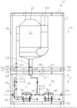
- FIG. 1 depicts schematically an exhaust gas scrubber system 10 configured for wet scrubbing of exhaust gas of a power plant in a marine vessel.
- the exhaust gas scrubber system 10 is particularly suitable for reducing sulphur oxide emissions of exhaust gas of an internal combustion piston engine e.g. when the engine is combusting fuel containing sulphur.
- the exhaust gas scrubber system is comprised of two or more modules 12, 14 which makes particularly the installation of the exhaust gas scrubber system into a marine vessel advantageous.
- the exhaust gas scrubber system 10 comprises a scrubber vessel module 14 and a scrubbing liquid processing module 12.
- the scrubbing liquid processing module 12 comprises a first support framework 18 which is configured to bear also support forces required to support the scrubber vessel module 14 on the first support framework 18 when these are installed in a marine vessel.
- the first support framework 18 is constructed mainly of slender steel beams generally into a form of rectangular prism.
- the first support framework 18 is used for holding process equipment necessary or desired for handling of the scrubber liquid.
- the scrubber liquid is based either on sea water or fresh water or a combination thereof, optionally added with chemicals suitable for desired emission reduction reactions.
- the scrubbing liquid processing module 12 comprises fluid connections by means of which the scrubbing liquid can be brought into and removed from the scrubber system 10.
- the scrubbing liquid processing module 12 comprises a clean scrubbing liquid outlet 20 through which clean scrubbing liquid is fed to the scrubbing vessel module 14.
- the scrubbing liquid processing module 12 comprises a used scrubbing liquid inlet 22 through which used scrubbing liquid can be received from the scrubber vessel module 14 to the scrubbing liquid processing module 12.
- the scrubbing liquid processing module 12 comprises also a used scrubbing liquid outlet 24 via which a main stream of the used scrubbing liquid can be transferred away from the scrubbing liquid processing module 12.
- the scrubbing liquid processing module 12 comprises a clean scrubbing liquid inlet 26 via which the clean scrubbing liquid can be brought into the scrubbing liquid processing module 12.
- the scrubber vessel module 14 comprises fluid connections by means of which the scrubbing liquid can transferred between the scrubber vessel module 14 and the scrubbing liquid processing module 12 of the scrubber system 10.
- the scrubber vessel module 14 comprises a second support framework 19.
- the second support framework 19 also is constructed mainly of slender steel beams into a form of rectangular prism.
- the scrubbing vessel module 14, comprises exhaust gas inlet 28 and outlet 30 by means of which the exhaust gas can be fed into the scrubbing vessel module 14 and removed from the module 14 to the surrounding air or to a further processing of the exhaust gas.
- the scrubber vessel module 14 comprises a clean scrubbing liquid inlet 32 through which clean scrubbing liquid is fed from the scrubbing liquid processing module 12 to the scrubbing vessel module 14.
- the scrubber vessel module 14 comprises a used scrubbing liquid outlet 34 through which used scrubbing liquid can be removed from the scrubber vessel module to the scrubbing liquid processing module 12.
- the scrubber vessel module 14 comprises as its main component a scrubber vessel 16.
- the exhaust gas inlet 28 and outlet 30 are connected to the scrubber vessel 16 for introducing and withdrawing the exhaust gas into and from the scrubber vessel 16.
- the scrubbing liquid processing module 12 comprises components for processing or handling the scrubbing liquid by means of which clean scrubbing liquid is can be introduced to the scrubber vessel and used scrubbing liquid can be received from the scrubber vessel.
- the clean scrubbing liquid is introduced from the scrubbing liquid processing module 12 to the scrubber vessel module 14 and the used scrubbing liquid is returned from the scrubber vessel module 14 to the scrubbing liquid processing module 12.
- the scrubber vessel 16 is configured to subject the exhaust gas to direct contact with a scrubbing liquid in the scrubber vessel 16 for cleaning the exhaust gas in a manner known as such in the art of exhaust gas scrubbers.
- Exhaust gas enters the scrubber vessel and is sprayed with seawater.
- the sulphur oxide in the exhaust reacts with water and forms sulphuric acid. Chemicals may not be required since the natural alkalinity of seawater neutralises the acid.
- the connecting inlets and outlets are aligned with each other such that they can be coupled with each other.
- the clean scrubbing liquid inlet 32 of the scrubber vessel module 14 and the clean scrubbing liquid outlet 20 of the scrubbing liquid processing module 12 are arranged in flow connection with each other for feeding the clean scrubbing liquid into the scrubber vessel, and the used scrubbing liquid outlet 34 of the scrubber vessel module 14 and the used scrubbing liquid inlet 22 of the scrubbing liquid processing module 12 are arranged in flow connection with each other for leading used scrubbing liquid from the scrubber vessel 16 to the scrubbing liquid processing module 12.
- the modules are prefabricated such that the laying of the scrubber vessel module 14 on the scrubbing liquid processing module 12 during the installation sets respective connecting part, such as flanges at right positions for easy coupling.
- the scrubbing liquid processing module 12 comprises an open loop scrubbing liquid processing equipment 36 and a closed loop scrubbing liquid processing equipment 38.
- the open loop means in practise that the exhaust gas scrubber system can be used in a once-through principal in respect to the scrubbing liquid, which is in this case the sea water. In the open loop operation the sea water is taken in, sprayed into the scrubber vessel 16 to treat the exhaust gas and eventually, after desired cleaning, discharged back to the sea.
- the closed loop means that the scrubber system has scrubbing liquid re-circulation system into which only make-up liquid and desired chemicals may be added to compensate an amount of scrubbing liquid removed from the circulation. In the closed loop system the scrubbing liquid may be based on the sea water, fresh water or a combination thereof.
- FIG 2 there is shown the scrubbing liquid processing module 12 of the figure 1 where the open loop scrubbing liquid processing equipment 36 is in operating state.
- the closed loop scrubbing liquid processing equipment 38 is in turn shown in non-operating state. The state is indicated such that a solid line means operating state and dash dot line means non-operating state.
- the open loop scrubbing liquid processing equipment 36 in the scrubbing liquid processing module 12 comprises substantially direct flow connection between the at least one clean scrubbing liquid inlet 26 and the at least one clean scrubbing liquid outlet 20.
- Direct flow connection means that there is no substantial accumulation space between said inlet 26 and outlet 20 so that the amount or rate of fluid entered into the scrubbing liquid inlet 26 corresponds to the amount or rate of fluid exited from the outlet 20.
- the open loop scrubbing liquid processing equipment 36 in the scrubbing liquid processing module 12 comprises flow connection between the at least one used scrubbing liquid inlet 22 and the at least one used scrubbing liquid outlet 24.
- a residence tank 40 arranged in flow communication between with the used scrubbing liquid inlet 22 and the used scrubbing liquid outlet 24 of the module 12.
- the residence tank is used for treating the used scrubbing liquid, comprising at least partial cleaning of the water, such that it can be eventually discharged to the water.
- the scrubbing liquid processing module 12 has a form of rectangular prism and it has a top face 12' through which flow communication between the scrubbing liquid processing module 12 and the scrubber vessel module 14 is arranged to take place, and correspondingly the scrubber vessel module 14 has a form of rectangular prism and it has a bottom face 14' through which flow communication between the scrubbing liquid processing module 12 and the scrubber vessel module 14 is arranged to take place.
- the flow communication comprises the clean scrubbing liquid pipe 20' and a used scrubbing liquid pipe 22'.
- the closed loop scrubbing liquid processing equipment 38 in the scrubbing liquid processing module 12 comprises a buffer tank 42.
- the buffer tank 42 is arranged in substantially direct flow connection with the at least one clean scrubbing liquid outlet 20 for feeding clean scrubbing liquid from the buffer tank 42 to the scrubber vessel 16 in the scrubbing vessel module 12.
- the buffer tank 42 is also arranged in substantially direct flow connection with the at least one used scrubbing liquid inlet 22 for receiving used scrubbing liquid from the scrubber vessel 16 to the buffer tank 42.
- the buffer tank 42 is used for removing impurities from the scrubbing liquid.
- the at least one clean scrubbing liquid outlet 20 and at least one used scrubbing liquid inlet 22 are common to the open loop scrubbing liquid processing equipment 36 and the closed loop scrubbing liquid processing equipment 38 in the scrubbing liquid processing module 12.
- the desired operational state is set by suitably opening or closing a valve 44.1 arranged to a piping between the clean scrubbing liquid outlet 20 and the clean scrubbing liquid inlet 26, a valve 44.2 arranged to a piping between the clean scrubbing liquid outlet 20 and the buffer tank 42, a valve 46.1 arranged to a piping between the used scrubbing liquid inlet 22 and the buffer tank 42 and a valve 46.2 arranged to a piping between the used scrubbing liquid inlet 22 and the residence tank 40.
- the clean scrubbing liquid inlet 26 is in flow connection with the buffer tank 42 for leading make-up liquid into the liquid circulation.
- the piping between the clean scrubbing liquid inlet 26 is in flow connection with the buffer tank 42 is provided with a valve 48 to control the flow of make-up liquid.
- the buffer tank 42 is provided with an outlet 50 for a discharge flow of scrubbing liquid effluent.
- Respectively the residence tank 40 is provided with an outlet 52 for a discharge flow of scrubbing liquid effluent.
- the scrubbing liquid processing module 12 comprises only the closed loop scrubbing liquid processing equipment 38 or only the closed loop scrubbing liquid processing equipment 36.
- the scrubbing liquid processing module 12 comprises both the closed loop scrubbing liquid processing equipment 38 and the closed loop scrubbing liquid processing equipment 36.
- the scrubbing liquid processing module 12 comprises only the closed loop scrubbing liquid processing equipment 38 or only the closed loop scrubbing liquid processing equipment 36, there is a space reservation for the omitted processing equipment in the scrubbing liquid processing module 12.
- the first support framework 18 is provided with a set of first connector parts 54 at its top part.
- the second support framework 19 is provided with a set of second connector parts 56 at its bottom part.
- the set of the first connector parts 54 are compatible with the set of the second connector parts 56 to lock the scrubber vessel module 14 onto the scrubbing liquid processing module 12 by releasable connection between the set of the first connector parts 54 and the set of the second connector parts 56.
- the connector parts between the modules provide easy coupling of the first support framework 18 to the second support framework 19 and simultaneous aligning the frameworks horizontally with each other for at least for speeding up the installation work.
- the connector parts 54, 56 can be utilized in mere aligning the second framework 19 onto the first framework 18 wherein the final mechanical attachment of the frameworks with each other is made by other suitable means, such as welding.
- the first support framework 18 and the second support framework 19 are provided with a set of connector parts at its corners, which are compatible with the international standard ISO 1161:1984 to attach the exhaust gas scrubber system to its compatible base in the marine vessel.
- the connector parts By means of the connector parts the first support framework 18 and the second support framework 19 can be connected with each other and to the container vessel in a straightforward manner.
- the exhaust gas scrubber system 10 according to the figure 1 assembled in a marine vessel 100. More particularly the scrubber system is on a main deck 102 of the vessel.
- the vessel is provided with an engine106 in its engine room 112 and an exhaust flue 108 into which the exhaust gas inlet 28 is connected.
- the engine can also be referred to as a power plant because the vessel is usually provided with several engines.
- the exhaust gas scrubber system 10 is assembled on the main deck 102 directly above the engine room 112. This way connecting a prefabricated exhaust gas scrubber can be connected to the sea water systems of the vessel and exhaust gas flue 108 in straightforward manner.
- the vessel is provided with a sea chest 114 i.e.
- a source of sea water which is fluidly connected to the clean scrubbing liquid inlet 26 of the scrubbing liquid processing module 12.
- Respectively the used scrubbing liquid outlet 24 is fluidly connected to a sea water discharge 116 via a sea water return conduit arranged to the vessel 100.
- the scrubber system 10 is particularly intended for use in a container ship which is configured to transport goods stored in intermodal containers 110, which can be stacked into the vessel as is shown in the figure 4 .
- An intermodal container is a large standardized shipping container, designed and built for intermodal freight transport, meaning these containers can be used across different modes of transport - from ship to rail to truck - without unloading and reloading their cargo.
- These containers are known under a number of names, such as simply container, cargo or freight container, ISO container, shipping, sea or ocean container, container van or (Conex) box, sea or c can. Fixing of container to its support can be assisted at least during the installation by making use of a special connector parts arranged at each one of the corners of a container.
- the connector part is defined in the international standard ISO 1161:2016.
- the scrubbing liquid processing module 12 and the scrubber vessel module 14 have an equal footprint area measured as the product of outermost length and width dimensions thereof. This way the utilization of the deck space on the main deck is as efficient as possible.
- the footprint area of the scrubbing liquid processing module 12 and the scrubber vessel module 12 is a multiple of a footprint area of an intermodal container according to the international standard ISO 668:2013, the utilization of a deck area in a container vessel is as efficient as possible. Because the exhaust gas scrubber system 10 occupy a space which is equivalent to one or more intermodal containers according to the international standard ISO 668:2013, the loss of cargo capacity is minimized when the exhaust gas scrubber system 10 is assembled on the main deck of the container vessel 100.
- the first support framework 18 is provided with a set of connector parts 60 which are compatible for connection to a set of connector parts 62 arranged to a base 104 in a marine vessel.
- the connector part 62 arranged to a base in the marine vessel for attaching an intermodal container can be utilized in attachment of the first support framework onto the vessel's main deck 102.
- the set of connector parts are advantageously compatible with the international standard ISO 1161:1984 to attach the exhaust gas scrubber system to its compatible base in the marine vessel.
- the exhaust gas scrubber system 10 is installed onto a main deck 102 of a marine vessel such that first is provided an exhaust gas scrubber system 10 comprising a scrubber vessel module 14 and a scrubbing liquid processing module 12. Next, the scrubbing liquid processing module 12 is lifted and attached on the deck of the marine vessel. Advantageously the position is selected so that the scrubbing liquid processing module 12 is directly above the machine room 112 of the vessel. After the scrubbing liquid processing module 12 has been attached on the deck, the scrubber vessel module 14 is laid on the scrubbing liquid processing module 12 and the modules are attached with each other. Next the scrubbing liquid processing module 12 can be fluidly connected to vessel accessory.
- the clean scrubbing liquid inlet 26 is connected to the source of sea water and the used scrubbing liquid outlet 24 is connected to the vessel's sea water discharge.
- electric power supply and control system is connected to the exhaust gas scrubber system 10.
- the scrubber vessel module 14 is fluidly connected to the scrubbing liquid processing module 12 and to a flue 108 of the vessel 100.
- Method of installing the exhaust gas scrubber system 10 to the main deck 102 is advantageously applied so that during the vessel is not underway, meaning that the vessel can be moored or docked, the scrubbing liquid processing module 12, which has been prefabricated to include at least the open loop scrubbing liquid processing equipment 36 into the first support framework 18, is hauled onto the vessel.
- the scrubbing liquid processing module 12 is then attached to the base 104 in the marine vessel 100. After the attaching the scrubbing liquid processing module 12 to the base 104, the vessel is departed and used normally underway. After using the vessel underway, the vessel is moored again in due course. Now, during the vessel is again not underway the scrubber vessel module 14 is hauled to the vessel 100, laid on the scrubbing liquid processing module 12, and attached to the scrubbing liquid processing module 12 and/or to the vessel 100.
- the scrubbing liquid processing module 12 after the scrubbing liquid processing module 12 has been attached to the vessel and only after the vessel has departed the scrubbing liquid processing module 12 is fluidly connected to the vessel while the vessel is underway. This shortens the single mooring time even more.
- the scrubber module 14 is fluidly connected to the vessel and to the scrubbing liquid processing module 12 only after the vessel has departed and the vessel is underway again. This shortens the single mooring time still more.
- Fluidly connecting the scrubber system 10 to the vessel's accessories comprises connecting an at least one clean scrubbing liquid inlet 26 of the scrubbing liquid processing module 12 to a source of sea water 114 in the vessel, and connecting at least one used scrubbing liquid outlet 24 of the scrubbing liquid processing module 12 to a sea water return conduit 116 in the vessel, and further connecting the scrubbing liquid processing module 12 to the scrubber module 14 comprises connecting the at least one clean scrubbing liquid outlet 20 of the scrubbing liquid processing module 12 to the scrubber module 14 and connecting the used scrubbing liquid inlet of the scrubbing liquid processing module 12 to the scrubber module 14, as well as connecting the exhaust gas inlet 28 to the flue 108 of the vessel 100.
- FIG. 5 depicts schematically an exhaust gas scrubber system 10 configured for wet scrubbing of exhaust gas of a power plant in a marine vessel according to an embodiment of the invention.
- the exhaust gas scrubber system is comprised of two or more modules 12, 14 which makes particularly the installation of the exhaust gas scrubber system into a marine vessel advantageous.
- the scrubber system shown in the figure 5 is substantially similar to that shown in the Figure 1 but in this embodiment the exhaust gas scrubber system 10 comprises two scrubber vessel module sections 14', 14" which form the scrubber vessel module 14. The section are laid one above the other. This way the scrubber vessel module 14 is comprised of several sections 14', 14".
- the embodiment of the Figure 5 is particularly advantageous for scrubbing exhaust gas having greater flow rate than in the embodiment shown in the Figure 1 since the scrubber unit 16 is comprised of two parts 16,16' which are supported by respective scrubber vessel module section 14',14".
- the first section 14' of the scrubber vessel module 14 comprises a lower part of the scrubber unit 16 and the second section 14" of the scrubber vessel module 14 comprises an upper part of the scrubber unit 16'.
- Scrubber unit 16,16' comprises a joint 15 by means of which the lower part of the scrubber unit 16 and the upper part of the scrubber unit 16' are joined with each other after the second section 14" of the scrubber vessel module 14 has been positioned above the first section 14' of the scrubber vessel module 14, according to the invention.
- the exhaust gas inlet 28 is provided a joint 27 by means of which the sections of the exhaust gas inlet 28 at first section 14' of the scrubber vessel module 14 and the second section 14" of the scrubber vessel module 14 are connectable with each other.
- the joints 15, 27 can be a welded or a flange joint.
- the clean scrubbing liquid pipe 20' is provided a releasable connection 32', such as a flange connection.
- the second support framework 19 is comprised of a first section of the second support framework 19' and a second section of the second support framework 16.
- the second support framework i.e. both sections thereof, is also constructed mainly of slender steel beams into a form of rectangular prism as in the embodiments shown in the Figure 1 .
- the scrubber system 10 in the Figure 5 comprises one scrubbing liquid processing module 12, which is practically similar to that shown in and described with the reference to the Figure 1 .
- the first support framework 18 of the processing module 12 is configured to bear the support forces required to support the first section 14' of the scrubber vessel module 14 and the second section 14" of the scrubber vessel module 14 on the first support framework 18 when these are installed in a marine vessel.
- the scrubbing liquid processing module 12 comprises an open loop scrubbing liquid processing equipment 36 and a closed loop scrubbing liquid processing equipment 38.
- the exhaust gas scrubber system 10 is installed onto a main deck of a marine vessel such that first is provided an exhaust gas scrubber system 10 comprising a first section 14" of the scrubber vessel module 14 and a second section 14" of the scrubber vessel module 14' and a scrubbing liquid processing module 12. Next, the scrubbing liquid processing module 12 is lifted and attached on the deck of the marine vessel 100.
- the position is selected so that the scrubbing liquid processing module 12 is directly above the machine room 112 of the vessel and/next to an engine casing 111 of the vessel 100.
- the first section 14' of the scrubber vessel module 14 is laid on the scrubbing liquid processing module 12 and the modules are attached with each other.
- the second section 14" of the scrubber vessel module 14 is laid on the first section of the scrubber vessel module 14 and the module sections 14', 14" are attached with each other.
- the first section 14' and the second section 14" also have a footprint area which is a multiple of a footprint area of any intermodal container according to the international standard ISO 668:2013.
- Method of installing the exhaust gas scrubber system 10 to the main deck 102 is advantageously applied so that during the vessel is not underway, meaning that the vessel can be moored or docked, one of the modules or module sections, which has been prefabricated, is hauled onto the vessel.
- the hauled module is then attached to the base 104 in the marine vessel 100 or to a module previously installed to the vessel 100. After properly attaching said one of modules or module sections onto the vessel, it is departed and used normally underway. After using the vessel underway, the vessel is moored again in due course.
- a second one of modules or module sections, which has been prefabricated, is hauled onto the vessel 100, laid on a module previously installed to the vessel 100 and attached thereto and/or to the vessel 100.
- the scrubbing liquid processing module 12 and the sections of the scrubber vessel module 14 are hauled to the vessel at different mooring occasions, one at a time, a single mooring time is not substantially lengthened due to installation of either one of the modules or the sections, and thus the disturbance of the installation of the exhaust gas scrubber system 10 to the cargo transport efficiency of the vessel is minimized.
Landscapes
- Engineering & Computer Science (AREA)
- Chemical & Material Sciences (AREA)
- Combustion & Propulsion (AREA)
- Chemical Kinetics & Catalysis (AREA)
- General Engineering & Computer Science (AREA)
- Mechanical Engineering (AREA)
- Health & Medical Sciences (AREA)
- Biomedical Technology (AREA)
- Environmental & Geological Engineering (AREA)
- Analytical Chemistry (AREA)
- General Chemical & Material Sciences (AREA)
- Oil, Petroleum & Natural Gas (AREA)
- Ocean & Marine Engineering (AREA)
- Treating Waste Gases (AREA)
- Gas Separation By Absorption (AREA)
- Exhaust Gas After Treatment (AREA)
Claims (15)
- Verfahren zum Installieren eines Abgaswäschersystems (10) eines Kraftwerks (106) in einem Seeschiff (100), wobei das Verfahren umfasst:Bereitstellen eines Abgaswäschersystems (10), das ein Wäscherbehältermodul (14) und ein Waschflüssigkeitsverarbeitungsmodul (12) umfasst,Fließverbinden des Waschflüssigkeitsverarbeitungsmoduls (12) mit Zubehör des Seeschiffes,Fließverbinden des Wäscherbehältermoduls (14) mit dem Waschflüssigkeitsverarbeitungsmodul (12) und mit einem Rauchabzug des Seeschiffes,Befestigen des Waschflüssigkeitsverarbeitungsmoduls (12) auf einem Deck des Seeschiffes (100),gekennzeichnet durchBefestigen des Waschflüssigkeitsverarbeitungsmoduls (12) auf einem Deck des Seeschiffes (100) über eine erste Tragrahmenkonstruktion (18) des Waschflüssigkeitsverarbeitungsmoduls (12),Auflegen des Wäscherbehältermoduls (14) auf die erste Tragrahmenkonstruktion (18) des Waschflüssigkeitsverarbeitungsmoduls (12) mithilfe einer zweiten Tragrahmenkonstruktion (19) und Befestigen der Module (12, 14) aneinander, so dass die zweite Tragrahmenkonstruktion (19) von der ersten Tragrahmenkonstruktion (18) getragen wird, wobei die erste Tragrahmenkonstruktion (18) dazu ausgestaltet ist, Tragkräfte auszuhalten, die erforderlich sind, um das Wäscherbehältermodul (14) auf der ersten Tragrahmenkonstruktion (18) zu tragen, und die erste Tragrahmenkonstruktion (18) an ihrem oberen Teil mit einem Satz erster Verbindungsstücke (54) versehen ist und die zweite Tragrahmenkonstruktion (19) an ihrem unteren Teil mit einem Satz zweiter Verbindungsstücke (56) versehen ist und der Satz der ersten Verbindungsstücke (54) mit dem Satz der zweiten Verbindungsstücke (56) kompatibel ist, um das Wäscherbehältermodul (14) über eine lösbare Verbindung zwischen dem Satz der ersten Verbindungsstücke (54) und dem Satz der zweiten Verbindungsstücke (56) auf dem Waschflüssigkeitsverarbeitungsmodul (12) zu arretieren.
- Verfahren zum Installieren eines Abgaswäschersystems (10) an einem Kraftwerk (106) in einem Seeschiff (100) nach Anspruch 1, gekennzeichnet durch Befestigen des Waschflüssigkeitsverarbeitungsmoduls (12) über eine Tragrahmenkonstruktion an einer Basis des Seeschiffes (100) mithilfe von Verbindungsstücken, die an der Tragrahmenkonstruktion angeordnet sind, und mithilfe von Verbindungsgegenstücken, die an der Basis des Seeschiffes angeordnet sind, wobei die Verbindungsgegenstücke mit den Verbindungsstücken, die an der Tragrahmenkonstruktion angeordnet sind, kompatibel sind.
- Verfahren zum Installieren eines Abgaswäschersystems (10) eines Kraftwerks (106) in einem Seeschiff (100) nach Anspruch 1, gekennzeichnet durch Befestigen des Waschflüssigkeitsverarbeitungsmoduls (12) auf einem Hauptdeck des Seeschiffes (100).
- Verfahren zum Installieren eines Abgaswäschersystems (10) eines Kraftwerks (106) in einem Seeschiff (100) nach Anspruch 2, gekennzeichnet durch Befestigen des Waschflüssigkeitsverarbeitungsmoduls (12) über eine Tragrahmenkonstruktion an einer Basis in dem Seeschiff (100) mithilfe von Verbindungsstücken, die kompatibel mit der internationalen Norm ISO 1161:1984 hergestellt und an der Tragrahmenkonstruktion angeordnet sind, und mithilfe von Verbindungsgegenstücken, die kompatibel mit der internationalen Norm ISO 1161:1984 hergestellt und an der Basis des Seeschiffes angeordnet sind.
- Verfahren zum Installieren eines Abgaswäschersystems (10) eines Kraftwerks (106) in einem Seeschiff (100) nach Anspruch 1, gekennzeichnet durch(a) während das Seeschiff nicht unterwegs ist Befördern des Waschflüssigkeitsverarbeitungsmoduls (12) auf das Seeschiff und Befestigen des Waschflüssigkeitsverarbeitungsmoduls (12) an der Basis in dem Seeschiff (100);(b) Benutzen des Seeschiffes unterwegs nach Schritt (a),(c) Vertäuen des Seeschiffes nach Schritt (b) und während das Seeschiff nicht unterwegs ist Befördern des Wäscherbehältermoduls (14) auf das Seeschiff und Auflegen des Wäscherbehältermoduls (14) auf das Waschflüssigkeitsverarbeitungsmodul (12) und Befestigen des Wäschermoduls an dem Waschflüssigkeitsverarbeitungsmodul (12) und/oder dem Seeschiff.
- Verfahren zum Installieren eines Abgaswäschersystems (10) eines Kraftwerks (106) in einem Seeschiff (100) nach Anspruch 1, gekennzeichnet durch(a) während das Seeschiff nicht unterwegs ist Befördern des Waschflüssigkeitsverarbeitungsmoduls (12) auf das Seeschiff und Befestigen des Waschflüssigkeitsverarbeitungsmoduls (12) an der Basis in dem Seeschiff (100);(b) während das Seeschiff unterwegs ist Fließverbinden des Waschflüssigkeitsverarbeitungsmoduls (12) mit dem Zubehör des Seeschiffes;(c) während das Seeschiff nicht unterwegs ist Befördern des Wäscherbehältermoduls (14) auf das Seeschiff und Auflegen des Wäscherbehältermoduls (14) auf das Waschflüssigkeitsverarbeitungsmodul (12) und Befestigen des Wäschermoduls an dem Waschflüssigkeitsverarbeitungsmodul (12);(d) während das Seeschiff unterwegs ist Fließverbinden des Wäschermoduls mit dem Waschflüssigkeitsverarbeitungsmodul (12) und mit dem Rauchabzug des Seeschiffes;wobei die Schritte in der Reihenfolge (a)-(b)-(c)-(d) ausgeführt werden.
- Verfahren zum Installieren eines Abgaswäschersystems (10) eines Kraftwerks (106) in einem Seeschiff (100) nach Anspruch 1, gekennzeichnet dadurch, dass
das Fließverbinden des Waschflüssigkeitsverarbeitungsmoduls (12) mit dem Zubehör des Seeschiffes ein Verbinden wenigstens eines Einlasses für reine Waschflüssigkeit (26) des Waschflüssigkeitsverarbeitungsmoduls (12) mit einer Seewasserquelle in dem Seeschiff und ein Verbinden wenigstens eines Auslasses für benutzte Waschflüssigkeit (24) des Waschflüssigkeitsverarbeitungsmoduls (12) mit einer Seewasserrückführleitung in dem Seeschiff umfasst und das Verbinden des Waschflüssigkeitsverarbeitungsmoduls (12) mit dem Wäschermodul ein Verbinden wenigstens eines Auslasses für reine Waschflüssigkeit (20) des Waschflüssigkeitsverarbeitungsmoduls (12) umfasst. - Abgaswäschersystem (10) zum Nasswaschen von Abgas eines Kraftwerks (106) in einem Seeschiff (100), wobei das Abgaswäschersystem (10) umfasst:ein Waschflüssigkeitsverarbeitungsmodul (12), das dazu ausgestaltet ist, Waschflüssigkeit von einem Wäscherbehälter (16) zu empfangen und dem Wäscherbehälter (16) Waschflüssigkeit zuzuführen,ein Wäscherbehältermodul (14), das einen Wäscherbehälter (16) umfasst, der dazu ausgestaltet ist, das Abgas in dem Wäscherbehälter (16) einem direkten Kontakt mit einer Waschflüssigkeit zu unterziehen, dadurch gekennzeichnet, dassdas Waschflüssigkeitsverarbeitungsmodul (12) eine erste Tragrahmenkonstruktion (18) umfasst und das Wäscherbehältermodul (14) eine zweite Tragrahmenkonstruktion (19) umfasst und das Wäscherbehältermodul (14) derart auf dem Waschflüssigkeitsverarbeitungsmodul (12) befestigt ist, dass die zweite Tragrahmenkonstruktion (19) von der ersten Tragrahmenkonstruktion (18) getragen wird, und dass die erste Tragrahmenkonstruktion (18) an ihrem oberen Teil mit einem Satz erster Verbindungsstücke (54) versehen ist und die zweite Tragrahmenkonstruktion (19) an ihrem unteren Teil mit einem Satz zweiter Verbindungsstücke (56) versehen ist und dass der Satz der ersten Verbindungsstücke (54) mit dem Satz der zweiten Verbindungsstücke (56) kompatibel ist, um das Wäscherbehältermodul (14) über eine lösbare Verbindung zwischen dem Satz der ersten Verbindungsstücke (54) und dem Satz der zweiten Verbindungsstücke (56) auf dem Waschflüssigkeitsverarbeitungsmodul (12) zu arretieren.
- Abgaswäschersystem (10) nach Anspruch 8, dadurch gekennzeichnet, dass das Waschflüssigkeitsverarbeitungsmodul (12) wenigstens einen Abgaseinlass (28), wenigstens einen Abgasauslass (30), wenigstens einen Einlass für reine Waschflüssigkeit (32) und wenigstens einen Auslass für benutzte Waschflüssigkeit (34) umfasst und mit einem Wäscherbehälter (16) fließverbunden ist und dass
das Waschflüssigkeitsverarbeitungsmodul (12) wenigstens einen Auslass für reine Waschflüssigkeit (20), wenigstens einen Einlass für benutzte Waschflüssigkeit (22), wenigstens einen Auslass für benutzte Waschflüssigkeit (24), wenigstens einen Einlass für reine Waschflüssigkeit (26) und eine Waschflüssigkeitsverarbeitungseinrichtung (36, 38) umfasst,
und dass der wenigstens eine Einlass für reine Waschflüssigkeit (32) des Wäscherbehältermoduls (14) und der wenigstens eine Auslass für reine Waschflüssigkeit (26) des Waschflüssigkeitsverarbeitungsmoduls (12) zwecks Zuführens der reinen Waschflüssigkeit in den Wäscherbehälter (16) in Fließverbindung miteinander stehen,
und dass der wenigstens eine Auslass für benutzte Waschflüssigkeit (34) des Wäscherbehältermoduls (14) und der wenigstens eine Einlass für benutzte Waschflüssigkeit (22) des Waschflüssigkeitsverarbeitungsmoduls (12) zwecks Leitens benutzter Waschflüssigkeit von dem Wäscherbehälter (16) zu dem Waschflüssigkeitsverarbeitungsmodul (12) in Fließverbindung miteinander stehen. - Abgaswäschersystem (10) nach Anspruch 9, dadurch gekennzeichnet, dass das Waschflüssigkeitsverarbeitungsmodul (12) eine Waschflüssigkeitsverarbeitungseinrichtung (36) mit offenem Regelkreis umfasst, die eine direkte Fließverbindung zwischen dem wenigstens einen Einlass für reine Waschflüssigkeit (26) und dem wenigstens einen Auslass für reine Waschflüssigkeit (20) umfasst, und dass das Waschflüssigkeitsverarbeitungsmodul (12) einen Verweiltank (40) umfasst, der in Fließverbindung mit dem wenigstens einen Einlass für benutzte Waschflüssigkeit (22) und dem wenigstens einen Auslass für benutzte Waschflüssigkeit (24) steht.
- Abgaswäschersystem (10) nach Anspruch 9, dadurch gekennzeichnet, dass das Waschflüssigkeitsverarbeitungsmodul (12) eine Waschflüssigkeitsverarbeitungseinrichtung (38) mit geschlossenem Regelkreis umfasst, die einen Puffertank (42) und eine direkte Fließverbindung zwischen dem wenigstens einen Einlass für benutzte Waschflüssigkeit (22) und dem Puffertank (42) und eine direkte Fließverbindung zwischen dem Puffertank (42) und dem wenigstens einen Auslass für reine Waschflüssigkeit (20) umfasst.
- Abgaswäschersystem (10) zum Nasswaschen von Abgas eines Kraftwerks (106) in einem Seeschiff (100) nach Anspruch 9, dadurch gekennzeichnet, dass die erste Tragrahmenkonstruktion (18) mit einem Satz von Verbindungsstücken versehen ist, die zur Verbindung mit einem Satz von Verbindungsstücken, die an einer Basis in einem Seeschiff (100) angeordnet sind, kompatibel sind.
- Abgaswäschersystem (10) zum Nasswaschen von Abgas eines Kraftwerks (106) in einem Seeschiff (100) nach Anspruch 12, dadurch gekennzeichnet, dass der Satz von Verbindungsstücken mit der internationalen Norm ISO 1161:1984 kompatibel ist, um das Abgaswäschersystem (10) an seiner kompatiblen Basis in dem Seeschiff (100) zu befestigen.
- Abgaswäschersystem (10) nach Anspruch 8, dadurch gekennzeichnet, dass das Waschflüssigkeitsverarbeitungsmodul (12) und das Wäscherbehältermodul (14) eine gleiche Grundfläche aufweisen, gemessen als das Produkt der äußersten Längen- und Breitenabmessungen derselben.
- Abgaswäschersystems (10) nach Anspruch 8, dadurch gekennzeichnet, dass das Waschflüssigkeitsverarbeitungsmodul (12) und das Wäscherbehältermodul (14) eine Grundfläche, gemessen als das Produkt der äußersten Längen- und Breitenabmessungen derselben, aufweisen, die ein Vielfaches einer Grundfläche eines beliebigen Intermodal-Containers gemäß der internationalen Norm ISO 668:2013 ist.
Applications Claiming Priority (1)
| Application Number | Priority Date | Filing Date | Title |
|---|---|---|---|
| PCT/EP2017/079841 WO2019101286A1 (en) | 2017-11-21 | 2017-11-21 | A method of installing an exhaust gas scrubber system of a power plant in a marine vessel and an exhaust gas scrubber system for wet scrubbing of exhaust gas of a power plant in a marine vessel |
Publications (2)
| Publication Number | Publication Date |
|---|---|
| EP3713656A1 EP3713656A1 (de) | 2020-09-30 |
| EP3713656B1 true EP3713656B1 (de) | 2021-07-21 |
Family
ID=60413205
Family Applications (1)
| Application Number | Title | Priority Date | Filing Date |
|---|---|---|---|
| EP17801453.6A Active EP3713656B1 (de) | 2017-11-21 | 2017-11-21 | Verfahren zum installieren eines abgasreinigungssystems einer kraftwerksanlage in einem wasserfahrzeug und abgasreinigungssystem zur nasswäsche von abgas einer kraftwerksanlage in einem wasserfahrzeug |
Country Status (4)
| Country | Link |
|---|---|
| EP (1) | EP3713656B1 (de) |
| KR (1) | KR102395685B1 (de) |
| CN (1) | CN111526934B (de) |
| WO (1) | WO2019101286A1 (de) |
Families Citing this family (4)
| Publication number | Priority date | Publication date | Assignee | Title |
|---|---|---|---|---|
| CN110318850B (zh) * | 2019-06-05 | 2021-07-16 | 广州文冲船厂有限责任公司 | 一种用于scr系统中的尿素循环系统 |
| JP7039790B2 (ja) * | 2019-08-02 | 2022-03-23 | 株式会社三井E&Sマシナリー | 排ガス処理装置およびその制御方法 |
| CN116635130A (zh) * | 2020-10-30 | 2023-08-22 | 马斯克公司 | 洗涤器出口组件 |
| EP4237670B1 (de) * | 2020-10-30 | 2026-02-18 | Maersk A/S | Wäscherauslassanordnung |
Family Cites Families (12)
| Publication number | Priority date | Publication date | Assignee | Title |
|---|---|---|---|---|
| DE19530362C1 (de) * | 1995-08-18 | 1996-10-31 | Thyssen Nordseewerke Gmbh | Vorrichtung zur Abgas- und Abluftführung auf Schiffen |
| DE102009006198B4 (de) * | 2009-01-26 | 2025-06-12 | airtainer GmbH & Co. KG | Vorrichtung zur großtechnischen Medienkonditionierung |
| FI124749B (fi) * | 2011-02-23 | 2015-01-15 | Wärtsilä Finland Oy | Pesurisysteemi pakokaasujen käsittelemiseksi vesialuksessa ja menetelmä pakokaasujen käsittelemiseksi vesialuksen pesurisysteemisessä |
| GB201103349D0 (en) * | 2011-02-28 | 2011-04-13 | Oceanox Ltd | Exhaust scrubbing |
| US8561395B2 (en) * | 2011-03-03 | 2013-10-22 | Tenneco Automotive Operating Company Inc. | Poka-yoke mounting system for an exhaust treatment device |
| KR101722232B1 (ko) * | 2011-05-19 | 2017-04-03 | 현대중공업 주식회사 | 선박 엔진의 배기가스 정화장치 |
| KR101424577B1 (ko) * | 2012-11-27 | 2014-08-01 | 주식회사 파나시아 | 분리형 반응기 및 그 조립방법 |
| US9057316B2 (en) * | 2012-12-03 | 2015-06-16 | Tenneco Automotive Operating Company Inc. | Exhaust component mounting structure |
| WO2014118819A1 (ja) * | 2013-01-30 | 2014-08-07 | 富士電機株式会社 | 舶用ディーゼルエンジン排ガス処理システム |
| CN104689699B (zh) * | 2015-02-16 | 2016-11-23 | 哈尔滨工程大学 | 一种船舶动力装置废气洗涤系统 |
| EP3085911B1 (de) * | 2015-04-22 | 2017-12-13 | Wärtsilä Moss AS | Wäscher mit doppeltem wassersystem |
| JP6442428B2 (ja) * | 2016-03-29 | 2018-12-19 | ヤンマー株式会社 | 船舶用の排気ガス浄化装置 |
-
2017
- 2017-11-21 EP EP17801453.6A patent/EP3713656B1/de active Active
- 2017-11-21 CN CN201780097126.7A patent/CN111526934B/zh active Active
- 2017-11-21 WO PCT/EP2017/079841 patent/WO2019101286A1/en not_active Ceased
- 2017-11-21 KR KR1020207016983A patent/KR102395685B1/ko active Active
Also Published As
| Publication number | Publication date |
|---|---|
| EP3713656A1 (de) | 2020-09-30 |
| KR102395685B1 (ko) | 2022-05-06 |
| CN111526934A (zh) | 2020-08-11 |
| CN111526934B (zh) | 2022-02-18 |
| KR20200087810A (ko) | 2020-07-21 |
| WO2019101286A1 (en) | 2019-05-31 |
Similar Documents
| Publication | Publication Date | Title |
|---|---|---|
| US11649030B2 (en) | Method and process for capturing carbon dioxide from marine engines | |
| EP3713656B1 (de) | Verfahren zum installieren eines abgasreinigungssystems einer kraftwerksanlage in einem wasserfahrzeug und abgasreinigungssystem zur nasswäsche von abgas einer kraftwerksanlage in einem wasserfahrzeug | |
| KR20180131548A (ko) | 선박용 탈황 장치, 선각 일체형 탈황 장치, 선박 및 선각 일체형 탈황 장치의 선박에 대한 설치 방법 | |
| FI124749B (fi) | Pesurisysteemi pakokaasujen käsittelemiseksi vesialuksessa ja menetelmä pakokaasujen käsittelemiseksi vesialuksen pesurisysteemisessä | |
| EP3362167A1 (de) | Auspuffgasreinigersystem für mehrere quellen | |
| WO2016140169A1 (ja) | 船舶の機関室構造 | |
| KR102439124B1 (ko) | 요소수탱크용 온도조절시스템 | |
| KR102543385B1 (ko) | Vlcc의 온실가스 배출 저감장치 및 동 장치를 구비한 vlcc | |
| KR102883964B1 (ko) | 선박의 요소수 생산 시스템 | |
| KR102740605B1 (ko) | 선박 | |
| KR102723649B1 (ko) | 탄소 포집 시스템 | |
| KR102723644B1 (ko) | 탄소 포집 시스템 | |
| CN218047282U (zh) | 一种船舶除硫改造系统 | |
| KR102920651B1 (ko) | 선박 | |
| KR20180104966A (ko) | 통합 배기가스 스크러빙 시스템, 그 통합 배기가스 스크러빙 시스템의 운전방법, 및 통합 배기가스 스크러빙 방법 | |
| KR20260062807A (ko) | 연료 처리 시스템 및 이를 포함하는 선박 | |
| CN118457888A (zh) | 一种大型集装箱船发电机废气进洗涤塔的集管布置方法 | |
| KR20100138353A (ko) | 케미컬 탱커에서의 카고 탱크 벤팅 시스템 |
Legal Events
| Date | Code | Title | Description |
|---|---|---|---|
| STAA | Information on the status of an ep patent application or granted ep patent |
Free format text: STATUS: UNKNOWN |
|
| STAA | Information on the status of an ep patent application or granted ep patent |
Free format text: STATUS: THE INTERNATIONAL PUBLICATION HAS BEEN MADE |
|
| PUAI | Public reference made under article 153(3) epc to a published international application that has entered the european phase |
Free format text: ORIGINAL CODE: 0009012 |
|
| STAA | Information on the status of an ep patent application or granted ep patent |
Free format text: STATUS: REQUEST FOR EXAMINATION WAS MADE |
|
| 17P | Request for examination filed |
Effective date: 20200512 |
|
| AK | Designated contracting states |
Kind code of ref document: A1 Designated state(s): AL AT BE BG CH CY CZ DE DK EE ES FI FR GB GR HR HU IE IS IT LI LT LU LV MC MK MT NL NO PL PT RO RS SE SI SK SM TR |
|
| AX | Request for extension of the european patent |
Extension state: BA ME |
|
| DAV | Request for validation of the european patent (deleted) | ||
| DAX | Request for extension of the european patent (deleted) | ||
| REG | Reference to a national code |
Ref country code: DE Ref legal event code: R079 Ref document number: 602017042585 Country of ref document: DE Free format text: PREVIOUS MAIN CLASS: B01D0047060000 Ipc: B01D0053500000 |
|
| GRAP | Despatch of communication of intention to grant a patent |
Free format text: ORIGINAL CODE: EPIDOSNIGR1 |
|
| STAA | Information on the status of an ep patent application or granted ep patent |
Free format text: STATUS: GRANT OF PATENT IS INTENDED |
|
| RIC1 | Information provided on ipc code assigned before grant |
Ipc: B01D 53/50 20060101AFI20210316BHEP Ipc: B01D 53/92 20060101ALI20210316BHEP Ipc: F01N 13/00 20100101ALI20210316BHEP Ipc: F01N 3/02 20060101ALI20210316BHEP Ipc: B01D 47/06 20060101ALI20210316BHEP |
|
| INTG | Intention to grant announced |
Effective date: 20210331 |
|
| GRAS | Grant fee paid |
Free format text: ORIGINAL CODE: EPIDOSNIGR3 |
|
| GRAA | (expected) grant |
Free format text: ORIGINAL CODE: 0009210 |
|
| STAA | Information on the status of an ep patent application or granted ep patent |
Free format text: STATUS: THE PATENT HAS BEEN GRANTED |
|
| AK | Designated contracting states |
Kind code of ref document: B1 Designated state(s): AL AT BE BG CH CY CZ DE DK EE ES FI FR GB GR HR HU IE IS IT LI LT LU LV MC MK MT NL NO PL PT RO RS SE SI SK SM TR |
|
| REG | Reference to a national code |
Ref country code: GB Ref legal event code: FG4D |
|
| REG | Reference to a national code |
Ref country code: CH Ref legal event code: EP |
|
| REG | Reference to a national code |
Ref country code: DE Ref legal event code: R096 Ref document number: 602017042585 Country of ref document: DE |
|
| REG | Reference to a national code |
Ref country code: AT Ref legal event code: REF Ref document number: 1412071 Country of ref document: AT Kind code of ref document: T Effective date: 20210815 |
|
| REG | Reference to a national code |
Ref country code: IE Ref legal event code: FG4D |
|
| REG | Reference to a national code |
Ref country code: LT Ref legal event code: MG9D |
|
| REG | Reference to a national code |
Ref country code: NL Ref legal event code: MP Effective date: 20210721 |
|
| REG | Reference to a national code |
Ref country code: AT Ref legal event code: MK05 Ref document number: 1412071 Country of ref document: AT Kind code of ref document: T Effective date: 20210721 |
|
| PG25 | Lapsed in a contracting state [announced via postgrant information from national office to epo] |
Ref country code: AT Free format text: LAPSE BECAUSE OF FAILURE TO SUBMIT A TRANSLATION OF THE DESCRIPTION OR TO PAY THE FEE WITHIN THE PRESCRIBED TIME-LIMIT Effective date: 20210721 Ref country code: BG Free format text: LAPSE BECAUSE OF FAILURE TO SUBMIT A TRANSLATION OF THE DESCRIPTION OR TO PAY THE FEE WITHIN THE PRESCRIBED TIME-LIMIT Effective date: 20211021 Ref country code: LT Free format text: LAPSE BECAUSE OF FAILURE TO SUBMIT A TRANSLATION OF THE DESCRIPTION OR TO PAY THE FEE WITHIN THE PRESCRIBED TIME-LIMIT Effective date: 20210721 Ref country code: NO Free format text: LAPSE BECAUSE OF FAILURE TO SUBMIT A TRANSLATION OF THE DESCRIPTION OR TO PAY THE FEE WITHIN THE PRESCRIBED TIME-LIMIT Effective date: 20211021 Ref country code: PT Free format text: LAPSE BECAUSE OF FAILURE TO SUBMIT A TRANSLATION OF THE DESCRIPTION OR TO PAY THE FEE WITHIN THE PRESCRIBED TIME-LIMIT Effective date: 20211122 Ref country code: NL Free format text: LAPSE BECAUSE OF FAILURE TO SUBMIT A TRANSLATION OF THE DESCRIPTION OR TO PAY THE FEE WITHIN THE PRESCRIBED TIME-LIMIT Effective date: 20210721 Ref country code: SE Free format text: LAPSE BECAUSE OF FAILURE TO SUBMIT A TRANSLATION OF THE DESCRIPTION OR TO PAY THE FEE WITHIN THE PRESCRIBED TIME-LIMIT Effective date: 20210721 Ref country code: RS Free format text: LAPSE BECAUSE OF FAILURE TO SUBMIT A TRANSLATION OF THE DESCRIPTION OR TO PAY THE FEE WITHIN THE PRESCRIBED TIME-LIMIT Effective date: 20210721 Ref country code: FI Free format text: LAPSE BECAUSE OF FAILURE TO SUBMIT A TRANSLATION OF THE DESCRIPTION OR TO PAY THE FEE WITHIN THE PRESCRIBED TIME-LIMIT Effective date: 20210721 Ref country code: ES Free format text: LAPSE BECAUSE OF FAILURE TO SUBMIT A TRANSLATION OF THE DESCRIPTION OR TO PAY THE FEE WITHIN THE PRESCRIBED TIME-LIMIT Effective date: 20210721 Ref country code: HR Free format text: LAPSE BECAUSE OF FAILURE TO SUBMIT A TRANSLATION OF THE DESCRIPTION OR TO PAY THE FEE WITHIN THE PRESCRIBED TIME-LIMIT Effective date: 20210721 |
|
| PG25 | Lapsed in a contracting state [announced via postgrant information from national office to epo] |
Ref country code: PL Free format text: LAPSE BECAUSE OF FAILURE TO SUBMIT A TRANSLATION OF THE DESCRIPTION OR TO PAY THE FEE WITHIN THE PRESCRIBED TIME-LIMIT Effective date: 20210721 Ref country code: LV Free format text: LAPSE BECAUSE OF FAILURE TO SUBMIT A TRANSLATION OF THE DESCRIPTION OR TO PAY THE FEE WITHIN THE PRESCRIBED TIME-LIMIT Effective date: 20210721 Ref country code: GR Free format text: LAPSE BECAUSE OF FAILURE TO SUBMIT A TRANSLATION OF THE DESCRIPTION OR TO PAY THE FEE WITHIN THE PRESCRIBED TIME-LIMIT Effective date: 20211022 |
|
| REG | Reference to a national code |
Ref country code: DE Ref legal event code: R097 Ref document number: 602017042585 Country of ref document: DE |
|
| PG25 | Lapsed in a contracting state [announced via postgrant information from national office to epo] |
Ref country code: DK Free format text: LAPSE BECAUSE OF FAILURE TO SUBMIT A TRANSLATION OF THE DESCRIPTION OR TO PAY THE FEE WITHIN THE PRESCRIBED TIME-LIMIT Effective date: 20210721 |
|
| PLBE | No opposition filed within time limit |
Free format text: ORIGINAL CODE: 0009261 |
|
| STAA | Information on the status of an ep patent application or granted ep patent |
Free format text: STATUS: NO OPPOSITION FILED WITHIN TIME LIMIT |
|
| PG25 | Lapsed in a contracting state [announced via postgrant information from national office to epo] |
Ref country code: SM Free format text: LAPSE BECAUSE OF FAILURE TO SUBMIT A TRANSLATION OF THE DESCRIPTION OR TO PAY THE FEE WITHIN THE PRESCRIBED TIME-LIMIT Effective date: 20210721 Ref country code: SK Free format text: LAPSE BECAUSE OF FAILURE TO SUBMIT A TRANSLATION OF THE DESCRIPTION OR TO PAY THE FEE WITHIN THE PRESCRIBED TIME-LIMIT Effective date: 20210721 Ref country code: RO Free format text: LAPSE BECAUSE OF FAILURE TO SUBMIT A TRANSLATION OF THE DESCRIPTION OR TO PAY THE FEE WITHIN THE PRESCRIBED TIME-LIMIT Effective date: 20210721 Ref country code: EE Free format text: LAPSE BECAUSE OF FAILURE TO SUBMIT A TRANSLATION OF THE DESCRIPTION OR TO PAY THE FEE WITHIN THE PRESCRIBED TIME-LIMIT Effective date: 20210721 Ref country code: CZ Free format text: LAPSE BECAUSE OF FAILURE TO SUBMIT A TRANSLATION OF THE DESCRIPTION OR TO PAY THE FEE WITHIN THE PRESCRIBED TIME-LIMIT Effective date: 20210721 Ref country code: AL Free format text: LAPSE BECAUSE OF FAILURE TO SUBMIT A TRANSLATION OF THE DESCRIPTION OR TO PAY THE FEE WITHIN THE PRESCRIBED TIME-LIMIT Effective date: 20210721 |
|
| 26N | No opposition filed |
Effective date: 20220422 |
|
| PG25 | Lapsed in a contracting state [announced via postgrant information from national office to epo] |
Ref country code: MC Free format text: LAPSE BECAUSE OF FAILURE TO SUBMIT A TRANSLATION OF THE DESCRIPTION OR TO PAY THE FEE WITHIN THE PRESCRIBED TIME-LIMIT Effective date: 20210721 |
|
| REG | Reference to a national code |
Ref country code: CH Ref legal event code: PL |
|
| PG25 | Lapsed in a contracting state [announced via postgrant information from national office to epo] |
Ref country code: LU Free format text: LAPSE BECAUSE OF NON-PAYMENT OF DUE FEES Effective date: 20211121 Ref country code: IT Free format text: LAPSE BECAUSE OF FAILURE TO SUBMIT A TRANSLATION OF THE DESCRIPTION OR TO PAY THE FEE WITHIN THE PRESCRIBED TIME-LIMIT Effective date: 20210721 Ref country code: BE Free format text: LAPSE BECAUSE OF NON-PAYMENT OF DUE FEES Effective date: 20211130 |
|
| REG | Reference to a national code |
Ref country code: BE Ref legal event code: MM Effective date: 20211130 |
|
| PG25 | Lapsed in a contracting state [announced via postgrant information from national office to epo] |
Ref country code: IE Free format text: LAPSE BECAUSE OF NON-PAYMENT OF DUE FEES Effective date: 20211121 |
|
| PG25 | Lapsed in a contracting state [announced via postgrant information from national office to epo] |
Ref country code: CY Free format text: LAPSE BECAUSE OF FAILURE TO SUBMIT A TRANSLATION OF THE DESCRIPTION OR TO PAY THE FEE WITHIN THE PRESCRIBED TIME-LIMIT Effective date: 20210721 |
|
| PG25 | Lapsed in a contracting state [announced via postgrant information from national office to epo] |
Ref country code: LI Free format text: LAPSE BECAUSE OF NON-PAYMENT OF DUE FEES Effective date: 20220701 Ref country code: HU Free format text: LAPSE BECAUSE OF FAILURE TO SUBMIT A TRANSLATION OF THE DESCRIPTION OR TO PAY THE FEE WITHIN THE PRESCRIBED TIME-LIMIT; INVALID AB INITIO Effective date: 20171121 Ref country code: CH Free format text: LAPSE BECAUSE OF NON-PAYMENT OF DUE FEES Effective date: 20220701 |
|
| PG25 | Lapsed in a contracting state [announced via postgrant information from national office to epo] |
Ref country code: MK Free format text: LAPSE BECAUSE OF FAILURE TO SUBMIT A TRANSLATION OF THE DESCRIPTION OR TO PAY THE FEE WITHIN THE PRESCRIBED TIME-LIMIT Effective date: 20210721 |
|
| PG25 | Lapsed in a contracting state [announced via postgrant information from national office to epo] |
Ref country code: TR Free format text: LAPSE BECAUSE OF FAILURE TO SUBMIT A TRANSLATION OF THE DESCRIPTION OR TO PAY THE FEE WITHIN THE PRESCRIBED TIME-LIMIT Effective date: 20210721 |
|
| PG25 | Lapsed in a contracting state [announced via postgrant information from national office to epo] |
Ref country code: MT Free format text: LAPSE BECAUSE OF FAILURE TO SUBMIT A TRANSLATION OF THE DESCRIPTION OR TO PAY THE FEE WITHIN THE PRESCRIBED TIME-LIMIT Effective date: 20210721 |
|
| PGFP | Annual fee paid to national office [announced via postgrant information from national office to epo] |
Ref country code: DE Payment date: 20251119 Year of fee payment: 9 |
|
| PGFP | Annual fee paid to national office [announced via postgrant information from national office to epo] |
Ref country code: GB Payment date: 20251121 Year of fee payment: 9 |
|
| PGFP | Annual fee paid to national office [announced via postgrant information from national office to epo] |
Ref country code: FR Payment date: 20251126 Year of fee payment: 9 |