EP3712437B1 - Kühlgebläse - Google Patents
Kühlgebläse Download PDFInfo
- Publication number
- EP3712437B1 EP3712437B1 EP18878221.3A EP18878221A EP3712437B1 EP 3712437 B1 EP3712437 B1 EP 3712437B1 EP 18878221 A EP18878221 A EP 18878221A EP 3712437 B1 EP3712437 B1 EP 3712437B1
- Authority
- EP
- European Patent Office
- Prior art keywords
- fan
- impeller
- fan housing
- rotor
- separation prevention
- Prior art date
- Legal status (The legal status is an assumption and is not a legal conclusion. Google has not performed a legal analysis and makes no representation as to the accuracy of the status listed.)
- Active
Links
Images


Classifications
-
- F—MECHANICAL ENGINEERING; LIGHTING; HEATING; WEAPONS; BLASTING
- F04—POSITIVE - DISPLACEMENT MACHINES FOR LIQUIDS; PUMPS FOR LIQUIDS OR ELASTIC FLUIDS
- F04D—NON-POSITIVE-DISPLACEMENT PUMPS
- F04D29/00—Details, component parts, or accessories
- F04D29/60—Mounting; Assembling; Disassembling
- F04D29/64—Mounting; Assembling; Disassembling of axial pumps
- F04D29/644—Mounting; Assembling; Disassembling of axial pumps especially adapted for elastic fluid pumps
- F04D29/646—Mounting or removal of fans
-
- F—MECHANICAL ENGINEERING; LIGHTING; HEATING; WEAPONS; BLASTING
- F04—POSITIVE - DISPLACEMENT MACHINES FOR LIQUIDS; PUMPS FOR LIQUIDS OR ELASTIC FLUIDS
- F04D—NON-POSITIVE-DISPLACEMENT PUMPS
- F04D25/00—Pumping installations or systems
- F04D25/02—Units comprising pumps and their driving means
- F04D25/08—Units comprising pumps and their driving means the working fluid being air, e.g. for ventilation
-
- F—MECHANICAL ENGINEERING; LIGHTING; HEATING; WEAPONS; BLASTING
- F04—POSITIVE - DISPLACEMENT MACHINES FOR LIQUIDS; PUMPS FOR LIQUIDS OR ELASTIC FLUIDS
- F04D—NON-POSITIVE-DISPLACEMENT PUMPS
- F04D29/00—Details, component parts, or accessories
- F04D29/60—Mounting; Assembling; Disassembling
- F04D29/601—Mounting; Assembling; Disassembling specially adapted for elastic fluid pumps
-
- F—MECHANICAL ENGINEERING; LIGHTING; HEATING; WEAPONS; BLASTING
- F04—POSITIVE - DISPLACEMENT MACHINES FOR LIQUIDS; PUMPS FOR LIQUIDS OR ELASTIC FLUIDS
- F04D—NON-POSITIVE-DISPLACEMENT PUMPS
- F04D25/00—Pumping installations or systems
- F04D25/02—Units comprising pumps and their driving means
- F04D25/06—Units comprising pumps and their driving means the pump being electrically driven
- F04D25/0606—Units comprising pumps and their driving means the pump being electrically driven the electric motor being specially adapted for integration in the pump
-
- F—MECHANICAL ENGINEERING; LIGHTING; HEATING; WEAPONS; BLASTING
- F04—POSITIVE - DISPLACEMENT MACHINES FOR LIQUIDS; PUMPS FOR LIQUIDS OR ELASTIC FLUIDS
- F04D—NON-POSITIVE-DISPLACEMENT PUMPS
- F04D29/00—Details, component parts, or accessories
- F04D29/40—Casings; Connections of working fluid
- F04D29/52—Casings; Connections of working fluid for axial pumps
- F04D29/522—Casings; Connections of working fluid for axial pumps especially adapted for elastic fluid pumps
-
- F—MECHANICAL ENGINEERING; LIGHTING; HEATING; WEAPONS; BLASTING
- F04—POSITIVE - DISPLACEMENT MACHINES FOR LIQUIDS; PUMPS FOR LIQUIDS OR ELASTIC FLUIDS
- F04D—NON-POSITIVE-DISPLACEMENT PUMPS
- F04D29/00—Details, component parts, or accessories
- F04D29/60—Mounting; Assembling; Disassembling
- F04D29/64—Mounting; Assembling; Disassembling of axial pumps
-
- F—MECHANICAL ENGINEERING; LIGHTING; HEATING; WEAPONS; BLASTING
- F04—POSITIVE - DISPLACEMENT MACHINES FOR LIQUIDS; PUMPS FOR LIQUIDS OR ELASTIC FLUIDS
- F04D—NON-POSITIVE-DISPLACEMENT PUMPS
- F04D29/00—Details, component parts, or accessories
- F04D29/70—Suction grids; Strainers; Dust separation; Cleaning
- F04D29/701—Suction grids; Strainers; Dust separation; Cleaning especially adapted for elastic fluid pumps
- F04D29/703—Suction grids; Strainers; Dust separation; Cleaning especially adapted for elastic fluid pumps specially for fans, e.g. fan guards
-
- F—MECHANICAL ENGINEERING; LIGHTING; HEATING; WEAPONS; BLASTING
- F05—INDEXING SCHEMES RELATING TO ENGINES OR PUMPS IN VARIOUS SUBCLASSES OF CLASSES F01-F04
- F05D—INDEXING SCHEME FOR ASPECTS RELATING TO NON-POSITIVE-DISPLACEMENT MACHINES OR ENGINES, GAS-TURBINES OR JET-PROPULSION PLANTS
- F05D2260/00—Function
- F05D2260/30—Retaining components in desired mutual position
Definitions
- the present invention relates to a cooling fan for preventing overheating of electronic devices, automobiles, LED lights, and the like, and more particularly, to a cooling fan having an impeller separation prevention structure that can prevent an impeller from being separated.
- Cooling fans are mainly used to prevent overheating of various electronic devices, LED lights, or various components mounted in automobiles.
- a cooling fan includes a rotary shaft rotatably supported in a fan housing, a rotor fixed to the rotary shaft, a stator fixed to the fan housing and disposed with a predetermined gap from the rotor, and an impeller fixed to the rotor and rotating with the rotor.
- the impeller may be separated from the fan housing during rotation of the impeller. Accordingly, an escape prevention ring is mounted on the lower side of the rotary shaft to prevent the impeller from being separated, and the escape prevention ring is caught in the fan housing to prevent the impeller from being separated.
- the battery cooling device disclosed in Korean Patent 10-1079050 includes a rotary shaft which is rotatably supported by a pair of bearings, and a C ring which is mounted in a coupling groove formed at a lower side of the rotary shaft, thereby preventing the rotary shaft from being separated.
- an opening should be formed on the lower surface of the housing, and the opening should be sealed with a cover after the escape prevention ring is mounted onto the rotary shaft through the opening of the housing. Accordingly, the number of parts increases and the assembly process is complicated.
- US 8,109,713 B2 describes a heat-dissipating fan comprising a housing, a stator, a rotor and at least one retaining member.
- the stator and rotor are received inside the housing.
- the rotor includes an impeller having a plurality of blades.
- the at least one retaining member is removably mounted to the housing and includes a retaining plate configured to retain the rotor to avoid departure of the rotor from the housing.
- the retaining blade is arranged at the corners of the housing.
- CN 2 656 685 Y describes a fixing frame for receiving a fan and for mounting the fan to a rear side of a computer housing.
- the fixing frame comprises a main body having a ventilation opening similar to the shape of the fan end surface and four side walls which protrude from the main body and confine an inner space in which the fan is received.
- KR 2017 0101089 A describes a small-size cooling apparatus comprising a fan.
- the fan comprises a casing with central guide portion for receiving a rotary shaft on which a rotating blade with an annular frame with impellers is arranged.
- the guide portion mounted on the housing has protruding portions which are in engagement with corresponding protrusions associated with the rotary blade in order to avoid that the rotary shaft is being separated from the housing.
- US 2014/183328 A1 describes a mounting apparatus for fixing a fan.
- the mounting apparatus includes a fixing board defining a vent, two fixing members, and first and second plates. Two through holes are defined in an upper portion of the fixing board at opposite sides of the vent. Upper portions of the fixing members extend through the through holes and engage in upper portions of a fan. Opposite ends of a top of the first plate are pivotably connected to upper portions of the fixing members, and opposite ends of a top of the second plate are pivotably connected to lower portions of the fixing members.
- the first and second plates are maintained to be parallel to the fixing board by gravitational force, to cover the vent.
- US 2012/195738 A1 describes a fan apparatus that includes a fan, a shockproof unit, and a case.
- the fan includes two plates, and a through hole is defined on each plate.
- the shockproof unit includes a pole penetrating the two though holes, and at least a flange is defined on the pole; at least an elastic element is restricted between one of the plates and the flange. Two ends of the pole protrude from the through holes and abut on the case when the fan is received in the case.
- US 8 801 374 B1 describes a fan tray assembly for cooling electronic devices.
- the assembly includes a fan tray, a fan, and a stator member.
- the fan tray defines an opening and is coupled to the fan such that the fan and the opening collectively define a portion of an air flow path.
- the stator member includes multiple stator blades. The stator member is separate from the fan and coupled to the fan tray such that the stator blades are within the air flow path.
- a cooling fan comprises: a fan housing mounted on a mounting bracket; a rotary shaft rotatably supported by the fan housing; a rotor fixed to the rotary shaft; a stator fixed to the fan housing and disposed at a predetermined gap from the rotor; and an impeller connected to the rotor so as to rotate therewith, wherein a separation prevention bar is formed in the mounting bracket so as to prevent the impeller from being separated from the fan housing.
- the mounting bracket has an air passage portion communicating with the air discharge port of the fan housing, and the separation prevention bar is formed to extend inwardly from an edge of the air passage portion.
- the separation prevention bar includes a pair of vertical bars formed in a vertical direction at one edge of the air passage portion so as to be spaced apart from each other so that the separation prevention bar does not interfere with the rotation of the impeller, and a horizontal bar integrally connecting the pair of vertical bars.
- the separation prevention member may be integrally formed to the mounting bracket on which the cooling fan is mounted, to thereby have no separate parts for preventing the separation of the impeller to thus reduce the number of parts and simplify an assembly process of the cooling fan.
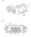
- a cooling fan includes: a fan housing 10 having an air discharge port 12 through which air is discharged therefrom and which is formed on the front surface thereof, and an air inlet 14 through which air flows thereinto and which is formed on the rear surface thereof; a rotary shaft 20 rotatably supported by the fan housing 10; a rotor 30 fixed to the rotary shaft 20; a stator 40 fixed to the fan housing 10 and disposed at a predetermined gap from the rotor 30; and an impeller 50 connected to the rotor 30 so as to rotate therewith.
- the fan housing 10 has a front surface and a rear surface open to allow air to pass through, and a support portion 60 to which the stator 40 is fixed and which is formed in the center thereof while the rotary shaft 20 is rotatably supported in the center thereof.
- the stator 40 includes a stator core 42 fixed to the outer circumferential surface of the support portion 60, a bobbin 44 mounted on the outer surface of the stator core 42, and a coil 46 wound around the bobbin 44 and through which electric power is applied.
- a printed circuit board (PCB) 70 is mounted on the lower side of the stator 40, and the PCB 70 is equipped with various circuit components required for cooling fan control and a Hall sensor for measuring the number of revolutions of the rotor 30.
- the coil 46 of the stator 40 is electrically connected to a cable for external power connection.
- the rotor 30 is disposed with a certain gap on the outer circumferential surface of the stator 40 and includes a magnet 32 formed in a cylindrical shape, a back yoke 34 disposed on the outer circumferential surface of the magnet 32, and a rotor support 36 to which the magnet 32 and the back yoke 34 are fixed and the impeller 50 is connected.
- the rotor support 36 includes a disk portion 72 having a rotary shaft 20 connected to the center thereof and formed in a disk shape, and a cylindrical portion 74 vertically extending from the edge of the disk portion 72, and on the inner surface of which the magnet 32 and the back yoke 34 are fixed, and on the outer surface of which the impeller 50 is formed.
- the impeller 50 is integrally formed with the rotor support 36 on the outer circumferential surface of the rotor support 36. That is, the impeller 50 and the rotor support 36 are formed by performing insert injection while the magnet 32, the back yoke 34, and the rotary shaft 20 are disposed in a mold, and the rotary shaft 20, the magnet 32 and the back yoke 34 are fixed on the rotor support 36.
- Fastening holes 64 for fixing a mounting bracket on which a cooling fan is mounted are formed at the corners of the fan housing 10.
- the fastening holes 64 are formed to penetrate through the corners of the fan housing 10 and can be used to fix the cooling fan to the mounting bracket by bolt fastening, bonding, or fitting.
- the support portion 60 is formed in a cylindrical shape in the center of the fan housing 10, and on the inner surface of which the rotary shaft 20 is rotatably inserted, and on the outer surface of which the stator 40 is fixed.
- the fan housing 10 is integrally molded by a mold and made of a resin material. That is, as shown in FIG. 5 , a connecting rib 62 and the supporting portion 60 are integrally formed with the fan housing 10 on the rear surface of the fan housing 10, and the lower surface of the supporting portion 60 is formed in a blocked state.
- the rotary shaft 20 is rotatably supported by a sleeve bearing 66 on the inner surface of the support portion 60, and a bushing 68 is mounted on the bottom surface of the support portion 60 in which the lower end of the rotary shaft 20 is rotatably contacted on the bottom surface of the support portion 60.
- the impeller 50 may be separated from the fan housing 10 when the impeller 50 is rotated because the rotary shaft 20 is vertically movably inserted into the support portion 60 and the sleeve bearing 66 is used.
- a separation prevention unit is installed on any one of the fan housing and the mounting bracket to prevent separation of the impeller 50.
- the separation prevention unit is equipped with a separation prevention member 80 on the front edge where an air discharge port 12 of the fan housing 10 is formed to prevent separation of the impeller 50.
- the separation preventing member 80 includes a fixing portion 82 fixed to a front edge at which the air discharge ort 12 of the fan housing 10 is formed, and a locking portion 84 protruding inwardly of the air discharge port 12 from the fixing portion 82 to block the rising of the impeller 50.
- the fixing portion 82 includes the same through holes 86 as the fastening holes 64 formed at the corners of the fan housing 10, and is fixed to the fan housing 10 by bolts or rivets. Then, the locking portion 84 protrudes a predetermined length toward the inside of the air discharge port 12 of the fan housing 10 to prevent the impeller 50 from being separated from the fan housing 10.
- the protruding length of the locking portion 84 prevents separation of the impeller 50 while minimizing the area blocking the air discharge port 12, thereby preventing separation of the impeller 50 without affecting the air discharge.
- the separation prevention member 80 may be formed of a metal material having strong strength, and may be installed in a plurality of pieces at regular intervals in the circumferential direction of the fan housing 10. As an example, the separation prevention member 80 may be mounted in two pieces on the edge of the fan housing 10 at intervals of 180 degrees, and four pieces at intervals of 90 degrees.
- the separation prevention member 80 is fixed to the edge of the fan housing 10 and is formed to protrude only a predetermined length in the inner direction of the air discharge port 12, thereby minimizing the area blocking the air discharge port 12 and preventing separation of the impeller 50.
- the separation prevention unit includes a separation prevention bar 100 formed in a mounting bracket 90 on which a cooling fan is mounted. Accordingly, when the cooling fan is mounted on the mounting bracket 90, the impeller 50 can be prevented from being separated, so that a separation prevention structure for preventing the impeller from being separated from the cooling fan is unnecessary, thereby simplifying the structure and simplifying the assembly process.
- the mounting bracket 90 communicates with the air discharge port 12 of the fan housing 10 to form an air passage portion 94 through which air passes, and a fastening protrusion 92 that is fastened to a fastening hole portion 64 formed in the fan housing 10 is formed at the edge of the mounting bracket 90.
- the separation prevention bar 100 is formed to extend inwardly from the edge of the air passage portion 94 to prevent the impeller 50 from being separated from the fan housing 10.
- the separation prevention bar 100 includes a pair of vertical bars 98 formed vertically at both edges of the air passage portion 94, and a horizontal bar 96 formed to connect between the pair of vertical bars 98 to prevent separation of the impeller 50.
- the vertical bars 98 play a role of maintaining a certain gap between the impeller 50 and the horizontal bar 96 so that the horizontal bar 96 does not interfere with the rotation of the impeller 50.
- the separation prevention unit integrally forms the separation prevention bar 100 when forming the mounting bracket 90, and the cooling fan does not need a separate part for preventing separation of the impeller, so the number of parts can be reduced and the assembly process can be simplified.
- the present invention can be usefully applied to cooling fans for preventing overheating of electronic devices, automobiles, LED lightings or the like.
Landscapes
- Engineering & Computer Science (AREA)
- Mechanical Engineering (AREA)
- General Engineering & Computer Science (AREA)
- Structures Of Non-Positive Displacement Pumps (AREA)
Claims (1)
- Kühlungsventilator umfassend:ein Ventilatorgehäuse (10), das an einer Befestigungshalterung (90) angebracht ist;eine Drehwelle (20), die drehbar durch das Ventilatorgehäuse (10) getragen ist;einen Rotor (30), der an der Drehwelle (20) fixiert ist;einen Stator (40), der an dem Ventilatorgehäuse (10) fixiert und mit einem vorbestimmten Abstand von einem Rotor (30) angeordnet ist, undein Laufrad (50), das mit dem Rotor (30) so verbunden ist, dass es mit ihm dreht, wobei eine Trennungsverhinderungsstange (100) in der Befestigungshalterung (90) ausgebildet ist, um zu verhindern, dass das Laufrad (50) von dem Ventilatorgehäuse (10) getrennt wird, wobei die Befestigungshalterung (90) einen Luftdurchgangsabschnitt aufweist, der mit einer Luftauslassöffnung (12) des Ventilatorgehäuses (10) in Verbindung steht, und die Trennungsverhinderungsstange (100) so ausgebildet ist, dass sie sich von einer Kante des Luftdurchgangsabschnitts nach innen erstreckt,
dadurch gekennzeichnet, dassdie Trennungsverhinderungsstange (100) ein Paar vertikaler Stangen (98) umfasst, die in einer vertikalen Richtung an einer Kante des Luftdurchgangsabschnitts so ausgebildet sind, dass sie so voneinander beabstandet sind, dass die Trennungsverhinderungsstange (100) die Drehung des Laufrads (50) nicht beeinträchtigt, undeine horizontale Stange (96) das Paar vertikaler Stangen (98) einstückig verbindet.
Applications Claiming Priority (2)
| Application Number | Priority Date | Filing Date | Title |
|---|---|---|---|
| KR1020170153057A KR20190056047A (ko) | 2017-11-16 | 2017-11-16 | 냉각 팬 |
| PCT/KR2018/013695 WO2019098618A1 (ko) | 2017-11-16 | 2018-11-12 | 냉각 팬 |
Publications (4)
| Publication Number | Publication Date |
|---|---|
| EP3712437A1 EP3712437A1 (de) | 2020-09-23 |
| EP3712437A4 EP3712437A4 (de) | 2021-07-28 |
| EP3712437B1 true EP3712437B1 (de) | 2024-05-15 |
| EP3712437C0 EP3712437C0 (de) | 2024-05-15 |
Family
ID=66540335
Family Applications (1)
| Application Number | Title | Priority Date | Filing Date |
|---|---|---|---|
| EP18878221.3A Active EP3712437B1 (de) | 2017-11-16 | 2018-11-12 | Kühlgebläse |
Country Status (5)
| Country | Link |
|---|---|
| US (2) | US20200271131A1 (de) |
| EP (1) | EP3712437B1 (de) |
| KR (1) | KR20190056047A (de) |
| CN (1) | CN111183292A (de) |
| WO (1) | WO2019098618A1 (de) |
Families Citing this family (6)
| Publication number | Priority date | Publication date | Assignee | Title |
|---|---|---|---|---|
| KR101990108B1 (ko) * | 2017-03-17 | 2019-06-18 | 주식회사 아모텍 | 쿨링 팬 및 이를 구비한 시트 쿨링장치 |
| KR102001004B1 (ko) * | 2017-12-06 | 2019-07-17 | 주식회사 아모텍 | 냉각 팬 |
| CN114076112B (zh) * | 2020-08-21 | 2025-03-04 | 亚浩电子五金塑胶(惠州)有限公司 | 发光风扇及散热装置 |
| WO2022092723A1 (ko) * | 2020-10-26 | 2022-05-05 | 주식회사 아모텍 | 냉각팬 |
| CN114412808B (zh) * | 2020-10-28 | 2024-08-23 | 亚浩电子五金塑胶(惠州)有限公司 | 散热装置 |
| CN113266588B (zh) * | 2021-06-18 | 2022-07-08 | 广东电网有限责任公司 | 一种变压器风扇 |
Citations (3)
| Publication number | Priority date | Publication date | Assignee | Title |
|---|---|---|---|---|
| US20120195738A1 (en) * | 2011-01-28 | 2012-08-02 | Hon Hai Precision Industry Co., Ltd. | Shockproof fan apparatus |
| US20140183328A1 (en) * | 2012-12-28 | 2014-07-03 | Hon Hai Precision Industry Co., Ltd. | Mounting apparatus for fan |
| US8801374B1 (en) * | 2009-10-07 | 2014-08-12 | Juniper Networks, Inc. | Fan trays having stator blades for improving air flow performance |
Family Cites Families (13)
| Publication number | Priority date | Publication date | Assignee | Title |
|---|---|---|---|---|
| JPH11252858A (ja) * | 1998-02-27 | 1999-09-17 | Matsushita Electric Ind Co Ltd | 電動機及びそれを用いたヒートシンク装置 |
| KR200319325Y1 (ko) * | 2003-04-19 | 2003-07-07 | 노시훈 | 착탈가능한 해충유인용 램프부를 구비한 환풍기 |
| CN2656685Y (zh) * | 2003-06-12 | 2004-11-17 | 鸿富锦精密工业(深圳)有限公司 | 风扇固定架 |
| US8109713B2 (en) * | 2009-03-24 | 2012-02-07 | Sunonwealth Electric Machine Industry Co., Ltd. | Heat-dissipating fan |
| KR101079050B1 (ko) | 2009-07-21 | 2011-11-02 | 주식회사 아모텍 | 분할 스큐 코어 구조의 스테이터, 이를 이용한 bldc 모터 및 배터리 쿨링장치 |
| KR101069575B1 (ko) * | 2009-10-26 | 2011-10-05 | 손청하 | 탈착식 팬망과 날개분리형 송풍날개 프레임이 구비되는 송풍팬 |
| CN201661487U (zh) * | 2010-01-04 | 2010-12-01 | 保锐科技股份有限公司 | 快拆式风扇及具有该风扇的机壳 |
| JP5728210B2 (ja) * | 2010-04-27 | 2015-06-03 | ミネベア株式会社 | 軸流ファン |
| US8449251B2 (en) * | 2010-10-12 | 2013-05-28 | Giga-Byte Technology Co., Ltd. | Fan module |
| KR20120083156A (ko) * | 2011-01-17 | 2012-07-25 | 호서대학교 산학협력단 | 선풍기 |
| CN103092294A (zh) * | 2011-10-31 | 2013-05-08 | 鸿富锦精密工业(武汉)有限公司 | 风扇模组 |
| TWI537480B (zh) * | 2012-07-09 | 2016-06-11 | 建準電機工業股份有限公司 | 鼓風式散熱扇 |
| KR20160030149A (ko) * | 2016-02-26 | 2016-03-16 | 김정훈 | 팬모터 구조를 갖는 초박형의 휴대단말용 냉각장치 |
-
2017
- 2017-11-16 KR KR1020170153057A patent/KR20190056047A/ko not_active Ceased
-
2018
- 2018-11-12 EP EP18878221.3A patent/EP3712437B1/de active Active
- 2018-11-12 CN CN201880064651.3A patent/CN111183292A/zh active Pending
- 2018-11-12 US US16/652,215 patent/US20200271131A1/en not_active Abandoned
- 2018-11-12 WO PCT/KR2018/013695 patent/WO2019098618A1/ko not_active Ceased
-
2022
- 2022-07-21 US US17/870,533 patent/US20220356887A1/en not_active Abandoned
Patent Citations (3)
| Publication number | Priority date | Publication date | Assignee | Title |
|---|---|---|---|---|
| US8801374B1 (en) * | 2009-10-07 | 2014-08-12 | Juniper Networks, Inc. | Fan trays having stator blades for improving air flow performance |
| US20120195738A1 (en) * | 2011-01-28 | 2012-08-02 | Hon Hai Precision Industry Co., Ltd. | Shockproof fan apparatus |
| US20140183328A1 (en) * | 2012-12-28 | 2014-07-03 | Hon Hai Precision Industry Co., Ltd. | Mounting apparatus for fan |
Also Published As
| Publication number | Publication date |
|---|---|
| EP3712437A4 (de) | 2021-07-28 |
| US20220356887A1 (en) | 2022-11-10 |
| KR20190056047A (ko) | 2019-05-24 |
| EP3712437A1 (de) | 2020-09-23 |
| CN111183292A (zh) | 2020-05-19 |
| WO2019098618A1 (ko) | 2019-05-23 |
| EP3712437C0 (de) | 2024-05-15 |
| US20200271131A1 (en) | 2020-08-27 |
Similar Documents
| Publication | Publication Date | Title |
|---|---|---|
| EP3712437B1 (de) | Kühlgebläse | |
| EP3723248B1 (de) | Kühlgebläse | |
| US9667115B2 (en) | Electronic housing for an electric motor with protection against accidental contact | |
| US11268527B2 (en) | Cooling fan | |
| US20090189492A1 (en) | Heat Dissipating Fan | |
| US10113551B2 (en) | Axial flow fan | |
| US20120201670A1 (en) | Blower fan | |
| CN110249137A (zh) | 风机 | |
| US11920601B2 (en) | Cooling fan | |
| US9531231B2 (en) | Radially offset motor control housing | |
| KR20080004155U (ko) | 청소기용 모터 | |
| JP6460957B2 (ja) | 遠心ファン | |
| KR101855685B1 (ko) | 배터리 냉각장치 | |
| US6939113B2 (en) | Fan with increased air flow | |
| JP6297467B2 (ja) | 遠心ファン | |
| US20110260032A1 (en) | Motor Base | |
| CN113137384B (zh) | 风扇及具有该风扇的电子装置 | |
| KR200441148Y1 (ko) | 청소기용 모터 | |
| KR102532539B1 (ko) | 팬 모터 및 이를 포함하는 차량 | |
| JP6342374B2 (ja) | 遠心ファン | |
| KR20180066929A (ko) | 브러시리스 팬 모터 및 이를 갖는 전자 기기 | |
| JP2019173735A (ja) | ファン装置 | |
| JP2019173734A (ja) | ファン装置 |
Legal Events
| Date | Code | Title | Description |
|---|---|---|---|
| STAA | Information on the status of an ep patent application or granted ep patent |
Free format text: STATUS: THE INTERNATIONAL PUBLICATION HAS BEEN MADE |
|
| PUAI | Public reference made under article 153(3) epc to a published international application that has entered the european phase |
Free format text: ORIGINAL CODE: 0009012 |
|
| STAA | Information on the status of an ep patent application or granted ep patent |
Free format text: STATUS: REQUEST FOR EXAMINATION WAS MADE |
|
| 17P | Request for examination filed |
Effective date: 20200402 |
|
| AK | Designated contracting states |
Kind code of ref document: A1 Designated state(s): AL AT BE BG CH CY CZ DE DK EE ES FI FR GB GR HR HU IE IS IT LI LT LU LV MC MK MT NL NO PL PT RO RS SE SI SK SM TR |
|
| AX | Request for extension of the european patent |
Extension state: BA ME |
|
| DAV | Request for validation of the european patent (deleted) | ||
| DAX | Request for extension of the european patent (deleted) | ||
| A4 | Supplementary search report drawn up and despatched |
Effective date: 20210629 |
|
| RIC1 | Information provided on ipc code assigned before grant |
Ipc: F04D 25/08 20060101AFI20210623BHEP Ipc: F04D 29/64 20060101ALI20210623BHEP Ipc: F04D 25/06 20060101ALI20210623BHEP Ipc: F04D 29/60 20060101ALI20210623BHEP Ipc: F04D 29/52 20060101ALI20210623BHEP |
|
| STAA | Information on the status of an ep patent application or granted ep patent |
Free format text: STATUS: EXAMINATION IS IN PROGRESS |
|
| 17Q | First examination report despatched |
Effective date: 20221020 |
|
| GRAP | Despatch of communication of intention to grant a patent |
Free format text: ORIGINAL CODE: EPIDOSNIGR1 |
|
| STAA | Information on the status of an ep patent application or granted ep patent |
Free format text: STATUS: GRANT OF PATENT IS INTENDED |
|
| INTG | Intention to grant announced |
Effective date: 20240301 |
|
| GRAS | Grant fee paid |
Free format text: ORIGINAL CODE: EPIDOSNIGR3 |
|
| GRAA | (expected) grant |
Free format text: ORIGINAL CODE: 0009210 |
|
| STAA | Information on the status of an ep patent application or granted ep patent |
Free format text: STATUS: THE PATENT HAS BEEN GRANTED |
|
| AK | Designated contracting states |
Kind code of ref document: B1 Designated state(s): AL AT BE BG CH CY CZ DE DK EE ES FI FR GB GR HR HU IE IS IT LI LT LU LV MC MK MT NL NO PL PT RO RS SE SI SK SM TR |
|
| REG | Reference to a national code |
Ref country code: CH Ref legal event code: EP |
|
| REG | Reference to a national code |
Ref country code: DE Ref legal event code: R096 Ref document number: 602018069640 Country of ref document: DE |
|
| REG | Reference to a national code |
Ref country code: IE Ref legal event code: FG4D |
|
| U01 | Request for unitary effect filed |
Effective date: 20240515 |
|
| U07 | Unitary effect registered |
Designated state(s): AT BE BG DE DK EE FI FR IT LT LU LV MT NL PT SE SI Effective date: 20240523 |
|
| PG25 | Lapsed in a contracting state [announced via postgrant information from national office to epo] |
Ref country code: IS Free format text: LAPSE BECAUSE OF FAILURE TO SUBMIT A TRANSLATION OF THE DESCRIPTION OR TO PAY THE FEE WITHIN THE PRESCRIBED TIME-LIMIT Effective date: 20240915 |
|
| PG25 | Lapsed in a contracting state [announced via postgrant information from national office to epo] |
Ref country code: HR Free format text: LAPSE BECAUSE OF FAILURE TO SUBMIT A TRANSLATION OF THE DESCRIPTION OR TO PAY THE FEE WITHIN THE PRESCRIBED TIME-LIMIT Effective date: 20240515 |
|
| PG25 | Lapsed in a contracting state [announced via postgrant information from national office to epo] |
Ref country code: GR Free format text: LAPSE BECAUSE OF FAILURE TO SUBMIT A TRANSLATION OF THE DESCRIPTION OR TO PAY THE FEE WITHIN THE PRESCRIBED TIME-LIMIT Effective date: 20240816 |
|
| PG25 | Lapsed in a contracting state [announced via postgrant information from national office to epo] |
Ref country code: ES Free format text: LAPSE BECAUSE OF FAILURE TO SUBMIT A TRANSLATION OF THE DESCRIPTION OR TO PAY THE FEE WITHIN THE PRESCRIBED TIME-LIMIT Effective date: 20240515 |
|
| PG25 | Lapsed in a contracting state [announced via postgrant information from national office to epo] |
Ref country code: PL Free format text: LAPSE BECAUSE OF FAILURE TO SUBMIT A TRANSLATION OF THE DESCRIPTION OR TO PAY THE FEE WITHIN THE PRESCRIBED TIME-LIMIT Effective date: 20240515 |
|
| PG25 | Lapsed in a contracting state [announced via postgrant information from national office to epo] |
Ref country code: PL Free format text: LAPSE BECAUSE OF FAILURE TO SUBMIT A TRANSLATION OF THE DESCRIPTION OR TO PAY THE FEE WITHIN THE PRESCRIBED TIME-LIMIT Effective date: 20240515 Ref country code: NO Free format text: LAPSE BECAUSE OF FAILURE TO SUBMIT A TRANSLATION OF THE DESCRIPTION OR TO PAY THE FEE WITHIN THE PRESCRIBED TIME-LIMIT Effective date: 20240815 Ref country code: IS Free format text: LAPSE BECAUSE OF FAILURE TO SUBMIT A TRANSLATION OF THE DESCRIPTION OR TO PAY THE FEE WITHIN THE PRESCRIBED TIME-LIMIT Effective date: 20240915 Ref country code: HR Free format text: LAPSE BECAUSE OF FAILURE TO SUBMIT A TRANSLATION OF THE DESCRIPTION OR TO PAY THE FEE WITHIN THE PRESCRIBED TIME-LIMIT Effective date: 20240515 Ref country code: GR Free format text: LAPSE BECAUSE OF FAILURE TO SUBMIT A TRANSLATION OF THE DESCRIPTION OR TO PAY THE FEE WITHIN THE PRESCRIBED TIME-LIMIT Effective date: 20240816 Ref country code: ES Free format text: LAPSE BECAUSE OF FAILURE TO SUBMIT A TRANSLATION OF THE DESCRIPTION OR TO PAY THE FEE WITHIN THE PRESCRIBED TIME-LIMIT Effective date: 20240515 Ref country code: RS Free format text: LAPSE BECAUSE OF FAILURE TO SUBMIT A TRANSLATION OF THE DESCRIPTION OR TO PAY THE FEE WITHIN THE PRESCRIBED TIME-LIMIT Effective date: 20240815 |
|
| U20 | Renewal fee for the european patent with unitary effect paid |
Year of fee payment: 7 Effective date: 20241122 |
|
| PG25 | Lapsed in a contracting state [announced via postgrant information from national office to epo] |
Ref country code: CZ Free format text: LAPSE BECAUSE OF FAILURE TO SUBMIT A TRANSLATION OF THE DESCRIPTION OR TO PAY THE FEE WITHIN THE PRESCRIBED TIME-LIMIT Effective date: 20240515 |
|
| PG25 | Lapsed in a contracting state [announced via postgrant information from national office to epo] |
Ref country code: RO Free format text: LAPSE BECAUSE OF FAILURE TO SUBMIT A TRANSLATION OF THE DESCRIPTION OR TO PAY THE FEE WITHIN THE PRESCRIBED TIME-LIMIT Effective date: 20240515 Ref country code: SK Free format text: LAPSE BECAUSE OF FAILURE TO SUBMIT A TRANSLATION OF THE DESCRIPTION OR TO PAY THE FEE WITHIN THE PRESCRIBED TIME-LIMIT Effective date: 20240515 |
|
| PG25 | Lapsed in a contracting state [announced via postgrant information from national office to epo] |
Ref country code: SM Free format text: LAPSE BECAUSE OF FAILURE TO SUBMIT A TRANSLATION OF THE DESCRIPTION OR TO PAY THE FEE WITHIN THE PRESCRIBED TIME-LIMIT Effective date: 20240515 |
|
| PG25 | Lapsed in a contracting state [announced via postgrant information from national office to epo] |
Ref country code: SM Free format text: LAPSE BECAUSE OF FAILURE TO SUBMIT A TRANSLATION OF THE DESCRIPTION OR TO PAY THE FEE WITHIN THE PRESCRIBED TIME-LIMIT Effective date: 20240515 Ref country code: SK Free format text: LAPSE BECAUSE OF FAILURE TO SUBMIT A TRANSLATION OF THE DESCRIPTION OR TO PAY THE FEE WITHIN THE PRESCRIBED TIME-LIMIT Effective date: 20240515 Ref country code: RO Free format text: LAPSE BECAUSE OF FAILURE TO SUBMIT A TRANSLATION OF THE DESCRIPTION OR TO PAY THE FEE WITHIN THE PRESCRIBED TIME-LIMIT Effective date: 20240515 Ref country code: CZ Free format text: LAPSE BECAUSE OF FAILURE TO SUBMIT A TRANSLATION OF THE DESCRIPTION OR TO PAY THE FEE WITHIN THE PRESCRIBED TIME-LIMIT Effective date: 20240515 |
|
| REG | Reference to a national code |
Ref country code: DE Ref legal event code: R097 Ref document number: 602018069640 Country of ref document: DE |
|
| PLBE | No opposition filed within time limit |
Free format text: ORIGINAL CODE: 0009261 |
|
| STAA | Information on the status of an ep patent application or granted ep patent |
Free format text: STATUS: NO OPPOSITION FILED WITHIN TIME LIMIT |
|
| 26N | No opposition filed |
Effective date: 20250218 |
|
| REG | Reference to a national code |
Ref country code: CH Ref legal event code: PL |
|
| PG25 | Lapsed in a contracting state [announced via postgrant information from national office to epo] |
Ref country code: MC Free format text: LAPSE BECAUSE OF FAILURE TO SUBMIT A TRANSLATION OF THE DESCRIPTION OR TO PAY THE FEE WITHIN THE PRESCRIBED TIME-LIMIT Effective date: 20240515 |
|
| REG | Reference to a national code |
Ref country code: CH Ref legal event code: PL |
|
| PG25 | Lapsed in a contracting state [announced via postgrant information from national office to epo] |
Ref country code: CH Free format text: LAPSE BECAUSE OF NON-PAYMENT OF DUE FEES Effective date: 20241130 |
|
| PG25 | Lapsed in a contracting state [announced via postgrant information from national office to epo] |
Ref country code: IE Free format text: LAPSE BECAUSE OF NON-PAYMENT OF DUE FEES Effective date: 20241112 |
|
| U20 | Renewal fee for the european patent with unitary effect paid |
Year of fee payment: 8 Effective date: 20251124 |
|
| PGFP | Annual fee paid to national office [announced via postgrant information from national office to epo] |
Ref country code: GB Payment date: 20251023 Year of fee payment: 8 |
|
| PG25 | Lapsed in a contracting state [announced via postgrant information from national office to epo] |
Ref country code: HU Free format text: LAPSE BECAUSE OF FAILURE TO SUBMIT A TRANSLATION OF THE DESCRIPTION OR TO PAY THE FEE WITHIN THE PRESCRIBED TIME-LIMIT; INVALID AB INITIO Effective date: 20181112 |
|
| PG25 | Lapsed in a contracting state [announced via postgrant information from national office to epo] |
Ref country code: CY Free format text: LAPSE BECAUSE OF FAILURE TO SUBMIT A TRANSLATION OF THE DESCRIPTION OR TO PAY THE FEE WITHIN THE PRESCRIBED TIME-LIMIT; INVALID AB INITIO Effective date: 20181112 |