EP3711923A1 - Nozzle assembly with pressure regulating device, granulating device and related method - Google Patents
Nozzle assembly with pressure regulating device, granulating device and related method Download PDFInfo
- Publication number
- EP3711923A1 EP3711923A1 EP20164252.7A EP20164252A EP3711923A1 EP 3711923 A1 EP3711923 A1 EP 3711923A1 EP 20164252 A EP20164252 A EP 20164252A EP 3711923 A1 EP3711923 A1 EP 3711923A1
- Authority
- EP
- European Patent Office
- Prior art keywords
- nozzle
- section
- nozzle arrangement
- regulating
- ring
- Prior art date
- Legal status (The legal status is an assumption and is not a legal conclusion. Google has not performed a legal analysis and makes no representation as to the accuracy of the status listed.)
- Granted
Links
- 230000001105 regulatory effect Effects 0.000 title claims abstract description 221
- 238000000034 method Methods 0.000 title claims abstract description 17
- 239000012530 fluid Substances 0.000 claims abstract description 62
- 239000000155 melt Substances 0.000 claims description 44
- 230000008878 coupling Effects 0.000 claims description 21
- 238000010168 coupling process Methods 0.000 claims description 21
- 238000005859 coupling reaction Methods 0.000 claims description 21
- 239000008187 granular material Substances 0.000 claims description 7
- 238000004519 manufacturing process Methods 0.000 claims description 4
- 230000033001 locomotion Effects 0.000 description 20
- 239000000463 material Substances 0.000 description 20
- 230000008569 process Effects 0.000 description 10
- XLYOFNOQVPJJNP-UHFFFAOYSA-N water Substances O XLYOFNOQVPJJNP-UHFFFAOYSA-N 0.000 description 8
- 238000013461 design Methods 0.000 description 7
- 230000008859 change Effects 0.000 description 6
- 238000005520 cutting process Methods 0.000 description 6
- 230000008901 benefit Effects 0.000 description 5
- 239000004033 plastic Substances 0.000 description 5
- 230000002829 reductive effect Effects 0.000 description 5
- 230000000694 effects Effects 0.000 description 4
- 238000005469 granulation Methods 0.000 description 4
- 230000003179 granulation Effects 0.000 description 4
- 238000010438 heat treatment Methods 0.000 description 4
- 230000000670 limiting effect Effects 0.000 description 4
- 230000036961 partial effect Effects 0.000 description 4
- 238000010586 diagram Methods 0.000 description 3
- 230000003993 interaction Effects 0.000 description 3
- 238000012545 processing Methods 0.000 description 3
- 238000007789 sealing Methods 0.000 description 3
- 230000006978 adaptation Effects 0.000 description 2
- 239000000853 adhesive Substances 0.000 description 2
- 230000001070 adhesive effect Effects 0.000 description 2
- 230000015572 biosynthetic process Effects 0.000 description 2
- 239000012809 cooling fluid Substances 0.000 description 2
- 238000006073 displacement reaction Methods 0.000 description 2
- 238000009826 distribution Methods 0.000 description 2
- 230000001681 protective effect Effects 0.000 description 2
- 230000009467 reduction Effects 0.000 description 2
- 230000007704 transition Effects 0.000 description 2
- 230000002411 adverse Effects 0.000 description 1
- 238000007906 compression Methods 0.000 description 1
- 230000006835 compression Effects 0.000 description 1
- 230000001276 controlling effect Effects 0.000 description 1
- 238000011161 development Methods 0.000 description 1
- 239000000428 dust Substances 0.000 description 1
- 230000002349 favourable effect Effects 0.000 description 1
- 230000001771 impaired effect Effects 0.000 description 1
- 239000007788 liquid Substances 0.000 description 1
- 238000012423 maintenance Methods 0.000 description 1
- 229920001169 thermoplastic Polymers 0.000 description 1
- 239000004416 thermosoftening plastic Substances 0.000 description 1
- 238000013519 translation Methods 0.000 description 1
Images


Classifications
-
- B—PERFORMING OPERATIONS; TRANSPORTING
- B29—WORKING OF PLASTICS; WORKING OF SUBSTANCES IN A PLASTIC STATE IN GENERAL
- B29C—SHAPING OR JOINING OF PLASTICS; SHAPING OF MATERIAL IN A PLASTIC STATE, NOT OTHERWISE PROVIDED FOR; AFTER-TREATMENT OF THE SHAPED PRODUCTS, e.g. REPAIRING
- B29C31/00—Handling, e.g. feeding of the material to be shaped, storage of plastics material before moulding; Automation, i.e. automated handling lines in plastics processing plants, e.g. using manipulators or robots
- B29C31/04—Feeding of the material to be moulded, e.g. into a mould cavity
-
- B—PERFORMING OPERATIONS; TRANSPORTING
- B29—WORKING OF PLASTICS; WORKING OF SUBSTANCES IN A PLASTIC STATE IN GENERAL
- B29C—SHAPING OR JOINING OF PLASTICS; SHAPING OF MATERIAL IN A PLASTIC STATE, NOT OTHERWISE PROVIDED FOR; AFTER-TREATMENT OF THE SHAPED PRODUCTS, e.g. REPAIRING
- B29C48/00—Extrusion moulding, i.e. expressing the moulding material through a die or nozzle which imparts the desired form; Apparatus therefor
- B29C48/25—Component parts, details or accessories; Auxiliary operations
- B29C48/30—Extrusion nozzles or dies
- B29C48/345—Extrusion nozzles comprising two or more adjacently arranged ports, for simultaneously extruding multiple strands, e.g. for pelletising
-
- B—PERFORMING OPERATIONS; TRANSPORTING
- B29—WORKING OF PLASTICS; WORKING OF SUBSTANCES IN A PLASTIC STATE IN GENERAL
- B29B—PREPARATION OR PRETREATMENT OF THE MATERIAL TO BE SHAPED; MAKING GRANULES OR PREFORMS; RECOVERY OF PLASTICS OR OTHER CONSTITUENTS OF WASTE MATERIAL CONTAINING PLASTICS
- B29B7/00—Mixing; Kneading
- B29B7/30—Mixing; Kneading continuous, with mechanical mixing or kneading devices
- B29B7/58—Component parts, details or accessories; Auxiliary operations
- B29B7/582—Component parts, details or accessories; Auxiliary operations for discharging, e.g. doors
-
- B—PERFORMING OPERATIONS; TRANSPORTING
- B29—WORKING OF PLASTICS; WORKING OF SUBSTANCES IN A PLASTIC STATE IN GENERAL
- B29B—PREPARATION OR PRETREATMENT OF THE MATERIAL TO BE SHAPED; MAKING GRANULES OR PREFORMS; RECOVERY OF PLASTICS OR OTHER CONSTITUENTS OF WASTE MATERIAL CONTAINING PLASTICS
- B29B9/00—Making granules
- B29B9/02—Making granules by dividing preformed material
- B29B9/06—Making granules by dividing preformed material in the form of filamentary material, e.g. combined with extrusion
- B29B9/065—Making granules by dividing preformed material in the form of filamentary material, e.g. combined with extrusion under-water, e.g. underwater pelletizers
-
- B—PERFORMING OPERATIONS; TRANSPORTING
- B29—WORKING OF PLASTICS; WORKING OF SUBSTANCES IN A PLASTIC STATE IN GENERAL
- B29B—PREPARATION OR PRETREATMENT OF THE MATERIAL TO BE SHAPED; MAKING GRANULES OR PREFORMS; RECOVERY OF PLASTICS OR OTHER CONSTITUENTS OF WASTE MATERIAL CONTAINING PLASTICS
- B29B9/00—Making granules
- B29B9/10—Making granules by moulding the material, i.e. treating it in the molten state
-
- B—PERFORMING OPERATIONS; TRANSPORTING
- B29—WORKING OF PLASTICS; WORKING OF SUBSTANCES IN A PLASTIC STATE IN GENERAL
- B29C—SHAPING OR JOINING OF PLASTICS; SHAPING OF MATERIAL IN A PLASTIC STATE, NOT OTHERWISE PROVIDED FOR; AFTER-TREATMENT OF THE SHAPED PRODUCTS, e.g. REPAIRING
- B29C48/00—Extrusion moulding, i.e. expressing the moulding material through a die or nozzle which imparts the desired form; Apparatus therefor
- B29C48/001—Combinations of extrusion moulding with other shaping operations
- B29C48/0022—Combinations of extrusion moulding with other shaping operations combined with cutting
-
- B—PERFORMING OPERATIONS; TRANSPORTING
- B29—WORKING OF PLASTICS; WORKING OF SUBSTANCES IN A PLASTIC STATE IN GENERAL
- B29C—SHAPING OR JOINING OF PLASTICS; SHAPING OF MATERIAL IN A PLASTIC STATE, NOT OTHERWISE PROVIDED FOR; AFTER-TREATMENT OF THE SHAPED PRODUCTS, e.g. REPAIRING
- B29C48/00—Extrusion moulding, i.e. expressing the moulding material through a die or nozzle which imparts the desired form; Apparatus therefor
- B29C48/25—Component parts, details or accessories; Auxiliary operations
- B29C48/255—Flow control means, e.g. valves
- B29C48/2556—Flow control means, e.g. valves provided in or in the proximity of dies
-
- B—PERFORMING OPERATIONS; TRANSPORTING
- B29—WORKING OF PLASTICS; WORKING OF SUBSTANCES IN A PLASTIC STATE IN GENERAL
- B29C—SHAPING OR JOINING OF PLASTICS; SHAPING OF MATERIAL IN A PLASTIC STATE, NOT OTHERWISE PROVIDED FOR; AFTER-TREATMENT OF THE SHAPED PRODUCTS, e.g. REPAIRING
- B29C48/00—Extrusion moulding, i.e. expressing the moulding material through a die or nozzle which imparts the desired form; Apparatus therefor
- B29C48/25—Component parts, details or accessories; Auxiliary operations
- B29C48/92—Measuring, controlling or regulating
-
- B—PERFORMING OPERATIONS; TRANSPORTING
- B29—WORKING OF PLASTICS; WORKING OF SUBSTANCES IN A PLASTIC STATE IN GENERAL
- B29C—SHAPING OR JOINING OF PLASTICS; SHAPING OF MATERIAL IN A PLASTIC STATE, NOT OTHERWISE PROVIDED FOR; AFTER-TREATMENT OF THE SHAPED PRODUCTS, e.g. REPAIRING
- B29C37/00—Component parts, details, accessories or auxiliary operations, not covered by group B29C33/00 or B29C35/00
- B29C2037/90—Measuring, controlling or regulating
-
- B—PERFORMING OPERATIONS; TRANSPORTING
- B29—WORKING OF PLASTICS; WORKING OF SUBSTANCES IN A PLASTIC STATE IN GENERAL
- B29C—SHAPING OR JOINING OF PLASTICS; SHAPING OF MATERIAL IN A PLASTIC STATE, NOT OTHERWISE PROVIDED FOR; AFTER-TREATMENT OF THE SHAPED PRODUCTS, e.g. REPAIRING
- B29C2948/00—Indexing scheme relating to extrusion moulding
- B29C2948/92—Measuring, controlling or regulating
- B29C2948/92504—Controlled parameter
- B29C2948/92514—Pressure
Definitions
- the invention relates to a nozzle arrangement for a granulating device, with a pressure regulating device coupled to the nozzle body, comprising a base body with a fluid inlet side and a fluid outlet side, a flow channel formed in the base body for the fluid-conducting connection of the fluid inlet side with the fluid outlet side and an annular channel section connected to the flow channel in a fluid-conducting manner and formed in the region of the fluid outlet side.
- Such nozzle arrangements are known in the prior art and are used, for example, in granulating devices. They are used to extrude molten granulating material, such as thermoplastics, by means of a nozzle plate in the form of mostly several strands of melt. As part of the so-called underwater granulation process, the individual melt strands are then divided into strand sections by means of a cutting device, which, when they come into contact with a cooling fluid, for example water, are cooled and thus form granules.
- a cooling fluid for example water
- melt is fed into a nozzle body on an inlet side.
- the melt is guided through the nozzle body by means of a large number of flow channels and reaches a nozzle plate.
- the nozzle plate typically has a large number of nozzle holes in order to achieve high productivity and, depending on the melt to be processed, a desired granulation result - that is, high throughputs or small granules.
- this has the disadvantage that, in particular, the nozzle bodies and the nozzle plates are each designed for specific throughputs and viscosities of plastic melts.
- Each material or each melt is typically to be processed with advantageous process parameters, such as a predetermined processing pressure, in order to ensure that the melt strands emerge from the nozzle plate in a desired manner.
- process parameters such as a predetermined processing pressure
- material changes typically result in the complete nozzle arrangement being exchanged and having to be kept ready for each material to be processed or at least for material groups of different nozzle arrangements. If different materials are to be processed, this results in a high capital commitment, since a large number of nozzle arrangements have to be kept available.
- replacing a nozzle arrangement is typically time-consuming, which means that changing the material to be processed is associated with high set-up costs.
- the DE 20 2006 018 456 U1 a nozzle head of a plastic strand pelletizer.
- the relevant nozzle head has a melt inlet opening for receiving melt from an extruder and a melt distributor for distributing melt from the melt inlet opening to a plurality of melt ducts with nozzles opening towards one end for the exit of molten plastic strands, the nozzle head having a plurality of between the melt inlet opening and the nozzles arranged bottlenecks for the flow of melt, which are variable and individually adjustable in their cross section.
- the invention was based on the object of developing a nozzle arrangement of the type described at the outset in such a way that the disadvantages found in the prior art are eliminated as far as possible.
- a nozzle arrangement was to be specified which can be used for a large number of different materials, material throughputs and viscosities and at the same time can be produced inexpensively and is functionally reliable and easy to maintain.
- the object is achieved in a nozzle arrangement of the type mentioned by a flow cross-section regulating element movable relative to the annular channel section and / or the flow channel for influencing a flow cross-section of the annular channel section.
- the invention makes use of the knowledge that the movement of an individual component or of a subassembly, which is narrowly limited in terms of its number of components, can be used to change the free flow cross-section of a relevant annular channel section of a nozzle arrangement in such a way that different materials are involved with such a nozzle arrangement different throughputs and viscosities can be processed.
- Such a flow cross section regulating element can in particular be used to influence the free flow cross section in an annular channel section which, for example, supplies a large number of flow channels with melt.
- the flow cross-section regulating element can be movable relative to a flow channel.
- a single flow cross-section regulating element can thus be used to indirectly influence the melt pressure in an entire nozzle arrangement.
- the free flow cross-section and the melt pressure are also influenced in the immediate vicinity of the nozzle plate from which the melt strands emerge.
- overall the melt pressure can be adjusted very precisely, while at the same time the component complexity of the device according to the invention is low and it is easy to maintain.
- the cost efficiency can be increased significantly by means of the pressure regulating device according to the invention.
- the invention is further developed in that the regulating element is arranged in the annular channel section.
- the regulating element is preferably surrounded by melt.
- the regulating element can now be used to influence the gap between the regulating element and the annular channel section and thus the free flow cross section by moving the regulating element relative to the annular channel section. This results in the advantage that the free flow cross section and thus indirectly the pressure conditions in the melt can be influenced in a very finely dosed manner.
- Such an arrangement also ensures that the melt flow is impaired as little as possible, in particular that strong vortex formation is reliably prevented.
- the regulating element has a regulating ring and a retaining ring connected to the regulating ring.
- a two-piece structure enables the regulating ring to be easily exchanged and to be adapted as required to, for example, different materials, throughputs or viscosities. Simple replacement of the individual components is also guaranteed in the event of wear.
- Regulating ring and retaining ring can be connected in many ways. For example, a screw connection, a heat-resistant adhesive connection or a form-fitting connection are possible.
- the invention is further developed in that the regulating ring is wedge-shaped.
- a wedge shape of the regulating ring has proven to be particularly favorable for influencing the free flow cross section without adversely affecting the melt flow, for example through the formation of eddies.
- the regulating ring can have concave and / or convex sections for targeted influencing of the flow or it can be designed in a flow-favorable manner in some other way.
- the regulating ring has pins which, depending on the position of the regulating ring, extend at least in sections into the annular channel section.
- the additional use of such pins also referred to as pressure regulating pins, enables an additional restriction of the free flow cross-section in certain areas, so that the pressure of the melt is increased by means of such pins Pens can also influence.
- the pins can be dimensioned in such a way that they in particular extend into the flow channels formed in the nozzle body. In this way, the area of the pressure influencing can be shifted closer in the direction of the nozzle disk.
- the quality of the melt strands can be positively influenced.
- the nozzle arrangement preferably has at least one actuator connected to the regulating element for moving the regulating element relative to the annular channel section, in particular in a translational direction along a longitudinal axis of the base body.
- the nozzle arrangement preferably has three or more such actuators in order to ensure that the regulating element in the area of the ring channel has a distance from the lateral boundaries of the ring channel that is as constant as possible over the course of the ring channel. In particular, it must be ensured in any case that tilting of the regulating element is prevented and thus indirectly an uneven melt discharge from the nozzle plate.
- the actuator is designed as a fluid-operated actuator, in particular as a pneumatic actuator or hydraulic actuator.
- the design of the actuator as a fluid-operated actuator has proven to be preferable for applications in which the number of mechanical components is to be reduced and at the same time a low-wear actuator is to be used.
- the fluid-actuated actuator preferably has a cylinder with at least one pressure fluid inlet / outlet, the cylinder and the at least one pressure fluid inlet / outlet being formed in the base body.
- the number of components required can be further reduced by designing the cylinder in the base body.
- a piston, which is sealed off from the cylinder by means of a bellows, is preferably arranged in the cylinder. This ensures a durable and secure seal.
- the actuator is preferably designed such that it has a pin which is connected to the retaining ring and which is operatively connected to a translationally movable plunger.
- the arrangement described enables the position of the retaining ring or the regulating element to be set sensitively while at the same time being structurally simple.
- the base body has at least one bearing bore for mounting the plunger and for guiding the plunger to an outside of the base body.
- This bearing bore preferably has a seal to prevent melt from escaping from the housing.
- the tappet has an actuating element, in particular a nut or a gear arranged outside the housing, which preferably corresponds to an external thread of the tappet.
- Such an actuating element arranged outside the housing enables the regulating element to be actuated in a simple manner and it is ensured that melt cannot escape from the housing.
- the type of actuating element can be selected flexibly overall and depends in particular on how it is to be controlled.
- the actuating element can have devices for manual actuation, or machine elements such as nuts or gears.
- the invention is further developed by a coupling device for coupling the actuating elements of at least two actuators.
- the coupling device is preferably designed as a ring gear which is in engagement with the actuating elements, in particular the gearwheels, of the plurality of actuating elements, so that actuation of the ring gear causes actuation of the plurality of actuating elements.
- This is based on the principle that the actuation of a single coupling device actuates several actuators of a nozzle arrangement, in particular synchronously.
- the actuators themselves or a group of actuators, which can be coupled in any way can be operated individually or in groups by means of a motor drive, a pneumatic drive, an electric drive, or a linear drive.
- the actuating elements or the coupling device have a drive and / or a hand lever.
- a drive and / or a hand lever In particular, an electric motor, a pneumatic drive, or a linear drive can be used as the drive.
- a hand lever provides a particularly inexpensive means of actuation, which, however, requires direct interaction by an operator. Actuation of the coupling device by means of a drive makes it possible to automate the nozzle arrangement with regard to the actuation of the regulating element.
- the regulating element is designed as a sleeve, the sleeve surrounding the main body at least in sections and being translationally movable in the direction of the longitudinal axis of the main body, a regulating section being formed on the regulating element which is designed to influence the free flow cross-section in the annular channel section .
- the design of the regulating element as a sleeve or sleeve-shaped body has also been shown to be suitable for targeted influencing of the free flow cross-section in the annular channel section.
- This alternative embodiment is accompanied by a further reduced number of components, and due to the structural design of the regulating element as a sleeve, large forces can be applied to the regulating section of the regulating element.
- the translational displacement of the sleeve takes place by means of a screw introduced into the base body.
- the sleeve has a corresponding screw receptacle, the receptacle having a recess for inserting an actuating nut which can be screwed onto the screw.
- the actuating nut is limited in both actuating directions of the sleeve, so that a rotation of the nut causes the sleeve to be moved in a translatory manner in the direction of the longitudinal axis of the main body and in the relevant opposite direction. At least three such actuation screws are preferably arranged in the base body.
- the regulating section is preferably designed in a wedge shape.
- the regulating section can also have concave or convex sections and a combination thereof with straight sections.
- the shape of the control section can be adapted to the material to be processed, its viscosity and the desired throughput.
- the regulating section has pins which, depending on the position of the regulating section relative to the ring channel section, extend at least in sections into the ring channel section.
- the regulating element has pins which, depending on the position of the regulating element, extend at least in sections into the annular channel section.
- the pins can have different lengths and shapes in different exemplary embodiments. According to a first exemplary embodiment, it is provided that the pins extend essentially into the annular channel section and, moreover, especially in the state in which the pins are moved in the direction of the nozzle plate, additionally at least in a partial area of the flow channels of the nozzle unit. In a further exemplary embodiment it is provided that slightly longer pins are used, which likewise extend into the annular channel section and into a larger sub-area of the flow channels of the nozzle unit. In this way, the pressure conditions in the immediate vicinity of the nozzle plate can be adjusted in a targeted manner depending on the melt to be processed (viscosity, throughput).
- the pins taper in the direction of the nozzle plate.
- the pins have two sections, a first section having a constant diameter and a second section of the pin tapering in the direction of the nozzle plate.
- the end of the pins facing the nozzle plate is designed as a point or as a curve.
- the pins have an external thread on the side facing away from the nozzle plate, which corresponds to an internal thread which is introduced into the regulating section or the regulating element.
- the pins can thus preferably be screwed into the regulating section or the regulating element.
- the regulating section and the regulating element have bores into which the pins can be introduced.
- the number of pins which are arranged on the regulating section or on the regulating element is variable.
- the pressure conditions in the annular channel section or in the flow channel of the nozzle unit can be influenced in a targeted manner.
- the flow cross-section regulating element is designed as a cone that can be moved translationally with respect to a main body longitudinal axis.
- An actuator for translational movement of the cone is preferably assigned to the cone.
- the actuator is designed as a fluid-operated actuator, particularly preferably as a pneumatic actuator and hydraulic actuator.
- the actuator is designed as a mechanical actuator.
- a design in this regard is particularly preferable when no print medium is available in a production environment.
- the mechanical actuator has a threaded pin which can be brought into engagement with an internal thread arranged in the cone for translational movement of the cone.
- the mechanical actuator has an adjusting pin which is operatively connected to a rotary body via a gear, and the rotary body is operatively connected to the cone by means of a thread.
- the translationally movable cone is preferably guided and sealed with respect to the base body and / or the nozzle plate by means of a conical guide. This ensures that the cone is guided uniformly and centered with respect to the base body and / or the nozzle plate.
- the cone has, on its side facing the annular channel section, a trapezoidal section for influencing the flow cross section in the annular channel section.
- the cone is thus set up to directly influence the flow conditions in the area of the annular channel section through the trapezoidal section.
- the translationally movable cone is sealed off from the base body and / or the nozzle plate by means of a bellows, the bellows being set up to influence the flow cross section in the annular channel section.
- the bellows In a first operating position of the cone, the bellows is preferably in close contact with the outer circumference of the cone, whereas in a second position of the cone the bellows is curved, which is suitable for influencing the flow conditions in the annular channel section.
- the invention is further developed in that the pressure regulating device is coupled to a nozzle body.
- the pressure regulating device and the nozzle body thus form a nozzle unit.
- the pressure regulating device is formed in a nozzle body.
- a particular advantage here is that an overall more compact arrangement of the pressure regulating device and nozzle body can be achieved.
- the nozzle body has a guide arrangement for guiding the flow cross-section regulating element relative to the nozzle body.
- the flow cross-section regulating element is aligned and guided concentrically relative to the nozzle body by the guide arrangement.
- the guide arrangement preferably comprises several, in particular three, guide plates arranged concentrically on the nozzle body, which guide the flow cross-section regulating element, in particular on its inner radius or outer radius.
- the flow cross section regulating element has at least one guide element for guiding the flow cross section regulating element relative to the nozzle body, and the nozzle body has at least one guide groove in which the at least one guide element is movably received.
- the flow cross-section regulating element has throttle pins, the throttle pins being guided and received in radially outwardly extending guides in the nozzle body and extending at least in sections into the annular channel section.
- the throttle pins are inserted so far into the annular channel section that it is almost completely blocked. It is also preferred that the throttle pins can be moved into a further position in which they virtually do not protrude into the annular channel section and thus do not or only slightly influence the free flow cross section in the annular channel section.
- the flow cross-section regulating element has at least one slide element with at least one slide bore, the slide element being able to be brought into a position in which the slide bore is aligned with the nozzle body flow channels and in a further position in which the slide bore is not or only partially is aligned with the nozzle body flow channels.
- slides that have bores are used to influence the flow in the area of the nozzle body flow channels. If the bore in the slide elements is aligned with the nozzle body flow channels, the flow through the nozzle body flow channels is virtually unaffected. If the slide elements - and thus also the slide bores received therein - are brought out of alignment, the flow conditions in the nozzle body flow channels are influenced.
- the slide elements are operatively connected to a slide rod, which are guided and received in guides extending radially outward in the nozzle body.
- the slide rods are thus easily accessible and actuated from outside the nozzle body.
- the slide elements are coupled to a rotationally movable slide adjustment device. This enables a sensitive variation of the position of the slide elements.
- the flow cross-section regulating element is designed as a throttle element which can be selectively pivoted into the flow channel.
- the invention is further developed in that the throttle element is mounted pivotably about an axis of rotation and is held in a pivot position by an adjusting screw.
- the use of such pivot elements which are typically due to the fluid pressure to the outside and thus are preferably pressed against an adjusting screw, has proven to be particularly suitable for sensitive adjustment of the flow conditions.
- the throttle elements have wedge-shaped sections, concave or convex sections, or combinations thereof.
- the invention has been described above with reference to a nozzle arrangement.
- the invention relates to a granulating device for producing granules from a melt flow with a nozzle arrangement. The invention solves the problem identified at the outset in relation to the granulating device in that the nozzle arrangement is designed according to one of the above aspects.
- the invention relates to a method for regulating the pressure of a melt flow.
- the invention achieves the object specified at the beginning with reference to a method which has the following steps: providing a melt flow to a pressure regulating device, directing the melt flow to an annular channel section of the pressure regulating device and regulating the free flow cross section of the annular channel section.
- the free flow cross section of a flow channel of a nozzle unit is also regulated.
- Fig. 1 shows a granulating device 2, which in the present case and preferably is designed as an underwater granulating device; however, the exemplary embodiments according to the invention can also be used in other granulating devices or processes.
- the granulating device 2 has a drive 6 which provides drive power to an underwater granulator 14.
- the granulating device 2 also has a protective hood 16.
- the nozzle arrangement 4 is supplied with liquid plastic melt typically by means of an extruder (not shown in the figures).
- the nozzle arrangement 4 has a pressure regulating device 26 and a nozzle unit 28.
- the melt is fed to the pressure regulating device 26 and, depending on the material of the melt, its viscosity and the intended material throughput, is regulated, in particular with regard to the melt pressure, and fed to the nozzle unit 28.
- the nozzle arrangement 4 is heated electrically or by means of a heating fluid.
- process water can be introduced into the nozzle arrangement 4 by means of a process water inlet 24 and can leave the same via the process water outlet 12.
- the melt occurs in the form of melt strands (in Fig.
- melt strand sections come into contact with a cooling fluid, in particular water, in the underwater granulator 14 and are abruptly cooled.
- the melt strands are cut and form granules that are separated from the water as granules in the further course of the process.
- the drive 6 is used in particular to drive the cutting device, which is kept available for separating the melt strands into strand sections.
- the assembly of drive 6, underwater granulator 14 and nozzle arrangement 4 with nozzle unit 28 and pressure regulating device 26 is arranged on a machine carrier 20. This is in turn coupled by means of the spacing elements 22 to a base plate 18, which in turn is connected to a housing 8.
- the housing 8, in turn, is arranged on a base section 10, which has, for example, rollers for easier positioning of the granulating device 2.
- Fig. 2 shows the in Fig. 1
- the nozzle arrangement 4 shown in a state separated from the granulating device 2.
- the nozzle arrangement 4 has the pressure regulating device 26 and the nozzle unit 28.
- the nozzle unit 28 contains a nozzle body 38 and a nozzle plate 40.
- the nozzle plate 40 has nozzle holes 42 from which strands of melt emerge from the nozzle unit 28.
- the pressure regulating device 26 is coupled to the nozzle unit 28.
- the pressure regulating device 26 has a base body 30 and a housing section 31. Melt arrives at the fluid inlet side 32 in the base body 30.
- the Fig. 2 the actuators 34 can also be seen, which by means of the actuating nuts 36 enable the free flow cross-section to be influenced in a partial area of the pressure regulating device 26 and thus indirectly to influence the melt pressure.
- FIG. 3 the pressure regulating device 26 is now shown without the nozzle unit 28, wherein the fluid outlet side 48 of the pressure regulating device 26 can be seen.
- a flow channel 46 is formed within the base body 30 of the pressure regulating device 26. This is limited in the area of the fluid outlet side 48 in the present embodiment by a translationally displaceable sleeve 44. By moving the sleeve 44 together with the nozzle unit 28, not shown here, the free flow cross-section in the area of the fluid outlet side 48 can be influenced, as shown in detail in the following figures.
- the nozzle arrangement 4 has the pressure regulating device 26 and the nozzle unit 28.
- the nozzle unit 28 in the present case consists of a nozzle body 38 in which nozzle body flow channels are introduced. These nozzle body flow channels 60 are arranged on a circular ring around the longitudinal axis of the nozzle body 38.
- a guide cone 58 is attached to the nozzle body 38. This is centered in particular by the centering pin 54 and coupled to the nozzle body 38 by means of a conical fastening screw 56.
- On the exit side A nozzle plate 40 is attached to the nozzle body 38, which the nozzle holes 42 (cf. Fig. 2 ) has, from which melt strands emerge from the arrangement.
- the pressure regulating device 26 is coupled to the nozzle unit 28.
- This has a base body 30 in which a flow channel 46 is formed.
- the flow channel 46 is arranged centered relative to the longitudinal axis in the middle of the base body 30.
- an annular channel gate 50 is formed by the interaction of the flow channel 46 with the guide cone 58 of the nozzle unit 28.
- a sleeve 44 with a regulating section 52 is arranged in the area thereof. The sleeve 44 is mounted such that it can be displaced in translation along the longitudinal axis of the base body 30.
- a housing section 31 is arranged on the fluid outlet side 48 of the pressure regulating device 26. This runs essentially in a ring around the base body 30 and the sleeve 44.
- the housing section 31 is additionally connected to the base body 30 by means of the screw 62. At its end facing away from the screw head, the screw 62 is screwed into the base body 30 in sections and secured to it by means of the fastening nut 66. The preferably several screws 62 thus additionally connect the base body 30 to the housing section 31.
- the sleeve 44 has bores, the diameter of which corresponds to the diameter of the screw 62.
- the sleeve 44 has a recess for introducing an actuating nut 36.
- the sleeve 44 is placed on the screws 62 and the nut 36 is screwed onto the screw 62. Due to the shape of the receiving section for the actuating nuts 36, actuation of the actuating nuts 36 results in the sleeve 44 in contact with the actuating nut 36 moving translationally when the actuating nut 36 rotates when the housing section 31 is fixedly arranged relative to the base body 30.
- the actuating nut 36 which is assigned to an actuator 34 are, adjust the position of the sleeve 44 translationally.
- the free flow cross section in the annular channel section 50 can thus be influenced.
- This adaptation of the free flow cross section in the annular channel section 50 results in an indirect regulation of the melt pressure.
- the range of motion of the sleeve 44 is limited by a first limiting shoulder 70 and a second limiting shoulder 72.
- Fig. 5 shows an operating state of the nozzle arrangement 4 in which the sleeve 44 has been displaced translationally in the direction of the nozzle body 38.
- the free interference cross-section 50 is now restricted in the direct transition to the nozzle body 38 of the nozzle unit 28.
- Such a restriction of the free flow cross section in the annular channel section 50 can, for example, lead to an increase in the pressure of the melt compared to that in FIG Fig. 4 state shown.
- the structure of the nozzle arrangement 4, as shown in FIGS Figures 6 to 7 shown, is fundamentally based on that from the Figures 4 and 5 known structure.
- the sleeve 44 or the regulating section 52 of the sleeve 44 has a number of pins 74.
- the positioning of the pins 74 now also offers the possibility of influencing the free flow cross section and thus indirectly the pressure conditions, particularly in the annular channel section 50, but also in the nozzle body flow channels 60.
- the pins 74 can for example be screwed to the sleeve 44, glued or introduced into the same by means of a press fit.
- pins 74 and sleeve 44 can be formed in one piece.
- the number of pins 74 is variable overall and can also be adapted to a material to be processed, a relevant viscosity or a desired material throughput.
- Fig. 6 shows the state in which the sleeve 44 including the pins 74 is in a position moved away from the nozzle body 38.
- the control section 52 does not restrict the free disturbance cross-section in the ring channel section 50 in this operating position, but the pins 74 are already at least partially inserted into the ring channel section 50 and the nozzle body flow channels 60.
- the one in the Fig. 7 In the state shown, the sleeve 44 has now been moved translationally in the direction of the nozzle body 38. This has the consequence that the control section 52 limits the free flow cross section in the annular channel section 50 and at the same time the pins 74 limit the free flow cross section in the area of the Limit annular channel section 50 and also in the area of the nozzle body flow channels 60.
- FIG Fig. 8 An alternative embodiment of a nozzle assembly 104 is shown in FIG Fig. 8 shown.
- the nozzle arrangement 104 has an alternative exemplary embodiment of a pressure regulating device 126 as well as the already known nozzle unit 28.
- the nozzle unit 28 has a nozzle body 38 and a nozzle plate 40 with nozzle holes 42.
- the pressure regulating device 126 is connected to the nozzle unit 28.
- This has a base body 130 to which a coupling device 188 with a hand lever 182 is attached. A movement of the hand lever 182 along the circumference of the base body 130 leads to a change in the free flow cross section in the annular channel section 150 or in the nozzle body flow channels 60, as can be seen in detail in the following figures.
- the pressure regulating device 126 which is arranged on the nozzle unit 28.
- the pressure regulating device 126 has a base body 130 in which a flow channel 146 is arranged. Together with the guide cone 58 of the nozzle unit 28, the flow channel 146 forms an annular channel section 150.
- a regulating ring 186 is arranged in this annular channel section 150. In particular, a translational movement of this regulating ring 186 in the direction of the nozzle unit 28 (or in the opposite direction) can influence the free flow cross section in the annular channel section 150.
- a movement of the regulating ring 186 in the direction of the nozzle unit 28 leads to the free flow cross section in the annular channel section 150 being reduced.
- the regulating ring 186 is arranged on a retaining ring 184.
- the relevant components can, for example, be glued to one another, screwed, or connected in some other way, possibly also made in one piece.
- An actuating element 176 is attached to the retaining ring 184 in a form-fitting or force-fitting manner. Typically, a plurality of actuating elements 176 are attached to the retaining ring 184, only one being shown here due to the sectional illustration.
- the actuating element 176 is in turn connected to a tappet 178.
- the tappet 178 has, at its end opposite the retaining ring 184, a threaded section to which an actuating element 180 is applied.
- the range of motion of the Actuating element 180 is limited on one side by the base body 130 and on the other side by an end ring 190.
- a translational movement of the actuating element 180 is therefore inhibited in the present case. This has the consequence that a rotation of the actuating element 180 results in the plunger 178 moving translationally in the direction of the nozzle body 38 or away from it. Since the regulating ring 186 is indirectly connected to the plunger 178, a rotation of the actuating element 180 causes a translatory movement of the regulating ring 186, with which finally the free flow cross section in the annular channel section 150 can be regulated.
- the pressure regulating device 126 preferably has several, in particular three, tappets 178.
- the actuating elements 180 are preferably designed as gear wheels, which correspond to a coupling device 188, which is designed in particular as a ring gear.
- a rotation of the coupling device 188 along the circumference of the base body 130 leads to the multiple actuating elements 180 being moved uniformly, which can ensure that the regulating ring 186 is moved uniformly and as purely translationally as possible in the direction of the nozzle body 38 or away from it.
- a hand lever 182 is arranged on the coupling device 188 to facilitate manual actuation of the coupling device 188.
- FIGS 10 and 11 are different operating states of the nozzle arrangement 104 from FIG Fig. 9 shown.
- Fig. 10 shows an operating state in which the regulating ring 186 has been moved as far as possible in a direction opposite to the nozzle body 38.
- the free flow cross section in the annular channel section 150 is thus at a maximum.
- Fig. 11 that state is shown in which the regulating ring 186 has been moved as far as possible in the direction of the nozzle body 38.
- the free flow cross section in the annular channel section 150 is minimal. It is provided, however, that a certain free flow cross section always remains between regulating ring 186 and annular channel section 150.
- Fig. 12 shows the nozzle arrangement of FIG Figs. 8-11 , however, pins 174 for influencing the free cross section in the annular channel section 150 or in the nozzle body flow channels 60 are arranged on the regulating ring 186.
- the pins 174 can be connected to the retaining ring 184 or the regulating ring 186 in different ways. For example, the components can be screwed, glued, otherwise connected, or formed in one piece. In addition, the number of pins 174 is variable, as is their geometry and length. Referring to the Fig. 12 actuation of the coupling device 188 now results in the actuation element 180 also rotating.
- pins 174 are presently arranged on the retaining ring 184 or the regulating ring 186, they are moved in the direction of the annular channel section 150 and in the direction of the nozzle body flow channels 60 or moved away from them.
- the pins 174 enable, in particular, a further reduction in the free flow cross-section in the annular channel section 150 and, in particular, in the nozzle body flow channels 60, thus a targeted influencing of the melt pressure in an area in the immediate vicinity of the nozzle plate 40.
- the operating states just mentioned are in the Figures 13 and 14 clarified. In Fig. 13 the regulating ring 186 including pin 174 was moved away from the nozzle body 38, where going in the Fig.
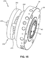
- FIG Fig. 15 Another embodiment of a nozzle arrangement 204 is shown in FIG Fig. 15 shown.
- the nozzle arrangement 204 has a pressure regulating device 226 and a nozzle unit 28.
- the nozzle unit 28 has a nozzle body 38 and a nozzle plate 40 with nozzle holes 42.
- the pressure regulating device has an actuating nut 236. There are preferably several actuating nuts 236 on the pressure regulating device 226, in particular three actuating nuts 236.
- the structure of the pressure regulating device 226 may include the Figures 16-20 can be removed.
- the pressure regulating device 226 has a base body 230 in which a flow channel 246 is formed.
- an annular channel section 250 is formed in an area between the pressure regulating device 226 and the nozzle unit 28.
- the pins 274 protrude into it and can be moved translationally in the direction of the nozzle unit 28 or away from it.
- the pins 274 are guided in sections in the main body 230 and their heads are mounted in a receiving ring 292.
- a translational movement of the mounting ring 292 thus also causes a translational movement of the pins 274.
- the mounting ring 292 is connected to the base body 230 and to the connecting ring 294 by means of one, preferably several, actuating nuts 236.
- a rotation of the actuating nut 236 causes the receiving ring 292, depending on the direction of rotation, to move translationally in the direction of the nozzle unit 28 or away from it. Since the pins 274 are received in the receiving ring 292, they are moved in an analogous translatory manner. Thus, by actuating or rotating the actuating nuts 236, it is possible to move the pins 274 translationally into the annular channel section 250 or into the nozzle body flow channels 60 and to move them out of these.
- the different operating states of the nozzle arrangement 204 are the Figs. 17-18 refer to. The one in the Fig. 17 In the state shown, the pins 274 have been moved away from the nozzle body 38 to the maximum extent.
- the pins 274 thus only extend into the area of the annular channel section 250 and slightly into the nozzle body flow channels 60. A larger free flow cross-section remains in the area of the annular channel section 250 or the nozzle body flow channels 60 Fig. 18 In the state shown, the pins 274 have been moved in a translatory manner at most in the direction of the nozzle body 38. As from the Fig. 18 As can be seen, the remaining free flow cross section, in particular in the nozzle body flow channels 60, is now minimal.
- the Figures 19 and 20 show alternative exemplary embodiments with regard to the design of the pins 296.
- the pins 296 are now lengthened compared to the previous exemplary embodiments. Accordingly, depending on the operating state, the pins 296 extend further, in particular into the nozzle body flow channels 60, as a result of which the free flow cross section and thus indirectly the melt pressure in the immediate vicinity of the nozzle plate 40 can be influenced.
- FIG. 21 A final embodiment of a nozzle assembly 304 is shown.
- the nozzle arrangement 304 is composed of the in the Figs. 2 to 5 pressure regulating device 26 shown with an alternative embodiment of a nozzle unit 328.
- a detailed description of the pressure regulating device 26 is not provided here and reference is made to the above description.
- the alternative The configuration of the nozzle unit 328 is characterized by a nozzle body 338 in which nozzle body flow channels 360 are formed in a known manner.
- a guide cone 358 is arranged on the nozzle body 338, which is arranged on the nozzle body 338 with a cone fastening screw 356.
- a heating ring 398 which is used to heat the nozzle unit 328, is arranged around the nozzle body 338. It becomes clear here that the pressure regulating device 26 can be combined with a multiplicity of nozzle units 328.
- the nozzle unit can be used as a two-part nozzle unit, as in FIG Fig. 21 described, or as a one-piece nozzle unit, as in Figures 1 to 20 described, be formed.
- the nozzle unit can also be heated in many ways, for example by means of electrical current, a heating fluid or steam and the like.
- Fig. 22 shows a nozzle unit 428 and a pressure regulating device 426 arranged on the nozzle unit.
- the pressure regulating device 426 has a fluid inlet side 432 at which fluid can reach the pressure regulating device 426 by means of the flow channel 446.
- the pressure regulating device 426 also has a base body 430 on which a first housing ring 488 and a second housing ring 490 are arranged.
- An inlet / outlet for pressure fluid 484 is arranged in the first housing ring 488.
- a second inlet / outlet for pressurized fluid 486 is arranged on the second housing ring 490.
- Fig. 23 The functional principle is based on the Fig. 23 and Fig. 24 illustrates. How Fig. 23 can be removed, the inlets / outlets for pressure fluid 484, 486 are connected to a cylinder space 496 which is arranged in the second housing ring 490. A piston 494, which is connected to pins 474, is also arranged in the cylinder space 496. A bellows 492 is used to seal the piston 494. If pressure fluid is now introduced into the cylinder space 496 via the inlet / outlet for pressure fluid 486, this has the effect that the piston 494 is shifted to the right in the plane of the drawing.
- pin 474 or the plurality of pins 474 are at least partially retracted into nozzle body flow channels 460.
- the flow cross section in the nozzle body flow channels 460 and in the annular channel section 450 is regulated.
- the nozzle body 438 has a nozzle plate 440 and is connected to a guide cone 458 by means of a cone fastening screw 456 and a centering pin 454.
- FIG. 24 shows an operating state of the pressure regulating device 426 in which the pins 474 are in a compared to FIG Fig. 23 less the ring channel section 450 narrowing state.
- Moving the piston 494 to the left - seen in the plane of the drawing - can in particular take place in that pressurized fluid is introduced via an inlet / outlet for pressurized fluid 484 into the cylinder space 496 on the side of the piston 494 that is inclined towards the bellows 492.
- pressurized fluid can flow out of the inlet / outlet 486, the introduction of pressurized fluid via the inlet / outlet 484 causes the piston 494 to move to the left in the plane of the drawing and the pins 474 coupled to the piston 494 to move to the left and thus are at least partially moved out of the annular channel section 450 and the nozzle body flow channels 460.
- FIG. 25 and FIG. 26 show alternative embodiments of FIG Figures 4 and 5 nozzle arrangement described 4.
- the in the Figures 25 and 26 The embodiment shown differs from that in FIG Figures 4-5 shown in particular by the shape of the control section 52a, which is shown in the Figures 25 and 26 Is concave, as well as by the shape of the nozzle body 38a, which is in the Figures 25 and 26 has a convex design of the flow channel in the area of the annular channel section 50.
- FIG. 27 and FIG. 28 show a further alternative embodiment of a regulating section 52b and nozzle body 28b.
- the regulating section 52b is now convex.
- the nozzle body 38b is correspondingly concave in the region of the regulating section 52b. Otherwise, refer to the description of the figures for the Figures 4-5 referenced.
- the Fig. 29 and FIG. 30 show a further alternative exemplary embodiment of a nozzle unit 528.
- the nozzle unit 528 has a nozzle body 538 which is connected to a further base body 530.
- the base body 530 forms an annular channel section 550.
- the free flow cross section in the annular channel 550 can be influenced by a translational movement of the axially adjustable guide cone 558 relative to the base body 530.
- the axial adjustability of the guide cone 558 is achieved as follows. Of the axially adjustable guide cone 558 is initially guided in a translationally movable manner with respect to the nozzle body 538 by means of a conical guide 592.
- the guide cone 558 is adjusted in a fluidic manner.
- the nozzle body 538 is designed such that it forms a first pressure chamber 580 in conjunction with a pressure chamber ring 590. If pressure fluid is introduced into the first pressure chamber 580, the axially adjustable guide cone 558 is moved to the left in the plane of the drawing in this way.
- a second pressure chamber 582 is formed in the guide cone 558, which is sealed off from a distributor section 854 by means of a sealing ring 586. If pressure fluid is now introduced into the second pressure chamber 582 by means of the inlet / outlet 588, the result is that the axially adjustable guide cone 558 moves to the right as seen in the plane of the drawing and the free flow cross-section in the area of the annular channel section 550 is reduced. In the same way, an introduction of pressurized fluid into the first pressure chamber 580 leads to the axially adjustable guide cone 558 now being displaced to the right as seen in the plane of the drawing. This has the consequence that the free flow cross section in the area of the annular channel section 550 is enlarged.
- the cone 558 has on its side facing the annular channel section 550 a trapezoidal section 596 for influencing the flow cross section in the annular channel section 550.
- FIG Figures 31 and 32 An alternative embodiment of a nozzle unit 528a, which also realizes the basic principle of an axially adjustable guide cone 558a, is shown in FIG Figures 31 and 32 shown.
- a bellows 594 is arranged between the axially adjustable guide cone 558a and the nozzle unit 538a. If the axially adjustable guide cone is located, as in Fig. 31 shown, in an extended state in which the axially adjustable guide cone 558a has been moved to the left in the plane of the drawing, the bellows 594 lies closely against a transition area between the axially adjustable guide cone 558a and the nozzle body 538a. The free flow cross section of the annular channel section 550 is therefore not narrowed by the bellows 594.
- the in Fig. 32 In contrast, the state shown is the axially adjustable guide cone 558a in a retracted state, that is, in a plane opposite to FIG Fig. 31 state moved to the right. If the axially adjustable guide cone 558a is in the relevant state, the bellows 594 experiences a compression, which leads to the fact that it moves into the area of the annular channel section bulges. This in turn causes a reduction in the free flow cross section in the area of the annular channel section 550.
- a further adaptation of the free flow cross section in the area between the base body 530 and the axially adjustable guide cone 558a also takes place through the translational displacement of the guide cone 558a with respect to the base body 530.
- FIG Fig. 33 and 34 An alternative mechanical adjustment device for axially adjusting a guide cone 658 is shown in FIG Fig. 33 and 34 are shown.
- the guide cone 658 is initially guided in an axially adjustable manner in the nozzle body 638.
- the nozzle body 638 also has a bore in the area of its longitudinal axis, into which a threaded pin 696 is let.
- the threaded pin 696 can be actuated from outside the device, in particular from the outside of the nozzle plate 640.
- a nut 698 is attached to the threaded pin 696.
- the axially adjustable guide cone 658 has a bore which is arranged in the region of its longitudinal axis and which in turn has an internal thread into which an external thread applied to the threaded pin 696 can engage.
- Rotability of the axially adjustable guide cone 658 is inhibited by a centering pin 654, so that a rotation of the threaded pin 696 has the consequence that the axially adjustable guide cone experiences a translational movement in the axial direction as a function of the direction of rotation.
- the flow cross section between the guide cone 658 and the base body 630 is influenced.
- Fig. 35 and 36 show a further exemplary embodiment in which a mechanical axial adjustment of a guide cone 758 is also carried out.
- the adjustment element in question or the adjustment pin 796 is no longer guided in the area of a nozzle plate 740, but radially outward from a nozzle body 738 to the outside.
- the valve pin 796 is arranged in a radial recess in the nozzle body 738.
- the adjusting pin 796 On its inwardly directed side, has a gear section 782 in combination with a rotary body 798.
- a rotary movement of the valve pin 796 is transmitted to the rotary body 798 by means of the gear section 782 in such a way that the latter can now be rotated about an axis of rotation which essentially corresponds to the longitudinal axis of the nozzle body 738.
- the rotary body 798 is guided by means of a ball bearing 786. Furthermore, the position of the rotary body 798 on a receiving section 784 of the nozzle body 738 is fixed by a locking ring 788.
- the change in the position of the axially adjustable guide cone 758 in turn causes a change in the flow cross section between the base body 730 and the axially adjustable guide cone 758.
- FIG Fig. 37 and 38 Another alternative embodiment of a fluidically axially adjustable guide cone 858 is shown in FIG Fig. 37 and 38 are shown.
- the axially adjustable guide cone 858 is axially movably supported in a nozzle body 838 and can be axially adjusted by means of fluid which can be introduced into a first pressure chamber 880 and a second pressure chamber 882.
- An axial adjustment of the guide cone 858 causes a change in the flow channel between a base body 830 and the axially adjustable guide cone 858.
- the axial adjustment of the guide cone 858 does not change the free flow cross section in the annular channel section 850.
- Fig. 39 shows a nozzle unit 928 which has a nozzle body 938 in which throttle pins 996 extend radially inward.
- a guide cone 958 is arranged on the nozzle body 938.
- the Fig. 40 and FIG. 41 show sectional views relating to a region of the nozzle body 938.
- nozzle body flow channels 960 extend through the nozzle body 938. These guide fluid from a flow channel 960 arranged adjacent to the guide cone 958 to the nozzle plate 940.
- throttle pins 996 are arranged in the nozzle body 938.
- throttle pins 996 can be actuated from outside the nozzle body 938 and limit the free flow cross section of the nozzle body flow channels 960 as a function of how far the throttle pins 996 are introduced into the nozzle body flow channels 960.
- the throttle pin 996 In the in the Fig. 40 In the state shown, the throttle pin 996 only partially delimits the nozzle body flow channel 960. The one in the Fig. 41 In the state shown, the throttle pin 996 is pushed almost completely into the nozzle body flow channel 960 and limits it almost completely.
- FIG Fig. 42 Another alternative embodiment of a nozzle unit 1028 is shown in FIG Fig. 42 shown.
- the nozzle unit 1028 again has a nozzle body 1038, in which slide rods 1096 are introduced. Furthermore, a guide cone 1058 is arranged on the nozzle body 1038.
- the functionality of the nozzle unit 1028 can be the Fig. 43-45 remove.
- the slide rods 1096 are coupled to slide elements 1098.
- These slide elements 1098 have slide bores 1084 and are arranged movably within a slide chamber 1082. In the in Fig. 43 In the operating state shown, the slide bores 1084 are arranged in overlap with nozzle body flow channels 1060. The slide elements 1098 therefore do not influence the free flow cross section of the nozzle body flow channels 1060, or only influence them slightly.
- FIGS Fig. 46-50 Another alternative embodiment is shown in FIGS Fig. 46-50 shown.
- a nozzle unit 1128 has a pressure regulating device 1126.
- the nozzle unit 1128 has a base body 1130. Adjusting screws 1196 are inserted into the pressure regulating device 1126.
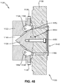
- the Fig. 47 and 48 show sectional views of the nozzle unit 1128 in different operating states.
- the nozzle body 1138 has nozzle body flow channels 1160.
- a guide cone 1158 is connected to the nozzle body 1138. The connection is made by means of a centering pin 1154 and a cone fastening screw 1156.
- the pressure regulating device 1126 is coupled to the nozzle body 1138 and has a base body 1130 in which, together with the guide cone 1158, the nozzle unit 1128 a flow channel 1146 forms.
- throttle elements 1198 are arranged in the area of this flow channel 1146 between the base body 1130 and the guide cone 1158.
- the throttle elements 1198 are rotatably arranged on an axis of rotation 1194.
- an adjusting screw 1196 which acts on the throttle element 1198, the throttle element 1198 can be pivoted into the area of the flow channel 1146 between the guide cone 1158 and the base body 1130, whereby the free flow cross-section in this area depending on the position of the Throttle element 1198 is limited.
- the one in the Fig. 47 As shown in the state of the throttle element 1198, the flow channel 1146 is not limited or only very slightly limited.
- the Figures 51 and 52 show an alternative embodiment of a nozzle unit 1228.
- the nozzle unit 1228 has a nozzle body 1238.
- a slide adjusting device 1296 is arranged around a longitudinal axis of the nozzle body 1238.
- the slide adjusting device 1296 is rotatably mounted.
- Slide elements 1298 which each have slide bores 1284, are coupled to slide adjustment device 1296.
- the slide bores 1284 of the slide adjustment device 1296 are arranged in overlap and therefore in alignment with the nozzle body flow channels 1260.
- the operating state shown does not significantly affect the nozzle body flow channels 1260.
- the slide elements 1298 are not arranged in alignment with respect to the nozzle body flow channels 1260.
- the positioning of the slide elements 1298 in the present case delimits the nozzle body flow channels 1260 and reduces the existing free flow cross section.
- the free flow cross section can be regulated.
- FIGS Figures 53-56 Another alternative embodiment of a nozzle unit 1328 is shown in FIGS Figures 53-56 shown.
- Fig. 53 shows first a nozzle unit 1328 with a nozzle body 1338.
- a nozzle plate 1340 which has nozzle holes 1342, is arranged on the nozzle body 1338.
- An adjusting head 1380 is also arranged in the area of the nozzle plate 1340.
- the nozzle unit 1328 has a nozzle body 1338 in which nozzle body flow channels 1360 are arranged.
- a guide cone 1358 is arranged on the nozzle body 1338.
- An adjusting element 1384 is also arranged in the region of a longitudinal axis of the nozzle body 1338.
- the adjusting element 1384 has an adjusting head 1380 on a first side.
- An adjusting disk 1382 is arranged on the adjusting element 1384.
- the adjusting disk 1382 has adjusting disk bores 1386.
- the diameter of the adjusting disk bores 1346 corresponds approximately to the diameter of the nozzle body flow channels 1360.
- the free flow cross section in the area of the nozzle body flow channels 1360 can be varied .
- nozzle body flow channels 1360 are aligned with the adjusting disk bores 1386, there is no substantial restriction or limitation of a fluid flow through the nozzle body flow channels 1360. However, if the adjusting head 1380 rotates the adjusting disk 1382 from the position shown in FIG Fig. 54 position shown in such a way that the adjusting disk bore 1386 is no longer aligned with the nozzle body flow channels 1360, the flow conditions in the nozzle body flow channels 1360 are then limited.
- FIG. Fig. 57 An alternative embodiment of a nozzle unit 1428 is shown in FIG Fig. 57 shown.
- the nozzle unit 1428 has an adjusting disk 1482 which is mounted so as to be movable relative to a nozzle body 1438.
- the adjusting disk 1482 has adjusting disk bores 1490, which are positioned relative to the nozzle body flow channels 1460 in alignment can be so that a limitation of a fluid flow through the nozzle body flow channels 1460 is virtually no, or, as in Fig. 57 shown, can be brought into a non-aligned position with respect to these in order to limit the flow of fluid through the nozzle body flow channels 1460.
- the adjustment disk 1482 has a threaded section 1484.
- An adjusting element 1486 arranged in the nozzle body 1438 has a screw 1488 in the region of one of its ends.
- the worm 1488 corresponds to the threaded section 1484 in such a way that a rotation of the adjusting element 1486 with the worm 1488 causes the adjusting disk 1482 to rotate.
- the adjusting element 1486 is guided in such a way that one of its ends can be actuated from outside the nozzle body 1438.
- Fig. 58 shows a control block diagram 1500 for controlling a pressure regulating device 1510.
- the arrangement has a pressure sensor 1502, which is connected to a controller 1506 in a signal-conducting manner.
- the controller 1506 activates an actuator 1508, which in turn controls a pressure regulating device 1510 depending on the pressure value measured with the pressure sensor 1502.
- the controller 1506 the pressure in a plastic melt flow 1504 in the area of a nozzle plate 1540 can be influenced in the desired manner and by means of the technical devices mentioned and described in the exemplary embodiments.
Abstract
Düsenanordnung für eine Granuliervorrichtung (2), mit einer Druckreguliervorrichtung (26), umfassend einen Grundkörper (30) mit einer Fluid-Eintrittsseite (32) sowie einer Fluid-Austrittsseite (48), einen in dem Grundkörper ausgebildeten Strömungskanal (46) zur fluidleitenden Verbindung der Fluid-Eintrittsseite mit der Fluid-Austrittsseite, und einen mit dem Strömungskanal fluidleitend verbundenen und im Bereich der Fluid-Austrittsseite ausgebildeten Ringkanalabschnitt (50), wobei die Druckreguliervorrichtung ein relativ zu dem Ringkanalabschnitt und/oder dem Strömungskanal bewegbares Strömungsquerschnittsregulierelement in Form eines Regulierrings (186) zur Beeinflussung des Strömungsquerschnitts des Ringkanalabschnitts aufweist. Ebenfalls beansprucht wird ein darauf bezogenes Verfahren.Nozzle arrangement for a granulating device (2), with a pressure regulating device (26), comprising a base body (30) with a fluid inlet side (32) and a fluid outlet side (48), a flow channel (46) formed in the base body for fluid-conducting connection the fluid inlet side with the fluid outlet side, and an annular channel section (50) connected to the flow channel in a fluid-conducting manner and formed in the area of the fluid outlet side, the pressure regulating device being a flow cross-section regulating element in the form of a regulating ring ( 186) for influencing the flow cross-section of the annular channel section. A related method is also claimed.
Description
Die Erfindung betrifft eine Düsenanordnung für eine Granuliervorrichtung, mit einer mit dem Düsenkörper gekoppelten Druckreguliervorrichtung, umfassend einen Grundkörper mit einer Fluid-Eintrittsseite sowie einer Fluid-Austrittsseite, einen in dem Grundkörper ausgebildeten Strömungskanal zur fluidleitenden Verbindung der Fluid-Eintrittsseite mit der Fluid-Austrittsseite sowie einen mit dem Strömungskanal fluidleitend verbundenen und im Bereich der Fluid-Austrittsseite ausgebildeten Ringkanalabschnitt.The invention relates to a nozzle arrangement for a granulating device, with a pressure regulating device coupled to the nozzle body, comprising a base body with a fluid inlet side and a fluid outlet side, a flow channel formed in the base body for the fluid-conducting connection of the fluid inlet side with the fluid outlet side and an annular channel section connected to the flow channel in a fluid-conducting manner and formed in the region of the fluid outlet side.
Derartige Düsenanordnungen sind im Stand der Technik bekannt und finden beispielsweise bei Granuliervorrichtungen Verwendung. Sie werden dazu eingesetzt, geschmolzenes Granuliermaterial, wie beispielsweise thermoplastische Kunststoffe, mittels einer Düsenplatte in die Form von zumeist mehreren Schmelzesträngen zu extrudieren. Im Rahmen des Verfahrens der sogenannten Unterwassergranulierung werden die einzelnen Schmelzestränge anschließend mittels einer Schneidvorrichtung in Strangabschnitte unterteilt, welche, wenn sie mit einem Kühlfluid, beispielsweise Wasser, in Kontakt treten, abgekühlt werden und somit Granulatkörner bilden. Das Verfahren der Unterwassergranulierung ermöglicht einen hohen Granulierungsmaterialdurchsatz bei geringem erforderlichem Bauraum einer solchen Vorrichtung und bei geringen Emissionen in Form von Staub oder Lärm.Such nozzle arrangements are known in the prior art and are used, for example, in granulating devices. They are used to extrude molten granulating material, such as thermoplastics, by means of a nozzle plate in the form of mostly several strands of melt. As part of the so-called underwater granulation process, the individual melt strands are then divided into strand sections by means of a cutting device, which, when they come into contact with a cooling fluid, for example water, are cooled and thus form granules. The underwater granulation process enables a high throughput of granulation material with little space required for such a device and with low emissions in the form of dust or noise.
Bei den im Stand der Technik vorbekannten Düsenanordnungen wird Schmelze an einer Eintrittsseite in einen Düsenkörper geleitet. Mittels einer Vielzahl von Strömungskanälen wird die Schmelze durch den Düsenkörper geführt und gelangt zu einer Düsenplatte. Die Düsenplatte weist typischerweise eine Vielzahl von Düsenlöchern auf, um eine hohe Produktivität und, in Abhängigkeit von der zu verarbeitenden Schmelze, ein gewünschtes Granulierergebnis - das heißt hohe Durchsätze bzw. kleine Granulatkörner - zu erzielen. Hierbei ergibt sich bei klassischen, aus dem Stand der Technik vorbekannten Düsenanordnungen der Nachteil, dass insbesondere die Düsenkörper sowie die Düsenplatten jeweils für bestimmte Durchsätze und Viskositäten von Kunststoffschmelzen ausgelegt sind. So ist jedes Material, bzw. jede Schmelze typischerweise mit vorteilhaften Prozessparametern, wie beispielsweise einem vorgegebenen Verarbeitungsdruck zu verarbeiten, um sicherzustellen, dass die Schmelzestränge auf eine gewünschte Weise aus der Düsenplatte austreten. Bei aus dem Stand der Technik vorbekannten Düsenanordnungen führen Materialwechsel typischerweise dazu, dass die vollständige Düsenanordnung ausgetauscht wird und für jedes zu verarbeitende Material oder zumindest für Materialgruppen unterschiedlicher Düsenanordnungen bereitzuhalten sind. Sollen unterschiedliche Materialien verarbeitet werden, so ergibt sich hierdurch eine hohe Kapitalbindung, da eine Vielzahl von Düsenanordnungen vorgehalten werden müssen. Darüber hinaus gestaltet sich der Austausch einer Düsenanordnung typischerweise zeitaufwendig wodurch insgesamt ein Wechsel des zu verarbeitenden Materials mit hohen Rüstkosten einhergeht.In the nozzle arrangements known in the prior art, melt is fed into a nozzle body on an inlet side. The melt is guided through the nozzle body by means of a large number of flow channels and reaches a nozzle plate. The nozzle plate typically has a large number of nozzle holes in order to achieve high productivity and, depending on the melt to be processed, a desired granulation result - that is, high throughputs or small granules. In the case of classic nozzle arrangements known from the prior art, this has the disadvantage that, in particular, the nozzle bodies and the nozzle plates are each designed for specific throughputs and viscosities of plastic melts. Each material or each melt is typically to be processed with advantageous process parameters, such as a predetermined processing pressure, in order to ensure that the melt strands emerge from the nozzle plate in a desired manner. In the case of nozzle arrangements known from the prior art, material changes typically result in the complete nozzle arrangement being exchanged and having to be kept ready for each material to be processed or at least for material groups of different nozzle arrangements. If different materials are to be processed, this results in a high capital commitment, since a large number of nozzle arrangements have to be kept available. In addition, replacing a nozzle arrangement is typically time-consuming, which means that changing the material to be processed is associated with high set-up costs.
Um die Verarbeitung unterschiedlicher Materialien mit unterschiedlichen Viskositäten mit einer einzigen Düsenanordnung zu ermöglichen, ist aus dem Stand der Technik die Verwendung von Druckreguliervorrichtungen bekannt. Beispielsweise betrifft die
Allerdings bringt eine solche Lösung den Nachteil mit sich, dass die Herstellungs- und Wartungskosten einer solchen Anordnung aufgrund der hohen Komplexität gegenüber den aus dem Stand der Technik vorbekannten klassischen Düsenanordnungen signifikant steigen. Zwar lässt sich mit einer solchen Vorrichtung verhindern, dass eine Vielzahl von Düsenanordnungen zur Verarbeitung unterschiedlicher Materialien mit unterschiedlichen Viskositäten bereitgehalten werden müssen, der sich hierdurch potenziell ergebende Kostenvorteil lässt sich aufgrund der hohen Komplexität der vorgeschlagenen Vorrichtung jedoch nicht bestmöglich ausschöpfen.However, such a solution has the disadvantage that the production and maintenance costs of such an arrangement due to the high complexity compared to the conventional nozzle arrangements known from the prior art increase significantly. Although it is possible with such a device to prevent a large number of nozzle arrangements for processing different materials with different viscosities from having to be kept ready, the potential cost advantage that results from this cannot be optimally exploited due to the high complexity of the proposed device.
Vor diesem Hintergrund lag der Erfindung die Aufgabe zugrunde, eine Düsenanordnung der eingangs bezeichneten Art dahingehend weiterzubilden, dass die im Stand der Technik aufgefundenen Nachteile möglichst weitgehend behoben werden. Insbesondere war eine Düsenanordnung anzugeben, welche für eine Vielzahl von unterschiedlichen Materialien, Materialdurchsätzen und Viskositäten verwendbar ist und gleichzeitig kostengünstig herstellbar ist sowie funktionssicher und leicht wartbar ist.Against this background, the invention was based on the object of developing a nozzle arrangement of the type described at the outset in such a way that the disadvantages found in the prior art are eliminated as far as possible. In particular, a nozzle arrangement was to be specified which can be used for a large number of different materials, material throughputs and viscosities and at the same time can be produced inexpensively and is functionally reliable and easy to maintain.
Erfindungsgemäß wird die Aufgabe bei einer Düsenanordnung der eingangs genannten Art durch ein relativ zu dem Ringkanalabschnitt und/oder dem Strömungskanal bewegbares Strömungsquerschnitts-Regulierelement zur Beeinflussung eines Strömungsquerschnitts des Ringkanalabschnitts gelöst.According to the invention, the object is achieved in a nozzle arrangement of the type mentioned by a flow cross-section regulating element movable relative to the annular channel section and / or the flow channel for influencing a flow cross-section of the annular channel section.
Die Erfindung macht sich die Erkenntnis zunutze, dass die Bewegung eines einzelnen Bauteils, bzw. einer hinsichtlich seiner Bauteilanzahl eng begrenzten Baugruppe dazu verwendet werden kann, den freien Strömungsquerschnitt eines betreffenden Ringkanalabschnitts einer Düsenanordnung so zielführend zu verändern, dass mit einer solchen Düsenanordnungen unterschiedliche Materialien mit unterschiedlichen Durchsätzen und Viskositäten verarbeitet werden können.The invention makes use of the knowledge that the movement of an individual component or of a subassembly, which is narrowly limited in terms of its number of components, can be used to change the free flow cross-section of a relevant annular channel section of a nozzle arrangement in such a way that different materials are involved with such a nozzle arrangement different throughputs and viscosities can be processed.
Ein solches Strömungsquerschnitts-Regulierelement kann dabei insbesondere dazu verwendet werden, den freien Strömungsquerschnitt in einem Ringkanalabschnitt, welcher beispielsweise eine Vielzahl von Strömungskanälen mit Schmelze versorgt, zu beeinflussen. Alternativ oder zusätzlich kann das Strömungsquerschnitts-Regulierelement relativ zu einem Strömungskanal bewegbar sein. Somit kann ein einzelnes Strömungsquerschnitts-Regulierelement dazu eingesetzt werden, mittelbar den Schmelzedruck in einer gesamten Düsenanordnung zu beeinflussen. Die Beeinflussung des freien Strömungsquerschnittes und des Schmelzedruckes erfolgt darüber hinaus in unmittelbare Nähe zu der Düsenplatte, aus welcher die Schmelzestränge austreten. Somit kann insgesamt der Schmelzedruck sehr genau justiert werden, wobei gleichzeitig die Bauteilkomplexität der erfindungsgemäßen Vorrichtung gering ist und diese gleichsam einfach zu warten ist. Gegenüber aus dem Stand der Technik vorbekannten Druckreguliervorrichtungen lässt sich die Kosteneffizienz mittels der erfindungsgemäßen Druckregelvorrichtung deutlich steigern.Such a flow cross section regulating element can in particular be used to influence the free flow cross section in an annular channel section which, for example, supplies a large number of flow channels with melt. Alternatively or additionally, the flow cross-section regulating element can be movable relative to a flow channel. A single flow cross-section regulating element can thus be used to indirectly influence the melt pressure in an entire nozzle arrangement. The free flow cross-section and the melt pressure are also influenced in the immediate vicinity of the nozzle plate from which the melt strands emerge. Thus, overall the melt pressure can be adjusted very precisely, while at the same time the component complexity of the device according to the invention is low and it is easy to maintain. Compared to previously known from the prior art Pressure regulating devices, the cost efficiency can be increased significantly by means of the pressure regulating device according to the invention.
Die Erfindung wird dadurch weitergebildet, dass das Regulierelement in dem Ringkanalabschnitt angeordnet ist. Vorzugsweise wird das Regulierelement dabei von Schmelze umflossen. Das Regulierelement kann nun dazu eingesetzt werden, den Spalt zwischen dem Regulierelement und dem Ringkanalabschnitt und somit den freien Strömungsquerschnitt durch Bewegung des Regulierelements relativ zu dem Ringkanalabschnitt zu beeinflussen. Hierdurch ergibt sich der Vorteil, dass der freie Strömungsquerschnitt und somit mittelbar die Druckverhältnisse in der Schmelze sehr fein dosiert beeinflussbar sind. Auch stellt eine derartige Anordnung sicher, dass der Schmelzefluss möglichst geringfügig beeinträchtigt wird, insbesondere eine starke Wirbelbildung sicher verhindert wird.The invention is further developed in that the regulating element is arranged in the annular channel section. The regulating element is preferably surrounded by melt. The regulating element can now be used to influence the gap between the regulating element and the annular channel section and thus the free flow cross section by moving the regulating element relative to the annular channel section. This results in the advantage that the free flow cross section and thus indirectly the pressure conditions in the melt can be influenced in a very finely dosed manner. Such an arrangement also ensures that the melt flow is impaired as little as possible, in particular that strong vortex formation is reliably prevented.
Gemäß einer bevorzugten Ausführungsform weist das Regulierelement einen Regulierring sowie einen mit dem Regulierring verbundenen Haltering auf. Ein solcher zweistückiger Aufbau ermöglicht eine einfache Austauschbarkeit des Regulierrings und einer bedarfsweisen Anpassung desselben an beispielsweise unterschiedliche Materialien, Durchsätze oder Viskositäten. Auch ist im Verschleißfalle ein einfacher Austausch der Einzelkomponenten gewährleistet. Regulierring und Haltering können dabei auf vielfache Weise verbunden sein. Infrage kommt beispielsweise eine Schraubverbindung, eine hitzebeständige Klebeverbindung oder auch eine formschlüssige Verbindung.According to a preferred embodiment, the regulating element has a regulating ring and a retaining ring connected to the regulating ring. Such a two-piece structure enables the regulating ring to be easily exchanged and to be adapted as required to, for example, different materials, throughputs or viscosities. Simple replacement of the individual components is also guaranteed in the event of wear. Regulating ring and retaining ring can be connected in many ways. For example, a screw connection, a heat-resistant adhesive connection or a form-fitting connection are possible.
Die Erfindung wird dadurch weitergebildet, dass der Regulierring keilförmig ausgebildet ist. Eine Keilform des Regulierrings hat sich dabei als besonders günstig zur Beeinflussung des freien Strömungsquerschnitts erwiesen, ohne den Schmelzestrom beispielsweise durch Wirbelbildung nachteilig zu beeinflussen. Gemäß einer alternativen Ausführungsform kann der Regulierring konkave und/oder konvexe Abschnitte zur zielgerichteten Strömungsbeeinflussung aufweisen oder auf andere Weise strömungsgünstig ausgebildet sein.The invention is further developed in that the regulating ring is wedge-shaped. A wedge shape of the regulating ring has proven to be particularly favorable for influencing the free flow cross section without adversely affecting the melt flow, for example through the formation of eddies. According to an alternative embodiment, the regulating ring can have concave and / or convex sections for targeted influencing of the flow or it can be designed in a flow-favorable manner in some other way.
Gemäß einer bevorzugten Weiterbildung weist der Regulierring Stifte auf, welche sich in Abhängigkeit von der Position des Regulierrings zumindest abschnittsweise in den Ringkanalabschnitt erstrecken. Die zusätzliche Verwendung solcher Stifte, auch als Druckregulierstifte bezeichnet, ermöglicht eine zusätzliche bereichsweise Einschränkung des freien Strömungsquerschnitts, sodass sich der Druck der Schmelze mittels solcher Stifte zusätzlich beeinflussen lässt. Alternativ oder zusätzlich können die Stifte so dimensioniert sein, dass sie insbesondere in die in dem Düsenkörper ausgebildeten Strömungskanäle hineinreichen. Hierdurch lässt sich das Gebiet der Druckbeeinflussung näher in Richtung der Düsenscheibe verlagern. Je nach verwendetem Schmelze- bzw. je nach gewünschtem Materialdurchsatz lässt sich die Qualität der Schmelzestränge hiermit positiv beeinflussen.According to a preferred development, the regulating ring has pins which, depending on the position of the regulating ring, extend at least in sections into the annular channel section. The additional use of such pins, also referred to as pressure regulating pins, enables an additional restriction of the free flow cross-section in certain areas, so that the pressure of the melt is increased by means of such pins Pens can also influence. Alternatively or additionally, the pins can be dimensioned in such a way that they in particular extend into the flow channels formed in the nozzle body. In this way, the area of the pressure influencing can be shifted closer in the direction of the nozzle disk. Depending on the melt used or the desired material throughput, the quality of the melt strands can be positively influenced.
Weiterhin bevorzugt verfügt die Düsenanordnung über mindestens einen mit dem Regulierelement verbundenen Aktuator zur Bewegung des Regulierelements relativ zu dem Ringkanalabschnitt, insbesondere in einer translatorischen Richtung entlang einer Grundkörperlängsachse. Hierbei weist die Düsenanordnung bevorzugt drei oder mehr solcher Aktuatoren auf, um sicherzustellen, dass das Regulierelement im Bereich des Ringkanals einen über den Ringkanalverlauf möglichst konstanten Abstand zu den seitlichen Begrenzungen des Ringkanals aufweist. Insbesondere ist jedenfalls sicherzustellen, dass ein Verkanten des Regulierelements verhindert wird und somit mittelbar ein ungleichmäßiger Schmelzeaustritt aus der Düsenplatte.Furthermore, the nozzle arrangement preferably has at least one actuator connected to the regulating element for moving the regulating element relative to the annular channel section, in particular in a translational direction along a longitudinal axis of the base body. In this case, the nozzle arrangement preferably has three or more such actuators in order to ensure that the regulating element in the area of the ring channel has a distance from the lateral boundaries of the ring channel that is as constant as possible over the course of the ring channel. In particular, it must be ensured in any case that tilting of the regulating element is prevented and thus indirectly an uneven melt discharge from the nozzle plate.
Gemäß einer alternativen Ausführungsform ist der Aktuator als fluidbetätigter Aktuator ausgebildet, insbesondere als pneumatischer Aktuator oder hydraulischer Aktuator. Die Ausbildung des Aktuators als fluidbetätigter Aktuator hat sich als vorzugswürdig für Anwendungen gezeigt, bei denen die Anzahl mechanischer Bauteile reduziert werden soll und gleichzeitig ein verschleißarmer Aktuator verwendet werden soll.According to an alternative embodiment, the actuator is designed as a fluid-operated actuator, in particular as a pneumatic actuator or hydraulic actuator. The design of the actuator as a fluid-operated actuator has proven to be preferable for applications in which the number of mechanical components is to be reduced and at the same time a low-wear actuator is to be used.
Vorzugsweise weist der fluidbetätigte Aktuator einen Zylinder mit mindestens einem Druckfluidein-/auslass auf, wobei der Zylinder und der mindestens eine Druckfluidein-/auslass in dem Grundkörper ausgebildet sind. Durch die Ausbildung des Zylinders in dem Grundkörper lässt sich die Anzahl der erforderlichen Bauteile weiter reduzieren. Vorzugsweise ist in dem Zylinder ein Kolben angeordnet, der mittels eines Faltenbalges gegenüber dem Zylinder abgedichtet ist. Eine haltbare und sichere Dichtung kann hiermit gewährleistet werden.The fluid-actuated actuator preferably has a cylinder with at least one pressure fluid inlet / outlet, the cylinder and the at least one pressure fluid inlet / outlet being formed in the base body. The number of components required can be further reduced by designing the cylinder in the base body. A piston, which is sealed off from the cylinder by means of a bellows, is preferably arranged in the cylinder. This ensures a durable and secure seal.
Der Aktuator ist vorzugsweise so ausgebildet, dass dieser einen mit dem Haltering verbundenen Zapfen aufweist, welcher mit einem translatorisch bewegbaren Stößel wirkverbunden ist. Die beschriebene Anordnung ermöglicht eine feinfühlige Einstellung der Position des Halterings bzw. des Regulierelements bei gleichzeitig konstruktiv einfachem Aufbau.The actuator is preferably designed such that it has a pin which is connected to the retaining ring and which is operatively connected to a translationally movable plunger. The arrangement described enables the position of the retaining ring or the regulating element to be set sensitively while at the same time being structurally simple.
Ferner ist bevorzugt, dass der Grundkörper mindestens eine Lagerungsbohrung zur Lagerung des Stößels und zur Führung des Stößels zu einer Außenseite des Grundkörpers aufweist. Diese Lagerungsbohrung weist bevorzugt eine Dichtung zur Verhinderung eines Schmelzeaustrittes aus dem Gehäuse auf. Weiterhin ist bevorzugt, dass der Stößel ein Betätigungselement aufweist, insbesondere eine außerhalb des Gehäuses angeordnet Mutter oder ein Zahnrad, welche bevorzugt mit einem Außengewinde des Stößels korrespondieren. Ein solches außerhalb des Gehäuses angeordnete Betätigungselement ermöglicht auf einfache Weise eine Betätigung des Regulierelements und es wird sichergestellt, dass Schmelze nicht aus dem Gehäuse austreten kann. Die Art des Betätigungselements kann dabei insgesamt flexibel gewählt werden und richtet sich insbesondere danach, wie selbiges angesteuert werden soll. Beispielsweise kann das Betätigungselement Vorrichtungen zur Handbetätigung aufweisen, oder Maschinenelemente wie Muttern oder Zahnräder.It is further preferred that the base body has at least one bearing bore for mounting the plunger and for guiding the plunger to an outside of the base body. This bearing bore preferably has a seal to prevent melt from escaping from the housing. It is also preferred that the tappet has an actuating element, in particular a nut or a gear arranged outside the housing, which preferably corresponds to an external thread of the tappet. Such an actuating element arranged outside the housing enables the regulating element to be actuated in a simple manner and it is ensured that melt cannot escape from the housing. The type of actuating element can be selected flexibly overall and depends in particular on how it is to be controlled. For example, the actuating element can have devices for manual actuation, or machine elements such as nuts or gears.
Die Erfindung wird durch eine Kopplungseinrichtung zur Kopplung der Betätigungselemente von mindestens zwei Aktuatoren weitergebildet. Dabei ist die Kopplungseinrichtung bevorzugt als Hohlrad ausgebildet, welches mit den Betätigungselementen, insbesondere den Zahnrädern, der mehreren Betätigungselemente in Eingriff steht, sodass eine Betätigung des Hohlrades eine Betätigung der mehreren Betätigungselemente bewirkt. Diesem liegt das Prinzip zugrunde, dass die Betätigung einer einzelnen Kopplungseinrichtung mehrere Aktuatoren einer Düsenanordnung insbesondere synchron betätigt. In alternativen Ausführungsbeispielen können die Aktuatoren selbst oder eine Gruppe von Aktuatoren, die auf beliebige Weise gekoppelt sein können, mittels eines motorischen Antriebes, eines Pneumatikantriebes, eines Elektroantriebes, oder eines Linearantriebes einzeln oder in Gruppen betätigt werden.The invention is further developed by a coupling device for coupling the actuating elements of at least two actuators. The coupling device is preferably designed as a ring gear which is in engagement with the actuating elements, in particular the gearwheels, of the plurality of actuating elements, so that actuation of the ring gear causes actuation of the plurality of actuating elements. This is based on the principle that the actuation of a single coupling device actuates several actuators of a nozzle arrangement, in particular synchronously. In alternative exemplary embodiments, the actuators themselves or a group of actuators, which can be coupled in any way, can be operated individually or in groups by means of a motor drive, a pneumatic drive, an electric drive, or a linear drive.
Gemäß einer bevorzugten Ausführungsform weisen die Betätigungselemente oder die Kopplungseinrichtung einen Antrieb und/oder einen Handhebel auf. Als Antrieb kommt hierbei insbesondere ein Elektromotor, ein pneumatischer Antrieb, oder ein Linearantrieb infrage. Ein Handhebel stellt dabei eine besonders kostengünstige Betätigungsmöglichkeit bereit, die jedoch eine unmittelbare Interaktion eines Bedieners erfordert. Eine Betätigung der Kopplungseinrichtung mittels eines Antriebes ermöglicht es, die Düsenanordnung bezüglich der Betätigung des Regulierelementes zu automatisieren.According to a preferred embodiment, the actuating elements or the coupling device have a drive and / or a hand lever. In particular, an electric motor, a pneumatic drive, or a linear drive can be used as the drive. A hand lever provides a particularly inexpensive means of actuation, which, however, requires direct interaction by an operator. Actuation of the coupling device by means of a drive makes it possible to automate the nozzle arrangement with regard to the actuation of the regulating element.
Gemäß einer alternativen Ausführungsform ist das Regulierelement als Hülse ausgebildet, wobei die Hülse den Grundkörper zumindest abschnittsweise umgibt und translatorisch in Richtung der Grundkörperlängsachse bewegbar ist, wobei an dem Regulierelement ein Regelabschnitt ausgebildet ist, welcher dazu eingerichtet ist, den freien Strömungsquerschnitt in dem Ringkanalabschnitt zu beeinflussen. Die Ausgestaltung des Regulierelements als Hülse, bzw. hülsenförmiger Körper hat sich dabei ebenfalls als geeignet zur zielgerichteten Beeinflussung des freien Strömungsquerschnitts in dem Ringkanalabschnitt gezeigt. Diese alternative Ausführungsform geht mit einer weiter reduzierten Bauteilanzahl einher und aufgrund der strukturellen Ausbildung des Regulierelements als Hülse lassen sich insgesamt große Kräfte auf den Regelabschnitt des Regulierelements aufbringen.According to an alternative embodiment, the regulating element is designed as a sleeve, the sleeve surrounding the main body at least in sections and being translationally movable in the direction of the longitudinal axis of the main body, a regulating section being formed on the regulating element which is designed to influence the free flow cross-section in the annular channel section . The design of the regulating element as a sleeve or sleeve-shaped body has also been shown to be suitable for targeted influencing of the free flow cross-section in the annular channel section. This alternative embodiment is accompanied by a further reduced number of components, and due to the structural design of the regulating element as a sleeve, large forces can be applied to the regulating section of the regulating element.
In einer bevorzugten Ausführungsform erfolgt die translatorische Verschiebung der Hülse mittels einer in den Grundkörper eingebrachten Schraube. Die Hülse weist eine korrespondierende Schraubenaufnahme auf, wobei die Aufnahme eine Ausnehmung zum Einbringen einer Betätigungsmutter aufweist, welche auf die Schraube aufschraubbar ist. Die Betätigungsmutter wird in beide Betätigungsrichtungen der Hülse begrenzt, sodass eine Drehung der Mutter bewirkt, dass sich die Hülse translatorisch in Richtung der Grundkörperlängsachse und in die betreffende Gegenrichtung bewegen lässt. Vorzugsweise sind dabei mindestens drei solcher Betätigungsschrauben in dem Grundkörper angeordnet.In a preferred embodiment, the translational displacement of the sleeve takes place by means of a screw introduced into the base body. The sleeve has a corresponding screw receptacle, the receptacle having a recess for inserting an actuating nut which can be screwed onto the screw. The actuating nut is limited in both actuating directions of the sleeve, so that a rotation of the nut causes the sleeve to be moved in a translatory manner in the direction of the longitudinal axis of the main body and in the relevant opposite direction. At least three such actuation screws are preferably arranged in the base body.
Vorzugsweise ist der Regelabschnitt keilförmig ausgebildet. In alternativen Ausführungsformen kann der Regelabschnitt jedoch auch konkave oder konvexe Abschnitte sowie eine Kombination derselben mit geraden Abschnitten aufweisen. Insbesondere kann die Form des Regelabschnittes auf das zu verarbeitende Material, dessen Viskosität und den gewünschten Durchsatz angepasst werden.The regulating section is preferably designed in a wedge shape. In alternative embodiments, however, the regulating section can also have concave or convex sections and a combination thereof with straight sections. In particular, the shape of the control section can be adapted to the material to be processed, its viscosity and the desired throughput.
Ferner weist der Regelabschnitt gemäß einer bevorzugten Ausführungsform Stifte auf, welche sich in Abhängigkeit von der Position des Regelabschnittes relativ zu dem Ringkanalabschnitt zumindest abschnittsweise in den Ringkanalabschnitt erstrecken. In einer weiteren alternativen Ausführungsform weist das Regulierelement Stifte auf, welche sich in Abhängigkeit von der Position des Regulierelements zumindest abschnittsweise in den Ringkanalabschnitt erstrecken. Wie bereits ausgeführt, ermöglichen die Stifte eine weitere Verengung des freien Strömungsquerschnitts und damit mittelbar eine auf einen bestimmten Bereich bezogene Druckerhöhung der Schmelze.Furthermore, according to a preferred embodiment, the regulating section has pins which, depending on the position of the regulating section relative to the ring channel section, extend at least in sections into the ring channel section. In a further alternative embodiment, the regulating element has pins which, depending on the position of the regulating element, extend at least in sections into the annular channel section. As already stated, the pins enable a further narrowing of the free flow cross-section and thus indirectly an increase in pressure of the melt related to a specific area.
Hierbei können die Stifte in unterschiedlichen Ausführungsbeispielen unterschiedliche Längen und Formen aufweisen. Gemäß einem ersten Ausführungsbeispiel ist vorgesehen, dass sich die Stifte im Wesentlichen in den Ringkanalabschnitt erstrecken und darüber hinaus insbesondere in dem Zustand, in dem die Stifte in Richtung der Düsenplatte verfahren sind, zusätzlich zumindest in einen Teilbereich der Strömungskanäle der Düseneinheit. In einem weiteren Ausführungsbeispiel ist vorgesehen, dass geringfügig längere Stifte verwendet werden, welche sich ebenfalls in den Ringkanalabschnitt und in einen größeren Teilbereich der Strömungskanäle der Düseneinheit erstrecken. Hierdurch können die Druckverhältnisse in unmittelbarer Nähe zur Düsenplatte in Abhängigkeit der zu verarbeitenden Schmelze (Viskosität, Durchsatz) zielführend angepasst werden.The pins can have different lengths and shapes in different exemplary embodiments. According to a first exemplary embodiment, it is provided that the pins extend essentially into the annular channel section and, moreover, especially in the state in which the pins are moved in the direction of the nozzle plate, additionally at least in a partial area of the flow channels of the nozzle unit. In a further exemplary embodiment it is provided that slightly longer pins are used, which likewise extend into the annular channel section and into a larger sub-area of the flow channels of the nozzle unit. In this way, the pressure conditions in the immediate vicinity of the nozzle plate can be adjusted in a targeted manner depending on the melt to be processed (viscosity, throughput).
In einer bevorzugten Ausführungsform verjüngen sich die Stifte in Richtung der Düsenplatte. In einer alternativen Ausführungsform weisen die Stifte zwei Abschnitte auf, wobei ein erster Abschnitt einen konstanten Durchmesser aufweist und ein zweiter Abschnitt des Stiftes sich in Richtung der Düsenplatte verjüngt. Das der Düsenplatte zugewandte Ende der Stifte ist als Spitze oder als Rundung ausgebildet sein.In a preferred embodiment, the pins taper in the direction of the nozzle plate. In an alternative embodiment, the pins have two sections, a first section having a constant diameter and a second section of the pin tapering in the direction of the nozzle plate. The end of the pins facing the nozzle plate is designed as a point or as a curve.
Ferner ist gemäß einem Ausführungsbeispiel vorgesehen, dass die Stifte an der der Düsenplatte abgewandten Seite ein Außengewinde aufweisen, welches mit einem Innengewinde, welches in den Regelabschnitt oder das Regulierelement eingebracht ist, korrespondiert. Die Stifte können somit bevorzugt in den Regelabschnitt bzw. das Regulierelement eingeschraubt werden. In einer alternativen Ausführungsform weisen der Regelabschnitt sowie das Regulierelement Bohrungen auf, in welche die Stifte eingebracht werden können.Furthermore, it is provided according to one embodiment that the pins have an external thread on the side facing away from the nozzle plate, which corresponds to an internal thread which is introduced into the regulating section or the regulating element. The pins can thus preferably be screwed into the regulating section or the regulating element. In an alternative embodiment, the regulating section and the regulating element have bores into which the pins can be introduced.
In einer alternativen Ausführungsform ist vorgesehen, dass die Anzahl der Stifte, die an dem Regelabschnitt bzw. an dem Regulierelement angeordnet werden, variabel ist. So können durch eine gezielte Auswahl der Anzahl der einzubringenden Stifte die Druckverhältnisse in dem Ringkanalabschnitt bzw. in dem Strömungskanal der Düseneinheit zielführend beeinflusst werden.In an alternative embodiment it is provided that the number of pins which are arranged on the regulating section or on the regulating element is variable. Thus, through a specific selection of the number of pins to be introduced, the pressure conditions in the annular channel section or in the flow channel of the nozzle unit can be influenced in a targeted manner.
Gemäß einer alternativen Ausführungsform ist das Strömungsquerschnitts-Regulierelement als ein gegenüber einer Grundkörperlängsachse translatorisch bewegbarer Konus ausgebildet.According to an alternative embodiment, the flow cross-section regulating element is designed as a cone that can be moved translationally with respect to a main body longitudinal axis.
Die Verwendung eines translatorisch bewegbaren Konus hat sich als besonders geeignet zur feinfühligen Durchflussregulierung gezeigt und reduziert darüber hinaus Verwirbelungen in dem Fluid.The use of a translationally movable cone has been shown to be particularly suitable for sensitive flow regulation and also reduces turbulence in the fluid.
Vorzugsweise ist dem Konus ein Aktuator zur translatorischen Bewegung des Konus zugeordnet.An actuator for translational movement of the cone is preferably assigned to the cone.
Gemäß einer bevorzugten Ausführungsform ist der Aktuator als fluidbetätigter Aktuator ausgebildet, besonders bevorzugt als pneumatischer Aktuator und hydraulischer Aktuator.According to a preferred embodiment, the actuator is designed as a fluid-operated actuator, particularly preferably as a pneumatic actuator and hydraulic actuator.
Gemäß einer alternativen Ausführungsform ist der Aktuator als mechanischer Aktuator ausgebildet. Eine diesbezügliche Auslegung ist insbesondere dann vorzugswürdig, wenn in einer Fertigungsumgebung kein Druckmedium zur Verfügung steht.According to an alternative embodiment, the actuator is designed as a mechanical actuator. A design in this regard is particularly preferable when no print medium is available in a production environment.
Die Erfindung wird dadurch weitergebildet, dass der mechanische Aktuator einen Gewindestift aufweist, welcher mit einem in dem Konus angeordneten Innengewinde in Eingriff bringbar ist zur translatorischen Bewegung des Konus. Auf diese Weise kann über eine rotatorische Bewegung des Gewindestiftes die Position des Konus feinfühlig und unter Rückgriff auf Standardbauteile verstellt werden. Gemäß einer alternativen Ausführungsform weist der mechanische Aktuator einen Verstellstift auf, welcher über ein Getriebe mit einem Rotationskörper wirkverbunden ist, und wobei der Rotationskörper mittels eines Gewindes mit dem Konus wirkverbunden ist. Mit einer solchen Anordnung lassen sich hohe Rückstellkräfte übertragen, sodass eine solche Düsenanordnung für eine Vielzahl von herrschenden Betriebsdrücken verwendbar ist.The invention is further developed in that the mechanical actuator has a threaded pin which can be brought into engagement with an internal thread arranged in the cone for translational movement of the cone. In this way, the position of the cone can be adjusted sensitively and with recourse to standard components via a rotary movement of the threaded pin. According to an alternative embodiment, the mechanical actuator has an adjusting pin which is operatively connected to a rotary body via a gear, and the rotary body is operatively connected to the cone by means of a thread. With such an arrangement, high restoring forces can be transmitted, so that such a nozzle arrangement can be used for a large number of prevailing operating pressures.
Vorzugsweise ist der translatorisch bewegbare Konus gegenüber dem Grundkörper und/oder der Düsenplatte mittels einer Konusführung geführt und abgedichtet. Somit wird sichergestellt, dass der Konus gleichmäßig und zentriert gegenüber dem Grundkörper und/oder der Düsenplatte geführt ist.The translationally movable cone is preferably guided and sealed with respect to the base body and / or the nozzle plate by means of a conical guide. This ensures that the cone is guided uniformly and centered with respect to the base body and / or the nozzle plate.
Gemäß einer weiteren bevorzugten Ausführungsform weist der Konus an seiner dem Ringkanalabschnitt zugewandten Seite einen Trapezabschnitt zur Beeinflussung des Strömungsquerschnitts in dem Ringkanalabschnitt auf. Der Konus ist somit dazu eingerichtet, durch den Trapezabschnitt unmittelbar auf die Strömungsverhältnisse im Bereich des Ringkanalabschnitts Einfluss zu nehmen.According to a further preferred embodiment, the cone has, on its side facing the annular channel section, a trapezoidal section for influencing the flow cross section in the annular channel section. The cone is thus set up to directly influence the flow conditions in the area of the annular channel section through the trapezoidal section.
Gemäß einer weiteren alternativen Ausführungsform ist der translatorisch bewegbare Konus gegenüber dem Grundkörper und/oder der Düsenplatte mittels eines Faltenbalges abgedichtet, wobei der Faltenbalg dazu eingerichtet ist, den Strömungsquerschnitt in dem Ringkanalabschnitt zu beeinflussen. Vorzugsweise liegt der Faltenbalg in einer ersten Betriebsposition des Konus eng an dessen äußerem Umfang an, wohingegen der Faltenbalg in einer zweiten Position des Konus eine Wölbung erfährt, welche dazu geeignet ist, die Strömungsverhältnisse in dem Ringkanalabschnitt zu beeinflussen.According to a further alternative embodiment, the translationally movable cone is sealed off from the base body and / or the nozzle plate by means of a bellows, the bellows being set up to influence the flow cross section in the annular channel section. In a first operating position of the cone, the bellows is preferably in close contact with the outer circumference of the cone, whereas in a second position of the cone the bellows is curved, which is suitable for influencing the flow conditions in the annular channel section.
Die Erfindung wird dadurch weitergebildet, dass die Druckreguliervorrichtung mit einem Düsenkörper gekoppelt ist. Druckreguliervorrichtung und Düsenkörper bilden damit eine Düseneinheit aus.The invention is further developed in that the pressure regulating device is coupled to a nozzle body. The pressure regulating device and the nozzle body thus form a nozzle unit.
Gemäß einer alternativen Ausführungsform ist die Druckreguliervorrichtung in einem Düsenkörper ausgebildet. Vorteilhaft wirkt sich hierbei insbesondere aus, dass eine insgesamt kompaktere Anordnung von Druckreguliervorrichtung und Düsenkörper erreicht werden kann.According to an alternative embodiment, the pressure regulating device is formed in a nozzle body. A particular advantage here is that an overall more compact arrangement of the pressure regulating device and nozzle body can be achieved.
Gemäß einer alternativ bevorzugten Ausführungsform weist der Düsenkörper eine Führungsanordnung zur Führung des Strömungsquerschnitts-Regulierelements relativ zum Düsenkörper auf. Durch die Führungsanordnung wird das Strömungsquerschnitts-Regulierelement konzentrisch relativ zum Düsenkörper ausgerichtet und geführt. Dabei umfasst die Führungsanordnung vorzugsweise mehrere, insbesondere drei konzentrisch am Düsenkörper angeordnete Führungsplatten, welche das Strömungsquerschnitts-Regulierelement insbesondere an dessen Innenradius oder Außenradius führen.According to an alternatively preferred embodiment, the nozzle body has a guide arrangement for guiding the flow cross-section regulating element relative to the nozzle body. The flow cross-section regulating element is aligned and guided concentrically relative to the nozzle body by the guide arrangement. The guide arrangement preferably comprises several, in particular three, guide plates arranged concentrically on the nozzle body, which guide the flow cross-section regulating element, in particular on its inner radius or outer radius.
Gemäß einer weiteren alternativen Ausführungsform weist das Strömungsquerschnitts-Regulierelement wenigstens ein Führungselement zur Führung des Strömungsquerschnitts-Regulierelements relativ zum Düsenkörper auf und der Düsenkörper wenigstens eine Führungsnut, in welcher das wenigstens eine Führungselement beweglich aufgenommen ist. Erneut wird hierdurch eine Ausrichtung und Führung des Strömungsquerschnitts-Regulierelements relativ zum Düsenkörper erreicht.According to a further alternative embodiment, the flow cross section regulating element has at least one guide element for guiding the flow cross section regulating element relative to the nozzle body, and the nozzle body has at least one guide groove in which the at least one guide element is movably received. An alignment and guidance of the flow cross section regulating element relative to the nozzle body is again achieved in this way.
Gemäß einer weiteren alternativen Ausführungsform weist das Strömungsquerschnitts-Regulierelement Drosselstifte auf, wobei die Drosselstifte in sich nach radial außen erstreckenden Führungen in dem Düsenkörper geführt und aufgenommen sind und sich zumindest abschnittsweise in den Ringkanalabschnitt erstrecken. Vorzugsweise können die Drosselstifte so weit in den Ringkanalabschnitt eingebracht werden, dass dieser nahezu vollständig blockiert wird. Ferner ist bevorzugt, dass die Drosselstifte in eine weitere Position verbracht werden können, bei welcher diese quasi nicht in den Ringkanalabschnitt hineinragen und den freien Strömungsquerschnitt in dem Ringkanalabschnitt somit nicht oder nur geringfügig beeinflussen.According to a further alternative embodiment, the flow cross-section regulating element has throttle pins, the throttle pins being guided and received in radially outwardly extending guides in the nozzle body and extending at least in sections into the annular channel section. Preferably can the throttle pins are inserted so far into the annular channel section that it is almost completely blocked. It is also preferred that the throttle pins can be moved into a further position in which they virtually do not protrude into the annular channel section and thus do not or only slightly influence the free flow cross section in the annular channel section.
Alternativ ist bevorzugt, dass das Strömungsquerschnitts-Regulierelement wenigstens ein Schieberelement mit wenigstens einer Schieberbohrung aufweist, wobei das Schieberelement in eine Position bringbar ist, in welcher die Schieberbohrung mit Düsenkörper-Strömungskanälen fluchtet und in eine weitere Position, bei der die Schieberbohrung nicht oder nur teilweise mit den Düsenkörper-Strömungskanälen fluchtet.Alternatively, it is preferred that the flow cross-section regulating element has at least one slide element with at least one slide bore, the slide element being able to be brought into a position in which the slide bore is aligned with the nozzle body flow channels and in a further position in which the slide bore is not or only partially is aligned with the nozzle body flow channels.
Bei dieser alternativen Ausführungsform werden Schieber, die Bohrungen aufweisen, dazu verwendet, die Strömung im Bereich der Düsenkörper-Strömungskanäle zu beeinflussen. Ist die Bohrung in den Schieberelementen fluchtend ausgerichtet zu den Düsenkörper-Strömungskanälen, so wird die Strömung durch die Düsenkörper-Strömungskanäle quasi nicht beeinflusst. Werden die Schieberelemente - und somit auch die darin aufgenommenen Schieberbohrungen - aus der Flucht gebracht, so findet eine Beeinflussung der Strömungsverhältnisse in den Düsenkörper-Strömungskanälen statt.In this alternative embodiment, slides that have bores are used to influence the flow in the area of the nozzle body flow channels. If the bore in the slide elements is aligned with the nozzle body flow channels, the flow through the nozzle body flow channels is virtually unaffected. If the slide elements - and thus also the slide bores received therein - are brought out of alignment, the flow conditions in the nozzle body flow channels are influenced.
Dabei ist bevorzugt, dass die Schieberelemente mit einer Schieberstange wirkverbunden sind, welche in sich nach radial außen erstreckenden Führungen in den Düsenkörper geführt und aufgenommen sind. Die Schieberstangen sind somit auf einfache Weise von außerhalb des Düsenkörpers zugänglich und betätigbar.It is preferred that the slide elements are operatively connected to a slide rod, which are guided and received in guides extending radially outward in the nozzle body. The slide rods are thus easily accessible and actuated from outside the nozzle body.
Gemäß einer alternativen Ausführungsform sind die Schieberelemente mit einer rotatorisch beweglichen Schieberverstelleinrichtung gekoppelt. Eine feinfühlige Variation der Position der Schieberelemente wird hierdurch ermöglicht.According to an alternative embodiment, the slide elements are coupled to a rotationally movable slide adjustment device. This enables a sensitive variation of the position of the slide elements.
Gemäß einer alternativen Ausführungsform ist das Strömungsquerschnitts-Regulierelement als Drosselelement ausgebildet, welches selektiv in den Strömungskanal einschwenkbar ist. Die Erfindung wird dadurch weitergebildet, dass das Drosselelement um eine Drehachse schwenkbar gelagert ist und von einer Einstellschraube in einer Schwenkposition gehalten wird. Die Verwendung solcher Schwenkelemente, welche typischerweise durch den Fluiddruck nach außen und damit vorzugsweise gegen eine Einstellschraube gedrückt werden, hat sich als besonders geeignet zur feinfühligen Einstellung der Strömungsverhältnisse erwiesen. Hierbei ist bevorzugt, dass die Drosselelemente keilförmige Abschnitte, konkave oder konvexe Abschnitte, oder Kombinationen daraus, aufweisen. Die Erfindung ist vorstehend unter Bezugnahme auf eine Düsenanordnung beschrieben worden. In einem weiteren Aspekt betrifft die Erfindung eine Granuliervorrichtung zur Herstellung von Granulat aus einem Schmelzefluss mit einer Düsenanordnung. Die Erfindung löst die eingangs bezeichnete Aufgabe in Bezug auf die Granuliervorrichtung, indem die Düsenanordnung nach einem der obenstehenden Aspekte ausgebildet ist.According to an alternative embodiment, the flow cross-section regulating element is designed as a throttle element which can be selectively pivoted into the flow channel. The invention is further developed in that the throttle element is mounted pivotably about an axis of rotation and is held in a pivot position by an adjusting screw. The use of such pivot elements, which are typically due to the fluid pressure to the outside and thus are preferably pressed against an adjusting screw, has proven to be particularly suitable for sensitive adjustment of the flow conditions. It is preferred here that the throttle elements have wedge-shaped sections, concave or convex sections, or combinations thereof. The invention has been described above with reference to a nozzle arrangement. In a further aspect, the invention relates to a granulating device for producing granules from a melt flow with a nozzle arrangement. The invention solves the problem identified at the outset in relation to the granulating device in that the nozzle arrangement is designed according to one of the above aspects.
In einem weiteren Aspekt betrifft die Erfindung ein Verfahren zur Druckregelung eines Schmelzeflusses. Die Erfindung löst die eingangs bezeichnete Aufgabe unter Bezugnahme auf ein Verfahren, welches die folgenden Schritte aufweist: Bereitstellen eines Schmelzeflusses an einer Druckreguliervorrichtung, Leiten des Schmelzeflusses zu einem Ringkanalabschnitt der Druckreguliervorrichtung und Regulieren des freien Strömungsquerschnitts des Ringkanalabschnitts. In einer alternativen Ausführungsform ist vorgesehen, dass zusätzlich ein Regulieren des freien Strömungsquerschnitts eines Strömungskanals einer Düseneinheit vorgenommen wird.In a further aspect, the invention relates to a method for regulating the pressure of a melt flow. The invention achieves the object specified at the beginning with reference to a method which has the following steps: providing a melt flow to a pressure regulating device, directing the melt flow to an annular channel section of the pressure regulating device and regulating the free flow cross section of the annular channel section. In an alternative embodiment it is provided that the free flow cross section of a flow channel of a nozzle unit is also regulated.
Bezüglich der Vorteile, die eine solche Granuliervorrichtung bzw. ein solches Verfahren mit sich bringen, sei auf obige Ausführungen verwiesen und selbige hier einbezogen.With regard to the advantages that such a granulating device or such a method bring with them, reference is made to the above statements and the same are included here.
Weitere Merkmale und Vorteile der Erfindung ergeben sich aus dem beigefügten Ansprüchen und der nachfolgenden Beschreibung, in der Ausführungsbeispiele anhand schematischer Zeichnungen im Einzelnen erläutert werden. Im Einzelnen zeigen:
- - Fig. 1
- ein erstes Ausführungsbeispiel einer erfindungsgemäßen Granuliervorrichtung mit einer erfindungsgemäßen Düsenanordnung in einer perspektivischen Darstellung;
- - Fig. 2
- das Ausführungsbeispiel der erfindungsgemäßen Düsenanordnung gemäß
Fig. 1 mit einer Düseneinheit sowie einer Druckreguliervorrichtung in einer perspektivischen Darstellung; - - Fig. 3
- das Ausführungsbeispiel einer erfindungsgemäßen Druckreguliervorrichtung gemäß
Fig. 1 in einer perspektivischen Darstellung; - - Fig. 4,5
- das Ausführungsbeispiel der erfindungsgemäßen Düsenanordnung gemäß
Fig. 1 in Schnittdarstellungen in unterschiedlichen Betriebszuständen; - - Fig. 6,7
- das Ausführungsbeispiel der erfindungsgemäßen Düsenanordnung gemäß
Fig. 1 mit Stiften zur Beeinflussung des freien Strömungsquerschnitts in unterschiedlichen Betriebszuständen in Schnittdarstellungen; - - Fig. 8
- ein alternatives Ausführungsbeispiel einer erfindungsgemäßen Düsenanordnung in einer perspektivischen Ansicht;
- - Fig. 9
- das Ausführungsbeispiel der erfindungsgemäßen Düsenanordnung aus
Fig. 8 in einer Schnittdarstellung; - - Fig. 10, 11
- das Ausführungsbeispiel der erfindungsgemäßen Düsenanordnung gemäß
Fig. 8 in unterschiedlichen Betriebszuständen in Schnittansichten; - - Fig. 12
- das Ausführungsbeispiel der erfindungsgemäßen Düsenanordnung aus
Fig. 8 mit Stiften zur Beeinflussung des freien Strömungsquerschnitts in einer Schnittansicht; - - Fig. 13, 14
- die erfindungsgemäße Düsenanordnung gemäß
Fig. 8 mit Stiften zur Querschnittsbeeinflussung in unterschiedlichen Betriebszuständen in Schnittansichten; - - Fig. 15
- ein drittes Ausführungsbeispiel einer erfindungsgemäßen Düsenanordnung in einer perspektivischen Ansicht;
- - Fig. 16
- das Ausführungsbeispiel der erfindungsgemäßen Düsenanordnung gemäß
Fig. 15 in einer Schnittansicht; - - Fig. 17, 18
- das Ausführungsbeispiel der erfindungsgemäßen Düsenanordnung gemäß
Fig. 15 in unterschiedlichen Betriebszuständen; - - Fig. 19, 20
- das Ausführungsbeispiel der erfindungsgemäßen Düsenanordnung gemäß
Fig. 15 mit einer alternativen Ausführung der Stifte zur Beeinflussung des freien Strömungsquerschnitts in unterschiedlichen Betriebszuständen in Schnittansichten - - Fig. 21
- das erste Ausführungsbeispiel einer erfindungsgemäßen Druckreguliervorrichtung gemäß
Fig. 1 mit einer alternativen Ausführungsform einer Düseneinheit in einer Schnittansicht; - - Fig. 22
- ein weiteres Ausführungsbeispiel einer erfindungsgemäßen Druckreguliervorrichtung mit einer Düseneinheit in einer perspektivischen Ansicht;
- - Fig. 23
- das Ausführungsbeispiel der erfindungsgemäßen Druckreguliervorrichtung gemäß
Fig. 22 in einer Schnittansicht; - - Fig. 24
- das Ausführungsbeispiel der erfindungsgemäßen Druckreguliervorrichtung gemäß den
Fig. 22 - 23 in einer Schnittansicht während einer alternativen Betriebsposition; - - Fig. 25
- ein an
Fig. 1 angelehntes Ausführungsbeispiel einer erfindungsgemäßen Druckreguliervorrichtung mit einem konkav ausgebildeten Regelabschnitt; - - Fig. 26
- das Ausführungsbeispiel einer erfindungsgemäßen Druckreguliervorrichtung gemäß
Fig. 25 mit konkav ausgebildetem Regelabschnitt in einer alternativen Betriebsposition; - - Fig. 27
- ein weiteres alternatives Ausführungsbeispiel einer an die in der
Fig. 1 gezeigten Ausführungsform angelehnten Druckreguliervorrichtung mit einem konvex ausgebildeten Regelabschnitt; - - Fig. 28
- das Ausführungsbeispiel der erfindungsgemäßen Druckreguliervorrichtung gemäß
Fig. 27 in einer alternativen Betriebsposition; - - Fig. 29
- ein alternatives Ausführungsbeispiel einer erfindungsgemäßen Druckreguliervorrichtung sowie einer erfindungsgemäßen Düseneinheit in einer Schnittansicht;
- - Fig. 30
- das Ausführungsbeispiel einer erfindungsgemäßen Druckreguliervorrichtung sowie einer erfindungsgemäßen Düseneinheit gemäß
Fig. 29 in einer alternativen Betriebsposition; - - Fig. 31
- ein weiteres alternatives Ausführungsbeispiel einer erfindungsgemäßen Druckreguliervorrichtung sowie einer erfindungsgemäßen Düseneinheit in einer Schnittansicht;
- - Fig. 32
- das Ausführungsbeispiel der
Fig. 31 in einer alternativen Betriebsposition; - - Fig. 33
- ein weiteres alternatives Ausführungsbeispiel einer erfindungsgemäßen Druckreguliervorrichtung sowie einer Düseneinheit in einer Schnittansicht;
- - Fig. 34
- das Ausführungsbeispiel gemäß
Fig. 33 in einer alternativen Betriebsposition; - - Fig. 35
- ein weiteres alternatives Ausführungsbeispiel einer erfindungsgemäßen Druckreguliervorrichtung sowie einer erfindungsgemäßen Düseneinheit in einer Schnittansicht;
- - Fig. 36
- das Ausführungsbeispiel gemäß
Fig. 35 in einer alternativen Betriebsposition; - - Fig. 37
- ein weiteres alternatives Ausführungsbeispiel einer erfindungsgemäßen Druckreguliervorrichtung sowie einer alternativen Düseneinheit in einer Schnittansicht;
- - Fig. 38
- das Ausführungsbeispiel gemäß
Fig. 37 in einer alternativen Betriebsposition; - - Fig. 39
- ein alternatives Ausführungsbeispiel einer erfindungsgemäßen Düseneinheit mit darin integrierter Druckreguliervorrichtung in einer perspektivischen Ansicht;
- - Fig. 40, 41
- Schnittansichten der erfindungsgemäßen Düseneinheit mit Druckreguliervorrichtung in Teilschnittdarstellungen in unterschiedlichen Betriebspositionen;
- - Fig. 42
- ein weiteres alternatives Ausführungsbeispiel einer erfindungsgemäßen Druckreguliervorrichtung, integriert in eine Düseneinheit, in einer perspektivischen Ansicht;
- - Fig. 43, 44
- die erfindungsgemäße Düseneinheit sowie Druckreguliervorrichtung gemäß
Fig. 42 in unterschiedlichen Betriebspositionen; - - Fig. 45
- das Ausführungsbeispiel der erfindungsgemäßen Druckreguliervorrichtung, integriert in eine Düseneinheit gemäß
Fig. 42 - 44 , in einer weiteren Schnittansicht; - - Fig. 46
- ein weiteres alternatives Ausführungsbeispiel einer erfindungsgemäßen Druckreguliervorrichtung mit einer Düseneinheit in einer perspektivischen Darstellung;
- - Fig. 47, 48
- das Ausführungsbeispiel der erfindungsgemäßen Druckreguliervorrichtung gemäß
Fig. 46 in Schnittansichten in unterschiedlichen Betriebspositionen; - - Fig. 49, 50
- die Teilansichten des Ausführungsbeispiels gemäß den
Fig. 46 - 48 in unterschiedlichen Betriebspositionen; - - Fig. 51, 52
- ein alternatives Ausführungsbeispiel einer erfindungsgemäßen Druckreguliervorrichtung in Schnittansichten in unterschiedlichen Betriebspositionen;
- - Fig. 53
- ein weiteres Ausführungsbeispiel einer erfindungsgemäßen Düseneinheit mit darin integrierter Druckreguliervorrichtung in einer perspektivischen Darstellung;
- - Fig. 54 - 56
- das Ausführungsbeispiel der erfindungsgemäßen Druckreguliervorrichtung gemäß
Fig. 53 in verschiedenen perspektivischen Darstellungen und Betriebspositionen; - - Fig. 57
- ein weiteres alternatives Ausführungsbeispiel einer erfindungsgemäßen Druckreguliervorrichtung, angeordnet in einer Düseneinheit, in einer Schnittansicht; und
- - Fig. 58
- ein exemplarisches Blockschaltbild einer erfindungsgemäßen Steuerung zum Betrieb einer Druckreguliervorrichtung.
- - Fig. 1
- a first embodiment of a granulating device according to the invention with a nozzle arrangement according to the invention in a perspective view;
- - Fig. 2
- the embodiment of the nozzle arrangement according to the invention according to
Fig. 1 with a nozzle unit and a pressure regulating device in a perspective view; - - Fig. 3
- the embodiment of a pressure regulating device according to the invention according to
Fig. 1 in a perspective view; - - Fig. 4,5
- the embodiment of the nozzle arrangement according to the invention according to
Fig. 1 in sectional views in different operating states; - - Fig. 6.7
- the embodiment of the nozzle arrangement according to the invention according to
Fig. 1 with pins for influencing the free flow cross-section in different operating states in sectional views; - - Fig. 8
- an alternative embodiment of a nozzle arrangement according to the invention in a perspective view;
- - Fig. 9
- the embodiment of the nozzle arrangement according to the invention
Fig. 8 in a sectional view; - - Fig. 10, 11
- the embodiment of the nozzle arrangement according to the invention according to
Fig. 8 in different operating states in sectional views; - - Fig. 12
- the embodiment of the nozzle arrangement according to the invention
Fig. 8 with pins for influencing the free flow cross-section in a sectional view; - - Figs. 13, 14
- the nozzle arrangement according to the invention according to
Fig. 8 with pins for influencing the cross-section in different operating states in sectional views; - - Fig. 15
- a third embodiment of a nozzle arrangement according to the invention in a perspective view;
- - Fig. 16
- the embodiment of the nozzle arrangement according to the invention according to
Fig. 15 in a sectional view; - - Figs. 17, 18
- the embodiment of the nozzle arrangement according to the invention according to
Fig. 15 in different operating states; - - Fig. 19, 20
- the embodiment of the nozzle arrangement according to the invention according to
Fig. 15 with an alternative design of the pins for influencing the free flow cross-section in different operating states in sectional views - - Fig. 21
- the first embodiment of a pressure regulating device according to the invention according to
Fig. 1 with an alternative embodiment of a nozzle unit in a sectional view; - - Fig. 22
- a further embodiment of a pressure regulating device according to the invention with a nozzle unit in a perspective view;
- - Fig. 23
- the embodiment of the pressure regulating device according to the invention according to
Fig. 22 in a sectional view; - - Fig. 24
- the embodiment of the pressure regulating device according to the invention according to the
Figures 22-23 in a sectional view during an alternative operating position; - - Fig. 25
- an on
Fig. 1 ajar embodiment of a pressure regulating device according to the invention with a concave regulating section; - - Fig. 26
- the embodiment of a pressure regulating device according to the invention according to
Fig. 25 with a concave control section in an alternative operating position; - - Fig. 27
- Another alternative embodiment of one to that shown in FIG
Fig. 1 Embodiment shown ajar pressure regulating device with a convex shaped regulating section; - - Fig. 28
- the embodiment of the pressure regulating device according to the invention according to
Fig. 27 in an alternate operating position; - - Fig. 29
- an alternative embodiment of a pressure regulating device according to the invention and a nozzle unit according to the invention in a sectional view;
- - Fig. 30
- the embodiment of a pressure regulating device according to the invention and a nozzle unit according to the invention according to
Fig. 29 in an alternate operating position; - - Fig. 31
- a further alternative embodiment of a pressure regulating device according to the invention and a nozzle unit according to the invention in a sectional view;
- - Fig. 32
- the embodiment of
Fig. 31 in an alternate operating position; - - Fig. 33
- a further alternative embodiment of a pressure regulating device according to the invention and a nozzle unit in a sectional view;
- - Fig. 34
- the embodiment according to
Fig. 33 in an alternate operating position; - - Fig. 35
- a further alternative embodiment of a pressure regulating device according to the invention and a nozzle unit according to the invention in a sectional view;
- - Fig. 36
- the embodiment according to
Fig. 35 in an alternate operating position; - - Fig. 37
- a further alternative embodiment of a pressure regulating device according to the invention and an alternative nozzle unit in a sectional view;
- - Fig. 38
- the embodiment according to
Fig. 37 in an alternate operating position; - - Fig. 39
- an alternative embodiment of a nozzle unit according to the invention with a pressure regulating device integrated therein in a perspective view;
- - Figs. 40, 41
- Sectional views of the nozzle unit according to the invention with a pressure regulating device in partial sectional views in different operating positions;
- - Fig. 42
- a further alternative embodiment of a pressure regulating device according to the invention, integrated in a nozzle unit, in a perspective view;
- - Figs. 43, 44
- the nozzle unit according to the invention and the pressure regulating device according to
Fig. 42 in different operating positions; - - Fig. 45
- the embodiment of the pressure regulating device according to the invention, integrated in a nozzle unit according to FIG
Figures 42-44 , in a further sectional view; - - Fig. 46
- a further alternative embodiment of a pressure regulating device according to the invention with a nozzle unit in a perspective view;
- - Figs. 47, 48
- the embodiment of the pressure regulating device according to the invention according to
Fig. 46 in sectional views in different operating positions; - - Figs. 49, 50
- the partial views of the embodiment according to
Fig. 46-48 in different operating positions; - - Figs. 51, 52
- an alternative embodiment of a pressure regulating device according to the invention in sectional views in different operating positions;
- - Fig. 53
- a further embodiment of a nozzle unit according to the invention with a pressure regulating device integrated therein in a perspective view;
- - Fig. 54-56
- the embodiment of the pressure regulating device according to the invention according to
Fig. 53 in different perspective representations and operating positions; - - Fig. 57
- a further alternative embodiment of a pressure regulating device according to the invention, arranged in a nozzle unit, in a sectional view; and
- - Fig. 58
- an exemplary block diagram of a controller according to the invention for operating a pressure regulating device.
Der Düsenanordnung 4 wird flüssige Kunststoffschmelze typischerweise mittels eines Extruders (in den Figuren nicht gezeigt) zugeführt. Die Düsenanordnung 4 weist eine Druckreguliervorrichtung 26 sowie eine Düseneinheit 28 auf. Die Schmelze wird der Druckreguliervorrichtung 26 zugeführt und in Abhängigkeit vom Material der Schmelze, dessen Viskosität und des vorgesehenen Materialdurchsatzes insbesondere im Hinblick auf den Schmelzedruck reguliert und der Düseneinheit 28 zugeführt. Die Düsenanordnung 4 wird elektrisch oder mittels eines Heizfluids beheizt. Ferner ist Prozesswasser mittels eines Prozesswassereinlasses 24 in die Düsenanordnung 4 einbringbar und kann selbige über den Prozesswasserauslass 12 verlassen. Die Schmelze tritt im Betrieb in Form von Schmelzesträngen (in
Der Antrieb 6 dient insbesondere zum Antrieb der Schneidvorrichtung, welche zum Separieren der Schmelzestränge in Strangabschnitte vorgehalten wird. Die Baugruppe aus Antrieb 6, Unterwassergranulator 14 sowie Düsenanordnung 4 mit Düseneinheit 28 und Druckreguliervorrichtung 26 ist auf einem Maschinenträger 20 angeordnet. Dieser wiederum ist mittels der Beabstandungselemente 22 mit einer Grundplatte 18 gekoppelt, welche ihrerseits mit einem Gehäuse 8 verbunden ist. Das Gehäuse 8 wiederum ist auf einen Bodenabschnitt 10, welcher beispielsweise Rollen zur vereinfachten Positionierbarkeit der Granuliervorrichtung 2 aufweist, angeordnet.The drive 6 is used in particular to drive the cutting device, which is kept available for separating the melt strands into strand sections. The assembly of drive 6, underwater granulator 14 and
In der
Es zeigen die
Mit der Düseneinheit 28 gekoppelt ist die Druckreguliervorrichtung 26. Dieser weist einen Grundkörper 30 auf, in welchem ein Strömungskanal 46 ausgebildet ist. Vorliegend ist der Strömungskanal 46 relativ zur Längsachse zentriert in der Mitte der Grundkörpers 30 angeordnet. Im Bereich der Austrittsseite der Druckreguliervorrichtung 26 wird durch das Zusammenspiel von Strömungskanal 46 mit dem Leitkonus 58 der Düseneinheit 28 ein Ringkanalanschnitt 50 ausgebildet. Zur Beeinflussung des freien Strömungsquerschnittes in diesem Ringkanalanschnitt 50 ist im Bereich desselben eine Hülse 44 mit einem Regelabschnitt 52 angeordnet. Die Hülse 44 ist translatorisch entlang der Längsachse des Grundkörpers 30 verschiebbar gelagert. Wird die Hülse 44 mit samt des Regelabschnittes 52 in Richtung des Düsenkörpers 38 bewegt, so wird der freie Strömungsquerschnitt in dem Ringkanalabschnitt 50 verengt. Wird jedoch die Hülse 44 in eine Richtung entgegengesetzt zum Düsenkörper 38 bewegt, so wird der freie Strömungsquerschnitt vergrößert, wobei der freie Strömungsquerschnitt jedoch insgesamt nicht größer werden kann, als der durch das Zusammenspiel von Leitkonus 58 mit Grundkörper 30 begrenzte Bereich des Ringkanalabschnittes 50. An der Fluid-Austrittsseite 48 der Druckreguliervorrichtung 26 ist ein Gehäuseabschnitt 31 angeordnet. Dieser verläuft im Wesentlichen ringförmig um den Grundkörper 30 und die Hülse 44. Der Gehäuseabschnitt 31 ist mittels der Schraube 62 zusätzlich mit dem Grundkörper 30 verbunden. Die Schraube 62 ist an ihrem schraubenkopfabgewandten Ende abschnittsweise in den Grundkörper 30 eingeschraubt und mittels der Befestigungsmutter 66 an diesem gesichert. Die vorzugsweise mehreren Schrauben 62 verbinden damit zusätzlich den Grundkörper 30 mit dem Gehäuseabschnitt 31.The
In dem Gehäuseabschnitt 31 sind Schrauben 62 aufgenommen, welche wiederum mittels der Befestigungsmuttern 64 an dem Gehäuseabschnitt befestigt sind. Die Hülse 44 weist Bohrungen auf, deren Durchmesser mit dem Durchmesser der Schraube 62 korrespondiert. Darüber hinaus weist die Hülse 44 eine Ausnehmung zum Einbringen einer Betätigungsmutter 36 auf. Die Hülse 44 wird auf die Schrauben 62 aufgebracht und die Mutter 36 auf die Schraube 62 aufgeschraubt. Aufgrund der Form des Aufnahmeabschnittes für die Betätigungsmuttern 36 führt eine Betätigung der Betätigungsmuttern 36 dazu, dass sich die mit der Betätigungsmutter 36 in Anlage stehende Hülse 44 bei Rotation der Betätigungsmutter 36 translatorisch bewegt, wenn der Gehäuseabschnitt 31 fest relativ zu dem Grundkörper 30 angeordnet ist. Somit lässt sich durch Rotation der Betätigungsmutter 36, welche einem Aktuator 34 zugeordnet sind, die Position der Hülse 44 translatorisch einstellen. In Zusammenwirkung mit dem Regelabschnitt 52 der Hülse 44 lässt sich somit der freie Strömungsquerschnitt in dem Ringkanalabschnitt 50 beeinflussen. Durch diese Anpassung des freien Strömungsquerschnittes in dem Ringkanalabschnittes 50 erfolgt eine mittelbare Regulierung des Schmelzedruckes. Der Bewegungsbereich der Hülse 44 wird durch eine erste Begrenzungsschulter 70 sowie durch eine zweite Begrenzungsschulter 72 begrenzt.In the
Der Aufbau der Düsenanordnung 4, wie in den
Ein alternatives Ausführungsbeispiel einer Düsenanordnung 104 ist in
So zeigt
So führt insbesondere eine Bewegung des Regulierrings 186 in Richtung der Düseneinheit 28 dazu, dass der freie Strömungsquerschnitt in dem Ringkanalabschnitt 150 reduziert wird. Damit lassen sich mittelbar die Druckverhältnisse einer Schmelze in diesem Bereich beeinflussen. Der Regulierring 186 ist an einem Haltering 184 angeordnet. Die betreffenden Bauteile können beispielsweise miteinander verklebt sein, verschraubt sein, oder auf andere Art verbunden sein, gegebenenfalls auch einstückig ausgebildet sein. An dem Haltering 184 ist ein Betätigungselement 176 form- oder kraftschlüssig befestigt. Typischerweise sind an dem Haltering 184 eine Vielzahl von Betätigungselementen 176 befestigt, wobei vorliegend aufgrund der Schnittdarstellung lediglich ein einziger gezeigt ist. Das Betätigungselement 176 wiederum ist verbunden mit einem Stößel 178. Der Stößel 178 weist an seinem dem Haltering 184 gegenüberliegenden Ende einen Gewindeabschnitt auf, auf welchen ein Betätigungselement 180 aufgebracht ist. Der Bewegungsbereich des Betätigungselements 180 wird auf der einen Seite durch den Grundkörper 130 begrenzt sowie auf der anderen Seite durch einen Abschlussring 190. Eine translatorische Bewegung des Betätigungselementes 180 ist damit vorliegend gehemmt. Dieses hat zur Folge, dass eine Rotation des Betätigungselementes 180 dazu führt, dass sich der Stößel 178 translatorisch in Richtung des Düsenkörpers 38 oder von diesem weg bewegt. Da der Regulierring 186 mit dem Stößel 178 mittelbar verbunden ist, bewirkt eine Rotation des Betätigungselementes 180 eine translatorische Bewegung des Regulierrings 186, womit schließlich der freie Strömungsquerschnitt in dem Ringkanalabschnitt 150 regelbar ist.In particular, a movement of the regulating
Wie bereits ausgeführt, weist die Druckreguliervorrichtung 126 vorzugsweise mehrere, insbesondere drei Stößel 178 auf. Um eine gleichmäßige translatorische Bewegung der mehreren Stößel 178 zu vereinfachen, sind die Betätigungselemente 180 bevorzugt als Zahnräder ausgebildet, welche mit einer Kopplungseinrichtung 188, die insbesondere als Hohlrad ausgebildet ist, korrespondieren. Eine Rotation der Kopplungseinrichtung 188 entlang des Umfangs des Grundkörpers 130 führt dazu, dass die mehreren Betätigungselemente 180 gleichmäßig bewegt werden, womit sichergestellt werden kann, dass der Regulierring 186 gleichmäßig und möglichst rein translatorisch in Richtung des Düsenkörpers 38 oder von diesem weg bewegt wird. An der Kopplungseinrichtung 188 ist vorliegend ein Handhebel 182 zur Erleichterung einer manuellen Betätigung der Kopplungseinrichtung 188 angeordnet.As already stated, the
In den
Da an dem Haltering 184 beziehungsweise dem Regulierring 186 vorliegend mehrere Stifte 174 angeordnet sind, werden diese gleichsam in Richtung des Ringkanalabschnittes 150 sowie in Richtung der Düsenkörper- Strömungskanäle 60 bewegt oder von diesen weg bewegt. Die Stifte 174 ermöglichen insbesondere eine weitere Reduzierung des freien Strömungsquerschnittes in dem Ringkanalabschnitt 150 sowie insbesondere in den Düsenkörper- Strömungskanälen 60 damit eine zielgerichtete Beeinflussung des Schmelzedruckes in einem Bereich in unmittelbarer Nähe zu der Düsenplatte 40. Die eben genannten Betriebszustände sind in den
Ein weiteres Ausführungsbeispiel einer Düsenanordnung 204 ist in
Der Aufbau der Druckreguliervorrichtung 226 kann den
Vorliegend bewirkt eine Rotation der Betätigungsmutter 236, dass sich der Aufnahmering 292, je nach Rotationsrichtung, translatorisch in Richtung der Düseneinheit 28 oder von dieser wegbewegt. Da die Stifte 274 in dem Aufnahmering 292 aufgenommen sind, werden diese analog translatorisch bewegt. Somit ist es durch Betätigung, bzw. Rotation der Betätigungsmuttern 236 möglich, die Stifte 274 translatorisch in den Ringkanalabschnitt 250 bzw. in die Düsenkörper-Strömungskanäle 60 hinein zu bewegen und diese aus diesen hinaus zu bewegen. Die unterschiedlichen Betriebszustände der Düsenanordnung 204 sind den
Die
In
Das Funktionsprinzip ist anhand der
Wie in
In der
Die
Die
Die
In dem Leitkonus 558 ist darüber hinaus eine zweite Druckkammer 582 ausgebildet, welche mittels eines Dichtringes 586 gegenüber einem Verteilerabschnitt 854 abgedichtet ist. Wird nun Druckfluid mittels des Ein/Auslasses 588 in die zweite Druckkammer 582 eingebracht, hat dies zur Folge, dass sich der axial verstellbare Leitkonus 558 in Zeichnungsebene gesehen nach rechts bewegt und der freie Strömungsquerschnitt im Bereich des Ringkanalabschnittes 550 verkleinert wird. Auf dieselbe Weise führt ein Einbringen von Druckfluid in die erste Druckkammer 580 dazu, dass der axial verstellbare Leitkonus 558 nunmehr in Zeichnungsebene gesehen nach rechts verschoben wird. Dieses hat zur Folge, dass der freie Strömungsquerschnitt im Bereich des Ringkanalabschnittes 550 vergrößert wird. Der Konus 558 weist an seiner dem Ringkanalabschnitt 550 zugewandten Seite einen Trapezabschnitt 596 zur Beeinflussung des Strömungsquerschnitts in dem Ringkanalabschnitt 550 auf.In addition, a
Eine alternative Ausführungsform einer Düseneinheit 528a, welche ebenfalls das Grundprinzip eines axial verstellbaren Leitkonus 558a verwirklicht, ist in den
Bei dem in
Eine weitere Anpassung des freien Strömungsquerschnittes in dem Bereich zwischen Grundkörper 530 und axial verstellbarem Leitkonus 558a erfolgt zusätzlich durch die translatorische Verschiebung des Leitkonus 558a gegenüber dem Grundkörper 530.A further adaptation of the free flow cross section in the area between the
Eine alternative mechanische Verstelleinrichtung zur axialen Verstellung eines Leitkonus 658 ist in den
Die
Ein weiteres alternatives Ausführungsbeispiel eines fluidisch axial verstellbaren Leitkonus 858 ist in den
Ein weiteres alternatives Ausführungsbeispiel einer Düseneinheit 1028 ist in der
Die Funktionsweise der Düseneinheit 1028 lässt sich den
In dem in der
Ein weiteres alternatives Ausführungsbeispiel ist in den
Die
Im Bereich dieses Strömungskanals 1146 zwischen dem Grundkörper 1130 und dem Leitkonus 1158 sind Drosselelemente 1198 angeordnet. Die Drosselelemente 1198 sind auf einer Drehachse 1194 drehbar angeordnet. Mittels einer Einstellschraube 1196, die auf das Drosselelement 1198 wirkt, lässt sich das Drosselelement 1198 in den Bereich des Strömungskanals 1146 zwischen dem Leitkonus 1158 und dem Grundkörper 1130 schwenken, womit der freie Strömungsquerschnitt in diesem Bereich je nach Position des Drosselelementes 1198 beschränkt wird. Bei dem in der
Bei dem in der
Die
Bei dem in der
Ein weiteres alternatives Ausführungsbeispiel einer Düseneinheit 1328 ist in den
Das Verstellelement 1384 weist an einer ersten Seite einen Verstellkopf 1380 auf. Auf dem Verstellelement 1384 ist eine Verstellscheibe 1382 angeordnet. Die Verstellscheibe 1382 weist Verstellscheibenbohrungen 1386 auf. Der Durchmesser der Verstellscheibenbohrungen 1346 entspricht dabei in etwa dem Durchmesser der Düsenkörper-Strömungskanäle 1360. Je nach Position, das heißt insbesondere je nach Drehwinkel der Verstellscheibe 1382 relativ zu den Düsenkörper-Strömungskanälen 1360 kann der freie Strömungsquerschnitt im Bereich der Düsenkörper-Strömungskanäle 1360 variiert werden.The adjusting
Fluchten die Düsenkörper-Strömungskanäle 1360 mit den Verstellscheibenbohrungen 1386, findet keine wesentliche Beschränkung oder Begrenzung eines Fluidflusses durch die Düsenkörper-Strömungskanäle 1360 statt. Erfolgt jedoch mittels des Verstellkopfes 1380 eine Rotation der Verstellscheibe 1382 aus der in der
Die
Bei dem in der
Eine alternative Ausführungsform einer Düseneinheit 1428 ist in
Die Erfindung wird ferner beschrieben anhand der nachfolgenden Ausführungsbeispiele, worin:The invention is further described using the following exemplary embodiments, in which:
-
1. Düsenanordnung für eine Granuliervorrichtung, mit
- einer Druckreguliervorrichtung, umfassend:
- einen Grundkörper mit einer Fluid-Eintrittsseite sowie einer Fluid-Austrittsseite,
- einen in dem Grundkörper ausgebildeten Strömungskanal zur fluidleitenden Verbindung der Fluid-Eintrittsseite mit der Fluid-Austrittsseite, und
- einen mit dem Strömungskanal fluidleitend verbundenen und im Bereich der Fluid-Austrittsseite ausgebildeten Ringkanalabschnitt,
- a pressure regulating device comprising:
- a base body with a fluid inlet side and a fluid outlet side,
- a flow channel formed in the base body for the fluid-conducting connection of the fluid inlet side with the fluid outlet side, and
- an annular channel section connected to the flow channel in a fluid-conducting manner and formed in the area of the fluid outlet side,
- einer Druckreguliervorrichtung, umfassend:
-
2. Düsenanordnung nach Ausführungsbeispiel 1,
dadurch gekennzeichnet, dass das Regulierelement in dem Ringkanalabschnitt angeordnet ist.2. Nozzle arrangement according to embodiment 1,
characterized in that the regulating element is arranged in the annular channel section. -
3. Düsenanordnung nach einem der vorhergehenden Ausführungsbeispiele,
dadurch gekennzeichnet, dass das Regulierelement einen Regulierring sowie einen mit dem Regulierring verbundenen Haltering aufweist.3. Nozzle arrangement according to one of the preceding exemplary embodiments,
characterized in that the regulating element has a regulating ring and a retaining ring connected to the regulating ring. -
4. Düsenanordnung nach Ausführungsbeispiel 3,
dadurch gekennzeichnet, dass der Regulierring keilförmig ausgebildet ist.4. Nozzle arrangement according to embodiment 3,
characterized in that the regulating ring is wedge-shaped. -
5. Düsenanordnung nach einem der Ansprüche 3 oder 4,
dadurch gekennzeichnet, dass der Regulierring Stifte aufweist, welche sich in Abhängigkeit von der Position des Regulierrings zumindest abschnittsweise in den Ringkanalabschnitt erstrecken.5. nozzle arrangement according to one ofclaims 3 or 4,
characterized in that the regulating ring has pins which, depending on the position of the regulating ring, extend at least in sections into the annular channel section. - 6. Düsenanordnung nach einem der vorhergehenden Ausführungsbeispiele, gekennzeichnet durch mindestens einen mit dem Regulierelement wirkverbundenen Aktuator zur Bewegung des Regulierelements relativ zu dem Ringkanalabschnitt, insbesondere translatorisch in Richtung einer Grundkörperlängsachse.6. Nozzle arrangement according to one of the preceding exemplary embodiments, characterized by at least one actuator which is operatively connected to the regulating element for moving the regulating element relative to the annular channel section, in particular translationally in the direction of a longitudinal axis of the base body.
-
7. Düsenanordnung nach Ausführungsbeispiel 6,
dadurch gekennzeichnet, dass der Aktuator als fluidbetätigter Aktuator ausgebildet ist, insbesondere als pneumatischer Aktuator oder hydraulischer Aktuator.7. Nozzle arrangement according to embodiment 6,
characterized in that the actuator is designed as a fluid-operated actuator, in particular as a pneumatic actuator or hydraulic actuator. -
8. Düsenanordnung nach Ausführungsbeispiel 7,
dadurch gekennzeichnet, dass der fluidbetätigte Aktuator einen Zylinder mit mindestens einem Druckfluid Ein-/Auslass aufweist, wobei der Zylinder und der mindestens eine Druckfluid Ein-/Auslass in dem Grundkörper ausgebildet sind.8. Nozzle arrangement according to embodiment 7,
characterized in that the fluid-operated actuator has a cylinder with at least one pressure fluid inlet / outlet, the cylinder and the at least one pressure fluid inlet / outlet being formed in the base body. -
9. Düsenanordnung nach einem der Ausführungsbeispiele 6 bis 8,
dadurch gekennzeichnet, dass der Aktuator ein mit dem Haltering verbundenes Betätigungselement aufweist, welcher mit einem translatorisch bewegbaren Stößel wirkverbunden ist.9. Nozzle arrangement according to one of the exemplary embodiments 6 to 8,
characterized in that the actuator has an actuating element connected to the retaining ring, which is operatively connected to a translationally movable plunger. -
10. Düsenanordnung nach Ausführungsbeispiel 9,
dadurch gekennzeichnet, dass der Grundkörper mindestens eine Lagerungsbohrung zur Lagerung des Stößels und zur Führung des Stößels zu einer Außenseite des Grundkörpers aufweist.10. Nozzle arrangement according to embodiment 9,
characterized in that the base body has at least one bearing bore for mounting the tappet and for guiding the tappet to an outside of the base body. -
11. Düsenanordnung nach einem der Ausführungsbeispiele 9 oder 10,
dadurch gekennzeichnet, dass der Stößel ein Betätigungselement aufweist, insbesondere eine außerhalb des Grundkörpers angeordnete Mutter oder ein Zahnrad.11. Nozzle arrangement according to one of theexemplary embodiments 9 or 10,
characterized in that the plunger has an actuating element, in particular a nut or a gear arranged outside the base body. -
12. Düsenanordnung nach Ausführungsbeispiel 11,
gekennzeichnet durch eine Kopplungseinrichtung zur Kopplung der Betätigungselemente von mindestens zwei Aktuatoren.12. Nozzle arrangement according to embodiment 11,
characterized by a coupling device for coupling the actuating elements of at least two actuators. -
13. Düsenanordnung nach Ausführungsbeispiel 12,
dadurch gekennzeichnet, dass die Kopplungseinrichtung als Hohlrad ausgebildet ist, welches mit den Betätigungselementen, insbesondere den Zahnrädern, der mehreren Betätigungselemente in Eingriff steht, sodass eine Betätigung des Hohlrades eine Betätigung der Betätigungselemente bewirkt.13. Nozzle arrangement according toembodiment 12,
characterized in that the coupling device is designed as a ring gear which is in engagement with the actuating elements, in particular the gear wheels, of the plurality of actuating elements, so that actuation of the ring gear causes actuation of the actuating elements. -
14. Düsenanordnung nach einem der Ausführungsbeispiele 12 bis 13,
dadurch gekennzeichnet, dass die Betätigungselemente oder die Kopplungseinrichtung einen Antrieb und/oder einen Handhebel aufweisen.14. Nozzle arrangement according to one of theexemplary embodiments 12 to 13,
characterized in that the actuating elements or the coupling device have a drive and / or a hand lever. -
15. Düsenanordnung nach Ausführungsbeispiel 1,
dadurch gekennzeichnet, dass das Regulierelement als Hülse ausgebildet ist, welche den Grundkörper zumindest abschnittsweise umgibt und translatorisch in Richtung der Grundkörperlängsachse bewegbar ist, wobei an dem Regulierelement ein Regelabschnitt ausgebildet ist, welcher dazu eingerichtet ist, den freien Strömungsquerschnitt in dem Ringkanalabschnitt zu beeinflussen.15. Nozzle arrangement according to embodiment 1,
characterized in that the regulating element is designed as a sleeve which surrounds the base body at least in sections and can be moved in a translatory manner in the direction of the longitudinal axis of the base body, a regulating section being formed on the regulating element which is designed to influence the free flow cross-section in the annular channel section. -
16. Düsenanordnung nach Ausführungsbeispiel 15,
dadurch gekennzeichnet, dass der Regelabschnitt keilförmig ausgebildet ist.16. Nozzle arrangement according to embodiment 15,
characterized in that the control section is wedge-shaped. -
17. Düsenanordnung nach Ausführungsbeispiel 15,
dadurch gekennzeichnet, dass der Regelabschnitt konkav ausgebildet ist.17. Nozzle arrangement according to embodiment 15,
characterized in that the regulating section is concave. -
18. Düsenanordnung nach Ausführungsbeispiel 15,
dadurch gekennzeichnet, dass der Regelabschnitt konvex ausgebildet ist.18. Nozzle arrangement according to embodiment 15,
characterized in that the regulating section is convex. -
19. Düsenanordnung nach einem der Ausführungsbeispiele 15 oder 16,
dadurch gekennzeichnet, dass der Regelabschnitt Stifte aufweist, welche sich in Abhängigkeit von der Position des Regelabschnittes relativ zu dem Ringkanalabschnitt zumindest abschnittsweise in den Ringkanalabschnitt erstrecken.19. Nozzle arrangement according to one of theexemplary embodiments 15 or 16,
characterized in that the regulating section has pins which, depending on the position of the regulating section relative to the annular channel section, extend at least in sections into the annular channel section. -
20. Düsenanordnung nach Ausführungsbeispiel 1,
dadurch gekennzeichnet, dass das Regulierelement Stifte aufweist, welche sich in Abhängigkeit von der Position des Regulierelements zumindest abschnittsweise in den Ringkanalabschnitt erstrecken.20. Nozzle arrangement according to embodiment 1,
characterized in that the regulating element has pins which, depending on the position of the regulating element, extend at least in sections into the annular channel section. -
21. Düsenanordnung nach Ausführungsbeispiel 1,
dadurch gekennzeichnet, dass das Strömungsquerschnitts-Regulierelement als ein gegenüber einer Grundkörperlängsachse translatorisch bewegbarer Konus ausgebildet ist.21. Nozzle arrangement according to embodiment 1,
characterized in that the flow cross-section regulating element is designed as a cone which can be moved translationally with respect to a base body longitudinal axis. -
22. Düsenanordnung nach Ausführungsbeispiel 21,
dadurch gekennzeichnet, dass dem Konus ein Aktuator zur translatorischen Bewegung des Konus zugeordnet ist.22. Nozzle arrangement according to embodiment 21,
characterized in that the cone is assigned an actuator for translational movement of the cone. -
23. Düsenanordnung nach Ausführungsbeispiel 17,
dadurch gekennzeichnet, dass der Aktuator als fluidbetätigter Aktuator ausgebildet ist, besonders bevorzugt als pneumatischer Aktuator oder hydraulischer Aktuator.23. Nozzle arrangement according to embodiment 17,
characterized in that the actuator is designed as a fluid-operated actuator, particularly preferably as a pneumatic actuator or hydraulic actuator. -
24. Düsenanordnung nach Ausführungsbeispiel 17,
dadurch gekennzeichnet, dass der Aktuator als mechanischer Aktuator ausgebildet ist.24. Nozzle arrangement according to embodiment example 17,
characterized in that the actuator is designed as a mechanical actuator. -
25. Düsenanordnung nach Ausführungsbeispiel 24,
dadurch gekennzeichnet, dass der mechanische Aktuator einen Gewindestift aufweist, welcher mit einem in dem Konus angeordneten Innengewinde in Eingriff bringbar ist, zur translatorischen Bewegung des Konus.25. Nozzle arrangement according toembodiment 24,
characterized in that the mechanical actuator has a threaded pin which can be brought into engagement with an internal thread arranged in the cone for the translatory movement of the cone. -
26. Düsenanordnung nach Ausführungsbeispiel 24,
dadurch gekennzeichnet, dass der mechanische Aktuator einen Verstellstift aufweist, welcher über ein Getriebe mit einem Rotationskörper wirkverbunden ist, und wobei der Rotationskörper mittels eines Gewindes mit dem Konus wirkverbunden ist.26. Nozzle arrangement according toembodiment 24,
characterized in that the mechanical actuator has an adjusting pin which is operatively connected to a rotary body via a gear, and wherein the rotary body is operatively connected to the cone by means of a thread. -
27. Düsenanordnung nach einem der Ausführungsbeispiele 21 bis 26,
dadurch gekennzeichnet, dass der translatorisch bewegbare Konus gegenüber dem Grundkörper und/oder der Düsenplatte mittels einer Konusführung geführt und abgedichtet ist.27. Nozzle arrangement according to one of the exemplary embodiments 21 to 26,
characterized in that the translationally movable cone is guided and sealed with respect to the base body and / or the nozzle plate by means of a conical guide. -
28. Düsenanordnung nach Ausführungsbeispiel 27,
dadurch gekennzeichnet, dass der Konus an seiner dem Ringkanalabschnitt zugewandten Seite einen Trapezabschnitt zur Beeinflussung des Strömungsquerschnitts in dem Ringkanalabschnitt aufweist.28. Nozzle arrangement according to embodiment 27,
characterized in that the cone has, on its side facing the annular channel section, a trapezoidal section for influencing the flow cross section in the annular channel section. -
29. Düsenanordnung nach einem der Ausführungsbeispiele 21 bis 26,
dadurch gekennzeichnet, dass der translatorisch bewegbare Konus gegenüber dem Grundkörper und/oder der Düsenplatte mittels eines Faltenbalges abgedichtet ist, wobei der Faltenbalg dazu eingerichtet ist, den Strömungsquerschnitt in dem Ringkanalabschnitt zu beeinflussen.29. Nozzle arrangement according to one of the exemplary embodiments 21 to 26,
characterized in that the translationally movable cone is sealed off from the base body and / or the nozzle plate by means of a bellows, the bellows being set up to influence the flow cross section in the annular channel section. -
30. Düsenanordnung nach einem der vorstehenden Ausführungsbeispiele,
dadurch gekennzeichnet, dass die Druckreguliervorrichtung mit einem Düsenkörper gekoppelt ist.30. Nozzle arrangement according to one of the preceding embodiments,
characterized in that the pressure regulating device is coupled to a nozzle body. -
31. Düsenanordnung nach Ausführungsbeispiel 1,
dadurch gekennzeichnet, dass die Druckreguliervorrichtung in einem Düsenkörper ausgebildet ist.31. Nozzle arrangement according to embodiment 1,
characterized in that the pressure regulating device is formed in a nozzle body. -
32. Düsenanordnung nach Ausführungsbeispiel 31,
dadurch gekennzeichnet, dass das Strömungsquerschnitts-Regulierelement Drosselstifte aufweist, wobei die Drosselstifte in sich nach radial außen erstreckenden Führungen in dem Düsenkörper geführt und aufgenommen sind und sich zumindest abschnittsweise in den Ringkanalabschnitt erstrecken.32. Nozzle arrangement according to embodiment example 31,
characterized in that the flow cross-section regulating element has throttle pins, the throttle pins being guided and received in radially outwardly extending guides in the nozzle body and extending at least in sections into the annular channel section. -
33. Düsenanordnung nach Ausführungsbeispiel 31,
dadurch gekennzeichnet, dass das Strömungsquerschnitts-Regulierelement wenigstens ein Schieberelement mit wenigstens einer Schieberbohrung aufweist, wobei das Schieberelement in eine Position bringbar ist, in welcher die Schieberbohrung mit Düsenkörper-Strömungskanälen fluchtet und in eine weitere Position, bei der die Schieberbohrung nicht oder nur teilweise mit den Düsenkörper-Strömungskanälen fluchtet.33. Nozzle arrangement according to embodiment example 31,
characterized in that the flow cross-section regulating element has at least one slide element with at least one slide bore, the slide element can be brought into a position in which the slide bore is aligned with the nozzle body flow channels and in a further position in which the slide bore is not or only partially with is aligned with the nozzle body flow channels. -
34. Düsenanordnung nach Ausführungsbeispiel 33,
dadurch gekennzeichnet, dass die Schieberelemente mit einer Schieberstange wirkverbunden sind, welche in sich nach radial außen erstreckenden Führungen in dem Düsenkörper geführt und aufgenommen sind.34. Nozzle arrangement according to embodiment 33,
characterized in that the slide elements are operatively connected to a slide rod which are guided and received in guides extending radially outward in the nozzle body. -
35. Düsenanordnung nach Ausführungsbeispiel 34,
dadurch gekennzeichnet, dass die Schieberelemente mit einer rotatorisch beweglichen Schieberverstelleinrichtung gekoppelt sind.35. Nozzle arrangement according toembodiment 34,
characterized in that the slide elements are coupled to a rotationally movable slide adjustment device. -
36. Düsenanordnung nach Ausführungsbeispiel 1,
dadurch gekennzeichnet, dass das Strömungsquerschnitts-Regulierelement als Drosselelement ausgebildet ist, welches selektiv in den Strömungskanal einschwenkbar ist.36. Nozzle arrangement according to embodiment 1,
characterized in that the flow cross-section regulating element is designed as a throttle element which can be selectively pivoted into the flow channel. -
37. Düsenanordnung nach Ausführungsbeispiel 36,
dadurch gekennzeichnet, dass das Drosselelement um eine Drehachse schwenkbar gelagert ist und von einer Einstellschraube in einer Schwenkposition gehalten wird.37. Nozzle arrangement according toembodiment 36,
characterized in that the throttle element is mounted pivotably about an axis of rotation and is held in a pivot position by an adjusting screw. -
38. Granuliervorrichtung zur Herstellung von Granulat aus einem Schmelzefluss, mit einer Düsenanordnung,
dadurch gekennzeichnet, dass die Düsenanordnung nach einem der Ansprüche 1 bis 37 ausgebildet ist.38. Granulating device for the production of granules from a melt flow, with a nozzle arrangement,
characterized in that the nozzle arrangement is designed according to one of claims 1 to 37. -
39. Verfahren zur Druckregulierung eines Schmelzeflusses, mindestens aufweisend die Schritte:
- Bereitstellen eines Schmelzeflusses an einer Druckreguliervorrichtung;
- Leiten des Schmelzeflusses zu einem Ringkanalabschnitt der Druckreguliervorrichtung; und
- Regulieren des freien Strömungsquerschnitts des Ringkanalabschnitts.
- Providing a melt flow to a pressure regulator;
- Directing the melt flow to an annular channel section of the pressure regulating device; and
- Regulating the free flow cross section of the annular channel section.
- 22
- GranuliervorrichtungGranulating device
- 44th
- DüsenanordnungNozzle arrangement
- 66th
- Antriebdrive
- 88th
- Gehäusecasing
- 1010
- BodenabschnittFloor section
- 1212
- ProzesswasserauslassProcess water outlet
- 1414th
- GranulatorGranulator
- 1616
- SchutzhaubeProtective hood
- 1818th
- GrundplatteBase plate
- 2020th
- MaschinenträgerMachine carrier
- 2222nd
- BeabstandungselementeSpacing elements
- 2424
- ProzesswassereinlassProcess water inlet
- 2626th
- DruckreguliervorrichtungPressure regulating device
- 2828
- DüseneinheitNozzle unit
- 3030th
- GrundkörperBase body
- 3131
- GehäuseabschnittHousing section
- 3232
- Fluid-EintrittsseiteFluid inlet side
- 3434
- AktuatorActuator
- 3636
- BetätigungsmutterActuating nut
- 38, 38a, 38b38, 38a, 38b
- DüsenkörperNozzle body
- 4040
- DüsenplatteNozzle plate
- 4242
- DüsenlöcherNozzle holes
- 4444
- HülseSleeve
- 4646
- StrömungskanalFlow channel
- 4848
- Fluid-AustrittsseiteFluid outlet side
- 5050
- RingkanalabschnittAnnular channel section
- 5252
- RegelabschnittControl section
- 52a52a
- konkav ausgebildeter Regelabschnittconcave control section
- 52b52b
- konvex ausgebildeter Regelabschnittconvex shaped control section
- 5454
- ZentrierstiftCentering
- 5656
- KonusbefestigungsschraubeCone fastening screw
- 5858
- LeitkonusGuide cone
- 6060
- Düsenkörper-StrömungskanäleNozzle body flow channels
- 6262
- Schraubescrew
- 64, 6664, 66
- BefestigungsmutternFastening nuts
- 6868
- UnterlegscheibeWasher
- 7070
- Erste BegrenzungsschulterFirst limiting shoulder
- 7272
- Zweite BegrenzungsschulterSecond limiting shoulder
- 7474
- Stiftepencils
- 104104
- DüsenanordnungNozzle arrangement
- 126126
- DruckreguliervorrichtungPressure regulating device
- 130130
- GrundkörperBase body
- 146146
- StrömungskanalFlow channel
- 150150
- RingkanalabschnittAnnular channel section
- 174174
- Stiftepencils
- 176176
- BetätigungselementActuator
- 178178
- StößelPlunger
- 180180
- Betätigungselement (Zahnrad)Actuator (gear)
- 182182
- HandhebelHand lever
- 184184
- HalteringRetaining ring
- 186186
- RegulierringRegulating ring
- 188188
- KopplungseinrichtungCoupling device
- 190190
- AbschlussringLocking ring
- 204204
- DüsenanordnungNozzle arrangement
- 226226
- DruckreguliervorrichtungPressure regulating device
- 230230
- GrundkörperBase body
- 236236
- Betätigungsmutter/SchraubeActuating nut / screw
- 246246
- StrömungskanalFlow channel
- 250250
- RingkanalabschnittAnnular channel section
- 274274
- Stiftepencils
- 292292
- AufnahmeringMounting ring
- 294294
- VerbindungsringConnecting ring
- 296296
- Verlängerte StifteExtended pins
- 304304
- DüsenanordnungNozzle arrangement
- 328328
- DüseneinheitNozzle unit
- 338338
- DüsenkörperNozzle body
- 340340
- DüsenplatteNozzle plate
- 356356
- KonusbefestigungsschraubeCone fastening screw
- 358358
- LeitkonusGuide cone
- 398398
- HeizkranzHeating wreath
- 426426
- DruckreguliervorrichtungPressure regulating device
- 428428
- DüseneinheitNozzle unit
- 430430
- GrundkörperBase body
- 432432
- Fluid-EintrittsseiteFluid inlet side
- 438438
- DüsenkörperNozzle body
- 440440
- DüsenplatteNozzle plate
- 446446
- StrömungskanalFlow channel
- 450450
- RingkanalabschnittAnnular channel section
- 454454
- ZentrierstiftCentering
- 456456
- KonusbefestigungsschraubeCone fastening screw
- 458458
- LeitkonusGuide cone
- 460460
- Düsenkörper-StrömungskanäleNozzle body flow channels
- 474474
- Stiftepencils
- 484484
- Ein-/Auslass für DruckfluidInlet / outlet for pressure fluid
- 486486
- Ein-/Auslass für DruckfluidInlet / outlet for pressure fluid
- 488488
- Erster GehäuseringFirst casing ring
- 490490
- Zweiter GehäuseringSecond housing ring
- 492492
- FaltenbalgBellows
- 494494
- Kolbenpiston
- 496496
- ZylinderraumCylinder space
- 528, 528a528, 528a
- DüseneinheitNozzle unit
- 530530
- GrundkörperBase body
- 538, 538a538, 538a
- DüsenkörperNozzle body
- 540540
- DüsenplatteNozzle plate
- 550550
- RingkanalabschnittAnnular channel section
- 558, 558a558, 558a
- Axial verstellbarer LeitkonusAxially adjustable guide cone
- 560560
- Düsenkörper-StrömungskanäleNozzle body flow channels
- 580580
- Erste DruckkammerFirst pressure chamber
- 582582
- Zweite DruckkammerSecond pressure chamber
- 584584
- VerteilerabschnittDistribution section
- 586586
- DichtringSealing ring
- 588588
- Ein-/Auslass für DruckfluidInlet / outlet for pressure fluid
- 590590
- DruckkammerringPressure chamber ring
- 592592
- KonusführungCone guide
- 594594
- FaltenbalgBellows
- 596596
- TrapezabschnittTrapezoidal section
- 630630
- GrundkörperBase body
- 638638
- DüsenkörperNozzle body
- 640640
- DüsenplatteNozzle plate
- 650650
- RingkanalabschnittAnnular channel section
- 654654
- ZentrierstiftCentering
- 658658
- Axial verstellbarer LeitkonusAxially adjustable guide cone
- 660660
- Düsenkörper-StrömungskanäleNozzle body flow channels
- 694694
- GewindestiftaufnahmeThreaded pin holder
- 696696
- GewindestiftGrub screw
- 698698
- Muttermother
- 730730
- GrundkörperBase body
- 738738
- DüsenkörperNozzle body
- 740740
- DüsenplatteNozzle plate
- 758758
- Axial verstellbarer LeitkonusAxially adjustable guide cone
- 760760
- Düsenkörper-StrömungskanäleNozzle body flow channels
- 778778
- Leitkonus-InnengewindeGuide cone internal thread
- 780780
- AußengewindeExternal thread
- 782782
- GetriebeabschnittGear section
- 784784
- AufnahmeabschnittReceiving section
- 786786
- KugellagerungBall bearing
- 788788
- SicherungsringLocking ring
- 796796
- VerstellstiftAdjustment pin
- 798798
- RotationskörperBody of revolution
- 830830
- GrundkörperBase body
- 838838
- DüsenkörperNozzle body
- 840840
- DüsenplatteNozzle plate
- 850850
- RingkanalabschnittAnnular channel section
- 858858
- Axial verstellbarer LeitkonusAxially adjustable guide cone
- 860860
- Düsenkörper-StrömungskanäleNozzle body flow channels
- 880880
- Erste DruckkammerFirst pressure chamber
- 882882
- Zweite DruckkammerSecond pressure chamber
- 884884
- VerteilerabschnittDistribution section
- 886886
- DichtringSealing ring
- 888888
- Ein-/Auslass für DruckfluidInlet / outlet for pressure fluid
- 890890
- DruckkammerringPressure chamber ring
- 928928
- DüseneinheitNozzle unit
- 938938
- DüsenkörperNozzle body
- 940940
- DüsenplatteNozzle plate
- 958958
- LeitkonusGuide cone
- 960960
- Düsenkörper-StrömungskanäleNozzle body flow channels
- 996996
- DrosselstifteThrottle pins
- 10281028
- DüseneinheitNozzle unit
- 10381038
- DüsenkörperNozzle body
- 10401040
- DüsenplatteNozzle plate
- 10501050
- RingkanalabschnittAnnular channel section
- 10581058
- LeitkonusGuide cone
- 10601060
- Düsenkörper-StrömungskanäleNozzle body flow channels
- 10821082
- SchieberraumValve room
- 10841084
- SchieberbohrungenSlide bores
- 10961096
- SchieberstangeSlide rod
- 10981098
- SchieberelementSlide element
- 11261126
- DruckreguliervorrichtungPressure regulating device
- 11281128
- DüseneinheitNozzle unit
- 11301130
- GrundkörperBase body
- 11381138
- DüsenkörperNozzle body
- 11401140
- DüsenplatteNozzle plate
- 11461146
- StrömungskanalFlow channel
- 11501150
- RingkanalabschnittAnnular channel section
- 11541154
- ZentrierstiftCentering
- 11561156
- KonusbefestigungsschraubeCone fastening screw
- 11581158
- LeitkonusGuide cone
- 11601160
- Düsenkörper-StrömungskanäleNozzle body flow channels
- 11941194
- DrehachseAxis of rotation
- 11961196
- EinstellschraubeAdjusting screw
- 11981198
- DrosselelementThrottle element
- 12281228
- DüseneinheitNozzle unit
- 12381238
- DüsenkörperNozzle body
- 12601260
- Düsenkörper-StrömungskanäleNozzle body flow channels
- 12841284
- SchieberbohrungenSlide bores
- 12961296
- SchieberverstelleinrichtungSlide adjustment device
- 12981298
- SchieberelementSlide element
- 13281328
- DüseneinheitNozzle unit
- 13381338
- DüsenkörperNozzle body
- 13401340
- DüsenplatteNozzle plate
- 13421342
- DüsenlöcherNozzle holes
- 13501350
- RingkanalabschnittAnnular channel section
- 13541354
- ZentrierstiftCentering
- 13581358
- LeitkonusGuide cone
- 13601360
- Düsenkörper-StrömungskanäleNozzle body flow channels
- 13801380
- VerstellkopfAdjustment head
- 13821382
- VerstellscheibeAdjusting disk
- 13841384
- VerstellelementAdjustment element
- 13861386
- VerstellscheibenbohrungAdjusting disk bore
- 14281428
- DüseneinheitNozzle unit
- 14381438
- DüsenkörperNozzle body
- 14601460
- Düsenkörper-StrömungskanäleNozzle body flow channels
- 14821482
- VerstellscheibeAdjusting disk
- 14841484
- GewindeabschnittThreaded section
- 14861486
- VerstellelementAdjustment element
- 14881488
- Schneckeslug
- 14901490
- VerstellscheibenbohrungAdjusting disk bore
- 15001500
- SteuerungsblockschaltbildControl block diagram
- 15021502
- DrucksensorPressure sensor
- 15041504
- KlebstoffschmelzestromAdhesive melt flow
- 15061506
- Steuerungcontrol
- 15081508
- AktuatorActuator
- 15101510
- DruckreguliervorrichtungPressure regulating device
- 15401540
- DüsenplatteNozzle plate
Claims (15)
dadurch gekennzeichnet, dass das Regulierelement in dem Ringkanalabschnitt angeordnet ist.Nozzle arrangement according to claim 1,
characterized in that the regulating element is arranged in the annular channel section.
dadurch gekennzeichnet, dass das Regulierelement einen Regulierring sowie einen mit dem Regulierring verbundenen Haltering aufweist.Nozzle arrangement according to one of the preceding claims,
characterized in that the regulating element has a regulating ring and a retaining ring connected to the regulating ring.
dadurch gekennzeichnet, dass der Regulierring keilförmig ausgebildet ist.Nozzle arrangement according to claim 3,
characterized in that the regulating ring is wedge-shaped.
dadurch gekennzeichnet, dass der Regulierring Stifte aufweist, welche sich in Abhängigkeit von der Position des Regulierrings zumindest abschnittsweise in den Ringkanalabschnitt erstrecken.Nozzle arrangement according to one of claims 3 or 4,
characterized in that the regulating ring has pins which, depending on the position of the regulating ring, extend at least in sections into the annular channel section.
gekennzeichnet durch mindestens einen mit dem Regulierelement wirkverbundenen Aktuator zur Bewegung des Regulierelements relativ zu dem Ringkanalabschnitt, insbesondere translatorisch in Richtung einer Grundkörperlängsachse.Nozzle arrangement according to one of the preceding claims,
characterized by at least one actuator, which is operatively connected to the regulating element, for moving the regulating element relative to the annular channel section, in particular translationally in the direction of a longitudinal axis of the main body.
dadurch gekennzeichnet, dass der Aktuator als fluidbetätigter Aktuator ausgebildet ist, insbesondere als pneumatischer Aktuator oder hydraulischer Aktuator.Nozzle arrangement according to claim 6,
characterized in that the actuator is designed as a fluid-operated actuator, in particular as a pneumatic actuator or hydraulic actuator.
dadurch gekennzeichnet, dass der fluidbetätigte Aktuator einen Zylinder mit mindestens einem Druckfluid Ein-/Auslass aufweist, wobei der Zylinder und der mindestens eine Druckfluid Ein-/Auslass in dem Grundkörper ausgebildet sind.Nozzle arrangement according to claim 7,
characterized in that the fluid-operated actuator has a cylinder with at least one pressure fluid inlet / outlet, the cylinder and the at least one pressure fluid inlet / outlet being formed in the base body.
dadurch gekennzeichnet, dass der Aktuator ein mit dem Haltering verbundenes Betätigungselement aufweist, welcher mit einem translatorisch bewegbaren Stößel wirkverbunden ist.Nozzle arrangement according to one of Claims 6 to 8,
characterized in that the actuator has an actuating element connected to the retaining ring, which is operatively connected to a translationally movable plunger.
dadurch gekennzeichnet, dass der Grundkörper mindestens eine Lagerungsbohrung zur Lagerung des Stößels und zur Führung des Stößels zu einer Außenseite des Grundkörpers aufweist.Nozzle arrangement according to claim 9,
characterized in that the base body has at least one bearing bore for mounting the tappet and for guiding the tappet to an outside of the base body.
dadurch gekennzeichnet, dass der Stößel ein Betätigungselement aufweist, insbesondere eine außerhalb des Grundkörpers angeordnete Mutter oder ein Zahnrad.Nozzle arrangement according to one of claims 9 or 10,
characterized in that the plunger has an actuating element, in particular a nut or a gear arranged outside the base body.
gekennzeichnet durch eine Kopplungseinrichtung zur Kopplung der Betätigungselemente von mindestens zwei Aktuatoren.Nozzle arrangement according to claim 11,
characterized by a coupling device for coupling the actuating elements of at least two actuators.
dadurch gekennzeichnet, dass die Kopplungseinrichtung als Hohlrad ausgebildet ist, welches mit den Betätigungselementen, insbesondere den Zahnrädern, der mehreren Betätigungselemente in Eingriff steht, sodass eine Betätigung des Hohlrades eine Betätigung der Betätigungselemente bewirkt.Nozzle arrangement according to claim 12,
characterized in that the coupling device is designed as a ring gear which is in engagement with the actuating elements, in particular the gear wheels, of the plurality of actuating elements, so that actuation of the ring gear causes actuation of the actuating elements.
dadurch gekennzeichnet, dass die Düsenanordnung nach einem der Ansprüche 1 bis 13 ausgebildet ist.Granulating device for the production of granules from a melt flow, with a nozzle arrangement,
characterized in that the nozzle arrangement is designed according to one of claims 1 to 13.
Applications Claiming Priority (1)
| Application Number | Priority Date | Filing Date | Title |
|---|---|---|---|
| DE102019107140.2A DE102019107140B4 (en) | 2019-03-20 | 2019-03-20 | Nozzle arrangement with pressure regulating device and granulating device |
Publications (2)
| Publication Number | Publication Date |
|---|---|
| EP3711923A1 true EP3711923A1 (en) | 2020-09-23 |
| EP3711923B1 EP3711923B1 (en) | 2022-05-04 |
Family
ID=69846353
Family Applications (1)
| Application Number | Title | Priority Date | Filing Date |
|---|---|---|---|
| EP20164252.7A Active EP3711923B1 (en) | 2019-03-20 | 2020-03-19 | Nozzle assembly with pressure regulating device, granulating device and related method |
Country Status (5)
| Country | Link |
|---|---|
| US (1) | US11858176B2 (en) |
| EP (1) | EP3711923B1 (en) |
| JP (1) | JP2020168857A (en) |
| CN (1) | CN111716679A (en) |
| DE (1) | DE102019107140B4 (en) |
Cited By (1)
| Publication number | Priority date | Publication date | Assignee | Title |
|---|---|---|---|---|
| WO2023081943A1 (en) * | 2021-11-10 | 2023-05-19 | Econ Gmbh | Device for granulating plastic |
Families Citing this family (3)
| Publication number | Priority date | Publication date | Assignee | Title |
|---|---|---|---|---|
| CN113082787B (en) * | 2021-03-23 | 2022-09-09 | 重庆荣植环保科技有限公司 | Sewage impurity precipitation device convenient to clean |
| CN113341321B (en) * | 2021-05-21 | 2022-12-23 | 国网黑龙江省电力有限公司电力科学研究院 | Battery low temperature detection reducing mechanism |
| CN114274486B (en) * | 2021-12-21 | 2023-10-13 | 安庆市悦发管业有限公司 | Extrusion die for double-layer multipoint support HDPE winding pipe |
Citations (8)
| Publication number | Priority date | Publication date | Assignee | Title |
|---|---|---|---|---|
| US4219516A (en) * | 1978-11-24 | 1980-08-26 | Mobil Oil Corporation | Method for controlling flow of molten polymer to multiple extrusion die orifices |
| GB2089719A (en) * | 1980-12-19 | 1982-06-30 | Lavorazione Mat Plast | Adaptor for extruding a plurality of streams of synthetic thermoplastic foam simultaneously from a single extruder |
| EP1186397A2 (en) * | 2000-09-08 | 2002-03-13 | The Goodyear Tire & Rubber Company | Adjustable flow channel for an extruder head |
| WO2006060345A2 (en) * | 2004-11-30 | 2006-06-08 | Blackett Peter W | Extrusion die for the production of polymeric blown films |
| DE202006018456U1 (en) | 2006-12-05 | 2007-03-08 | C.F. Scheer & Cie. Gmbh & Co. | Nozzle head for a polymer strand granulation machine comprises individually adjustable constrictions of variable diameter |
| WO2008086544A1 (en) * | 2007-01-16 | 2008-07-24 | Gruber & Co Group Gmbh | Device for extruding plastic profiles |
| US20160007073A1 (en) * | 2011-12-14 | 2016-01-07 | Samsung Electronics Co., Ltd. | Control method and display apparatus providing various types of content |
| WO2016043694A1 (en) * | 2014-09-15 | 2016-03-24 | Gala Industries, Inc. | Method and device for extrusion of hollow pellets |
Family Cites Families (24)
| Publication number | Priority date | Publication date | Assignee | Title |
|---|---|---|---|---|
| DE1542016A1 (en) | 1966-06-27 | 1970-04-16 | Buss Ag | Process for performing high temperature processes, especially at temperatures above 300 deg. and facility for practicing the procedure |
| US3570062A (en) | 1969-02-14 | 1971-03-16 | Pennwalt Corp | Midstream radial valve for in-line extrusion of viscous thermoplastics |
| US4007545A (en) | 1972-01-14 | 1977-02-15 | International Basic Economy Corporation | Method for adjusting temperature and pressure of a fluid |
| DE3137739C2 (en) | 1981-09-23 | 1984-05-17 | Werner & Pfleiderer, 7000 Stuttgart | Extruder hose head |
| US4805657A (en) * | 1988-02-29 | 1989-02-21 | Ferranti Subsea Systems, Inc. | Method and apparatus for remote control of an underwater valve |
| DE3815897C2 (en) | 1988-05-10 | 1995-05-04 | Werner & Pfleiderer | Screw machine with start valve and throttle |
| US5046938A (en) * | 1989-11-01 | 1991-09-10 | Hoover Universal, Inc. | Improved multiple layer die head with adjustable gaps |
| JPH0735082B2 (en) | 1990-07-13 | 1995-04-19 | 積水化学工業株式会社 | Flow control device for extrusion die and simultaneous extrusion device for multiple molded products |
| EP0894594A3 (en) | 1997-07-24 | 1999-03-10 | Mitsubishi Chemical MKV Company | Process for producing granulated material or molded product of vinyl chloride-based resin |
| JP2000289084A (en) | 1999-04-12 | 2000-10-17 | Sekisui Chem Co Ltd | Extrusion mold |
| US7097120B2 (en) * | 2001-11-29 | 2006-08-29 | Watershield Llc | Hose nozzle apparatus and method |
| US6561439B1 (en) * | 2002-09-12 | 2003-05-13 | Bonzer Robert L | Dual closure nozzle |
| US7157032B2 (en) * | 2003-11-21 | 2007-01-02 | Gala Industries, Inc. | Method and apparatus for making crystalline PET pellets |
| US20050255187A1 (en) | 2004-05-14 | 2005-11-17 | University Of Massachusetts | Methods and devices for melt pressure regulation |
| BRPI0911502B1 (en) | 2008-05-16 | 2019-07-30 | Gala Industries, Inc. | EXTRUSION PROCESS FOR PRODUCING HOLLOW AND PLATE PARTICLES |
| CN201249515Y (en) | 2008-06-16 | 2009-06-03 | 新疆天业(集团)有限公司 | Plastic pipe extrusion die with high-speed extrusion, large caliber and thin wall |
| CN201253946Y (en) | 2008-06-18 | 2009-06-10 | 宁波方力集团有限公司 | Extruding mould of three layer co-extrusion plastics pipes with double machine feeding |
| US8454344B2 (en) * | 2009-06-19 | 2013-06-04 | George A. Holmes | Magnetic clamp for underwater pelletizer |
| CN101992535A (en) | 2009-08-14 | 2011-03-30 | 住友电木株式会社 | Pipe with multiple different inner cavity shapes and manufacturing device thereof |
| CN102653129A (en) | 2012-05-21 | 2012-09-05 | 贵州大学 | Pressure adjusting method and device of handpiece of screw extruder |
| TWI604940B (en) | 2015-04-30 | 2017-11-11 | Liu li-qun | Split flow adjustment structure |
| CN205835925U (en) | 2016-06-30 | 2016-12-28 | 重庆浩立塑胶有限公司 | Expanded material extrusion mould-outlet adjusting means |
| EP3511139B1 (en) * | 2018-01-12 | 2022-08-31 | Nordson Corporation | Nozzle assembly for granulating device, granulation device, and related method |
| CN108790101A (en) | 2018-08-08 | 2018-11-13 | 新疆登煌管业有限公司 | A kind of mouth mold and core model slack adjuster and method |
-
2019
- 2019-03-20 DE DE102019107140.2A patent/DE102019107140B4/en active Active
-
2020
- 2020-03-18 US US16/822,277 patent/US11858176B2/en active Active
- 2020-03-19 EP EP20164252.7A patent/EP3711923B1/en active Active
- 2020-03-19 CN CN202010196378.9A patent/CN111716679A/en active Pending
- 2020-03-19 JP JP2020048723A patent/JP2020168857A/en active Pending
Patent Citations (8)
| Publication number | Priority date | Publication date | Assignee | Title |
|---|---|---|---|---|
| US4219516A (en) * | 1978-11-24 | 1980-08-26 | Mobil Oil Corporation | Method for controlling flow of molten polymer to multiple extrusion die orifices |
| GB2089719A (en) * | 1980-12-19 | 1982-06-30 | Lavorazione Mat Plast | Adaptor for extruding a plurality of streams of synthetic thermoplastic foam simultaneously from a single extruder |
| EP1186397A2 (en) * | 2000-09-08 | 2002-03-13 | The Goodyear Tire & Rubber Company | Adjustable flow channel for an extruder head |
| WO2006060345A2 (en) * | 2004-11-30 | 2006-06-08 | Blackett Peter W | Extrusion die for the production of polymeric blown films |
| DE202006018456U1 (en) | 2006-12-05 | 2007-03-08 | C.F. Scheer & Cie. Gmbh & Co. | Nozzle head for a polymer strand granulation machine comprises individually adjustable constrictions of variable diameter |
| WO2008086544A1 (en) * | 2007-01-16 | 2008-07-24 | Gruber & Co Group Gmbh | Device for extruding plastic profiles |
| US20160007073A1 (en) * | 2011-12-14 | 2016-01-07 | Samsung Electronics Co., Ltd. | Control method and display apparatus providing various types of content |
| WO2016043694A1 (en) * | 2014-09-15 | 2016-03-24 | Gala Industries, Inc. | Method and device for extrusion of hollow pellets |
Cited By (1)
| Publication number | Priority date | Publication date | Assignee | Title |
|---|---|---|---|---|
| WO2023081943A1 (en) * | 2021-11-10 | 2023-05-19 | Econ Gmbh | Device for granulating plastic |
Also Published As
| Publication number | Publication date |
|---|---|
| US20200298450A1 (en) | 2020-09-24 |
| US11858176B2 (en) | 2024-01-02 |
| DE102019107140A1 (en) | 2020-09-24 |
| CN111716679A (en) | 2020-09-29 |
| EP3711923B1 (en) | 2022-05-04 |
| JP2020168857A (en) | 2020-10-15 |
| DE102019107140B4 (en) | 2023-06-29 |
Similar Documents
| Publication | Publication Date | Title |
|---|---|---|
| EP3711923B1 (en) | Nozzle assembly with pressure regulating device, granulating device and related method | |
| EP0465946B1 (en) | Hard metal or ceramic bar, method and extrusion-die for its production | |
| EP2360003B1 (en) | Method and device for operating a needle valve nozzle of an injection moulding tool | |
| DE3245571A1 (en) | Needle shut-off nozzle for injection moulds | |
| DE2728820B2 (en) | Shut-off nozzle for a plastic injection molding machine | |
| DE4223043C2 (en) | Extruder with throttle punch | |
| WO2000035655A1 (en) | Adjusting and regulating device for a hot channel or a cold channel in a plastic form tool | |
| EP3552799B1 (en) | Tool head for a hollow profile extruder | |
| EP1922202A1 (en) | Injection-moulding device with needle valve nozzle and guide bush | |
| WO2022063837A1 (en) | Method and apparatus for the additive manufacture of a product | |
| EP2049316B1 (en) | Flow restrictor for injection moulding machine for the injection moulding of rubber materials or of elastomer materials | |
| WO2006042491A2 (en) | Single-shaft continuously operating mixing and kneading machine with a conical shaft | |
| DE2924269C3 (en) | Device for controlling the flow cross-section in a screw extruder | |
| EP1477292B1 (en) | Injection moulding nozzle system for injection moulding machines | |
| DE4310386C1 (en) | Control device for changing the wall thickness of a preform in a blow molding machine | |
| EP0353554B1 (en) | Apparatus for extruding plastics masses | |
| CH420593A (en) | Device with a hose nozzle for the production of hollow bodies from thermoplastic material | |
| WO2020216619A1 (en) | Extrusion cylinder with means for conducting cooling or heating medium | |
| DE202019105683U1 (en) | Extrusion technology for the formation of plastic preforms and profiling technology | |
| DE10248366B4 (en) | Device for regulating the material thickness, in particular during the production of a blown film tube | |
| AT524867B1 (en) | Drive unit and molding machine with such | |
| DE1554777C (en) | Disk extruder | |
| AT284417B (en) | Extrusion press for a blow molding device for the production of a hose | |
| EP4210919A1 (en) | Device and method for mixing at least two chemically reactive plastics components | |
| DE102020127245A1 (en) | Extrusion technology for the formation of plastic preforms and throttle technology |
Legal Events
| Date | Code | Title | Description |
|---|---|---|---|
| PUAI | Public reference made under article 153(3) epc to a published international application that has entered the european phase |
Free format text: ORIGINAL CODE: 0009012 |
|
| STAA | Information on the status of an ep patent application or granted ep patent |
Free format text: STATUS: THE APPLICATION HAS BEEN PUBLISHED |
|
| AK | Designated contracting states |
Kind code of ref document: A1 Designated state(s): AL AT BE BG CH CY CZ DE DK EE ES FI FR GB GR HR HU IE IS IT LI LT LU LV MC MK MT NL NO PL PT RO RS SE SI SK SM TR |
|
| AX | Request for extension of the european patent |
Extension state: BA ME |
|
| STAA | Information on the status of an ep patent application or granted ep patent |
Free format text: STATUS: REQUEST FOR EXAMINATION WAS MADE |
|
| 17P | Request for examination filed |
Effective date: 20210323 |
|
| RBV | Designated contracting states (corrected) |
Designated state(s): AL AT BE BG CH CY CZ DE DK EE ES FI FR GB GR HR HU IE IS IT LI LT LU LV MC MK MT NL NO PL PT RO RS SE SI SK SM TR |
|
| REG | Reference to a national code |
Ref country code: DE Ref legal event code: R079 Ref document number: 502020001035 Country of ref document: DE Free format text: PREVIOUS MAIN CLASS: B29C0048255000 Ipc: B29B0009060000 |
|
| GRAP | Despatch of communication of intention to grant a patent |
Free format text: ORIGINAL CODE: EPIDOSNIGR1 |
|
| STAA | Information on the status of an ep patent application or granted ep patent |
Free format text: STATUS: GRANT OF PATENT IS INTENDED |
|
| RIC1 | Information provided on ipc code assigned before grant |
Ipc: B29C 48/92 20190101ALI20210923BHEP Ipc: B29C 48/255 20190101ALI20210923BHEP Ipc: B29C 48/00 20190101ALI20210923BHEP Ipc: B29B 9/06 20060101AFI20210923BHEP |
|
| INTG | Intention to grant announced |
Effective date: 20211007 |
|
| GRAS | Grant fee paid |
Free format text: ORIGINAL CODE: EPIDOSNIGR3 |
|
| GRAA | (expected) grant |
Free format text: ORIGINAL CODE: 0009210 |
|
| STAA | Information on the status of an ep patent application or granted ep patent |
Free format text: STATUS: THE PATENT HAS BEEN GRANTED |
|
| AK | Designated contracting states |
Kind code of ref document: B1 Designated state(s): AL AT BE BG CH CY CZ DE DK EE ES FI FR GB GR HR HU IE IS IT LI LT LU LV MC MK MT NL NO PL PT RO RS SE SI SK SM TR |
|
| REG | Reference to a national code |
Ref country code: GB Ref legal event code: FG4D Free format text: NOT ENGLISH |
|
| REG | Reference to a national code |
Ref country code: CH Ref legal event code: EP |
|
| REG | Reference to a national code |
Ref country code: AT Ref legal event code: REF Ref document number: 1488549 Country of ref document: AT Kind code of ref document: T Effective date: 20220515 |
|
| REG | Reference to a national code |
Ref country code: IE Ref legal event code: FG4D Free format text: LANGUAGE OF EP DOCUMENT: GERMAN Ref country code: DE Ref legal event code: R096 Ref document number: 502020001035 Country of ref document: DE |
|
| REG | Reference to a national code |
Ref country code: LT Ref legal event code: MG9D |
|
| REG | Reference to a national code |
Ref country code: NL Ref legal event code: MP Effective date: 20220504 |
|
| PG25 | Lapsed in a contracting state [announced via postgrant information from national office to epo] |
Ref country code: SE Free format text: LAPSE BECAUSE OF FAILURE TO SUBMIT A TRANSLATION OF THE DESCRIPTION OR TO PAY THE FEE WITHIN THE PRESCRIBED TIME-LIMIT Effective date: 20220504 Ref country code: PT Free format text: LAPSE BECAUSE OF FAILURE TO SUBMIT A TRANSLATION OF THE DESCRIPTION OR TO PAY THE FEE WITHIN THE PRESCRIBED TIME-LIMIT Effective date: 20220905 Ref country code: NO Free format text: LAPSE BECAUSE OF FAILURE TO SUBMIT A TRANSLATION OF THE DESCRIPTION OR TO PAY THE FEE WITHIN THE PRESCRIBED TIME-LIMIT Effective date: 20220804 Ref country code: NL Free format text: LAPSE BECAUSE OF FAILURE TO SUBMIT A TRANSLATION OF THE DESCRIPTION OR TO PAY THE FEE WITHIN THE PRESCRIBED TIME-LIMIT Effective date: 20220504 Ref country code: LT Free format text: LAPSE BECAUSE OF FAILURE TO SUBMIT A TRANSLATION OF THE DESCRIPTION OR TO PAY THE FEE WITHIN THE PRESCRIBED TIME-LIMIT Effective date: 20220504 Ref country code: HR Free format text: LAPSE BECAUSE OF FAILURE TO SUBMIT A TRANSLATION OF THE DESCRIPTION OR TO PAY THE FEE WITHIN THE PRESCRIBED TIME-LIMIT Effective date: 20220504 Ref country code: GR Free format text: LAPSE BECAUSE OF FAILURE TO SUBMIT A TRANSLATION OF THE DESCRIPTION OR TO PAY THE FEE WITHIN THE PRESCRIBED TIME-LIMIT Effective date: 20220805 Ref country code: FI Free format text: LAPSE BECAUSE OF FAILURE TO SUBMIT A TRANSLATION OF THE DESCRIPTION OR TO PAY THE FEE WITHIN THE PRESCRIBED TIME-LIMIT Effective date: 20220504 Ref country code: ES Free format text: LAPSE BECAUSE OF FAILURE TO SUBMIT A TRANSLATION OF THE DESCRIPTION OR TO PAY THE FEE WITHIN THE PRESCRIBED TIME-LIMIT Effective date: 20220504 Ref country code: BG Free format text: LAPSE BECAUSE OF FAILURE TO SUBMIT A TRANSLATION OF THE DESCRIPTION OR TO PAY THE FEE WITHIN THE PRESCRIBED TIME-LIMIT Effective date: 20220804 |
|
| PG25 | Lapsed in a contracting state [announced via postgrant information from national office to epo] |
Ref country code: RS Free format text: LAPSE BECAUSE OF FAILURE TO SUBMIT A TRANSLATION OF THE DESCRIPTION OR TO PAY THE FEE WITHIN THE PRESCRIBED TIME-LIMIT Effective date: 20220504 Ref country code: PL Free format text: LAPSE BECAUSE OF FAILURE TO SUBMIT A TRANSLATION OF THE DESCRIPTION OR TO PAY THE FEE WITHIN THE PRESCRIBED TIME-LIMIT Effective date: 20220504 Ref country code: LV Free format text: LAPSE BECAUSE OF FAILURE TO SUBMIT A TRANSLATION OF THE DESCRIPTION OR TO PAY THE FEE WITHIN THE PRESCRIBED TIME-LIMIT Effective date: 20220504 Ref country code: IS Free format text: LAPSE BECAUSE OF FAILURE TO SUBMIT A TRANSLATION OF THE DESCRIPTION OR TO PAY THE FEE WITHIN THE PRESCRIBED TIME-LIMIT Effective date: 20220904 |
|
| PG25 | Lapsed in a contracting state [announced via postgrant information from national office to epo] |
Ref country code: SM Free format text: LAPSE BECAUSE OF FAILURE TO SUBMIT A TRANSLATION OF THE DESCRIPTION OR TO PAY THE FEE WITHIN THE PRESCRIBED TIME-LIMIT Effective date: 20220504 Ref country code: SK Free format text: LAPSE BECAUSE OF FAILURE TO SUBMIT A TRANSLATION OF THE DESCRIPTION OR TO PAY THE FEE WITHIN THE PRESCRIBED TIME-LIMIT Effective date: 20220504 Ref country code: RO Free format text: LAPSE BECAUSE OF FAILURE TO SUBMIT A TRANSLATION OF THE DESCRIPTION OR TO PAY THE FEE WITHIN THE PRESCRIBED TIME-LIMIT Effective date: 20220504 Ref country code: EE Free format text: LAPSE BECAUSE OF FAILURE TO SUBMIT A TRANSLATION OF THE DESCRIPTION OR TO PAY THE FEE WITHIN THE PRESCRIBED TIME-LIMIT Effective date: 20220504 Ref country code: DK Free format text: LAPSE BECAUSE OF FAILURE TO SUBMIT A TRANSLATION OF THE DESCRIPTION OR TO PAY THE FEE WITHIN THE PRESCRIBED TIME-LIMIT Effective date: 20220504 Ref country code: CZ Free format text: LAPSE BECAUSE OF FAILURE TO SUBMIT A TRANSLATION OF THE DESCRIPTION OR TO PAY THE FEE WITHIN THE PRESCRIBED TIME-LIMIT Effective date: 20220504 |
|
| REG | Reference to a national code |
Ref country code: DE Ref legal event code: R097 Ref document number: 502020001035 Country of ref document: DE |
|
| PLBE | No opposition filed within time limit |
Free format text: ORIGINAL CODE: 0009261 |
|
| STAA | Information on the status of an ep patent application or granted ep patent |
Free format text: STATUS: NO OPPOSITION FILED WITHIN TIME LIMIT |
|
| PG25 | Lapsed in a contracting state [announced via postgrant information from national office to epo] |
Ref country code: AL Free format text: LAPSE BECAUSE OF FAILURE TO SUBMIT A TRANSLATION OF THE DESCRIPTION OR TO PAY THE FEE WITHIN THE PRESCRIBED TIME-LIMIT Effective date: 20220504 |
|
| 26N | No opposition filed |
Effective date: 20230207 |
|
| PG25 | Lapsed in a contracting state [announced via postgrant information from national office to epo] |
Ref country code: SI Free format text: LAPSE BECAUSE OF FAILURE TO SUBMIT A TRANSLATION OF THE DESCRIPTION OR TO PAY THE FEE WITHIN THE PRESCRIBED TIME-LIMIT Effective date: 20220504 |
|
| PGFP | Annual fee paid to national office [announced via postgrant information from national office to epo] |
Ref country code: DE Payment date: 20230321 Year of fee payment: 4 |
|
| P01 | Opt-out of the competence of the unified patent court (upc) registered |
Effective date: 20230527 |
|
| PGFP | Annual fee paid to national office [announced via postgrant information from national office to epo] |
Ref country code: IT Payment date: 20230331 Year of fee payment: 4 Ref country code: CH Payment date: 20230401 Year of fee payment: 4 |
|
| PG25 | Lapsed in a contracting state [announced via postgrant information from national office to epo] |
Ref country code: MC Free format text: LAPSE BECAUSE OF FAILURE TO SUBMIT A TRANSLATION OF THE DESCRIPTION OR TO PAY THE FEE WITHIN THE PRESCRIBED TIME-LIMIT Effective date: 20220504 |
|
| REG | Reference to a national code |
Ref country code: BE Ref legal event code: MM Effective date: 20230331 |
|
| PG25 | Lapsed in a contracting state [announced via postgrant information from national office to epo] |
Ref country code: LU Free format text: LAPSE BECAUSE OF NON-PAYMENT OF DUE FEES Effective date: 20230319 |
|
| REG | Reference to a national code |
Ref country code: IE Ref legal event code: MM4A |
|
| PG25 | Lapsed in a contracting state [announced via postgrant information from national office to epo] |
Ref country code: IE Free format text: LAPSE BECAUSE OF NON-PAYMENT OF DUE FEES Effective date: 20230319 Ref country code: FR Free format text: LAPSE BECAUSE OF NON-PAYMENT OF DUE FEES Effective date: 20230331 |
|
| PG25 | Lapsed in a contracting state [announced via postgrant information from national office to epo] |
Ref country code: BE Free format text: LAPSE BECAUSE OF NON-PAYMENT OF DUE FEES Effective date: 20230331 |