EP3711226B1 - Channel state information and hybrid automatic repeat request feedback resource allocation in 5g - Google Patents
Channel state information and hybrid automatic repeat request feedback resource allocation in 5g Download PDFInfo
- Publication number
- EP3711226B1 EP3711226B1 EP18836699.1A EP18836699A EP3711226B1 EP 3711226 B1 EP3711226 B1 EP 3711226B1 EP 18836699 A EP18836699 A EP 18836699A EP 3711226 B1 EP3711226 B1 EP 3711226B1
- Authority
- EP
- European Patent Office
- Prior art keywords
- resource elements
- csi
- harq feedback
- frequency
- shared channel
- Prior art date
- Legal status (The legal status is an assumption and is not a legal conclusion. Google has not performed a legal analysis and makes no representation as to the accuracy of the status listed.)
- Active
Links
Images


Classifications
-
- H—ELECTRICITY
- H04—ELECTRIC COMMUNICATION TECHNIQUE
- H04L—TRANSMISSION OF DIGITAL INFORMATION, e.g. TELEGRAPHIC COMMUNICATION
- H04L1/00—Arrangements for detecting or preventing errors in the information received
- H04L1/12—Arrangements for detecting or preventing errors in the information received by using return channel
- H04L1/16—Arrangements for detecting or preventing errors in the information received by using return channel in which the return channel carries supervisory signals, e.g. repetition request signals
- H04L1/1607—Details of the supervisory signal
- H04L1/1671—Details of the supervisory signal the supervisory signal being transmitted together with control information
-
- H—ELECTRICITY
- H04—ELECTRIC COMMUNICATION TECHNIQUE
- H04L—TRANSMISSION OF DIGITAL INFORMATION, e.g. TELEGRAPHIC COMMUNICATION
- H04L1/00—Arrangements for detecting or preventing errors in the information received
- H04L1/12—Arrangements for detecting or preventing errors in the information received by using return channel
- H04L1/16—Arrangements for detecting or preventing errors in the information received by using return channel in which the return channel carries supervisory signals, e.g. repetition request signals
- H04L1/18—Automatic repetition systems, e.g. Van Duuren systems
- H04L1/1812—Hybrid protocols; Hybrid automatic repeat request [HARQ]
-
- H—ELECTRICITY
- H04—ELECTRIC COMMUNICATION TECHNIQUE
- H04L—TRANSMISSION OF DIGITAL INFORMATION, e.g. TELEGRAPHIC COMMUNICATION
- H04L1/00—Arrangements for detecting or preventing errors in the information received
- H04L1/12—Arrangements for detecting or preventing errors in the information received by using return channel
- H04L1/16—Arrangements for detecting or preventing errors in the information received by using return channel in which the return channel carries supervisory signals, e.g. repetition request signals
- H04L1/18—Automatic repetition systems, e.g. Van Duuren systems
- H04L1/1829—Arrangements specially adapted for the receiver end
- H04L1/1861—Physical mapping arrangements
-
- H—ELECTRICITY
- H04—ELECTRIC COMMUNICATION TECHNIQUE
- H04L—TRANSMISSION OF DIGITAL INFORMATION, e.g. TELEGRAPHIC COMMUNICATION
- H04L1/00—Arrangements for detecting or preventing errors in the information received
- H04L1/12—Arrangements for detecting or preventing errors in the information received by using return channel
- H04L1/16—Arrangements for detecting or preventing errors in the information received by using return channel in which the return channel carries supervisory signals, e.g. repetition request signals
- H04L1/18—Automatic repetition systems, e.g. Van Duuren systems
- H04L1/1867—Arrangements specially adapted for the transmitter end
- H04L1/1893—Physical mapping arrangements
-
- H—ELECTRICITY
- H04—ELECTRIC COMMUNICATION TECHNIQUE
- H04L—TRANSMISSION OF DIGITAL INFORMATION, e.g. TELEGRAPHIC COMMUNICATION
- H04L5/00—Arrangements affording multiple use of the transmission path
- H04L5/0001—Arrangements for dividing the transmission path
- H04L5/0003—Two-dimensional division
- H04L5/0005—Time-frequency
- H04L5/0007—Time-frequency the frequencies being orthogonal, e.g. OFDM(A) or DMT
-
- H—ELECTRICITY
- H04—ELECTRIC COMMUNICATION TECHNIQUE
- H04L—TRANSMISSION OF DIGITAL INFORMATION, e.g. TELEGRAPHIC COMMUNICATION
- H04L5/00—Arrangements affording multiple use of the transmission path
- H04L5/003—Arrangements for allocating sub-channels of the transmission path
- H04L5/0048—Allocation of pilot signals, i.e. of signals known to the receiver
-
- H—ELECTRICITY
- H04—ELECTRIC COMMUNICATION TECHNIQUE
- H04L—TRANSMISSION OF DIGITAL INFORMATION, e.g. TELEGRAPHIC COMMUNICATION
- H04L5/00—Arrangements affording multiple use of the transmission path
- H04L5/003—Arrangements for allocating sub-channels of the transmission path
- H04L5/0053—Allocation of signalling, i.e. of overhead other than pilot signals
- H04L5/0055—Physical resource allocation for ACK/NACK
-
- H—ELECTRICITY
- H04—ELECTRIC COMMUNICATION TECHNIQUE
- H04L—TRANSMISSION OF DIGITAL INFORMATION, e.g. TELEGRAPHIC COMMUNICATION
- H04L5/00—Arrangements affording multiple use of the transmission path
- H04L5/003—Arrangements for allocating sub-channels of the transmission path
- H04L5/0053—Allocation of signalling, i.e. of overhead other than pilot signals
- H04L5/0057—Physical resource allocation for CQI
-
- H—ELECTRICITY
- H04—ELECTRIC COMMUNICATION TECHNIQUE
- H04W—WIRELESS COMMUNICATION NETWORKS
- H04W72/00—Local resource management
- H04W72/20—Control channels or signalling for resource management
- H04W72/21—Control channels or signalling for resource management in the uplink direction of a wireless link, i.e. towards the network
Definitions
- Wireless communication systems are widely deployed to provide various telecommunication services such as telephony, video, data, messaging, and broadcasts.
- Typical wireless communication systems may employ multiple-access technologies capable of supporting communication with multiple users by sharing available system resources (e.g., bandwidth, transmit power, and/or the like).
- multiple-access technologies include code division multiple access (CDMA) systems, time division multiple access (TDMA) systems, frequency-division multiple access (FDMA) systems, orthogonal frequency-division multiple access (OFDMA) systems, single-carrier frequency-division multiple access (SC-FDMA) systems, time division synchronous code division multiple access (TD-SCDMA) systems, and Long Term Evolution (LTE).
- LTE/LTE-Advanced is a set of enhancements to the Universal Mobile Telecommunications System (UMTS) mobile standard promulgated by the Third Generation Partnership Project (3GPP).
- UMTS Universal Mobile Telecommunications System
- MEDIATEK INC "Discussion on UCI multiplexing", 3GPP DRAFT; R1-1718342_DISCUSSION ON UCI MULTIPLEXING, 3RD GENERATION PARTNERSHIP PROJECT (3GPP), MOBILE COMPETENCE CENTRE; 650, ROUTE DES LUCIOLES; F-06921 SOPHIA-ANTIPOLIS CEDEX; FRANCE, vol. RAN WG1, no. Prague, CZ; 20171009 - 20171013, 8 October 2017 (2017-10-08 ) discloses proposals on UCI multiplexing.
- a method of wireless communication performed by a user equipment is provided according to independent claim 1.
- An apparatus of wireless communication at a user equipment is provided according to independent claim 8.
- a non-transitory computer-readable medium is provided according to independent claim 15. Preferred embodiments are provided according to the dependent claims.
- aspects may be described herein using terminology commonly associated with 3G and/or 4G wireless technologies, aspects of the present disclosure can be applied in other generation-based communication systems, such as 5G and later, including NR technologies.
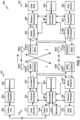
- Fig. 1 is a diagram illustrating a network 100 in which aspects of the present disclosure may be practiced.
- the network 100 may be an LTE network or some other wireless network, such as a 5G or NR network.
- Wireless network 100 may include a number of BSs 110 (shown as BS 110a, BS 110b, BS 110c, and BS 110d) and other network entities.
- a BS is an entity that communicates with user equipment (UEs) and may also be referred to as a base station, a NR BS, a Node B, a gNB, a 5G node B (NB), an access point, a transmit receive point (TRP), and/or the like.
- Each BS may provide communication coverage for a particular geographic area.
- the term "cell" can refer to a coverage area of a BS and/or a BS subsystem serving this coverage area, depending on the context in which the term is used.
- a BS may provide communication coverage for a macro cell, a pico cell, a femto cell, and/or another type of cell.
- a macro cell may cover a relatively large geographic area (e.g., several kilometers in radius) and may allow unrestricted access by UEs with service subscription.
- a pico cell may cover a relatively small geographic area and may allow unrestricted access by UEs with service subscription.
- a femto cell may cover a relatively small geographic area (e.g., a home) and may allow restricted access by UEs having association with the femto cell (e.g., UEs in a closed subscriber group (CSG)).
- a BS for a macro cell may be referred to as a macro BS.
- a BS for a pico cell may be referred to as a pico BS.
- a BS for a femto cell may be referred to as a femto BS or a home BS.
- a BS 110a may be a macro BS for a macro cell 102a
- a BS 110b may be a pico BS for a pico cell 102b
- a BS 110c may be a femto BS for a femto cell 102c.
- a BS may support one or multiple (e.g., three) cells.
- the terms "eNB”, “base station”, “NR BS”, “gNB”, “TRP”, “AP”, “node B", “5G NB”, and “cell” may be used interchangeably herein.
- a cell may not necessarily be stationary, and the geographic area of the cell may move according to the location of a mobile BS.
- the BSs may be interconnected to one another and/or to one or more other BSs or network nodes (not shown) in the access network 100 through various types of backhaul interfaces such as a direct physical connection, a virtual network, and/or the like using any suitable transport network.
- a network controller 130 may couple to a set of BSs and may provide coordination and control for these BSs.
- Network controller 130 may communicate with the BSs via a backhaul.
- the BSs may also communicate with one another, e.g., directly or indirectly via a wireless or wireline backhaul.
- UEs 120 may be dispersed throughout wireless network 100, and each UE may be stationary or mobile.
- a UE may also be referred to as an access terminal, a terminal, a mobile station, a subscriber unit, a station, and/or the like.
- Some UEs may be considered Internet-of-Things (IoT) devices, and/or may be implemented as may be implemented as NB-IoT (narrowband internet of things) devices. Some UEs may be considered a Customer Premises Equipment (CPE).
- UE 120 may be included inside a housing that houses components of UE 120, such as processor components, memory components, and/or the like.
- any number of wireless networks may be deployed in a given geographic area.
- Each wireless network may support a particular RAT and may operate on one or more frequencies.
- a RAT may also be referred to as a radio technology, an air interface, and/or the like.
- a frequency may also be referred to as a carrier, a frequency channel, and/or the like.
- Each frequency may support a single RAT in a given geographic area in order to avoid interference between wireless networks of different RATs.
- NR or 5G RAT networks may be deployed.
- two or more UEs 120 may communicate directly using one or more sidelink channels (e.g., without using a BS 110 as an intermediary to communicate with one another).
- the UEs 120 may communicate using peer-to-peer (P2P) communications, device-to-device (D2D) communications, a vehicle-to-everything (V2X) protocol (e.g., which may include a vehicle-to-vehicle (V2V) protocol, a vehicle-to-infrastructure (V2I) protocol, and/or the like), a mesh network, and/or the like).
- V2X vehicle-to-everything
- the UE 120 may perform scheduling operations, resource selection operations, and/or other operations described elsewhere herein as being performed by the BS 110.
- Fig. 1 is provided merely as an example. Other examples are possible and may differ from what was described with regard to Fig. 1 .
- a transmit processor 220 may receive data from a data source 212 for one or more UEs, select one or more modulation and coding schemes (MCS) for each UE based at least in part on channel quality indicators (CQIs) received from the UE, process (e.g., encode and modulate) the data for each UE based at least in part on the MCS(s) selected for the UE, and provide data symbols for all UEs. Transmit processor 220 may also process system information (e.g., for semi-static resource partitioning information (SRPI) and/or the like) and control information (e.g., CQI requests, grants, upper layer signaling, and/or the like) and provide overhead symbols and control symbols.
- MCS modulation and coding schemes
- CQIs channel quality indicators
- Transmit processor 220 may also process system information (e.g., for semi-static resource partitioning information (SRPI) and/or the like) and control information (e.g., CQI requests, grants, upper layer signal
- Transmit processor 220 may also generate reference symbols for reference signals (e.g., the cell-specific reference signal (CRS)) and synchronization signals (e.g., the primary synchronization signal (PSS) and secondary synchronization signal (SSS)).
- a transmit (TX) multiple-input multiple-output (MIMO) processor 230 may perform spatial processing (e.g., precoding) on the data symbols, the control symbols, the overhead symbols, and/or the reference symbols, if applicable, and may provide T output symbol streams to T modulators (MODs) 232a through 232t. Each modulator 232 may process a respective output symbol stream (e.g., for OFDM and/or the like) to obtain an output sample stream.
- Each modulator 232 may further process (e.g., convert to analog, amplify, filter, and upconvert) the output sample stream to obtain a downlink signal.
- T downlink signals from modulators 232a through 232t may be transmitted via T antennas 234a through 234t, respectively.
- the synchronization signals can be generated with location encoding to convey additional information.
- antennas 252a through 252r may receive the downlink signals from BS 110 and/or other base stations and may provide received signals to demodulators (DEMODs) 254a through 254r, respectively.
- Each demodulator 254 may condition (e.g., filter, amplify, downconvert, and digitize) a received signal to obtain input samples.
- Each demodulator 254 may further process the input samples (e.g., for OFDM and/or the like) to obtain received symbols.
- a MIMO detector 256 may obtain received symbols from all R demodulators 254a through 254r, perform MIMO detection on the received symbols if applicable, and provide detected symbols.
- a receive processor 258 may process (e.g., demodulate and decode) the detected symbols, provide decoded data for UE 120 to a data sink 260, and provide decoded control information and system information to a controller/processor 280.
- a channel processor may determine reference signal received power (RSRP), received signal strength indicator (RSSI), reference signal received quality (RSRQ), channel quality indicator (CQI), and/or the like.
- a transmit processor 264 may receive and process data from a data source 262 and control information (e.g., for reports comprising RSRP, RSSI, RSRQ, CQI, and/or the like) from controller/processor 280. Transmit processor 264 may also generate reference symbols for one or more reference signals. The symbols from transmit processor 264 may be precoded by a TX MIMO processor 266 if applicable, further processed by modulators 254a through 254r (e.g., for DFT-s-OFDM, CP-OFDM, and/or the like), and transmitted to BS 110.
- control information e.g., for reports comprising RSRP, RSSI, RSRQ, CQI, and/or the like
- Transmit processor 264 may also generate reference symbols for one or more reference signals.
- the symbols from transmit processor 264 may be precoded by a TX MIMO processor 266 if applicable, further processed by modulators 254a through 254r (e.g., for DFT-
- the uplink signals from UE 120 and other UEs may be received by antennas 234, processed by demodulators 232, detected by a MIMO detector 236 if applicable, and further processed by a receive processor 238 to obtain decoded data and control information sent by UE 120.
- Receive processor 238 may provide the decoded data to a data sink 239 and the decoded control information to controller/processor 240.
- BS 110 may include communication unit 244 and communicate to network controller 130 via communication unit 244.
- Network controller 130 may include communication unit 294, controller/processor 290, and memory 292.
- Fig. 2 is provided merely as an example. Other examples are possible and may differ from what was described with regard to Fig. 2 .
- Fig. 3A shows an example frame structure 300 for frequency division duplexing (FDD) in a telecommunications system (e.g., NR).
- the transmission timeline for each of the downlink and uplink may be partitioned into units of radio frames.
- Each radio frame may have a predetermined duration and may be partitions into a set of Z (Z ⁇ 1) subframes (e.g., with indices of 0 through Z-1).
- Each subframe may include a set of slots (e.g., two slots per subframe are shown in Fig. 3A ).
- Each slot may include a set of L symbol periods.
- each slot may include seven symbol periods (e.g., as shown in Fig. 3A ), fifteen symbol periods, and/or the like.
- the subframe may include 2L symbol periods, where the 2L symbol periods in each subframe may be assigned indices of 0 through 2L-1.
- a scheduling unit for the FDD may frame-based, subframe-based, slot-based, symbol-based, and/or the like.
- a wireless communication structure may refer to a periodic time-bounded communication unit defined by a wireless communication standard and/or protocol. Additionally, or alternatively, different configurations of wireless communication structures than those shown in Fig. 3A may be used.
- a base station may transmit synchronization signals.
- a base station may transmit a primary synchronization signal (PSS), a secondary synchronization signal (SSS), and/or the like, on the downlink for each cell supported by the base station.
- PSS and SSS may be used by UEs for cell search and acquisition.
- the PSS may be used by UEs to determine symbol timing
- the SSS may be used by UEs to determine a physical cell identifier, associated with the base station, and frame timing.
- the base station may also transmit a physical broadcast channel (PBCH).
- the PBCH may carry some system information, such as system information that supports initial access by UEs.
- the base station may transmit the PSS, the SSS, and/or the PBCH in accordance with a synchronization communication hierarchy (e.g., a synchronization signal (SS) hierarchy) including multiple synchronization communications (e.g., SS blocks), as described below in connection with Fig. 3B .
- a synchronization communication hierarchy e.g., a synchronization signal (SS) hierarchy
- multiple synchronization communications e.g., SS blocks
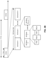
- Fig. 3B is a block diagram conceptually illustrating an example SS hierarchy, which is an example of a synchronization communication hierarchy.
- the SS hierarchy may include an SS burst set, which may include a plurality of SS bursts (identified as SS burst 0 through SS burst B-1, where B is a maximum number of repetitions of the SS burst that may be transmitted by the base station).
- each SS burst may include one or more SS blocks (identified as SS block 0 through SS block (b max_SS-1 ), where b max_SS-1 is a maximum number of SS blocks that can be carried by an SS burst).
- An SS burst set may be periodically transmitted by a wireless node, such as every X milliseconds, as shown in Fig. 3B .
- an SS burst set may have a fixed or dynamic length, shown as Y milliseconds in Fig. 3B .
- the SS block may be at least four symbol periods in length, where each symbol carries one or more of the PSS (e.g., occupying one symbol), the SSS (e.g., occupying one symbol), and/or the PBCH (e.g., occupying two symbols).
- the symbols of an SS block are consecutive, as shown in Fig. 3B .
- the symbols of an SS block are non-consecutive.
- one or more SS blocks of the SS burst may be transmitted in consecutive radio resources (e.g., consecutive symbol periods) during one or more subframes. Additionally, or alternatively, one or more SS blocks of the SS burst may be transmitted in non-consecutive radio resources.
- the SS bursts may have a burst period, whereby the SS blocks of the SS burst are transmitted by the base station according to the burst period. In other words, the SS blocks may be repeated during each SS burst.
- the SS burst set may have a burst set periodicity, whereby the SS bursts of the SS burst set are transmitted by the base station according to the fixed burst set periodicity. In other words, the SS bursts may be repeated during each SS burst set.
- the base station may transmit system information, such as system information blocks (SIBs) on a physical downlink shared channel (PDSCH) in certain subframes.
- SIBs system information blocks
- the base station may transmit control information/data on a physical downlink control channel (PDCCH) in C symbol periods of a subframe, where B may be configurable for each subframe.
- the base station may transmit traffic data and/or other data on the PDSCH in the remaining symbol periods of each subframe.
- Fig. 4 shows an example subframe format 410 with a normal cyclic prefix.
- the available time frequency resources may be partitioned into resource blocks.
- Each resource block may cover a set to of subcarriers (e.g., 12 subcarriers) in one slot and may include a number of resource elements.
- Each resource element may cover one subcarrier in one symbol period (e.g., in time) and may be used to send one modulation symbol, which may be a real or complex value.
- subframe format 410 may be used for transmission of SS blocks that carry the PSS, the SSS, the PBCH, and/or the like, as described herein.
- An interlace structure may be used for each of the downlink and uplink for FDD in certain telecommunications systems (e.g., NR).
- Q interlaces with indices of 0 through Q - 1 may be defined, where Q may be equal to 4, 6, 8, 10, or some other value.
- Each interlace may include subframes that are spaced apart by Q frames.
- interlace q may include subframes q, q + Q, q + 2Q, etc., where q ⁇ ⁇ 0,...,Q-1 ⁇ .
- a UE may be located within the coverage of multiple BSs. One of these BSs may be selected to serve the UE. The serving BS may be selected based at least in part on various criteria such as received signal strength, received signal quality, path loss, and/or the like. Received signal quality may be quantified by a signal-to-noise-and-interference ratio (SINR), or a reference signal received quality (RSRQ), or some other metric. The UE may operate in a dominant interference scenario in which the UE may observe high interference from one or more interfering BSs.
- SINR signal-to-noise-and-interference ratio
- RSRQ reference signal received quality
- New radio may refer to radios configured to operate according to a new air interface (e.g., other than Orthogonal Frequency Divisional Multiple Access (OFDMA)-based air interfaces) or fixed transport layer (e.g., other than Internet Protocol (IP)).
- OFDM Orthogonal Frequency Divisional Multiple Access
- IP Internet Protocol
- NR may utilize OFDM with a CP (herein referred to as cyclic prefix OFDM or CP-OFDM) and/or SC-FDM on the uplink, may utilize CP-OFDM on the downlink and include support for half-duplex operation using time division duplexing (TDD).
- OFDM Orthogonal Frequency Divisional Multiple Access
- IP Internet Protocol
- NR may include Enhanced Mobile Broadband (eMBB) service targeting wide bandwidth (e.g., 80 megahertz (MHz) and beyond), millimeter wave (mmW) or above sub-6GHz targeting high carrier frequency (e.g., 27 gigahertz (GHz)), massive MTC (mMTC) targeting non-backward compatible MTC techniques, and/or mission critical targeting ultra reliable low latency communications (URLLC) service.
- eMBB Enhanced Mobile Broadband
- mmW millimeter wave
- mMTC massive MTC
- URLLC ultra reliable low latency communications
- NR resource blocks may span 12 sub-carriers with a sub-carrier bandwidth of 60 or 120 kilohertz (kHz) over a 0.1 millisecond (ms) duration.
- Each radio frame may include 40 subframes with a length of 10 ms. Consequently, each subframe may have a length of 0.25 ms.
- Each subframe may indicate a link direction (e.g., DL or UL) for data transmission and the link direction for each subframe may be dynamically switched.
- Each subframe may include DL/UL data as well as DL/UL control data.
- NR may support a different air interface, other than an OFDM-based interface.
- NR networks may include entities such central units or distributed units.
- Fig. 4 is provided as an example. Other examples are possible and may differ from what was described with regard to Fig. 4 .
- Fig. 5 is a diagram 500 showing an example of a DL-centric subframe or wireless communication structure.
- the DL-centric subframe may include a control portion 502.
- the control portion 502 may exist in the initial or beginning portion of the DL-centric subframe.
- the control portion 502 may include various scheduling information and/or control information corresponding to various portions of the DL-centric subframe.
- the control portion 502 may be a physical DL control channel (PDCCH), as indicated in Fig. 5 .
- PDCH physical DL control channel
- the DL-centric subframe may also include a DL data portion 504.
- the DL data portion 504 may sometimes be referred to as the payload of the DL-centric subframe.
- the DL data portion 504 may include the communication resources utilized to communicate DL data from the scheduling entity (e.g., UE or BS) to the subordinate entity (e.g., UE).
- the DL data portion 504 may be a physical DL shared channel (PDSCH).
- PDSCH physical DL shared channel
- the DL-centric subframe may also include an UL short burst portion 506.
- the UL short burst portion 506 may sometimes be referred to as an UL burst, an UL burst portion, a common UL burst, a short burst, an UL short burst, a common UL short burst, a common UL short burst portion, and/or various other suitable terms.
- the UL short burst portion 506 may include one or more reference signals. Additionally, or alternatively, the UL short burst portion 506 may include feedback information corresponding to various other portions of the DL-centric subframe.
- the UL short burst portion 506 may include feedback information corresponding to the control portion 502 and/or the data portion 504.
- information that may be included in the UL short burst portion 506 include an acknowledgment (ACK) signal (e.g., a physical uplink control channel (PUCCH) ACK, a physical uplink shared channel (PUSCH) ACK, an immediate ACK), a negative ACK (NACK) signal (e.g., a PUCCH NACK, a PUSCH NACK, an immediate NACK), a scheduling request (SR), a buffer status report (BSR), a HARQ indicator, a channel state indication (CSI), a channel quality indicator (CQI), a sounding reference signal (SRS), a demodulation reference signal (DMRS), PUSCH data, and/or various other suitable types of information.
- the UL short burst portion 506 may include additional or alternative information, such as information pertaining to random access channel (RACH) procedures, scheduling requests, and various other suitable
- the end of the DL data portion 504 may be separated in time from the beginning of the UL short burst portion 506.
- This time separation may sometimes be referred to as a gap, a guard period, a guard interval, and/or various other suitable terms.
- This separation provides time for the switch-over from DL communication (e.g., reception operation by the subordinate entity (e.g., UE)) to UL communication (e.g., transmission by the subordinate entity (e.g., UE)).
- DL communication e.g., reception operation by the subordinate entity (e.g., UE)
- UL communication e.g., transmission by the subordinate entity (e.g., UE)
- Fig. 5 is provided merely as an example. Other examples are possible and may differ from what was described with regard to Fig. 5 .
- Fig. 6 is a diagram 600 showing an example of an UL-centric subframe or wireless communication structure.
- the UL-centric subframe may include a control portion 602.
- the control portion 602 may exist in the initial or beginning portion of the UL-centric subframe.
- the control portion 602 in Fig. 6 may be similar to the control portion 502 described above with reference to Fig. 5 .
- the UL-centric subframe may also include an UL long burst portion 604.
- the UL long burst portion 604 may sometimes be referred to as the payload of the UL-centric subframe.
- the UL portion may refer to the communication resources utilized to communicate UL data from the subordinate entity (e.g., UE) to the scheduling entity (e.g., UE or BS).
- the control portion 602 may be a physical DL control channel (PDCCH).
- PDCH physical DL control channel
- two or more subordinate entities may communicate with each other using sidelink signals.
- Real-world applications of such sidelink communications may include public safety, proximity services, UE-to-network relaying, vehicle-to-vehicle (V2V) communications, Internet of Everything (IoE) communications, IoT communications, mission-critical mesh, and/or various other suitable applications.
- a sidelink signal may refer to a signal communicated from one subordinate entity (e.g., UE1) to another subordinate entity (e.g., UE2) without relaying that communication through the scheduling entity (e.g., UE or BS), even though the scheduling entity may be utilized for scheduling and/or control purposes.
- the sidelink signals may be communicated using a licensed spectrum (unlike wireless local area networks, which typically use an unlicensed spectrum).
- a UE may transmit uplink control information (UCI), such as CSI and/or HARQ feedback, and uplink data, such as an uplink shared channel (e.g., the physical uplink shared channel, or PUSCH).
- UCI uplink control information
- uplink data such as an uplink shared channel (e.g., the physical uplink shared channel, or PUSCH).
- UCI uplink control information
- the UE may perform rate matching of the uplink shared channel to transmit the UCI on the uplink shared channel (e.g., when the UCI is HARQ feedback with more than 2 bits).
- the UE may puncture the uplink shared channel to transmit the UCI on the uplink shared channel (e.g., when the UCI is HARQ feedback with 1 or 2 bits).
- Certain challenges may arise when piggybacking the UCI on the uplink shared channel. For example, if too many uplink shared channel resources are punctured in close proximity, a single code block (CB) may be heavily punctured, thereby decreasing throughput of the uplink shared channel. Furthermore, if UCI resources are in close proximity in the uplink shared channel, time diversity may be weak, which may lead to problems in certain scenarios, such as high-Doppler-effect scenarios. Still further, if the HARQ feedback punctures the CSI, uplink shared channel performance may be negatively impacted.
- CB code block
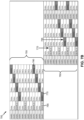
- Figs. 7A and 7B are diagrams illustrating examples 700 of resource allocation for UCI piggybacking on a PUSCH in 5G, in accordance with various aspects of the present disclosure.
- Fig. 7A shows an example wherein frequency hopping is not used
- Fig. 7B shows an example wherein frequency hopping is used.
- Figs. 7A and 7B show resources of an uplink shared channel, which may be situated in an UL region of a slot such as UL long burst portion (e.g., UL long burst portion 604).
- each rectangle of the grid corresponds to a resource element.
- each row of the grid may correspond to a frequency or subcarrier (e.g., a subcarrier for CP-OFDM or a virtual subcarrier for DFT-s-OFDM), and each column of the grid may correspond to a symbol. Therefore, moving rightward in the grid may increase time, and moving upward in the grid may increase frequency with regard to a corresponding resource.
- a frequency or subcarrier e.g., a subcarrier for CP-OFDM or a virtual subcarrier for DFT-s-OFDM
- mapping of the plurality of CSI signals may be based at least in part on the following pseudo-code, wherein:
- the UE 120 skips resource elements that include a phase-tracking reference signal so that phase-tracking reference signals are not punctured by the CSI signal.
- the UE 120 maps the CSI signals to increasing frequency resources. For example, the UE 120 may start at a lowest frequency resource or subcarrier of the physical shared channel, and may map each CSI of the CSI signals to an increasing frequency or subcarrier.
- the above pseudo-code is provided merely as an example, and other aspects are contemplated herein.
- the UE 120 may map CSI to first resource elements that are distributed in frequency, as described above.
- the first resource elements may be distributed in frequency according to the step size d.
- the step size can be greater than 1.
- the step size may be based at least in part on the amount of CSI to be mapped. For example, as indicated above, the step size is determined to be 1 when the number of symbols of the plurality of CSI signals is greater than or equal to the number of subcarriers that do not include a phase-tracking reference signal, and is determined to be the floor of M l / Q CSI when the number of symbols of the CSI signal is less than the number of subcarriers that do not include a phase-tracking reference signal.
- a step size of 1 is shown with regard to the CSI Part 2 in Fig. 7A (e.g., reference number 715).
- the CSI Part 1 has a step size of 1 and the CSI Part 2 has a step size of 3. In some aspects, this may be based at least in part on a number of REs for which CSI Part 1 is to be mapped and a number of REs for which CSI Part 2 is to be mapped.
- the above algorithm provides for frequency-first, time-second mapping.
- the conditional at Step 2.2.8 and 2.2.8.1 causes all resource elements of a first symbol to be mapped before resource elements of a second symbol are mapped, since k is a subcarrier index, M is a total number of subcarriers, and l is an OFDM symbol index.
- the while loop at Step 2.2.4 and 2.2.4.1 cause phase-tracking reference signals to be excluded from the first resource elements.
- a plurality of HARQ feedback signals may be mapped in a diagonal pattern with regard to symbols and subcarriers of the uplink shared channel.
- a HARQ feedback signal may include a HARQ ACK and/or a HARQ NACK.
- the second HARQ feedback signal is mapped to a next symbol in time and a next subcarrier in relation to the first HARQ feedback signal.
- mapping the HARQ feedback signals in the diagonal pattern frequency and time diversity of the HARQ feedback signals is improved. Mapping the HARQ feedback signals in the diagonal pattern is provided as an example. Techniques and apparatuses described herein are not limited to those in which a diagonal pattern is used to map the plurality of HARQ feedback signals.
- the HARQ feedback signals may be mapped to resource elements that are different than (e.g., orthogonal to, non-overlapped with, etc.) resource elements used for the CSI signals.
- the DMRS may be mapped to a first symbol of the uplink shared channel
- the CSI signals may be mapped to second and third symbols of the uplink shared channel
- the HARQ feedback signals may be mapped to a remainder of the symbols of the uplink shared channel.
- the HARQ feedback may be mapped to resource elements that are reserved for the HARQ feedback, and the CSI may not be mapped to the resource elements that are reserved for the HARQ feedback. This may reduce or eliminate puncturing of the CSI signals by the HARQ feedback signals.
- the diagonal pattern may skip a resource associated with a reference signal.
- a second DMRS symbol may be included in the uplink shared channel. In such a case, the diagonal pattern may skip the second DMRS symbol and resume in a next symbol.
- a first CSI when frequency hopping is performed, a first CSI may provided in a first frequency hop.
- the frequency first resource allocation technique may be used to allocate resources for the first CSI, as described in more detail above.
- a second CSI when frequency hopping is performed, a second CSI may be provided in a second frequency hop.
- the frequency first resource allocation technique may be used to allocate resources for the second CSI, as described in more detail above.
- step sizes in the frequency and time directions are determined.
- the techniques and apparatuses described herein are not limited to a step size of 1 (e.g., since d f is based at least in part on the number of subcarriers in the uplink shared channel and the number of symbols of the HARQ feedback), although using a step size of 1 is possible for techniques and apparatuses described herein.
- the UE 120 determines to skip resource elements that are already used for a reference signal (e.g., DMRS or PTRS), CSI, or another HARQ feedback signal.
- HARQ feedback signals are mapped to resource elements in a diagonal pattern.
- other frequency and time resource mapping approaches may be used, and the techniques and apparatuses described herein are not limited to those involving a diagonal resource pattern.
- the step size, in the frequency direction, of the HARQ feedback may be based at least in part on an amount of the HARQ feedback.
- the step size is based at least in part on the number of subcarriers in the uplink shared channel and the number of symbols of the HARQ feedback.
- Figs. 7A and 7B are provided as an example. Other examples are possible and may differ from what was described with respect to Figs. 7A and 7B .
- Fig. 8 is a diagram illustrating an example of a system 800 for transmitting a PUSCH with UCI piggybacking in 5G, in accordance with various aspects of the present disclosure.
- System 800 may include one or more of the components of UE 120 described in connection with Fig. 2 , above.
- a UCI mapper component 830 may map the UCI (e.g., the CSI signals and/or the HARQ feedback signals) to resource elements of the uplink shared channel, as described in more detail in connection with Fig. 8 .
- the UCI may be mapped to subcarriers such as physical subcarriers.
- the UCI may be allocated to virtual subcarriers before DFT spreading is applied and the output signal is generated.
- Virtual subcarriers are known and described, for example, in 3GPP Technical Specification 36.211 (e.g., Section 5.3.3).
- a virtual subcarrier may be associated with an index value i, which may be the modulated symbol index for a length of M complex-valued symbols d (0),..., d ( M symb -1). These may be divided into M symb / M sc PUSCH sets, each corresponding to one SC-FDMA symbol.
- a DFT component 835 may perform discrete Fourier transform (DFT) spreading of the uplink shared channel.
- a sub-band mapping component 840 may map the output of the DFT spreading to sub-bands (e.g., physical subcarriers) of an output signal.
- An IFFT component 845 may perform an inverse fast Fourier transform (IFFT) to prepare the uplink shared channel or output signal for transmission.
- a transmitter component 850 may transmit the uplink shared channel or output signal.
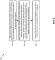
- Fig. 9 is a diagram illustrating an example process 900 performed, by a UE, in accordance with various aspects of the present disclosure.
- Example process 900 is an example where a UE (e.g., UE 120) performs resource allocation for UCI piggybacking on a PUSCH in 5G.
- a UE e.g., UE 120
- process 900 includes mapping channel state information (CSI) to first resource elements that are distributed in frequency, wherein the first resource elements are in a set of resources allocated on an uplink shared channel (block 910).
- the UE e.g., using controller/processor 280, transmit processor 264, TX MIMO processor 266, MOD 254, antenna 252, and/or the like
- the first resource elements may be in a set of resources of an uplink shared channel (e.g., in a slot).
- the first resource elements may be located after a reference signal (e.g., DMRS) of the uplink shared channel.
- the first resource elements may be located immediately after the reference signal.
- the first resource elements may be located elsewhere in a slot.
- process 900 includes mapping hybrid automatic repeat request (HARQ) feedback to second resource elements that are distributed in frequency, wherein the second resource elements are in the set of resources, wherein the second resource elements are reserved for the HARQ feedback and are different from the first resource elements (block 920).
- the UE e.g., using controller/processor 280, transmit processor 264, TX MIMO processor 266, MOD 254, antenna 252, and/or the like
- the second resource elements are different than the first resource elements.
- the second resource elements may be orthogonal to the first resource elements.
- the second resource elements are reserved for the HARQ feedback.
- Process 900 may include additional aspects, such as any single aspect and/or any combination of aspects described below and/or in connection with one or more other processes described elsewhere herein.
- a first slot boundary of the uplink shared channel is reached, the diagonal pattern wraps around to a second slot boundary of the uplink shared channel that is opposite from the first slot boundary.
- the first resource elements are located after a reference signal of the uplink shared channel. In some aspects, the first resource elements are distributed in frequency.
- the plurality of CSI signals when the uplink shared channel is not configured for frequency hopping, include first CSI and second CSI, and wherein the first CSI is mapped to resource elements that are adjacent to resource elements to which the second CSI is mapped.
- the plurality of CSI signals include first CSI and second CSI, and when the uplink shared channel is configured for frequency hopping, the first CSI is mapped to a first frequency hop and the second CSI is mapped to a second frequency hop.
- the plurality of CSI signals and the plurality of HARQ feedback signals puncture data symbols of the uplink shared channel.
- rate matching is used for the plurality of CSI signals and the plurality of HARQ feedback signals.
- the diagonal pattern skips a resource element associated with a reference signal.
- the second resource elements are mapped after a reference signal of the uplink shared channel.
- the first resource elements are distributed in frequency.
- the plurality of HARQ feedback signals puncture data symbols of the uplink shared channel.
- rate matching is used for the plurality of CSI signals and the plurality of HARQ feedback signals.
- one or more resource elements comprising a phase-tracking reference signal are excluded from the first resource elements.
- the first resource elements and the second resource elements are distributed in frequency based at least in part on respective step sizes, wherein the respective step sizes are based at least in part on respective amounts of the CSI and the HARQ feedback.
- mapping the CSI and mapping the HARQ feedback are performed in a frequency-first, time-second manner.
- the first resource elements and the second resource elements are orthogonal such that the HARQ feedback does not puncture the CSI.
- process 900 may include additional blocks, fewer blocks, different blocks, or differently arranged blocks than those depicted in Fig. 9 . Additionally, or alternatively, two or more of the blocks of process 900 may be performed in parallel.
- the term component is intended to be broadly construed as hardware, firmware, or a combination of hardware and software.
- a processor is implemented in hardware, firmware, or a combination of hardware and software.
- satisfying a threshold may refer to a value being greater than the threshold, greater than or equal to the threshold, less than the threshold, less than or equal to the threshold, equal to the threshold, not equal to the threshold, and/or the like.
- a phrase referring to "at least one of" a list of items refers to any combination of those items, including single members.
- "at least one of: a, b, or c" is intended to cover a, b, c, a-b, a-c, b-c, and a-b-c, as well as any combination with multiples of the same element (e.g., a-a, a-a-a, a-a-b, a-a-c, a-b-b, a-c-c, b-b, b-b-b, b-b-c, c-c, and c-c-c or any other ordering of a, b, and c).
Landscapes
- Engineering & Computer Science (AREA)
- Signal Processing (AREA)
- Computer Networks & Wireless Communication (AREA)
- Mobile Radio Communication Systems (AREA)
- Detection And Prevention Of Errors In Transmission (AREA)
- Radio Relay Systems (AREA)
Applications Claiming Priority (3)
| Application Number | Priority Date | Filing Date | Title |
|---|---|---|---|
| US201762588301P | 2017-11-17 | 2017-11-17 | |
| US16/192,482 US11122549B2 (en) | 2017-11-17 | 2018-11-15 | Channel state information and hybrid automatic repeat request feedback resource allocation in 5G |
| PCT/US2018/061471 WO2019099794A1 (en) | 2017-11-17 | 2018-11-16 | Channel state information and hybrid automatic repeat request feedback resource allocation in 5g |
Publications (2)
| Publication Number | Publication Date |
|---|---|
| EP3711226A1 EP3711226A1 (en) | 2020-09-23 |
| EP3711226B1 true EP3711226B1 (en) | 2025-04-09 |
Family
ID=66534698
Family Applications (1)
| Application Number | Title | Priority Date | Filing Date |
|---|---|---|---|
| EP18836699.1A Active EP3711226B1 (en) | 2017-11-17 | 2018-11-16 | Channel state information and hybrid automatic repeat request feedback resource allocation in 5g |
Country Status (9)
| Country | Link |
|---|---|
| US (2) | US11122549B2 (enExample) |
| EP (1) | EP3711226B1 (enExample) |
| JP (1) | JP7383610B2 (enExample) |
| KR (1) | KR102721661B1 (enExample) |
| CN (1) | CN111357225B (enExample) |
| BR (1) | BR112020009730A2 (enExample) |
| SG (1) | SG11202003419VA (enExample) |
| TW (1) | TWI771526B (enExample) |
| WO (1) | WO2019099794A1 (enExample) |
Families Citing this family (14)
| Publication number | Priority date | Publication date | Assignee | Title |
|---|---|---|---|---|
| CN109802782B (zh) * | 2017-11-17 | 2021-05-14 | 中国信息通信研究院 | 一种上行控制信息的传输方法、装置和系统 |
| US11122549B2 (en) | 2017-11-17 | 2021-09-14 | Qualcomm Incorporated | Channel state information and hybrid automatic repeat request feedback resource allocation in 5G |
| JP7313342B2 (ja) * | 2018-05-08 | 2023-07-24 | パナソニック インテレクチュアル プロパティ コーポレーション オブ アメリカ | 端末、通信方法及び集積回路 |
| US11233620B2 (en) | 2018-11-30 | 2022-01-25 | T-Mobile Usa, Inc. | Scheduling HARQ transmissions in mini-slots |
| US11133909B2 (en) * | 2018-11-30 | 2021-09-28 | T-Mobile Usa, Inc. | Scheduling HARQ transmissions in mini-slots based on fading conditions |
| US11589348B2 (en) * | 2019-08-27 | 2023-02-21 | Qualcomm Incorporated | Reception of overlapping physical downlink shared channel communications |
| US12003458B2 (en) * | 2019-10-01 | 2024-06-04 | Qualcomm Incorporated | Sidelink feedback transmission and feedback resource determination |
| WO2021066571A1 (ko) * | 2019-10-04 | 2021-04-08 | 엘지전자 주식회사 | Nr v2x에서 사이드링크 harq 피드백과 관련된 정보를 전송하는 방법 및 장치 |
| BR112022007881A2 (pt) | 2019-11-04 | 2022-07-05 | Guangdong Oppo Mobile Telecommunications Corp Ltd | Método de operação de um equipamento de usuário, e equipamento de usuário |
| US12088417B2 (en) * | 2020-05-18 | 2024-09-10 | Qualcomm Incorporated | Quantized CQI feedback for HARQ based retransmissions |
| EP4173196A1 (en) * | 2020-06-24 | 2023-05-03 | Qualcomm Incorporated | Self-contained feedback transmission for sidelink communication in unlicensed spectrum |
| CN116636154A (zh) * | 2020-12-28 | 2023-08-22 | 高通股份有限公司 | 信道状态信息的非周期性报告 |
| CN115174001B (zh) * | 2022-07-19 | 2023-05-02 | 四川创智联恒科技有限公司 | 一种nr5g中dmrs符号空闲re的使用方法、存储介质及电子设备 |
| US20250048401A1 (en) * | 2023-08-04 | 2025-02-06 | Qualcomm Incorporated | Managing interlaced sidelink feedback |
Family Cites Families (13)
| Publication number | Priority date | Publication date | Assignee | Title |
|---|---|---|---|---|
| EP2648470B1 (en) * | 2010-03-22 | 2018-05-02 | Samsung Electronics Co., Ltd | Multiplexing control and data information from a user equipment in a physical data channel |
| CN103095398B (zh) * | 2011-11-04 | 2017-04-12 | 华为技术有限公司 | 传输控制信息的方法、用户设备和基站 |
| US9107191B2 (en) * | 2011-11-11 | 2015-08-11 | Qualcomm Incorporated | System and method for managing simultaneous uplink signal transmissions in carrier aggregation systems |
| KR101972945B1 (ko) * | 2012-09-18 | 2019-04-29 | 삼성전자 주식회사 | 무선 통신 시스템에서 채널 상태 정보 송수신 방법 및 장치 |
| CN103795509A (zh) * | 2012-11-02 | 2014-05-14 | 北京三星通信技术研究有限公司 | 一种传输harq指示信息的方法和设备 |
| KR20150105353A (ko) | 2013-01-03 | 2015-09-16 | 엘지전자 주식회사 | 무선 통신 시스템에서 상향링크 신호를 전송하는 방법 및 장치 |
| CN106257856B (zh) * | 2015-06-19 | 2021-02-02 | 北京三星通信技术研究有限公司 | 一种传输上行控制信息的方法 |
| EP4236545A3 (en) * | 2015-07-30 | 2023-09-13 | Apple Inc. | Ofdma-based multiplexing of uplink control information |
| WO2017029213A1 (en) * | 2015-08-14 | 2017-02-23 | Telefonaktiebolaget Lm Ericsson (Publ) | Facilitated positioning of wireless communication devices |
| US10492184B2 (en) * | 2016-12-09 | 2019-11-26 | Samsung Electronics Co., Ltd. | Multiplexing control information in a physical uplink data channel |
| US10440698B2 (en) * | 2017-02-06 | 2019-10-08 | Qualcomm Incorporated | Transmitting uplink control information |
| US11122549B2 (en) | 2017-11-17 | 2021-09-14 | Qualcomm Incorporated | Channel state information and hybrid automatic repeat request feedback resource allocation in 5G |
| US11121825B2 (en) * | 2017-11-26 | 2021-09-14 | Qualcomm Incorporated | Mapping uplink control information to uplink data channel in wireless communication |
-
2018
- 2018-11-15 US US16/192,482 patent/US11122549B2/en active Active
- 2018-11-16 SG SG11202003419VA patent/SG11202003419VA/en unknown
- 2018-11-16 BR BR112020009730-6A patent/BR112020009730A2/pt unknown
- 2018-11-16 TW TW107140795A patent/TWI771526B/zh active
- 2018-11-16 CN CN201880073942.9A patent/CN111357225B/zh active Active
- 2018-11-16 KR KR1020207013872A patent/KR102721661B1/ko active Active
- 2018-11-16 WO PCT/US2018/061471 patent/WO2019099794A1/en not_active Ceased
- 2018-11-16 JP JP2020527094A patent/JP7383610B2/ja active Active
- 2018-11-16 EP EP18836699.1A patent/EP3711226B1/en active Active
-
2021
- 2021-09-14 US US17/447,621 patent/US12052719B2/en active Active
Also Published As
| Publication number | Publication date |
|---|---|
| EP3711226A1 (en) | 2020-09-23 |
| JP7383610B2 (ja) | 2023-11-20 |
| US12052719B2 (en) | 2024-07-30 |
| CN111357225A (zh) | 2020-06-30 |
| US20190159194A1 (en) | 2019-05-23 |
| KR20200080261A (ko) | 2020-07-06 |
| CN111357225B (zh) | 2022-10-21 |
| KR102721661B1 (ko) | 2024-10-23 |
| TWI771526B (zh) | 2022-07-21 |
| WO2019099794A1 (en) | 2019-05-23 |
| TW201924257A (zh) | 2019-06-16 |
| US11122549B2 (en) | 2021-09-14 |
| JP2021503835A (ja) | 2021-02-12 |
| US20220095298A1 (en) | 2022-03-24 |
| SG11202003419VA (en) | 2020-05-28 |
| BR112020009730A2 (pt) | 2020-11-03 |
Similar Documents
| Publication | Publication Date | Title |
|---|---|---|
| US11337195B2 (en) | Selectively multiplexing physical uplink shared channel (PUSCH) and physical uplink control channel (PUCCH) communications | |
| US12052719B2 (en) | Channel state information and hybrid automatic repeat request feedback resource allocation in 5G | |
| AU2019266295B2 (en) | Allocating physical uplink control channel (PUCCH) resources for ultra-reliable low latency communication (URLLC) | |
| US11395270B2 (en) | Uplink control information payload size | |
| US11540258B2 (en) | Construction and mapping of compact uplink control information (UCI) over physical uplink shared channel (PUSCH) | |
| US11616595B2 (en) | Multi-channel listen before talk with wideband transmission in new radio in unlicensed spectrum | |
| US20190223085A1 (en) | Uplink control channel resource allocation | |
| US11463205B2 (en) | Techniques for transmitting sidelink HARQ feedback | |
| US10856284B2 (en) | Resource allocation for a short transmission time interval (STTI) system |
Legal Events
| Date | Code | Title | Description |
|---|---|---|---|
| STAA | Information on the status of an ep patent application or granted ep patent |
Free format text: STATUS: UNKNOWN |
|
| STAA | Information on the status of an ep patent application or granted ep patent |
Free format text: STATUS: THE INTERNATIONAL PUBLICATION HAS BEEN MADE |
|
| PUAI | Public reference made under article 153(3) epc to a published international application that has entered the european phase |
Free format text: ORIGINAL CODE: 0009012 |
|
| STAA | Information on the status of an ep patent application or granted ep patent |
Free format text: STATUS: REQUEST FOR EXAMINATION WAS MADE |
|
| 17P | Request for examination filed |
Effective date: 20200427 |
|
| AK | Designated contracting states |
Kind code of ref document: A1 Designated state(s): AL AT BE BG CH CY CZ DE DK EE ES FI FR GB GR HR HU IE IS IT LI LT LU LV MC MK MT NL NO PL PT RO RS SE SI SK SM TR |
|
| AX | Request for extension of the european patent |
Extension state: BA ME |
|
| DAV | Request for validation of the european patent (deleted) | ||
| DAX | Request for extension of the european patent (deleted) | ||
| STAA | Information on the status of an ep patent application or granted ep patent |
Free format text: STATUS: EXAMINATION IS IN PROGRESS |
|
| 17Q | First examination report despatched |
Effective date: 20211206 |
|
| REG | Reference to a national code |
Ref legal event code: R079 Free format text: PREVIOUS MAIN CLASS: H04L0001180000 Ref country code: DE Ref legal event code: R079 Ref document number: 602018081015 Country of ref document: DE Free format text: PREVIOUS MAIN CLASS: H04L0001180000 Ipc: H04L0001182900 |
|
| GRAP | Despatch of communication of intention to grant a patent |
Free format text: ORIGINAL CODE: EPIDOSNIGR1 |
|
| STAA | Information on the status of an ep patent application or granted ep patent |
Free format text: STATUS: GRANT OF PATENT IS INTENDED |
|
| RIC1 | Information provided on ipc code assigned before grant |
Ipc: H04W 72/21 20230101ALN20241030BHEP Ipc: H04L 5/00 20060101ALI20241030BHEP Ipc: H04L 1/1607 20230101ALI20241030BHEP Ipc: H04L 1/1829 20230101AFI20241030BHEP |
|
| INTG | Intention to grant announced |
Effective date: 20241112 |
|
| GRAS | Grant fee paid |
Free format text: ORIGINAL CODE: EPIDOSNIGR3 |
|
| GRAA | (expected) grant |
Free format text: ORIGINAL CODE: 0009210 |
|
| STAA | Information on the status of an ep patent application or granted ep patent |
Free format text: STATUS: THE PATENT HAS BEEN GRANTED |
|
| AK | Designated contracting states |
Kind code of ref document: B1 Designated state(s): AL AT BE BG CH CY CZ DE DK EE ES FI FR GB GR HR HU IE IS IT LI LT LU LV MC MK MT NL NO PL PT RO RS SE SI SK SM TR |
|
| REG | Reference to a national code |
Ref country code: GB Ref legal event code: FG4D |
|
| REG | Reference to a national code |
Ref country code: CH Ref legal event code: EP |
|
| REG | Reference to a national code |
Ref country code: DE Ref legal event code: R096 Ref document number: 602018081015 Country of ref document: DE |
|
| REG | Reference to a national code |
Ref country code: IE Ref legal event code: FG4D |
|
| REG | Reference to a national code |
Ref country code: NL Ref legal event code: MP Effective date: 20250409 |
|
| PG25 | Lapsed in a contracting state [announced via postgrant information from national office to epo] |
Ref country code: NL Free format text: LAPSE BECAUSE OF FAILURE TO SUBMIT A TRANSLATION OF THE DESCRIPTION OR TO PAY THE FEE WITHIN THE PRESCRIBED TIME-LIMIT Effective date: 20250409 |
|
| REG | Reference to a national code |
Ref country code: AT Ref legal event code: MK05 Ref document number: 1784540 Country of ref document: AT Kind code of ref document: T Effective date: 20250409 |
|
| PG25 | Lapsed in a contracting state [announced via postgrant information from national office to epo] |
Ref country code: PT Free format text: LAPSE BECAUSE OF FAILURE TO SUBMIT A TRANSLATION OF THE DESCRIPTION OR TO PAY THE FEE WITHIN THE PRESCRIBED TIME-LIMIT Effective date: 20250811 Ref country code: ES Free format text: LAPSE BECAUSE OF FAILURE TO SUBMIT A TRANSLATION OF THE DESCRIPTION OR TO PAY THE FEE WITHIN THE PRESCRIBED TIME-LIMIT Effective date: 20250409 Ref country code: FI Free format text: LAPSE BECAUSE OF FAILURE TO SUBMIT A TRANSLATION OF THE DESCRIPTION OR TO PAY THE FEE WITHIN THE PRESCRIBED TIME-LIMIT Effective date: 20250409 |
|
| REG | Reference to a national code |
Ref country code: LT Ref legal event code: MG9D |
|
| PG25 | Lapsed in a contracting state [announced via postgrant information from national office to epo] |
Ref country code: NO Free format text: LAPSE BECAUSE OF FAILURE TO SUBMIT A TRANSLATION OF THE DESCRIPTION OR TO PAY THE FEE WITHIN THE PRESCRIBED TIME-LIMIT Effective date: 20250709 Ref country code: GR Free format text: LAPSE BECAUSE OF FAILURE TO SUBMIT A TRANSLATION OF THE DESCRIPTION OR TO PAY THE FEE WITHIN THE PRESCRIBED TIME-LIMIT Effective date: 20250710 |
|
| PG25 | Lapsed in a contracting state [announced via postgrant information from national office to epo] |
Ref country code: PL Free format text: LAPSE BECAUSE OF FAILURE TO SUBMIT A TRANSLATION OF THE DESCRIPTION OR TO PAY THE FEE WITHIN THE PRESCRIBED TIME-LIMIT Effective date: 20250409 |
|
| PG25 | Lapsed in a contracting state [announced via postgrant information from national office to epo] |
Ref country code: BG Free format text: LAPSE BECAUSE OF FAILURE TO SUBMIT A TRANSLATION OF THE DESCRIPTION OR TO PAY THE FEE WITHIN THE PRESCRIBED TIME-LIMIT Effective date: 20250409 |
|
| PG25 | Lapsed in a contracting state [announced via postgrant information from national office to epo] |
Ref country code: HR Free format text: LAPSE BECAUSE OF FAILURE TO SUBMIT A TRANSLATION OF THE DESCRIPTION OR TO PAY THE FEE WITHIN THE PRESCRIBED TIME-LIMIT Effective date: 20250409 |
|
| PG25 | Lapsed in a contracting state [announced via postgrant information from national office to epo] |
Ref country code: AT Free format text: LAPSE BECAUSE OF FAILURE TO SUBMIT A TRANSLATION OF THE DESCRIPTION OR TO PAY THE FEE WITHIN THE PRESCRIBED TIME-LIMIT Effective date: 20250409 |
|
| PG25 | Lapsed in a contracting state [announced via postgrant information from national office to epo] |
Ref country code: RS Free format text: LAPSE BECAUSE OF FAILURE TO SUBMIT A TRANSLATION OF THE DESCRIPTION OR TO PAY THE FEE WITHIN THE PRESCRIBED TIME-LIMIT Effective date: 20250709 |
|
| PG25 | Lapsed in a contracting state [announced via postgrant information from national office to epo] |
Ref country code: IS Free format text: LAPSE BECAUSE OF FAILURE TO SUBMIT A TRANSLATION OF THE DESCRIPTION OR TO PAY THE FEE WITHIN THE PRESCRIBED TIME-LIMIT Effective date: 20250809 |
|
| PG25 | Lapsed in a contracting state [announced via postgrant information from national office to epo] |
Ref country code: LV Free format text: LAPSE BECAUSE OF FAILURE TO SUBMIT A TRANSLATION OF THE DESCRIPTION OR TO PAY THE FEE WITHIN THE PRESCRIBED TIME-LIMIT Effective date: 20250409 |