EP3711072B1 - Supraleitende magnetanordnung - Google Patents
Supraleitende magnetanordnung Download PDFInfo
- Publication number
- EP3711072B1 EP3711072B1 EP18795523.2A EP18795523A EP3711072B1 EP 3711072 B1 EP3711072 B1 EP 3711072B1 EP 18795523 A EP18795523 A EP 18795523A EP 3711072 B1 EP3711072 B1 EP 3711072B1
- Authority
- EP
- European Patent Office
- Prior art keywords
- coil
- switching
- superconducting
- field
- field coil
- Prior art date
- Legal status (The legal status is an assumption and is not a legal conclusion. Google has not performed a legal analysis and makes no representation as to the accuracy of the status listed.)
- Active
Links
Images
Classifications
-
- H—ELECTRICITY
- H01—ELECTRIC ELEMENTS
- H01F—MAGNETS; INDUCTANCES; TRANSFORMERS; SELECTION OF MATERIALS FOR THEIR MAGNETIC PROPERTIES
- H01F6/00—Superconducting magnets; Superconducting coils
- H01F6/06—Coils, e.g. winding, insulating, terminating or casing arrangements therefor
-
- G—PHYSICS
- G01—MEASURING; TESTING
- G01R—MEASURING ELECTRIC VARIABLES; MEASURING MAGNETIC VARIABLES
- G01R33/00—Arrangements or instruments for measuring magnetic variables
- G01R33/20—Arrangements or instruments for measuring magnetic variables involving magnetic resonance
- G01R33/28—Details of apparatus provided for in groups G01R33/44 - G01R33/64
- G01R33/38—Systems for generation, homogenisation or stabilisation of the main or gradient magnetic field
- G01R33/381—Systems for generation, homogenisation or stabilisation of the main or gradient magnetic field using electromagnets
- G01R33/3815—Systems for generation, homogenisation or stabilisation of the main or gradient magnetic field using electromagnets with superconducting coils, e.g. power supply therefor
-
- H—ELECTRICITY
- H01—ELECTRIC ELEMENTS
- H01F—MAGNETS; INDUCTANCES; TRANSFORMERS; SELECTION OF MATERIALS FOR THEIR MAGNETIC PROPERTIES
- H01F6/00—Superconducting magnets; Superconducting coils
- H01F6/006—Supplying energising or de-energising current; Flux pumps
-
- H—ELECTRICITY
- H01—ELECTRIC ELEMENTS
- H01F—MAGNETS; INDUCTANCES; TRANSFORMERS; SELECTION OF MATERIALS FOR THEIR MAGNETIC PROPERTIES
- H01F6/00—Superconducting magnets; Superconducting coils
- H01F6/006—Supplying energising or de-energising current; Flux pumps
- H01F6/008—Electric circuit arrangements for energising superconductive electromagnets
-
- Y—GENERAL TAGGING OF NEW TECHNOLOGICAL DEVELOPMENTS; GENERAL TAGGING OF CROSS-SECTIONAL TECHNOLOGIES SPANNING OVER SEVERAL SECTIONS OF THE IPC; TECHNICAL SUBJECTS COVERED BY FORMER USPC CROSS-REFERENCE ART COLLECTIONS [XRACs] AND DIGESTS
- Y02—TECHNOLOGIES OR APPLICATIONS FOR MITIGATION OR ADAPTATION AGAINST CLIMATE CHANGE
- Y02E—REDUCTION OF GREENHOUSE GAS [GHG] EMISSIONS, RELATED TO ENERGY GENERATION, TRANSMISSION OR DISTRIBUTION
- Y02E40/00—Technologies for an efficient electrical power generation, transmission or distribution
- Y02E40/60—Superconducting electric elements or equipment; Power systems integrating superconducting elements or equipment
Definitions
- the invention pertains to a superconducting magnet arrangement comprising a field coil assembly with coil windings that when in operation are electrically superconducting and operated in persistent mode.
- the invention pertains to a superconducting magnet for a magnetic resonance examination system.
- the Japanese patent application JP2004-179413 discloses a superconducting magnet with superconducting switch mounted to the permanent current switch for switching on and of the permanent current mode.
- the switch coil forming the superconducting switch is located in the switch main body, while the superconducting coils of the magnet that generate the magnetic field are located outside of the switch main body.
- US2010245005 A1 discloses a persistent current switch for switching between a normal-conducting state and a superconducting state, comprising a first superconducting wire that is partly provided with a winding portion and a second superconducting wire, where the first superconducting wire includes a set of superconducting metal filaments made of a superconducting material, a matrix made of a normal-conducting material for bundling the filaments, and a barrier layer provided on the filaments, CN107123504 A discloses a magnetic resonance system including a magnetic resonance magnet and a storage container configured to accommodate the magnetic resonance magnet.
- An object of the present invention is to provide a superconducting magnet that is less expensive to manufacture.
- a superconducting magnet arrangement comprising a field coil assembly having (i) coil windings with field coil windings that when in operation are electrically superconducting and (ii) connection ports for a voltage supply,
- a method according to the present invention of ramping-up a field coil assembly of a superconducting magnet arrangement of the present invention is defined in present claim 10.
- the method comprises inter alia the step of setting the switching coil to its resistive state and connecting a voltage source to the connection
- the power supply may be arranged to supply an electrical current at positive or negative voltages across the connection ports.
- connection ports Application of a voltage across the connection ports causes the electrical current in the superconducting part of the magnet circuit to increase at a rate proportional to the voltage.
- the warm, i.e. resistive, switching coil is not carrying significant electrical current.
- the voltage across the connection port is set to zero, the switching coil is set to its superconductive state and the electrical current supplied by the power supply is ramped-down to zero.
- the switch coil When the switch coil is in its superconducting state, it forms a fully superconducting closed loop with the other field generating coils, in which a persistent electrical current can circulate.
- the electrical current from the power supply is reduced to zero the electrical current in the switching coil increases, until the final state is reached where all coils, i.e. the field coils including the switching coil of the magnet carry the same electrical current. In this final state the circulating electrical current in the magnet circuit will generally be lower than at the time the switching coil was made superconducting. In order to obtain the desired final electrical current, the maximum electrical current at the end of the ramp has to be set somewhat higher.
- the power source can be thermally and electrically disconnected. Disconnecting the power supply leads can be done using relay-switches.
- the field coil(s) and the switching coil together generate a stationary magnetic field.
- these switch windings give a significant contribution to the magnetic field.
- the field coil assembly's coil windings that may be switched between its electrically superconducting and resistive states form the switching coil.
- the switching coil forms part of the field coil assembly and contributes significantly to the magnetic field generated by the field coil assembly.
- the procedure of bringing the magnet to field and putting it into persistent mode is identical to ramping up a conventional persistent mode magnet, as described by Wilson.
- the switching coil(s) and the field coil(s) are geometrically arranged and have respective numbers of windings, so that the stationary magnetic field is spatially homogeneous. This renders the superconducting magnet system suitable for use in a magnetic resonance examination system.
- the switching module to switch the switching coil (assembly) between its electrical resistive and superconducting states can be embodied as a switchable heater to adjust the temperature of the windings of the switching coil(s) between values below and above its superconducting critical temperature, respectively.
- a local radio frequency electromagnetic field to the switching coil(s) may be applied to change the switching coil(s) from its superconducting state to its electrically resistive state.
- the switching coil(s) may be sufficiently thermally isolated from the other coils that it can be made non-superconducting without risk of quenching the other field coil(s). For this reason this concept is most suitable to be used in magnets where the superconducting coils are located in a vacuum space and cooled by a refrigeration system.
- the present invention enables to ramp-up and down the superconducting magnet arrangement without the need of a separate persistent current switch. Hence, there is no need to take steps to avoid any field of the persistent electrical current switch to perturb the stationary magnetic field. Rather, the invention enables for the switching coil(s) to add to the field strength and homogeneity of the stationary magnetic field and/or contribute to actively shield the environment from the stray field of the magnet. That is, the switching coil(s) and the field coil(s) operate together to generate the stationary magnetic field.
- the main benefit of using a field generating coil as the switching element is that it becomes possible to achieve a high resistive-state resistance of the switching element at comparatively low cost.
- the dissipation during a ramp is equal to the square of the ramping voltage divided by this open state resistance; e.g. in order to limit this dissipation to less than 1W, this resistance is of the order of 100 ⁇ for typical ramp voltages of up to 10V.
- the open resistance of the switching coil is directly proportional to the length of wire in the switch.
- a conventional persistent electrical current switch formed as a separate circuit element not generating field, would need a long switch wire length which just adds cost.
- An additional benefit of using coil wire for the switching function is that no special switch wire with a high-resistivity matrix is required to achieve a high normal-state resistance.
- the switching coil(s) can be wound from standard pure copper stabilized conductor, which improves the stability of the magnet in normal operation and reduces the risk of a spontaneous quench.
- the ramping up procedure may be executed in reverse order to ramp down the magnet, After connection of the external power supply, its electrical current has to be ramped up to reduce the electrical current in the switching coil(s) to a value close to zero. Then the switching coil(s) is made non-superconducting and after this the external electrical current is slowly reduced to zero. This requires a voltage across the connection ports (terminals) of the magnet opposing the electrical current flow. This negative voltage can be achieved by connecting a dissipating element (resistor, diode) in series with the power supply or by bypassing the power supply with a diode and then interrupting the electrical current through the power supply. Many embodiments of such a two-quadrant power supply are known per se and any of such power supplies used on conventional MRI magnets will be suitable for a magnet assembly of the invention that makes use of the switch concept based on the switching coil(s).
- the external power supply cannot be switched on to reduce the electrical current in the switching coil(s) to zero (for example in case of an electric (mains) power failure) it is possible to connect a dump resistor or diode and activate the heater in the switching coil(s) (with battery-supplied back-up power). This may quench the switching coil but if its energy content is small enough that this event does not cause a full quench of the remaining coil sections, the system magnet will automatically enter its discharge state and the electrical current will decrease to zero.
- the self-inductance of the switching coil(s) is much less than the inductance of the field coil(s) assembly.
- the ratio of the inductance of the switching coil(s) to the inductance of the field coil assembly in in the range of 1/20 to 1 ⁇ 2, preferably in the range of (0.08 to 0.12) and very good results are achieved at a ratio of 1/10. This achieves to limit re-distribution of electrical current at the end of the ramp-up and ensures that a relatively small overshoot of the electrical current to the magnet coils is needed.
- the switching coil(s)'s ohmic resistance in its resistive state is above a minimum value of about 10 ⁇ , which results in low losses during ramp-up or down.
- a voltage of e.g. 10Vs across the connection ports.
- the electrical current in the field coil(s) increases about proportionally to the applied voltage and inversely proportional to the field coils' self-inductance.
- the applied voltage also causes some electrical current through the non-superconducting switching coil(s). This electrical current is proportional to the applied voltage and inversely proportional to the normal state resistance of the switching coil(s).
- the field coil(s) are mounted onto or held in position by a support structure, which may also carry the switching coil(s).
- the switching coil(s) can be one or more individual coil sections of a multi-section MRI magnet. They can be part of the set of inner coils generating the internal magnetic field or of the set of shielding coils, which actively cancel the magnet's stray field, or both. It is also possible that the windings of the switching coil(s) are in close proximity to other field generating windings. For example, the outermost winding layers of one or more coil sections can be used as switching coils. According to an aspect of the invention a thermal isolation is provided between the switching coil(s) and the other field coils of the MRI magnet to have then remain superconducting.
- the field coil windings and the switching coil are geometrically aligned coaxially along a common longitudinal axis while the field coil windings as well as the switching coil are azimuthally around the longitudinal axis.
- the field coil(s) and the switching coil(s) may be in parallel radially (transversely to the longitudinal axis) extending planes.
- Each of the field coil(s) and the switching coil(s) may have different or equal radial sizes and numbers of windings in accordance with the field strength and spatial distribution of the stationary magnetic field.
- the coil winding techniques used for standard field generating coils can also be used for the switching coil(s).
- the switching coil may comprise a length of MgB2-superconducting wire in the range of 1600-2400m.
- This wire may be produced through the powder-in-tube (PIT) ex situ and in situ processes. This amount of material is according to the invention, in operation, contributing to the stationary magnetic field.
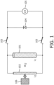
- Fig. 1 is an electric circuit diagram of an example of the superconducting magnet assembly 100 of the invention with the power supply coupled to it.
- the field coil windings 101 of self-inductance L1 are for simplicity shown her as a single unit, but in practice are arranged as an assembly of several field coils.
- the switching coil 102 of self-inductance L2 is shown as a single unit, but in practice the switching coil may be arranged as an assembly of several switching coil(s).
- the switching coil 102 and the field coil together form a superconducting loop closed in itself. There is no need for the coil sections forming the switching coil to be physically grouped together in the magnet, where the interconnecting wiring of the coil sections has to be such that all sections of the switching coil are connected directly in series, without elements of the non-switching category in between.
- a power supply is connected across the switching coil by means of electrically and thermally detachable leads 103, which may be remotely operated relays.
- the field coil 101 and the switching coil 102 may be cooled to superconducting temperature by a cryogenic system (not shown). It is advantageous to provide a means to increase the thermal resistance and/or reduce the refrigeration power for the switching coils during the time they have to be in the resistive state.
- the controllable power source 105 is connected to the current leads 103.
- a diode or stack of diodes 104 may be circuited in parallel to the power source 105 to allow electrical current from the magnet to circulate even when the power supply is in its switched off state.
Landscapes
- Physics & Mathematics (AREA)
- Engineering & Computer Science (AREA)
- Power Engineering (AREA)
- Electromagnetism (AREA)
- Condensed Matter Physics & Semiconductors (AREA)
- General Physics & Mathematics (AREA)
- Magnetic Resonance Imaging Apparatus (AREA)
- Containers, Films, And Cooling For Superconductive Devices (AREA)
Claims (10)
- Supraleitende Magnetanordnung, umfassend- eine Feldspulenanordnung, die (i) Spulenwicklungen mit Feldspulenwicklungen (101), die, wenn sie in Betrieb sind, elektrisch supraleitend sind, und (ii) Verbindungsanschlüsse (103) für eine Spannungsversorgung (105) aufweist,
wobei die Spulenwicklungen der Feldspulenanordnung zwischen den Verbindungsanschlüssen geschaltet sind,- und ein Schaltmodul (106), um einen Unterabschnitt (102) der Spulenwicklungen der Feldspulenanordnung zwischen ihrem elektrischen supraleitenden und ihrem elektrischen Widerstandszustand zu schalten, wobei der Unterabschnitt (102) eine Schaltspule (102) bildet, die zwischen den Verbindungsanschlüssen (103) parallel zu den Feldspulenwicklungen (101) geschaltet ist,dadurch gekennzeichnet, dass die Feldspulenwicklungen (101) und die Schaltspule (102) geometrisch koaxial entlang einer gemeinsamen Längsachse ausgerichtet sind, während Feldspulenwicklungen (101), sowie die Schaltspule (102) azimutal um die Längsachse herum liegen. - Supraleitende Magnetanordnung nach Anspruch 1, wobei die Induktivität der Schaltspule kleiner als die Induktivität der Feldspulenanordnung ist.
- Supraleitende Magnetanordnung nach einem der vorstehenden Ansprüche und die eine Trägerstruktur umfasst, welche die Feldspulenanordnung trägt, wobei zwischen der Schaltspule und der Trägerstruktur eine thermische Isolierung bereitgestellt ist.
- Supraleitende Magnetanordnung nach einem der vorstehenden Ansprüche, wobei in der Feldspulenanordnung die Schaltspule, wenn sie sich in ihrem supraleitenden Zustand befindet, mit den Feldspulenwicklungen in Reihe geschaltet ist.
- Supraleitende Magnetanordnung nach Anspruch 2, wobei das Verhältnis der Induktivität der Schaltspule zu der Induktivität der Feldspulenanordnung im Bereich von 1/20 bis ½, vorzugsweise im Bereich von (0,08 bis 0,12) liegt.
- Supraleitende Magnetanordnung nach einem der vorstehenden Ansprüche, wobei die Feldspulenwicklungen der Feldspulenanordnung und die Schaltspule Wicklungen aus einem supraleitenden Hochtemperatur-Material beinhalten, dessen kritische Temperatur im Bereich von 20-80K liegt.
- Supraleitende Magnetanordnung nach Anspruch 6, wobei das supraleitende Hochtemperatur-Material MgB2 ist.
- Supraleitende Magnetanordnung nach Anspruch 7, wobei die Schaltspule eine Länge an supraleitendem Draht in dem Bereich von 1600-2400m beinhaltet.
- Magnetresonanzuntersuchungssystem, das eine supraleitende Magnetanordnung nach einem der Ansprüche 1 bis 8 umfasst.
- Verfahren zum Hochfahren einer Feldspulenanordnung einer supraleitenden Magnetanordnung nach einem der Ansprüche 1 bis 8, wobei das Verfahren die Schritte umfasst zum- Einstellen der Schaltspule auf ihren Widerstandszustand und Verbinden einer Spannungsquelle mit den Verbindungsanschlüssen;- wenn der elektrische Strom durch die Feldspulenwicklungen seinen voreingestellten Endwert erreicht hat, Einstellen der Schaltspule auf ihren supraleitenden Zustand und- Abschalten der Spannungsquelle.
Applications Claiming Priority (2)
| Application Number | Priority Date | Filing Date | Title |
|---|---|---|---|
| EP17201479.7A EP3483902A1 (de) | 2017-11-14 | 2017-11-14 | Supraleitende magnetanordnung |
| PCT/EP2018/079527 WO2019096567A1 (en) | 2017-11-14 | 2018-10-29 | Superconducting magnet assembly |
Publications (2)
| Publication Number | Publication Date |
|---|---|
| EP3711072A1 EP3711072A1 (de) | 2020-09-23 |
| EP3711072B1 true EP3711072B1 (de) | 2024-07-10 |
Family
ID=60320761
Family Applications (2)
| Application Number | Title | Priority Date | Filing Date |
|---|---|---|---|
| EP17201479.7A Withdrawn EP3483902A1 (de) | 2017-11-14 | 2017-11-14 | Supraleitende magnetanordnung |
| EP18795523.2A Active EP3711072B1 (de) | 2017-11-14 | 2018-10-29 | Supraleitende magnetanordnung |
Family Applications Before (1)
| Application Number | Title | Priority Date | Filing Date |
|---|---|---|---|
| EP17201479.7A Withdrawn EP3483902A1 (de) | 2017-11-14 | 2017-11-14 | Supraleitende magnetanordnung |
Country Status (6)
| Country | Link |
|---|---|
| US (1) | US11404191B2 (de) |
| EP (2) | EP3483902A1 (de) |
| JP (1) | JP7266595B2 (de) |
| CN (1) | CN111433868B (de) |
| BR (1) | BR112020009355A2 (de) |
| WO (1) | WO2019096567A1 (de) |
Families Citing this family (4)
| Publication number | Priority date | Publication date | Assignee | Title |
|---|---|---|---|---|
| KR102715485B1 (ko) * | 2018-11-22 | 2024-10-11 | 토카막 에너지 리미티드 | 부분적으로 절연된 초전도 자석의 빠른 덤프 |
| EP4068311B1 (de) * | 2021-03-30 | 2024-02-28 | Bruker Switzerland AG | Verfahren zum laden und/oder entladen und/oder zur ladungsumkehr eines supraleitenden schalterfreien supraleitenden geschlossenen stromkreises durch gleichstromeinspeisung, supraleitender schalterfreier supraleitender geschlossener stromkreis zur verwendung mit diesem verfahren, supraleitender magnet und verfahren zur herstellung des supraleitenden stromkreises |
| EP4470355B1 (de) | 2022-01-27 | 2025-09-03 | Koninklijke Philips N.V. | Dauerstromschalter für einen supraleitenden elektromagneten |
| JP2023180128A (ja) * | 2022-06-08 | 2023-12-20 | 株式会社東芝 | 超電導マグネット装置及びその励磁方法 |
Citations (1)
| Publication number | Priority date | Publication date | Assignee | Title |
|---|---|---|---|---|
| CN107123504A (zh) * | 2017-07-03 | 2017-09-01 | 上海联影医疗科技有限公司 | 磁共振磁体降场系统及降场方法 |
Family Cites Families (27)
| Publication number | Priority date | Publication date | Assignee | Title |
|---|---|---|---|---|
| US3559128A (en) * | 1968-07-22 | 1971-01-26 | Varian Associates | Superconducting magnet for persistent operation |
| US4535291A (en) * | 1982-08-09 | 1985-08-13 | Varian Associates, Inc. | Method for superconducting magnet shimming |
| JPS61171105A (ja) * | 1985-01-25 | 1986-08-01 | Mitsubishi Electric Corp | 超電導マグネツトの励磁装置 |
| US4943792A (en) | 1988-02-25 | 1990-07-24 | General Electric Company | Superconducting switch pack |
| JPH0793206B2 (ja) * | 1990-03-02 | 1995-10-09 | 株式会社日立製作所 | 超電導磁界発生装置,超電導コイル及びその製造法 |
| JP2983323B2 (ja) * | 1991-03-29 | 1999-11-29 | 株式会社日立製作所 | 超電導磁石装置およびその運転方法 |
| JP2951459B2 (ja) * | 1991-11-20 | 1999-09-20 | 古河電気工業株式会社 | 超電導マグネット用電源装置 |
| JPH05327043A (ja) * | 1992-05-20 | 1993-12-10 | Hitachi Ltd | 超電導マグネット装置 |
| JPH0697516A (ja) * | 1992-09-11 | 1994-04-08 | Hitachi Ltd | 超電導エネルギー貯蔵装置 |
| US5426366A (en) * | 1992-12-11 | 1995-06-20 | U.S. Philips Corporation | Magnetic resonance apparatus comprising a superconducting magnet |
| JPH07115016A (ja) * | 1993-10-15 | 1995-05-02 | Hitachi Ltd | 超電導装置 |
| JPH10247753A (ja) * | 1997-03-05 | 1998-09-14 | Toshiba Corp | 超電導装置および超電導装置の制御方法 |
| US6014069A (en) | 1998-12-18 | 2000-01-11 | Havens; Timothy John | Superconducting magnet correction coil adjustment mechanism |
| JP2004179413A (ja) * | 2002-11-27 | 2004-06-24 | Mitsubishi Electric Corp | 冷却型超電導磁石装置 |
| US6960914B2 (en) * | 2003-06-27 | 2005-11-01 | Ge Medical Systems Global Technology Company, Llc | Methods and apparatus for imaging systems |
| US8384504B2 (en) * | 2006-01-06 | 2013-02-26 | Quantum Design International, Inc. | Superconducting quick switch |
| JP2008226501A (ja) * | 2007-03-08 | 2008-09-25 | Hitachi Ltd | MgB2超電導線材 |
| JP5366391B2 (ja) * | 2007-11-28 | 2013-12-11 | 三菱電機株式会社 | 超電導素子 |
| JP5017310B2 (ja) * | 2009-03-31 | 2012-09-05 | 株式会社日立製作所 | 永久電流スイッチ及び超電導マグネット |
| JP5603297B2 (ja) * | 2011-07-04 | 2014-10-08 | 株式会社日立製作所 | 超電導マグネット及びその製造方法 |
| US8922308B2 (en) | 2011-10-31 | 2014-12-30 | General Electric Company | Systems and methods for alternatingly switching a persistent current switch between a first mode and a second mode |
| WO2013114233A1 (en) | 2012-02-01 | 2013-08-08 | Koninklijke Philips N.V. | Automatic current switching of current leads for superconducting magnets |
| KR101351586B1 (ko) * | 2012-03-12 | 2014-01-15 | 삼성전자주식회사 | 영구 스위치 제어 시스템, 이를 채용한 초전도 자석 장치 및 영구 스위치 제어 방법 |
| JP5889116B2 (ja) * | 2012-06-11 | 2016-03-22 | 株式会社日立製作所 | MgB2超電導線材およびその製造方法 |
| US9638774B2 (en) * | 2013-08-05 | 2017-05-02 | Shahin Pourrahimi | Discharge controlled superconducting magnet |
| US10121955B2 (en) | 2013-12-20 | 2018-11-06 | Hitachi, Ltd. | Superconducting magnet, MRI, and NMR |
| WO2015177667A2 (en) * | 2014-05-21 | 2015-11-26 | Koninklijke Philips N.V. | Superconducting coil support device and method and apparatus including superconducting coil support device |
-
2017
- 2017-11-14 EP EP17201479.7A patent/EP3483902A1/de not_active Withdrawn
-
2018
- 2018-10-29 EP EP18795523.2A patent/EP3711072B1/de active Active
- 2018-10-29 WO PCT/EP2018/079527 patent/WO2019096567A1/en not_active Ceased
- 2018-10-29 JP JP2020526122A patent/JP7266595B2/ja active Active
- 2018-10-29 US US16/762,359 patent/US11404191B2/en active Active
- 2018-10-29 BR BR112020009355-6A patent/BR112020009355A2/pt not_active IP Right Cessation
- 2018-10-29 CN CN201880073915.1A patent/CN111433868B/zh active Active
Patent Citations (1)
| Publication number | Priority date | Publication date | Assignee | Title |
|---|---|---|---|---|
| CN107123504A (zh) * | 2017-07-03 | 2017-09-01 | 上海联影医疗科技有限公司 | 磁共振磁体降场系统及降场方法 |
Also Published As
| Publication number | Publication date |
|---|---|
| BR112020009355A2 (pt) | 2020-10-27 |
| CN111433868B (zh) | 2023-02-17 |
| JP2021503175A (ja) | 2021-02-04 |
| EP3483902A1 (de) | 2019-05-15 |
| WO2019096567A1 (en) | 2019-05-23 |
| US20200273611A1 (en) | 2020-08-27 |
| JP7266595B2 (ja) | 2023-04-28 |
| RU2020119335A3 (de) | 2022-03-24 |
| CN111433868A (zh) | 2020-07-17 |
| EP3711072A1 (de) | 2020-09-23 |
| US11404191B2 (en) | 2022-08-02 |
| RU2020119335A (ru) | 2021-12-15 |
Similar Documents
| Publication | Publication Date | Title |
|---|---|---|
| US8134434B2 (en) | Superconducting quick switch | |
| CN101366093B (zh) | 超导快速开关 | |
| EP3711072B1 (de) | Supraleitende magnetanordnung | |
| JP4295189B2 (ja) | 超伝導抵抗型限流器 | |
| Tixador et al. | First tests of a 800 kJ HTS SMES | |
| US6507259B2 (en) | Actively shielded superconducting magnet with protection means | |
| US11527343B2 (en) | Method for charging a superconductor magnet system, with a main superconductor bulk magnet and a shield superconductor bulk magnet | |
| US4812796A (en) | Quench propagation device for a superconducting magnet | |
| US20240155951A1 (en) | Superconducting magnet device, nmr device, and mri device | |
| RU2782553C2 (ru) | Узел сверхпроводящего магнита | |
| US20230097465A1 (en) | Emergency Shutdown of A No-Insulation Magnet | |
| US20250292938A1 (en) | Rapid dump of superconductor magnets | |
| JP7752779B2 (ja) | 超電導磁石用の磁石永久電流スイッチ | |
| US7646571B2 (en) | Circuit for effective quench heating in superconducting magnets | |
| US20180205223A1 (en) | Current Limiter Device Having A Coil And A Switch | |
| US20250279231A1 (en) | Superconducting magnet device | |
| CN119742717A (zh) | 一种极高场混合磁体失超保护系统及方法 |
Legal Events
| Date | Code | Title | Description |
|---|---|---|---|
| STAA | Information on the status of an ep patent application or granted ep patent |
Free format text: STATUS: UNKNOWN |
|
| STAA | Information on the status of an ep patent application or granted ep patent |
Free format text: STATUS: THE INTERNATIONAL PUBLICATION HAS BEEN MADE |
|
| PUAI | Public reference made under article 153(3) epc to a published international application that has entered the european phase |
Free format text: ORIGINAL CODE: 0009012 |
|
| STAA | Information on the status of an ep patent application or granted ep patent |
Free format text: STATUS: REQUEST FOR EXAMINATION WAS MADE |
|
| 17P | Request for examination filed |
Effective date: 20200615 |
|
| AK | Designated contracting states |
Kind code of ref document: A1 Designated state(s): AL AT BE BG CH CY CZ DE DK EE ES FI FR GB GR HR HU IE IS IT LI LT LU LV MC MK MT NL NO PL PT RO RS SE SI SK SM TR |
|
| AX | Request for extension of the european patent |
Extension state: BA ME |
|
| DAV | Request for validation of the european patent (deleted) | ||
| DAX | Request for extension of the european patent (deleted) | ||
| STAA | Information on the status of an ep patent application or granted ep patent |
Free format text: STATUS: EXAMINATION IS IN PROGRESS |
|
| 17Q | First examination report despatched |
Effective date: 20211008 |
|
| GRAP | Despatch of communication of intention to grant a patent |
Free format text: ORIGINAL CODE: EPIDOSNIGR1 |
|
| STAA | Information on the status of an ep patent application or granted ep patent |
Free format text: STATUS: GRANT OF PATENT IS INTENDED |
|
| INTG | Intention to grant announced |
Effective date: 20240318 |
|
| RIN1 | Information on inventor provided before grant (corrected) |
Inventor name: OVERWEG, JOHANNES ADRIANUS |
|
| GRAS | Grant fee paid |
Free format text: ORIGINAL CODE: EPIDOSNIGR3 |
|
| GRAA | (expected) grant |
Free format text: ORIGINAL CODE: 0009210 |
|
| STAA | Information on the status of an ep patent application or granted ep patent |
Free format text: STATUS: THE PATENT HAS BEEN GRANTED |
|
| AK | Designated contracting states |
Kind code of ref document: B1 Designated state(s): AL AT BE BG CH CY CZ DE DK EE ES FI FR GB GR HR HU IE IS IT LI LT LU LV MC MK MT NL NO PL PT RO RS SE SI SK SM TR |
|
| REG | Reference to a national code |
Ref country code: CH Ref legal event code: EP |
|
| REG | Reference to a national code |
Ref country code: DE Ref legal event code: R096 Ref document number: 602018071616 Country of ref document: DE |
|
| REG | Reference to a national code |
Ref country code: DE Ref legal event code: R084 Ref document number: 602018071616 Country of ref document: DE |
|
| REG | Reference to a national code |
Ref country code: LT Ref legal event code: MG9D |
|
| REG | Reference to a national code |
Ref country code: NL Ref legal event code: MP Effective date: 20240710 |
|
| PG25 | Lapsed in a contracting state [announced via postgrant information from national office to epo] |
Ref country code: PT Free format text: LAPSE BECAUSE OF FAILURE TO SUBMIT A TRANSLATION OF THE DESCRIPTION OR TO PAY THE FEE WITHIN THE PRESCRIBED TIME-LIMIT Effective date: 20241111 |
|
| REG | Reference to a national code |
Ref country code: AT Ref legal event code: MK05 Ref document number: 1702791 Country of ref document: AT Kind code of ref document: T Effective date: 20240710 |
|
| PG25 | Lapsed in a contracting state [announced via postgrant information from national office to epo] |
Ref country code: NL Free format text: LAPSE BECAUSE OF FAILURE TO SUBMIT A TRANSLATION OF THE DESCRIPTION OR TO PAY THE FEE WITHIN THE PRESCRIBED TIME-LIMIT Effective date: 20240710 |
|
| PG25 | Lapsed in a contracting state [announced via postgrant information from national office to epo] |
Ref country code: PT Free format text: LAPSE BECAUSE OF FAILURE TO SUBMIT A TRANSLATION OF THE DESCRIPTION OR TO PAY THE FEE WITHIN THE PRESCRIBED TIME-LIMIT Effective date: 20241111 Ref country code: NL Free format text: LAPSE BECAUSE OF FAILURE TO SUBMIT A TRANSLATION OF THE DESCRIPTION OR TO PAY THE FEE WITHIN THE PRESCRIBED TIME-LIMIT Effective date: 20240710 |
|
| PG25 | Lapsed in a contracting state [announced via postgrant information from national office to epo] |
Ref country code: NO Free format text: LAPSE BECAUSE OF FAILURE TO SUBMIT A TRANSLATION OF THE DESCRIPTION OR TO PAY THE FEE WITHIN THE PRESCRIBED TIME-LIMIT Effective date: 20241010 |
|
| REG | Reference to a national code |
Ref country code: GB Ref legal event code: 746 Effective date: 20241219 |
|
| PG25 | Lapsed in a contracting state [announced via postgrant information from national office to epo] |
Ref country code: FI Free format text: LAPSE BECAUSE OF FAILURE TO SUBMIT A TRANSLATION OF THE DESCRIPTION OR TO PAY THE FEE WITHIN THE PRESCRIBED TIME-LIMIT Effective date: 20240710 Ref country code: GR Free format text: LAPSE BECAUSE OF FAILURE TO SUBMIT A TRANSLATION OF THE DESCRIPTION OR TO PAY THE FEE WITHIN THE PRESCRIBED TIME-LIMIT Effective date: 20241011 Ref country code: PL Free format text: LAPSE BECAUSE OF FAILURE TO SUBMIT A TRANSLATION OF THE DESCRIPTION OR TO PAY THE FEE WITHIN THE PRESCRIBED TIME-LIMIT Effective date: 20240710 |
|
| PG25 | Lapsed in a contracting state [announced via postgrant information from national office to epo] |
Ref country code: BG Free format text: LAPSE BECAUSE OF FAILURE TO SUBMIT A TRANSLATION OF THE DESCRIPTION OR TO PAY THE FEE WITHIN THE PRESCRIBED TIME-LIMIT Effective date: 20240710 |
|
| PG25 | Lapsed in a contracting state [announced via postgrant information from national office to epo] |
Ref country code: LV Free format text: LAPSE BECAUSE OF FAILURE TO SUBMIT A TRANSLATION OF THE DESCRIPTION OR TO PAY THE FEE WITHIN THE PRESCRIBED TIME-LIMIT Effective date: 20240710 |
|
| PG25 | Lapsed in a contracting state [announced via postgrant information from national office to epo] |
Ref country code: IS Free format text: LAPSE BECAUSE OF FAILURE TO SUBMIT A TRANSLATION OF THE DESCRIPTION OR TO PAY THE FEE WITHIN THE PRESCRIBED TIME-LIMIT Effective date: 20241110 Ref country code: AT Free format text: LAPSE BECAUSE OF FAILURE TO SUBMIT A TRANSLATION OF THE DESCRIPTION OR TO PAY THE FEE WITHIN THE PRESCRIBED TIME-LIMIT Effective date: 20240710 |
|
| PG25 | Lapsed in a contracting state [announced via postgrant information from national office to epo] |
Ref country code: HR Free format text: LAPSE BECAUSE OF FAILURE TO SUBMIT A TRANSLATION OF THE DESCRIPTION OR TO PAY THE FEE WITHIN THE PRESCRIBED TIME-LIMIT Effective date: 20240710 |
|
| PG25 | Lapsed in a contracting state [announced via postgrant information from national office to epo] |
Ref country code: ES Free format text: LAPSE BECAUSE OF FAILURE TO SUBMIT A TRANSLATION OF THE DESCRIPTION OR TO PAY THE FEE WITHIN THE PRESCRIBED TIME-LIMIT Effective date: 20240710 Ref country code: RS Free format text: LAPSE BECAUSE OF FAILURE TO SUBMIT A TRANSLATION OF THE DESCRIPTION OR TO PAY THE FEE WITHIN THE PRESCRIBED TIME-LIMIT Effective date: 20241010 |
|
| PG25 | Lapsed in a contracting state [announced via postgrant information from national office to epo] |
Ref country code: RS Free format text: LAPSE BECAUSE OF FAILURE TO SUBMIT A TRANSLATION OF THE DESCRIPTION OR TO PAY THE FEE WITHIN THE PRESCRIBED TIME-LIMIT Effective date: 20241010 Ref country code: PL Free format text: LAPSE BECAUSE OF FAILURE TO SUBMIT A TRANSLATION OF THE DESCRIPTION OR TO PAY THE FEE WITHIN THE PRESCRIBED TIME-LIMIT Effective date: 20240710 Ref country code: NO Free format text: LAPSE BECAUSE OF FAILURE TO SUBMIT A TRANSLATION OF THE DESCRIPTION OR TO PAY THE FEE WITHIN THE PRESCRIBED TIME-LIMIT Effective date: 20241010 Ref country code: LV Free format text: LAPSE BECAUSE OF FAILURE TO SUBMIT A TRANSLATION OF THE DESCRIPTION OR TO PAY THE FEE WITHIN THE PRESCRIBED TIME-LIMIT Effective date: 20240710 Ref country code: IS Free format text: LAPSE BECAUSE OF FAILURE TO SUBMIT A TRANSLATION OF THE DESCRIPTION OR TO PAY THE FEE WITHIN THE PRESCRIBED TIME-LIMIT Effective date: 20241110 Ref country code: HR Free format text: LAPSE BECAUSE OF FAILURE TO SUBMIT A TRANSLATION OF THE DESCRIPTION OR TO PAY THE FEE WITHIN THE PRESCRIBED TIME-LIMIT Effective date: 20240710 Ref country code: GR Free format text: LAPSE BECAUSE OF FAILURE TO SUBMIT A TRANSLATION OF THE DESCRIPTION OR TO PAY THE FEE WITHIN THE PRESCRIBED TIME-LIMIT Effective date: 20241011 Ref country code: FI Free format text: LAPSE BECAUSE OF FAILURE TO SUBMIT A TRANSLATION OF THE DESCRIPTION OR TO PAY THE FEE WITHIN THE PRESCRIBED TIME-LIMIT Effective date: 20240710 Ref country code: ES Free format text: LAPSE BECAUSE OF FAILURE TO SUBMIT A TRANSLATION OF THE DESCRIPTION OR TO PAY THE FEE WITHIN THE PRESCRIBED TIME-LIMIT Effective date: 20240710 Ref country code: BG Free format text: LAPSE BECAUSE OF FAILURE TO SUBMIT A TRANSLATION OF THE DESCRIPTION OR TO PAY THE FEE WITHIN THE PRESCRIBED TIME-LIMIT Effective date: 20240710 Ref country code: AT Free format text: LAPSE BECAUSE OF FAILURE TO SUBMIT A TRANSLATION OF THE DESCRIPTION OR TO PAY THE FEE WITHIN THE PRESCRIBED TIME-LIMIT Effective date: 20240710 |
|
| REG | Reference to a national code |
Ref country code: DE Ref legal event code: R097 Ref document number: 602018071616 Country of ref document: DE |
|
| PG25 | Lapsed in a contracting state [announced via postgrant information from national office to epo] |
Ref country code: SM Free format text: LAPSE BECAUSE OF FAILURE TO SUBMIT A TRANSLATION OF THE DESCRIPTION OR TO PAY THE FEE WITHIN THE PRESCRIBED TIME-LIMIT Effective date: 20240710 Ref country code: DK Free format text: LAPSE BECAUSE OF FAILURE TO SUBMIT A TRANSLATION OF THE DESCRIPTION OR TO PAY THE FEE WITHIN THE PRESCRIBED TIME-LIMIT Effective date: 20240710 Ref country code: RO Free format text: LAPSE BECAUSE OF FAILURE TO SUBMIT A TRANSLATION OF THE DESCRIPTION OR TO PAY THE FEE WITHIN THE PRESCRIBED TIME-LIMIT Effective date: 20240710 |
|
| PG25 | Lapsed in a contracting state [announced via postgrant information from national office to epo] |
Ref country code: EE Free format text: LAPSE BECAUSE OF FAILURE TO SUBMIT A TRANSLATION OF THE DESCRIPTION OR TO PAY THE FEE WITHIN THE PRESCRIBED TIME-LIMIT Effective date: 20240710 |
|
| PG25 | Lapsed in a contracting state [announced via postgrant information from national office to epo] |
Ref country code: CZ Free format text: LAPSE BECAUSE OF FAILURE TO SUBMIT A TRANSLATION OF THE DESCRIPTION OR TO PAY THE FEE WITHIN THE PRESCRIBED TIME-LIMIT Effective date: 20240710 |
|
| PG25 | Lapsed in a contracting state [announced via postgrant information from national office to epo] |
Ref country code: SK Free format text: LAPSE BECAUSE OF FAILURE TO SUBMIT A TRANSLATION OF THE DESCRIPTION OR TO PAY THE FEE WITHIN THE PRESCRIBED TIME-LIMIT Effective date: 20240710 Ref country code: IT Free format text: LAPSE BECAUSE OF FAILURE TO SUBMIT A TRANSLATION OF THE DESCRIPTION OR TO PAY THE FEE WITHIN THE PRESCRIBED TIME-LIMIT Effective date: 20240710 |
|
| PLBE | No opposition filed within time limit |
Free format text: ORIGINAL CODE: 0009261 |
|
| STAA | Information on the status of an ep patent application or granted ep patent |
Free format text: STATUS: NO OPPOSITION FILED WITHIN TIME LIMIT |
|
| REG | Reference to a national code |
Ref country code: CH Ref legal event code: PL |
|
| 26N | No opposition filed |
Effective date: 20250411 |
|
| PG25 | Lapsed in a contracting state [announced via postgrant information from national office to epo] |
Ref country code: MC Free format text: LAPSE BECAUSE OF FAILURE TO SUBMIT A TRANSLATION OF THE DESCRIPTION OR TO PAY THE FEE WITHIN THE PRESCRIBED TIME-LIMIT Effective date: 20240710 |
|
| PG25 | Lapsed in a contracting state [announced via postgrant information from national office to epo] |
Ref country code: BE Free format text: LAPSE BECAUSE OF NON-PAYMENT OF DUE FEES Effective date: 20241031 Ref country code: LU Free format text: LAPSE BECAUSE OF NON-PAYMENT OF DUE FEES Effective date: 20241029 |
|
| PG25 | Lapsed in a contracting state [announced via postgrant information from national office to epo] |
Ref country code: FR Free format text: LAPSE BECAUSE OF NON-PAYMENT OF DUE FEES Effective date: 20241031 |
|
| PG25 | Lapsed in a contracting state [announced via postgrant information from national office to epo] |
Ref country code: CH Free format text: LAPSE BECAUSE OF NON-PAYMENT OF DUE FEES Effective date: 20241031 |
|
| REG | Reference to a national code |
Ref country code: BE Ref legal event code: MM Effective date: 20241031 |
|
| PG25 | Lapsed in a contracting state [announced via postgrant information from national office to epo] |
Ref country code: SE Free format text: LAPSE BECAUSE OF FAILURE TO SUBMIT A TRANSLATION OF THE DESCRIPTION OR TO PAY THE FEE WITHIN THE PRESCRIBED TIME-LIMIT Effective date: 20240710 |
|
| PG25 | Lapsed in a contracting state [announced via postgrant information from national office to epo] |
Ref country code: IE Free format text: LAPSE BECAUSE OF NON-PAYMENT OF DUE FEES Effective date: 20241029 |
|
| PGFP | Annual fee paid to national office [announced via postgrant information from national office to epo] |
Ref country code: DE Payment date: 20251028 Year of fee payment: 8 |
|
| PGFP | Annual fee paid to national office [announced via postgrant information from national office to epo] |
Ref country code: GB Payment date: 20251023 Year of fee payment: 8 |
|
| PG25 | Lapsed in a contracting state [announced via postgrant information from national office to epo] |
Ref country code: HU Free format text: LAPSE BECAUSE OF FAILURE TO SUBMIT A TRANSLATION OF THE DESCRIPTION OR TO PAY THE FEE WITHIN THE PRESCRIBED TIME-LIMIT; INVALID AB INITIO Effective date: 20181029 |
|
| PG25 | Lapsed in a contracting state [announced via postgrant information from national office to epo] |
Ref country code: CY Free format text: LAPSE BECAUSE OF FAILURE TO SUBMIT A TRANSLATION OF THE DESCRIPTION OR TO PAY THE FEE WITHIN THE PRESCRIBED TIME-LIMIT; INVALID AB INITIO Effective date: 20181029 |