EP3710311B1 - Interior assembly for supporting loads that is arranged in the upper interior part of the vehicle - Google Patents
Interior assembly for supporting loads that is arranged in the upper interior part of the vehicle Download PDFInfo
- Publication number
- EP3710311B1 EP3710311B1 EP18789423.3A EP18789423A EP3710311B1 EP 3710311 B1 EP3710311 B1 EP 3710311B1 EP 18789423 A EP18789423 A EP 18789423A EP 3710311 B1 EP3710311 B1 EP 3710311B1
- Authority
- EP
- European Patent Office
- Prior art keywords
- gallery
- vehicle
- galleries
- assembly
- link rod
- Prior art date
- Legal status (The legal status is an assumption and is not a legal conclusion. Google has not performed a legal analysis and makes no representation as to the accuracy of the status listed.)
- Active
Links
- 230000008878 coupling Effects 0.000 claims description 15
- 238000010168 coupling process Methods 0.000 claims description 15
- 238000005859 coupling reaction Methods 0.000 claims description 15
- 238000006073 displacement reaction Methods 0.000 claims description 5
- 230000001360 synchronised effect Effects 0.000 description 6
- 238000005192 partition Methods 0.000 description 4
- 239000002184 metal Substances 0.000 description 2
- 239000004743 Polypropylene Substances 0.000 description 1
- 238000010586 diagram Methods 0.000 description 1
- 238000009434 installation Methods 0.000 description 1
- 239000004033 plastic Substances 0.000 description 1
- -1 polypropylene Polymers 0.000 description 1
- 229920001155 polypropylene Polymers 0.000 description 1
Images

Classifications
-
- B—PERFORMING OPERATIONS; TRANSPORTING
- B60—VEHICLES IN GENERAL
- B60R—VEHICLES, VEHICLE FITTINGS, OR VEHICLE PARTS, NOT OTHERWISE PROVIDED FOR
- B60R5/00—Compartments within vehicle body primarily intended or sufficiently spacious for trunks, suit-cases, or the like
- B60R5/006—Compartments within vehicle body primarily intended or sufficiently spacious for trunks, suit-cases, or the like stowing or holding means for elongated articles, e.g. skis inside vehicles
-
- B—PERFORMING OPERATIONS; TRANSPORTING
- B60—VEHICLES IN GENERAL
- B60R—VEHICLES, VEHICLE FITTINGS, OR VEHICLE PARTS, NOT OTHERWISE PROVIDED FOR
- B60R7/00—Stowing or holding appliances inside vehicle primarily intended for personal property smaller than suit-cases, e.g. travelling articles, or maps
- B60R7/04—Stowing or holding appliances inside vehicle primarily intended for personal property smaller than suit-cases, e.g. travelling articles, or maps in driver or passenger space, e.g. using racks
-
- B—PERFORMING OPERATIONS; TRANSPORTING
- B60—VEHICLES IN GENERAL
- B60R—VEHICLES, VEHICLE FITTINGS, OR VEHICLE PARTS, NOT OTHERWISE PROVIDED FOR
- B60R7/00—Stowing or holding appliances inside vehicle primarily intended for personal property smaller than suit-cases, e.g. travelling articles, or maps
- B60R7/08—Disposition of racks, clips, holders, containers or the like for supporting specific articles
Definitions
- the present invention relates to an interior load-bearing assembly, being arranged in the upper interior part of a vehicle.
- a loading device made with at least one transverse bar supporting an object.
- Said bar is secured to the side walls of the vehicle body by securing at each of its ends to an L-shaped fixing foot comprising an opening and being fixed to the receiving vehicle wall using a male L-shaped fixing element the end of which is screwed a tightening knob to lock the position of the foot and therefore the position of the bar.
- the bar can be moved to the non-use position by pivoting 180 degrees towards the roof of the vehicle by loosening the knob, the bar is rotated manually by rotating the support leg, then the knob is tightened to lock the position.
- the device may comprise two bars, for example one above the driver's head and the other at the rear, above the neck of the rear passengers.
- the invention aims in particular to solve the drawbacks mentioned above by proposing a new interior load-bearing assembly for a vehicle.
- the invention proposes an interior load support assembly for a vehicle comprising the characteristics of claim 1.
- Said galleries thus form a retractable structure in the vehicle by maneuvering only one gallery, their movements by pivoting from a position of use to a position of non-use being synchronized.
- said first gallery comprises a device for locking its use and non-use positions.
- said first gallery comprises a locking device, because it is unnecessary for said second gallery to be equipped with a locking device of its own, its use and non-use positions being blocked by the locking device of the first gallery, due to the coupling between them.
- the first gallery forms the master gallery and the second gallery forms a slave gallery.
- the coupling means between said galleries comprise a first rod and a second rod hinged together at one of their respective ends, said first rod being hinged at its other end with said first gallery and said second rod being articulated at its other end with said second gallery.
- the first rod is longer than the second rod.
- At least one of the securing devices of the first roof rack inside the vehicle incorporates said means for locking the use and non-use positions.
- said gallery comprises a transverse bar extended at each of its ends by a lateral arm equipped with a push button
- said securing means comprise a guiding and locking device in the form sector having a groove for guiding the head of the pusher, said groove being in the form of an arc of a circle which has at each end a recessed housing receiving the head of the pusher and corresponding respectively to the position of use and non-use of the gallery.
- said galleries are pivotally mounted to be moved by pivoting, reversibly, from a position of use to a position of non-use following an angular displacement of 90 degrees.
- said assembly comprises a storage element extending from the galleries, in the form of a box comprising a substantially horizontal lower wall and extends into an upper wall which substantially matches the interior shape of the roof of the vehicle.
- the invention also relates to a motor vehicle, in particular a utility vehicle equipped with an interior load-bearing assembly. More specifically, the invention relates to a utility vehicle comprising, in its upper interior part, an interior load support assembly as defined previously, the roof racks being installed in the utility part of the vehicle, close to the feet and foot crosspieces of the vehicle. Said galleries retract in the non-use position in the space occupied by the foot crosspieces.
- the first gallery ie the master gallery
- the storage element of said assembly is arranged as an extension of the galleries in the upper part of the passenger compartment.
- said storage element is fixed between two foot crosspieces of the vehicle.
- X is the longitudinal front-rear direction of the vehicle, oriented towards the rear
- Y is the transverse direction oriented towards the right of the vehicle
- Z is the vertical direction oriented towards the top of the vehicle.
- the figure 1 schematically illustrates an interior assembly of load bearing elements according to the invention, installed in the upper part, ie under the roof T (or roof) of a utility motor vehicle.
- a load L supported by said assembly is represented in the form of a long object.
- This set includes a first gallery 1 corresponding to the rear gallery and a second gallery 2 corresponding to the front gallery.
- Each gallery is preferably arranged close to the upper crosspieces of the feet of the vehicle, this zone being a reinforced zone.
- the diagram does not show here the means of coupling between the galleries, the galleries and their coupling being illustrated in more detail in figures 2A to 2C and to figures 3 and 4 commented below.
- feet B, C, D of the vehicle (the first foot further forward not being visible in this figure) and a partition W separating the passenger compartment from the utility part of the vehicle.
- These feet which have the function of consolidating the structure of the vehicle by linking the part of the sill, i.e. substantially at the level of the floor P, to the part of the roof T of the vehicle, rise vertically in the form of an "I". and have extensions at their ends in the form of crosspieces at the bottom of the body, and also in the form of crosspieces TB, TC, TD at the bottom of the flag.
- This set further comprises a storage box 3 located at the front of the vehicle, high up in the passenger compartment, above the passenger seat S according to this particular case, and at the front of a partition W arranged between the passenger compartment and the utility part.
- a storage box 3 located at the front of the vehicle, high up in the passenger compartment, above the passenger seat S according to this particular case, and at the front of a partition W arranged between the passenger compartment and the utility part.
- An example of such a storage box is described in more detail at the support of the figure 5 .
- This safe can be optional according to the invention, but preferably it is integrated into the assembly according to the invention.
- the figures 2A to 2C schematically illustrate the coupling of the rear 1 and front 2 galleries when the galleries pass from the low position of use to a high position of non-use, according to an angular displacement of 90 degrees.
- the figure 2A schematically illustrates the two galleries in the low position according to a side view
- the figure 2B schematically illustrates the two galleries in an intermediate position between the low position and the high position, following a three-quarter volume view from the side and from below
- the Fig. 2C schematically illustrates the two galleries in a high position, following a side view.
- the rear gallery 1 is the master gallery of the coupling of the galleries and the front gallery 2 is the gallery slaved to said master gallery.
- An example of the front roof rack 2 is illustrated in picture 3 and an example of a rear gallery 1 is illustrated (partially) in figure 4 .
- the picture 3 illustrates an example of a front gallery 2 mounted between the side walls C1, C2, of the body structure, at the top of the vehicle, close to the foot cross member TC.
- Said gallery consists of a transverse bar 220 adapted to the width of the vehicle, extended integrally at one of its ends by a first vertical side bar 221 and at its opposite end by a second vertical side bar 222.
- Such gallery can be for example a U-shaped bent metal tube.
- said crossbar 220 receives the loads, and the vertical bars make it possible to retain the loads laterally while forming the support arms of the crossbar and receivers of the means of attachment to the vehicle.
- Each vertical bar 221, 222 is provided at its upper end with a support 240, 250 for securing to the body wall which is provided with a transverse pivot axis allowing the pivoting of said gallery around said pivot axis, reversibly, for the move from a low position, corresponding to the use position, to a raised position, following an angular displacement of approximately 90 degrees from the low position, and corresponding to the non-use position.
- Each securing support interfaces between the roof rack and a body wall.
- the supports can be simple supports.
- the support could for example be a support mounted articulated on the body wall with position locking means.
- the roof rack comprises a device for securing to a side wall of the vehicle, making the roof rack pivotable and incorporating a locking/unlocking mechanism for the positions of use and non-use of the roof rack.
- the gallery 1 is formed of a bent tube comprising a rectilinear transverse part, forming the transverse bar receiving the loads and extended at each end, at the level of the curvature of the tube, by vertical arms 12 which are secured at their respective end to the side walls of the vehicle body.
- the roof rack is illustrated, partially, in the lowered position and in the raised position at 90 degrees.
- the securing means comprise a mounting lug 40 having a through hole and to which is added a guide and locking device 41 in the form of a sector.
- Said device 41 comprises an axis hole which comes into correspondence with the orifice of the bracket and through which passes a bolt 42 (or screw), and said bolt having been previously inserted into a hole drilled in the tubular arm 12 of the gallery.
- Said sector-shaped guide and locking device 41 also has a guide groove 410, in the shape of an arc of a circle, which guides the head of a spring-loaded pusher 43 fixed through the tubular arm of the gallery, the spring being on the opposite side to the sector shape and placed in abutment against a plate 44 fixed to said arm.
- the head of the pusher is located at the opposite end to that surrounded by the spring, and is on the side of said guide groove 410.
- Said groove comprises at each end a recessed housing in which the head of the pusher is housed, the housings corresponding respectively at the low position and at the raised position of the gallery. The housings are thus positioned at the end of travel of the angular displacements of the gallery in the longitudinal directions X+ or X-.
- the spring of the pusher compresses under this push so that the head of the pusher comes out of its housing at the end of the guide groove of the sector to then be guided along the arc of said groove until it reaches the other housing, the spring relaxes and the head is then held by the force of the relaxed spring in said other housing.
- the two lower and raised positions of the roof rack can thus be locked.
- the roof racks are mounted according to the representations illustrated respectively in figures 3 and 4 .
- the galleries are joined together by an articulated coupling device 50 in order to make their movements in rotation synchronous and thus put them simultaneously in the position of non-use, the figures 2A to 2C showing the progress of the move.
- the rear gallery 1 which is the main gallery, is mounted at the end of at least one of its arms 12 on a device for securing to the body wall incorporating a guide device and locking such as the sector-shaped device 41 cooperating with the push button 43 on the arm of the gallery.
- said gallery is connected at said arm 12 to an articulated coupling device 50.
- Said coupling device 50 comprises a first rod 510 and a second rod 520 which are connected at one of their ends to each other. in an articulated manner on a transverse axis of rotation, the other end of the first rod 510 being connected by articulation on an axis of rotation to an arm 12 of the rear gallery 1, and the end of the second rod being connected to a arm 222 of the front gallery 2, on the same side as the connected arm of the master gallery 1, at a point one higher than that of connection between the first rod and the rear gallery.
- the first rod 510 connected to the rear and main gallery 1 is longer than the second rod 520 connected to the front gallery 2.
- the gallery pivots by guiding in the guide groove 410 of its guiding and locking device 41 towards its raised position, at 90 degrees from its low position of use.
- the first rod 510 of the coupling device transmits the rotational movement imparted on the rear roof rack 1 causes the second rod of the coupling device to tilt, which will then push the front roof rack 2, the latter pivoting in turn following its mounting device on the box wall.
- the two galleries are thus in the raised position, horizontally, at the same time, according to a synchronized movement, the operator having only to act on one of the galleries, according to the example on the rear gallery 1
- the force thus exerted unlocks the position of the gallery 1 and the coupling device 50 then drives the front roof rack 2 to rotate it from the horizontal plane to the vertical plane.
- An advantage of the invention is that the roof racks can be folded up in the vehicle without having to disassemble them or store them, and that their positioning for non-use is done in a single maneuver, and the same for their positioning 'use.
- the device is easy to implement by a user thanks to the locking system integrated into the securing supports.
- Another advantage of the invention is the installation of the roof racks in the upper part of the vehicle, close to the feet and the foot crosspieces, so that the roof racks in the non-use position, that is to say raised at horizontal, occupy the space between the foot rails which is a space not usually used.
- the non-use gallery structure thus occupies a dead volume of the vehicle, and does not create additional space.
- the feet and foot crosspieces that reinforce the body structure can be sized according to the use of the vehicle and the weight of the loads that the vehicle is authorized to transport.
- the galleries that is to say to have two galleries abutting one another in the same direction, i.e. the transverse direction of the vehicle, supported by a central support to which the sides of said two abutting roof racks are attached to separate the deployment of the roof racks on the right side of the vehicle from those on the left side.
- said central support is common to said two galleries, said support integrating a pivot axis making it possible to move said two abutting galleries by pivoting.
- Said central support of the galleries is preferably fixed on the body structure, in a zone substantially centered on the foot crosspieces.
- the galleries are also on their other side secured to a side wall of the vehicle, for example according to the modes described above.
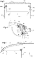
- FIG 5 is illustrated an example of a load-bearing front element 3 of said interior load-bearing assembly, which is arranged as an extension of the galleries which have just been described, this arrangement taking place in particular in the passenger compartment above one or more passengers.
- This front load support element 3 is a box which makes it possible to transport, and if necessary to store, objects above the head of the passenger and/or the driver.
- This box can be preformed in plastic, for example in polypropylene.
- This box-shaped element comprises a lower wall 30 which is preferably horizontal and extends into an upper wall 31 which substantially matches the internal shape of the pavilion.
- this box-shaped element In front of this box-shaped element is a set of indexing pins 61 which participate in the centering (indexing) of the box on the roof crosspiece TP.
- a metal insert 60 making it possible to stiffen said element.
- This insert also makes it possible to fix the partition W between the passenger compartment and the utility part of the vehicle, said partition being lower than for a vehicle not equipped with the storage unit.
- a flat zone 62 which makes it possible to fix said element on the foot crosspiece TB. Isostatism is thus ensured.
- This box-shaped element thus advantageously extends the galleries for transporting and storing objects.
Description
La présente invention se rapporte à un ensemble intérieur support de charges, se disposant en partie intérieure haute d'un véhicule.The present invention relates to an interior load-bearing assembly, being arranged in the upper interior part of a vehicle.
Il existe un besoin de pouvoir installer des charges, et notamment des charges longues, à l'intérieur d'un véhicule particulier ou utilitaire pour pouvoir les transporter, voire les stocker, tout en ayant les portes fermées.There is a need to be able to install loads, and in particular long loads, inside a private or utility vehicle in order to be able to transport them, or even store them, while having the doors closed.
Il a été proposé d'utiliser l'espace intérieur de la zone pavillonnaire du véhicule, soit sous le toit, en y installant une galerie intérieure pour y charger des objets.It was proposed to use the interior space of the vehicle's pavilion area, ie under the roof, by installing an interior gallery there to load objects.
Ainsi dans la demande de brevet
Il peut cependant être fastidieux d'avoir à pivoter chaque barre support de charge. De plus l'aménagement de l'espace pavillonnaire intérieur du véhicule peut être mieux optimisé.However, it can be tedious to have to pivot each load support bar. In addition, the layout of the interior pavilion space of the vehicle can be better optimized.
Le document
L'invention vise notamment à résoudre les inconvénients évoqués ci-dessus en proposant un nouvel ensemble intérieur support de charges d'un véhicule.The invention aims in particular to solve the drawbacks mentioned above by proposing a new interior load-bearing assembly for a vehicle.
A cet effet, l'invention propose un ensemble intérieur support de charges d'un véhicule comportant les caractéristiques de la revendication 1.To this end, the invention proposes an interior load support assembly for a vehicle comprising the characteristics of
Lesdites galeries forment ainsi une structure escamotable dans le véhicule en ne manœuvrant qu'une seule galerie, leurs déplacements par pivotement d'une position d'usage à une position de non-usage étant synchronisés.Said galleries thus form a retractable structure in the vehicle by maneuvering only one gallery, their movements by pivoting from a position of use to a position of non-use being synchronized.
De préférence ladite première galerie comprend un dispositif de verrouillage de ses positions d'usage et de non usage. Avantageusement seule ladite première galerie comprend un dispositif de verrouillage, car il est inutile que ladite deuxième galerie soit équipée d'un dispositif de verrouillage qui lui est propre, ses positions d'usage et de non usage étant bloquées par le dispositif de verrouillage de la première galerie, du fait du couplage entre elles. En d'autres termes la première galerie forme la galerie maîtresse et la deuxième galerie forme une galerie asservie.Preferably, said first gallery comprises a device for locking its use and non-use positions. Advantageously only said first gallery comprises a locking device, because it is unnecessary for said second gallery to be equipped with a locking device of its own, its use and non-use positions being blocked by the locking device of the first gallery, due to the coupling between them. In other words, the first gallery forms the master gallery and the second gallery forms a slave gallery.
Conformément à l'invention, les moyens de couplage entre lesdites galeries comprennent une première tringle et une deuxième tringle articulées entre elles en l'une de leur extrémité respective, ladite première tringle étant articulée en son autre extrémité avec ladite première galerie et ladite deuxième tringle étant articulée en son autre extrémité avec ladite deuxième galerie.According to the invention, the coupling means between said galleries comprise a first rod and a second rod hinged together at one of their respective ends, said first rod being hinged at its other end with said first gallery and said second rod being articulated at its other end with said second gallery.
Avantageusement selon l'invention, la première tringle est d'une longueur supérieure à la deuxième tringle.Advantageously according to the invention, the first rod is longer than the second rod.
Selon un mode de réalisation particulier de l'invention, au moins l'un des dispositifs de solidarisation de la première galerie à l'intérieur du véhicule intègre lesdits moyens de verrouillage des positions d'usage et de non-usage.According to a particular embodiment of the invention, at least one of the securing devices of the first roof rack inside the vehicle incorporates said means for locking the use and non-use positions.
Selon un mode de réalisation particulier de l'invention, ladite galerie comprend une barre transversale prolongée en chacune de ses extrémités d'un bras latéral équipé d'un bouton poussoir, et lesdits moyens de solidarisation comprennent un dispositif de guidage et de verrouillage en forme de secteur présentant une rainure de guidage de la tête du poussoir, ladite rainure étant en forme d'un arc de cercle qui présente en chaque extrémité un logement en creux récepteur de la tête du poussoir et correspondant respectivement à la position d'usage et de non-usage de la galerie.According to a particular embodiment of the invention, said gallery comprises a transverse bar extended at each of its ends by a lateral arm equipped with a push button, and said securing means comprise a guiding and locking device in the form sector having a groove for guiding the head of the pusher, said groove being in the form of an arc of a circle which has at each end a recessed housing receiving the head of the pusher and corresponding respectively to the position of use and non-use of the gallery.
De préférence selon l'invention, lesdites galeries sont montées pivotables pour être déplacées par pivotement, réversiblement, d'une position d'usage à une position de non-usage suivant un déplacement angulaire de 90 degrés.Preferably according to the invention, said galleries are pivotally mounted to be moved by pivoting, reversibly, from a position of use to a position of non-use following an angular displacement of 90 degrees.
Avantageusement selon l'invention, ledit ensemble comprend un élément de rangement en prolongement des galeries, se présentant sous forme d'une boîte comportant une paroi inférieure sensiblement horizontale et se prolonge en une paroi supérieure qui épouse sensiblement la forme intérieure du pavillon du véhicule.Advantageously according to the invention, said assembly comprises a storage element extending from the galleries, in the form of a box comprising a substantially horizontal lower wall and extends into an upper wall which substantially matches the interior shape of the roof of the vehicle.
L'invention concerne aussi un véhicule automobile, en particulier un véhicule utilitaire équipé d'un ensemble intérieur support de charges. Plus spécifiquement, l'invention concerne un véhicule utilitaire comprenant dans sa partie intérieure haute, un ensemble intérieur support de charges tel que défini précédemment, les galeries étant installées en partie utilitaire du véhicule, à proximité des pieds et traverses de pieds du véhicule. Lesdites galeries s'escamotent en position de non-usage dans l'espace occupé par les traverses de pieds.The invention also relates to a motor vehicle, in particular a utility vehicle equipped with an interior load-bearing assembly. More specifically, the invention relates to a utility vehicle comprising, in its upper interior part, an interior load support assembly as defined previously, the roof racks being installed in the utility part of the vehicle, close to the feet and foot crosspieces of the vehicle. Said galleries retract in the non-use position in the space occupied by the foot crosspieces.
De préférence selon l'invention, la première galerie, soit la galerie maîtresse, est la galerie située le plus à l'arrière du véhicule.Preferably according to the invention, the first gallery, ie the master gallery, is the gallery located furthest to the rear of the vehicle.
De préférence selon l'invention, l'élément de rangement dudit ensemble est aménagé en prolongement des galeries dans la partie haute de l'habitacle.Preferably according to the invention, the storage element of said assembly is arranged as an extension of the galleries in the upper part of the passenger compartment.
Avantageusement selon l'invention, ledit élément de rangement est fixé entre deux traverses de pieds du véhicule.Advantageously according to the invention, said storage element is fixed between two foot crosspieces of the vehicle.
D'autres particularités et avantages de l'invention ressortiront à la lecture de la description faite ci-après d'un mode de réalisation particulier de l'invention, à titre indicatif mais non limitatif, en référence aux dessins annexés pour lesquels :
- la
figure 1 illustre schématiquement; un ensemble intérieur support de charges selon l'invention, installé dans un véhicule automobile utilitaire, suivant une vue en coupe longitudinale ; - la
figure 2A illustre schématiquement deux galeries supports de charges synchronisées, qui sont des éléments supports de charges dudit ensemble, en position basse suivant une vue de côté des galeries ; - la
figure 2B illustre schématiquement les deux galeries synchronisées de lafigure 2A , dans une position intermédiaire entre la position basse et la position haute, suivant une vue en volume de trois-quarts de côté et de dessous; - la
figure 2C illustre schématiquement les deux galeries synchronisées de lafigure 2A ou 2B , en position haute, suivant une vue de côté ; - la
figure 3 illustre schématiquement un mode de réalisation d'une des galeries desfigures 2A à 2C , munie d'un support de solidarisation à la caisse du véhicule, suivant une vue de face avant, soit suivant une vue transversale du véhicule; - la
figure 4 illustre schématiquement un mode de réalisation d'une galerie des galeries représentées auxfigures 2A à 2C , munie d'un support de solidarisation et de verrouillage à la caisse du véhicule, suivant une vue en perspective de l'intérieur vers un côté ; - la
figure 5 illustre schématiquement; un mode de réalisation d'un élément avant d'un ensemble intérieur support de charges tel que celui de lafigure 1 , suivant une vue en coupe longitudinale du véhicule.
- the
figure 1 schematically illustrates; an interior load support assembly according to the invention, installed in a utility motor vehicle, in a longitudinal section view; - the
figure 2A schematically illustrates two synchronized load support galleries, which are load support elements of said assembly, in the low position according to a side view of the galleries; - the
figure 2B schematically illustrates the two synchronized galleries of thefigure 2A , in an intermediate position between the low position and the high position, in a three-quarter volume view from the side and from below; - the
Fig. 2C schematically illustrates the two synchronized galleries of thefigure 2A or 2B , in the high position, according to a side view; - the
picture 3figures 2A to 2C , provided with a support for securing to the body of the vehicle, according to a front face view, or according to a transverse view of the vehicle; - the
figure 4 schematically illustrates one embodiment of a gallery of the galleries shown infigures 2A to 2C , provided with a support for securing and locking the body of the vehicle, according to a perspective view from the inside towards one side; - the
figure 5 schematically illustrates; an embodiment of a front element of an interior load-carrying assembly such as that of thefigure 1 , according to a view in longitudinal section of the vehicle.
Dans la suite de la description, il est fait référence à un repère XYZ, dans lequel X est la direction longitudinale avant-arrière du véhicule, orientée vers l'arrière, Y est la direction transversale orientée vers la droite du véhicule, et Z est la direction verticale orientée vers le haut du véhicule.In the remainder of the description, reference is made to a reference XYZ, in which X is the longitudinal front-rear direction of the vehicle, oriented towards the rear, Y is the transverse direction oriented towards the right of the vehicle, and Z is the vertical direction oriented towards the top of the vehicle.
La
Cet ensemble comprend une première galerie 1 correspondant à la galerie arrière et une deuxième galerie 2 correspondant à la galerie avant. Chaque galerie est disposée de préférence à proximité des traverses supérieures des pieds du véhicule, cette zone étant une zone renforcée. Le schéma ne montre pas ici les moyens de couplage entre les galeries, les galeries et leur couplage étant illustrés plus en détails aux
Sur cette
Cet ensemble comprend en outre un coffre de rangement 3 situé à l'avant du véhicule, en hauteur dans l'habitacle, au-dessus du siège S du passager selon ce cas particulier, et à l'avant d'une cloison de séparation W disposée entre l'habitacle et la partie utilitaire. Un exemple d'un tel coffre de rangement est décrit plus en détails à l'appui de la
Les
La galerie arrière 1 est la galerie maitresse du couplage des galeries et la galerie avant 2 est la galerie asservie à ladite galerie maîtresse. Un exemple de réalisation de galerie avant 2 est illustré en
La
Cette galerie avant 2 n'étant pas de préférence verrouillable dans ses positions d'usage et de non-usage, les supports peuvent être des supports simples. Au cas où un verrouillage/déverrouillage serait envisagé, le support pourrait par exemple être un support monté articulé sur la paroi de caisse avec des moyens de blocage de positions.This
Suivant la
Concernant le couplage des galeries avant 2 et arrière 1, les galeries sont montées selon les représentations illustrées respectivement aux
Un avantage de l'invention est que les galeries peuvent être repliées dans le véhicule sans avoir à les démonter ni stocker, et que leur mise en position de non-usage se fait en une seule manœuvre, et de même pour leur mise en position d'usage. Le dispositif est facile à mettre en œuvre par un utilisateur grâce au système de verrouillage intégré aux supports de solidarisation.An advantage of the invention is that the roof racks can be folded up in the vehicle without having to disassemble them or store them, and that their positioning for non-use is done in a single maneuver, and the same for their positioning 'use. The device is easy to implement by a user thanks to the locking system integrated into the securing supports.
Un autre avantage de l'invention est l'installation des galeries en partie haute du véhicule, à proximité des pieds et des traverses de pied, de sorte que les galeries en position de non-usage, c'est-à-dire relevées à l'horizontal, occupent l'espace entre les traverses de pied qui est un espace non utilisé habituellement. La structure de galerie en non-usage occupe ainsi un volume mort du véhicule, et ne crée pas un encombrement supplémentaire. De plus les pieds et traverses de pieds qui renforcent la structure de caisse peuvent être dimensionnés selon l'usage du véhicule et du poids des charges que le véhicule est autorisé à transporter.Another advantage of the invention is the installation of the roof racks in the upper part of the vehicle, close to the feet and the foot crosspieces, so that the roof racks in the non-use position, that is to say raised at horizontal, occupy the space between the foot rails which is a space not usually used. The non-use gallery structure thus occupies a dead volume of the vehicle, and does not create additional space. In addition, the feet and foot crosspieces that reinforce the body structure can be sized according to the use of the vehicle and the weight of the loads that the vehicle is authorized to transport.
De plus, selon un cas non illustré, il est possible de fractionner les galeries, c'est-à-dire d'avoir deux galeries aboutées l'une à l'autre suivant la même direction, soit la direction transversale du véhicule, supportées par un support central auquel se fixent les côtés desdites deux galeries aboutées pour dissocier le déploiement des galeries côté droit du véhicule de celles du côté gauche. De préférence ledit support central est commun aux dites deux galeries, ledit support intégrant un axe de pivot permettant de déplacer par pivotement lesdites deux galeries aboutées. Ledit support central des galeries se fixe de préférence sur la structure de caisse, dans une zone sensiblement centré sur les traverses de pied. Les galeries sont par ailleurs de leur autre côté solidarisées à une paroi latérale du véhicule, par exemple selon les modes décrits précédemment.In addition, according to a case not shown, it is possible to split the galleries, that is to say to have two galleries abutting one another in the same direction, i.e. the transverse direction of the vehicle, supported by a central support to which the sides of said two abutting roof racks are attached to separate the deployment of the roof racks on the right side of the vehicle from those on the left side. Preferably, said central support is common to said two galleries, said support integrating a pivot axis making it possible to move said two abutting galleries by pivoting. Said central support of the galleries is preferably fixed on the body structure, in a zone substantially centered on the foot crosspieces. The galleries are also on their other side secured to a side wall of the vehicle, for example according to the modes described above.
En
En avant de cet élément en forme de boite se trouve un ensemble de pions d'indexage 61 qui participent au centrage (indexage) de la boite sur la traverse pavillon TP. A l'arrière de la paroi inférieure 30, se trouve un insert métallique 60 permettant de rigidifier ledit élément. Cet insert permet aussi de fixer la cloison W entre l'habitacle et la partie utilitaire du véhicule, ladite cloison étant moins haute que pour un véhicule non équipé de l'ensemble de rangement. A l'arrière de la paroi supérieure 31, se trouve une zone plane 62 qui permet de fixer ledit élément sur la traverse de pied TB. Ainsi l'isostatisme est assuré. On peut prévoir alternativement ou en complément des pions d'indexage, une traverse intermédiaire pour supporter le poids de l'élément et les objets stockés, la traverse étant reprise de part et d'autre du véhicule.In front of this box-shaped element is a set of indexing pins 61 which participate in the centering (indexing) of the box on the roof crosspiece TP. At the rear of the
Cet élément en forme de boîte prolonge ainsi avantageusement les galeries pour le transport et le stockage d'objets.This box-shaped element thus advantageously extends the galleries for transporting and storing objects.
Claims (11)
- Interior load support assembly arranged in the upper interior part of a vehicle, comprising at least a first and a second load support gallery (1, 2), these being provided with a device for securing inside the vehicle and mounted so as to be reversibly moved by pivoting from a position of use to a position of non-use, said galleries being secured to one another by coupling means (50) such that the movement of one of the galleries causes the other gallery to move when reversibly passing from a position of use to a position of non-use, characterized in that the coupling means (50) between said galleries comprise a first link rod (510) and a second link rod (520) that are articulated to one another at one of their respective ends, said first link rod being articulated at its other end to said first gallery and said second link rod being connected at its other end in a fixed manner to said second gallery.
- Assembly according to Claim 1, characterized in that said first gallery (1) comprises a device for locking its positions of use and of non-use.
- Assembly according to Claim 1, characterized in that the first link rod (510) is longer than the second link rod (520).
- Assembly according to one of Claims 1 to 3, characterized in that said means for locking the positions of use and of non-use are integrated into at least one of the devices for securing said first gallery to the interior of the vehicle.
- Assembly according to Claim 4, characterized in that said first gallery (1) comprises a transverse bar extended at each of its ends by a lateral arm (12) equipped with a pushbutton (43), and said securing means comprise a guiding and locking device (41) in the form of a sector having a slot (410) for guiding the head of the pushbutton (43), said slot being in the form of an arc of a circle which has, at each end, a hollow recess for receiving the head of the pushbutton and corresponding respectively to the position of use and of non-use of the gallery.
- Assembly according to one of Claims 1 to 5, characterized in that said galleries are mounted so as to be able to be pivoted in order to be reversibly moved by pivoting from a position of use to a position of non-use through an angular displacement of 90 degrees.
- Assembly according to one of Claims 1 to 6, characterized in that it comprises a storage element (3) in the extension of the galleries (1, 2), taking the form of a box comprising an essentially horizontal lower wall (30) and extending into an upper wall (31) which essentially matches the internal shape of the roof (T) of the vehicle.
- Utility vehicle, characterized in that it comprises, in its upper interior part, an interior load support assembly defined in one of Claims 1 to 7, the galleries (1, 2) of said assembly being installed in the utility portion of the vehicle, close to the pillars (C, D) and pillar crossmembers (TC, TD) of the vehicle.
- Utility vehicle according to Claim 8, characterized in that the first gallery (1) of said galleries is the gallery located furthest to the rear of the vehicle.
- Utility vehicle according to either of Claims 8 and 9, characterized in that the storage element (3) of said assembly is arranged in the extension of the galleries (1, 2), in the upper portion of the passenger compartment.
- Utility vehicle according to Claim 10, characterized in that said storage element is secured between two pillar crossmembers (TP, TB) of the vehicle.
Applications Claiming Priority (2)
| Application Number | Priority Date | Filing Date | Title |
|---|---|---|---|
| FR1760799A FR3073474B1 (en) | 2017-11-16 | 2017-11-16 | INTERNAL ASSEMBLY SUPPORT OF LOADS OF A VEHICLE |
| PCT/EP2018/079065 WO2019096550A1 (en) | 2017-11-16 | 2018-10-23 | Interior assembly for supporting loads that is arranged in the upper interior part of the vehicle |
Publications (2)
| Publication Number | Publication Date |
|---|---|
| EP3710311A1 EP3710311A1 (en) | 2020-09-23 |
| EP3710311B1 true EP3710311B1 (en) | 2022-04-27 |
Family
ID=60955272
Family Applications (1)
| Application Number | Title | Priority Date | Filing Date |
|---|---|---|---|
| EP18789423.3A Active EP3710311B1 (en) | 2017-11-16 | 2018-10-23 | Interior assembly for supporting loads that is arranged in the upper interior part of the vehicle |
Country Status (5)
| Country | Link |
|---|---|
| EP (1) | EP3710311B1 (en) |
| JP (1) | JP2021503407A (en) |
| CN (1) | CN111356612B (en) |
| FR (1) | FR3073474B1 (en) |
| WO (1) | WO2019096550A1 (en) |
Citations (1)
| Publication number | Priority date | Publication date | Assignee | Title |
|---|---|---|---|---|
| US3534892A (en) * | 1968-05-01 | 1970-10-20 | Edward L Truelove Sr | Utility rack for station wagons or the like |
Family Cites Families (8)
| Publication number | Priority date | Publication date | Assignee | Title |
|---|---|---|---|---|
| FR2682657B1 (en) * | 1991-10-21 | 1997-10-03 | Peugeot | ARRANGEMENT FOR THE TRANSPORT OF AN OBJECT OF LARGE LENGTH WITHIN A MOTOR VEHICLE. |
| JP2824047B2 (en) * | 1996-07-31 | 1998-11-11 | 西川化成株式会社 | Automotive roof carrier |
| FR2880599B1 (en) * | 2005-01-13 | 2008-12-26 | Wagon Sas | INTERIOR CARRIER DEVICE FOR MOTOR VEHICLE AND VEHICLE THEREFOR |
| ITTO20060667A1 (en) * | 2006-09-19 | 2008-03-20 | Fiat Auto Spa | SEAT-PARATIA GROUP, IN PARTICULAR FOR A COMMERCIAL VEHICLE, AND COMMERCIAL VEHICLE PROVIDED WITH THIS SEAT-PARATIA GROUP |
| GB2441989B (en) * | 2006-09-21 | 2011-09-07 | Ford Global Tech Llc | An overhead storage compartment for a vehicle |
| DE102007037212A1 (en) * | 2007-08-07 | 2009-02-12 | GM Global Technology Operations, Inc., Detroit | Motor vehicle, has cross bars fastened to motor vehicle under formation of openings between vehicle roof and respective cross bar, and oblong cargo fed through openings and supported on cross bars |
| FR2927031B1 (en) * | 2008-01-31 | 2010-06-04 | Peugeot Citroen Automobiles Sa | INTERIOR GALLERY |
| DE102014109698B3 (en) * | 2014-05-14 | 2015-10-22 | Webasto SE | Arrangement with a cover for a vehicle roof |
-
2017
- 2017-11-16 FR FR1760799A patent/FR3073474B1/en active Active
-
2018
- 2018-10-23 EP EP18789423.3A patent/EP3710311B1/en active Active
- 2018-10-23 JP JP2020526965A patent/JP2021503407A/en active Pending
- 2018-10-23 WO PCT/EP2018/079065 patent/WO2019096550A1/en unknown
- 2018-10-23 CN CN201880074285.XA patent/CN111356612B/en active Active
Patent Citations (1)
| Publication number | Priority date | Publication date | Assignee | Title |
|---|---|---|---|---|
| US3534892A (en) * | 1968-05-01 | 1970-10-20 | Edward L Truelove Sr | Utility rack for station wagons or the like |
Also Published As
| Publication number | Publication date |
|---|---|
| WO2019096550A1 (en) | 2019-05-23 |
| FR3073474A1 (en) | 2019-05-17 |
| CN111356612B (en) | 2023-09-19 |
| JP2021503407A (en) | 2021-02-12 |
| FR3073474B1 (en) | 2019-10-18 |
| EP3710311A1 (en) | 2020-09-23 |
| CN111356612A (en) | 2020-06-30 |
Similar Documents
| Publication | Publication Date | Title |
|---|---|---|
| EP1778524B1 (en) | Safety device for use in the event of a vehicle roll over | |
| FR2548106A1 (en) | AUXILIARY SEAT FOR VEHICLES | |
| FR2990167A1 (en) | SEAT, IN PARTICULAR FOR MOTOR VEHICLE | |
| FR3051416B1 (en) | DEVICE FOR SEPARATING BETWEEN A COCKPIT AND A LOADING SPACE AND VEHICLE EQUIPPED WITH SUCH A DEVICE | |
| FR2829082A1 (en) | Automobile rear transverse cycle carrier comprises two parallel arms, to which gutter shaped wheel support rails are fixed transversely, pivoting mounted at end about axis transverse to vehicle wing | |
| EP2285621B1 (en) | Arrangement for an automobile trunk and automobile including such an arrangement | |
| FR2632580A1 (en) | Device with retractable seats for vehicles | |
| FR3010018A1 (en) | ARRANGEMENT OF A SLIDING PARTITION WITHIN A VEHICLE WITH AN OPENING | |
| EP2048033A1 (en) | Retractable roof rack system for an automobile, controlled by a lever, and corresponding vehicle. | |
| EP3710311B1 (en) | Interior assembly for supporting loads that is arranged in the upper interior part of the vehicle | |
| EP3381753A1 (en) | Tilting buckle | |
| WO2004082972A1 (en) | Retractable roof for a vehicle | |
| EP1227004B1 (en) | Cargo carrying device with at least two positions for automotive vehicle | |
| FR2896207A1 (en) | Small dimension object or accessory storage parcel tray for fascia of e.g. four-door sedan, has mobile frame immobilization unit defining free space between frame and case`s upper side, where height of space varies for each stop position | |
| CA1158278A (en) | Inside arrangement of a vehicle such as a folding tent trailer | |
| EP1964712B1 (en) | Retractable seat for an automobile | |
| FR3021001A1 (en) | MOTOR VEHICLE HAVING RETRACTABLE SEAT SUPPORTS | |
| EP3888979B1 (en) | Retractable bike mount | |
| EP2184201A1 (en) | Adjustable seat for an automotive vehicle | |
| FR3024680A1 (en) | MOTOR VEHICLE SEAT AND MOTOR VEHICLE EQUIPPED WITH SUCH A SEAT | |
| FR3129643A1 (en) | Vehicle equipped with a modular storage space | |
| FR2843773A1 (en) | Hinge system for opening rear door of motor vehicle has pin that slides in guide rail to control initial opening movement | |
| EP3882082A1 (en) | Vehicle with improved pivoting arm | |
| FR3016835A1 (en) | AUTOMOTIVE VEHICLE BACK BENCH BACKREST | |
| FR3010019A1 (en) | ARRANGEMENT OF A SLIDING PARTITION WITHIN A VEHICLE COMPRISING AN OPENER WITH A PROTECTIVE MEANS |
Legal Events
| Date | Code | Title | Description |
|---|---|---|---|
| STAA | Information on the status of an ep patent application or granted ep patent |
Free format text: STATUS: UNKNOWN |
|
| STAA | Information on the status of an ep patent application or granted ep patent |
Free format text: STATUS: THE INTERNATIONAL PUBLICATION HAS BEEN MADE |
|
| PUAI | Public reference made under article 153(3) epc to a published international application that has entered the european phase |
Free format text: ORIGINAL CODE: 0009012 |
|
| STAA | Information on the status of an ep patent application or granted ep patent |
Free format text: STATUS: REQUEST FOR EXAMINATION WAS MADE |
|
| 17P | Request for examination filed |
Effective date: 20200504 |
|
| AK | Designated contracting states |
Kind code of ref document: A1 Designated state(s): AL AT BE BG CH CY CZ DE DK EE ES FI FR GB GR HR HU IE IS IT LI LT LU LV MC MK MT NL NO PL PT RO RS SE SI SK SM TR |
|
| AX | Request for extension of the european patent |
Extension state: BA ME |
|
| DAV | Request for validation of the european patent (deleted) | ||
| DAX | Request for extension of the european patent (deleted) | ||
| STAA | Information on the status of an ep patent application or granted ep patent |
Free format text: STATUS: EXAMINATION IS IN PROGRESS |
|
| 17Q | First examination report despatched |
Effective date: 20210416 |
|
| GRAP | Despatch of communication of intention to grant a patent |
Free format text: ORIGINAL CODE: EPIDOSNIGR1 |
|
| STAA | Information on the status of an ep patent application or granted ep patent |
Free format text: STATUS: GRANT OF PATENT IS INTENDED |
|
| INTG | Intention to grant announced |
Effective date: 20211122 |
|
| RAP3 | Party data changed (applicant data changed or rights of an application transferred) |
Owner name: RENAULT S.A.S |
|
| GRAS | Grant fee paid |
Free format text: ORIGINAL CODE: EPIDOSNIGR3 |
|
| GRAA | (expected) grant |
Free format text: ORIGINAL CODE: 0009210 |
|
| STAA | Information on the status of an ep patent application or granted ep patent |
Free format text: STATUS: THE PATENT HAS BEEN GRANTED |
|
| AK | Designated contracting states |
Kind code of ref document: B1 Designated state(s): AL AT BE BG CH CY CZ DE DK EE ES FI FR GB GR HR HU IE IS IT LI LT LU LV MC MK MT NL NO PL PT RO RS SE SI SK SM TR |
|
| REG | Reference to a national code |
Ref country code: GB Ref legal event code: FG4D Free format text: NOT ENGLISH |
|
| REG | Reference to a national code |
Ref country code: CH Ref legal event code: EP |
|
| REG | Reference to a national code |
Ref country code: AT Ref legal event code: REF Ref document number: 1486712 Country of ref document: AT Kind code of ref document: T Effective date: 20220515 |
|
| REG | Reference to a national code |
Ref country code: DE Ref legal event code: R096 Ref document number: 602018034593 Country of ref document: DE |
|
| REG | Reference to a national code |
Ref country code: IE Ref legal event code: FG4D Free format text: LANGUAGE OF EP DOCUMENT: FRENCH |
|
| RAP4 | Party data changed (patent owner data changed or rights of a patent transferred) |
Owner name: RENAULT S.A.S |
|
| REG | Reference to a national code |
Ref country code: LT Ref legal event code: MG9D |
|
| REG | Reference to a national code |
Ref country code: NL Ref legal event code: MP Effective date: 20220427 |
|
| REG | Reference to a national code |
Ref country code: AT Ref legal event code: MK05 Ref document number: 1486712 Country of ref document: AT Kind code of ref document: T Effective date: 20220427 |
|
| PG25 | Lapsed in a contracting state [announced via postgrant information from national office to epo] |
Ref country code: NL Free format text: LAPSE BECAUSE OF FAILURE TO SUBMIT A TRANSLATION OF THE DESCRIPTION OR TO PAY THE FEE WITHIN THE PRESCRIBED TIME-LIMIT Effective date: 20220427 |
|
| PG25 | Lapsed in a contracting state [announced via postgrant information from national office to epo] |
Ref country code: SE Free format text: LAPSE BECAUSE OF FAILURE TO SUBMIT A TRANSLATION OF THE DESCRIPTION OR TO PAY THE FEE WITHIN THE PRESCRIBED TIME-LIMIT Effective date: 20220427 Ref country code: PT Free format text: LAPSE BECAUSE OF FAILURE TO SUBMIT A TRANSLATION OF THE DESCRIPTION OR TO PAY THE FEE WITHIN THE PRESCRIBED TIME-LIMIT Effective date: 20220829 Ref country code: NO Free format text: LAPSE BECAUSE OF FAILURE TO SUBMIT A TRANSLATION OF THE DESCRIPTION OR TO PAY THE FEE WITHIN THE PRESCRIBED TIME-LIMIT Effective date: 20220727 Ref country code: LT Free format text: LAPSE BECAUSE OF FAILURE TO SUBMIT A TRANSLATION OF THE DESCRIPTION OR TO PAY THE FEE WITHIN THE PRESCRIBED TIME-LIMIT Effective date: 20220427 Ref country code: HR Free format text: LAPSE BECAUSE OF FAILURE TO SUBMIT A TRANSLATION OF THE DESCRIPTION OR TO PAY THE FEE WITHIN THE PRESCRIBED TIME-LIMIT Effective date: 20220427 Ref country code: GR Free format text: LAPSE BECAUSE OF FAILURE TO SUBMIT A TRANSLATION OF THE DESCRIPTION OR TO PAY THE FEE WITHIN THE PRESCRIBED TIME-LIMIT Effective date: 20220728 Ref country code: FI Free format text: LAPSE BECAUSE OF FAILURE TO SUBMIT A TRANSLATION OF THE DESCRIPTION OR TO PAY THE FEE WITHIN THE PRESCRIBED TIME-LIMIT Effective date: 20220427 Ref country code: ES Free format text: LAPSE BECAUSE OF FAILURE TO SUBMIT A TRANSLATION OF THE DESCRIPTION OR TO PAY THE FEE WITHIN THE PRESCRIBED TIME-LIMIT Effective date: 20220427 Ref country code: BG Free format text: LAPSE BECAUSE OF FAILURE TO SUBMIT A TRANSLATION OF THE DESCRIPTION OR TO PAY THE FEE WITHIN THE PRESCRIBED TIME-LIMIT Effective date: 20220727 Ref country code: AT Free format text: LAPSE BECAUSE OF FAILURE TO SUBMIT A TRANSLATION OF THE DESCRIPTION OR TO PAY THE FEE WITHIN THE PRESCRIBED TIME-LIMIT Effective date: 20220427 |
|
| PG25 | Lapsed in a contracting state [announced via postgrant information from national office to epo] |
Ref country code: RS Free format text: LAPSE BECAUSE OF FAILURE TO SUBMIT A TRANSLATION OF THE DESCRIPTION OR TO PAY THE FEE WITHIN THE PRESCRIBED TIME-LIMIT Effective date: 20220427 Ref country code: PL Free format text: LAPSE BECAUSE OF FAILURE TO SUBMIT A TRANSLATION OF THE DESCRIPTION OR TO PAY THE FEE WITHIN THE PRESCRIBED TIME-LIMIT Effective date: 20220427 Ref country code: LV Free format text: LAPSE BECAUSE OF FAILURE TO SUBMIT A TRANSLATION OF THE DESCRIPTION OR TO PAY THE FEE WITHIN THE PRESCRIBED TIME-LIMIT Effective date: 20220427 Ref country code: IS Free format text: LAPSE BECAUSE OF FAILURE TO SUBMIT A TRANSLATION OF THE DESCRIPTION OR TO PAY THE FEE WITHIN THE PRESCRIBED TIME-LIMIT Effective date: 20220827 |
|
| REG | Reference to a national code |
Ref country code: DE Ref legal event code: R097 Ref document number: 602018034593 Country of ref document: DE |
|
| PG25 | Lapsed in a contracting state [announced via postgrant information from national office to epo] |
Ref country code: SM Free format text: LAPSE BECAUSE OF FAILURE TO SUBMIT A TRANSLATION OF THE DESCRIPTION OR TO PAY THE FEE WITHIN THE PRESCRIBED TIME-LIMIT Effective date: 20220427 Ref country code: SK Free format text: LAPSE BECAUSE OF FAILURE TO SUBMIT A TRANSLATION OF THE DESCRIPTION OR TO PAY THE FEE WITHIN THE PRESCRIBED TIME-LIMIT Effective date: 20220427 Ref country code: RO Free format text: LAPSE BECAUSE OF FAILURE TO SUBMIT A TRANSLATION OF THE DESCRIPTION OR TO PAY THE FEE WITHIN THE PRESCRIBED TIME-LIMIT Effective date: 20220427 Ref country code: EE Free format text: LAPSE BECAUSE OF FAILURE TO SUBMIT A TRANSLATION OF THE DESCRIPTION OR TO PAY THE FEE WITHIN THE PRESCRIBED TIME-LIMIT Effective date: 20220427 Ref country code: DK Free format text: LAPSE BECAUSE OF FAILURE TO SUBMIT A TRANSLATION OF THE DESCRIPTION OR TO PAY THE FEE WITHIN THE PRESCRIBED TIME-LIMIT Effective date: 20220427 Ref country code: CZ Free format text: LAPSE BECAUSE OF FAILURE TO SUBMIT A TRANSLATION OF THE DESCRIPTION OR TO PAY THE FEE WITHIN THE PRESCRIBED TIME-LIMIT Effective date: 20220427 |
|
| PLBE | No opposition filed within time limit |
Free format text: ORIGINAL CODE: 0009261 |
|
| STAA | Information on the status of an ep patent application or granted ep patent |
Free format text: STATUS: NO OPPOSITION FILED WITHIN TIME LIMIT |
|
| PG25 | Lapsed in a contracting state [announced via postgrant information from national office to epo] |
Ref country code: AL Free format text: LAPSE BECAUSE OF FAILURE TO SUBMIT A TRANSLATION OF THE DESCRIPTION OR TO PAY THE FEE WITHIN THE PRESCRIBED TIME-LIMIT Effective date: 20220427 |
|
| 26N | No opposition filed |
Effective date: 20230130 |
|
| PG25 | Lapsed in a contracting state [announced via postgrant information from national office to epo] |
Ref country code: SI Free format text: LAPSE BECAUSE OF FAILURE TO SUBMIT A TRANSLATION OF THE DESCRIPTION OR TO PAY THE FEE WITHIN THE PRESCRIBED TIME-LIMIT Effective date: 20220427 Ref country code: MC Free format text: LAPSE BECAUSE OF FAILURE TO SUBMIT A TRANSLATION OF THE DESCRIPTION OR TO PAY THE FEE WITHIN THE PRESCRIBED TIME-LIMIT Effective date: 20220427 |
|
| REG | Reference to a national code |
Ref country code: CH Ref legal event code: PL |
|
| REG | Reference to a national code |
Ref country code: BE Ref legal event code: MM Effective date: 20221031 |
|
| PG25 | Lapsed in a contracting state [announced via postgrant information from national office to epo] |
Ref country code: LU Free format text: LAPSE BECAUSE OF NON-PAYMENT OF DUE FEES Effective date: 20221023 |
|
| P01 | Opt-out of the competence of the unified patent court (upc) registered |
Effective date: 20230608 |
|
| PG25 | Lapsed in a contracting state [announced via postgrant information from national office to epo] |
Ref country code: LI Free format text: LAPSE BECAUSE OF NON-PAYMENT OF DUE FEES Effective date: 20221031 Ref country code: CH Free format text: LAPSE BECAUSE OF NON-PAYMENT OF DUE FEES Effective date: 20221031 |
|
| PG25 | Lapsed in a contracting state [announced via postgrant information from national office to epo] |
Ref country code: BE Free format text: LAPSE BECAUSE OF NON-PAYMENT OF DUE FEES Effective date: 20221031 |
|
| PG25 | Lapsed in a contracting state [announced via postgrant information from national office to epo] |
Ref country code: IE Free format text: LAPSE BECAUSE OF NON-PAYMENT OF DUE FEES Effective date: 20221023 |
|
| PGFP | Annual fee paid to national office [announced via postgrant information from national office to epo] |
Ref country code: GB Payment date: 20231020 Year of fee payment: 6 |
|
| PG25 | Lapsed in a contracting state [announced via postgrant information from national office to epo] |
Ref country code: IT Free format text: LAPSE BECAUSE OF FAILURE TO SUBMIT A TRANSLATION OF THE DESCRIPTION OR TO PAY THE FEE WITHIN THE PRESCRIBED TIME-LIMIT Effective date: 20220427 |
|
| PGFP | Annual fee paid to national office [announced via postgrant information from national office to epo] |
Ref country code: FR Payment date: 20231026 Year of fee payment: 6 Ref country code: DE Payment date: 20231020 Year of fee payment: 6 |