EP3710300B1 - Procédé de contrôle d'un dispositif d'engagement d'une machine électrique de véhicule hybride, et véhicule automobile hybride - Google Patents
Procédé de contrôle d'un dispositif d'engagement d'une machine électrique de véhicule hybride, et véhicule automobile hybride Download PDFInfo
- Publication number
- EP3710300B1 EP3710300B1 EP18800246.3A EP18800246A EP3710300B1 EP 3710300 B1 EP3710300 B1 EP 3710300B1 EP 18800246 A EP18800246 A EP 18800246A EP 3710300 B1 EP3710300 B1 EP 3710300B1
- Authority
- EP
- European Patent Office
- Prior art keywords
- vehicle
- time delay
- temp
- engagement device
- speed threshold
- Prior art date
- Legal status (The legal status is an assumption and is not a legal conclusion. Google has not performed a legal analysis and makes no representation as to the accuracy of the status listed.)
- Active
Links
Images
Classifications
-
- B—PERFORMING OPERATIONS; TRANSPORTING
- B60—VEHICLES IN GENERAL
- B60K—ARRANGEMENT OR MOUNTING OF PROPULSION UNITS OR OF TRANSMISSIONS IN VEHICLES; ARRANGEMENT OR MOUNTING OF PLURAL DIVERSE PRIME-MOVERS IN VEHICLES; AUXILIARY DRIVES FOR VEHICLES; INSTRUMENTATION OR DASHBOARDS FOR VEHICLES; ARRANGEMENTS IN CONNECTION WITH COOLING, AIR INTAKE, GAS EXHAUST OR FUEL SUPPLY OF PROPULSION UNITS IN VEHICLES
- B60K6/00—Arrangement or mounting of plural diverse prime-movers for mutual or common propulsion, e.g. hybrid propulsion systems comprising electric motors and internal combustion engines
- B60K6/20—Arrangement or mounting of plural diverse prime-movers for mutual or common propulsion, e.g. hybrid propulsion systems comprising electric motors and internal combustion engines the prime-movers consisting of electric motors and internal combustion engines, e.g. HEVs
- B60K6/50—Architecture of the driveline characterised by arrangement or kind of transmission units
- B60K6/52—Driving a plurality of drive axles, e.g. four-wheel drive
-
- B—PERFORMING OPERATIONS; TRANSPORTING
- B60—VEHICLES IN GENERAL
- B60K—ARRANGEMENT OR MOUNTING OF PROPULSION UNITS OR OF TRANSMISSIONS IN VEHICLES; ARRANGEMENT OR MOUNTING OF PLURAL DIVERSE PRIME-MOVERS IN VEHICLES; AUXILIARY DRIVES FOR VEHICLES; INSTRUMENTATION OR DASHBOARDS FOR VEHICLES; ARRANGEMENTS IN CONNECTION WITH COOLING, AIR INTAKE, GAS EXHAUST OR FUEL SUPPLY OF PROPULSION UNITS IN VEHICLES
- B60K6/00—Arrangement or mounting of plural diverse prime-movers for mutual or common propulsion, e.g. hybrid propulsion systems comprising electric motors and internal combustion engines
- B60K6/20—Arrangement or mounting of plural diverse prime-movers for mutual or common propulsion, e.g. hybrid propulsion systems comprising electric motors and internal combustion engines the prime-movers consisting of electric motors and internal combustion engines, e.g. HEVs
- B60K6/22—Arrangement or mounting of plural diverse prime-movers for mutual or common propulsion, e.g. hybrid propulsion systems comprising electric motors and internal combustion engines the prime-movers consisting of electric motors and internal combustion engines, e.g. HEVs characterised by apparatus, components or means specially adapted for HEVs
- B60K6/38—Arrangement or mounting of plural diverse prime-movers for mutual or common propulsion, e.g. hybrid propulsion systems comprising electric motors and internal combustion engines the prime-movers consisting of electric motors and internal combustion engines, e.g. HEVs characterised by apparatus, components or means specially adapted for HEVs characterised by the driveline clutches
- B60K6/387—Actuated clutches, i.e. clutches engaged or disengaged by electric, hydraulic or mechanical actuating means
-
- B—PERFORMING OPERATIONS; TRANSPORTING
- B60—VEHICLES IN GENERAL
- B60W—CONJOINT CONTROL OF VEHICLE SUB-UNITS OF DIFFERENT TYPE OR DIFFERENT FUNCTION; CONTROL SYSTEMS SPECIALLY ADAPTED FOR HYBRID VEHICLES; ROAD VEHICLE DRIVE CONTROL SYSTEMS FOR PURPOSES NOT RELATED TO THE CONTROL OF A PARTICULAR SUB-UNIT
- B60W10/00—Conjoint control of vehicle sub-units of different type or different function
- B60W10/02—Conjoint control of vehicle sub-units of different type or different function including control of driveline clutches
-
- B—PERFORMING OPERATIONS; TRANSPORTING
- B60—VEHICLES IN GENERAL
- B60W—CONJOINT CONTROL OF VEHICLE SUB-UNITS OF DIFFERENT TYPE OR DIFFERENT FUNCTION; CONTROL SYSTEMS SPECIALLY ADAPTED FOR HYBRID VEHICLES; ROAD VEHICLE DRIVE CONTROL SYSTEMS FOR PURPOSES NOT RELATED TO THE CONTROL OF A PARTICULAR SUB-UNIT
- B60W20/00—Control systems specially adapted for hybrid vehicles
- B60W20/40—Controlling the engagement or disengagement of prime movers, e.g. for transition between prime movers
-
- B—PERFORMING OPERATIONS; TRANSPORTING
- B60—VEHICLES IN GENERAL
- B60W—CONJOINT CONTROL OF VEHICLE SUB-UNITS OF DIFFERENT TYPE OR DIFFERENT FUNCTION; CONTROL SYSTEMS SPECIALLY ADAPTED FOR HYBRID VEHICLES; ROAD VEHICLE DRIVE CONTROL SYSTEMS FOR PURPOSES NOT RELATED TO THE CONTROL OF A PARTICULAR SUB-UNIT
- B60W30/00—Purposes of road vehicle drive control systems not related to the control of a particular sub-unit, e.g. of systems using conjoint control of vehicle sub-units
- B60W30/18—Propelling the vehicle
- B60W30/18009—Propelling the vehicle related to particular drive situations
- B60W30/18054—Propelling the vehicle related to particular drive situations at stand still, e.g. engine in idling state
-
- B—PERFORMING OPERATIONS; TRANSPORTING
- B60—VEHICLES IN GENERAL
- B60W—CONJOINT CONTROL OF VEHICLE SUB-UNITS OF DIFFERENT TYPE OR DIFFERENT FUNCTION; CONTROL SYSTEMS SPECIALLY ADAPTED FOR HYBRID VEHICLES; ROAD VEHICLE DRIVE CONTROL SYSTEMS FOR PURPOSES NOT RELATED TO THE CONTROL OF A PARTICULAR SUB-UNIT
- B60W20/00—Control systems specially adapted for hybrid vehicles
-
- B—PERFORMING OPERATIONS; TRANSPORTING
- B60—VEHICLES IN GENERAL
- B60W—CONJOINT CONTROL OF VEHICLE SUB-UNITS OF DIFFERENT TYPE OR DIFFERENT FUNCTION; CONTROL SYSTEMS SPECIALLY ADAPTED FOR HYBRID VEHICLES; ROAD VEHICLE DRIVE CONTROL SYSTEMS FOR PURPOSES NOT RELATED TO THE CONTROL OF A PARTICULAR SUB-UNIT
- B60W50/00—Details of control systems for road vehicle drive control not related to the control of a particular sub-unit, e.g. process diagnostic or vehicle driver interfaces
- B60W2050/0001—Details of the control system
- B60W2050/0019—Control system elements or transfer functions
- B60W2050/0042—Transfer function lag; delays
-
- B—PERFORMING OPERATIONS; TRANSPORTING
- B60—VEHICLES IN GENERAL
- B60W—CONJOINT CONTROL OF VEHICLE SUB-UNITS OF DIFFERENT TYPE OR DIFFERENT FUNCTION; CONTROL SYSTEMS SPECIALLY ADAPTED FOR HYBRID VEHICLES; ROAD VEHICLE DRIVE CONTROL SYSTEMS FOR PURPOSES NOT RELATED TO THE CONTROL OF A PARTICULAR SUB-UNIT
- B60W50/00—Details of control systems for road vehicle drive control not related to the control of a particular sub-unit, e.g. process diagnostic or vehicle driver interfaces
- B60W2050/0062—Adapting control system settings
- B60W2050/0075—Automatic parameter input, automatic initialising or calibrating means
- B60W2050/0095—Automatic control mode change
- B60W2050/0096—Control during transition between modes
-
- B—PERFORMING OPERATIONS; TRANSPORTING
- B60—VEHICLES IN GENERAL
- B60W—CONJOINT CONTROL OF VEHICLE SUB-UNITS OF DIFFERENT TYPE OR DIFFERENT FUNCTION; CONTROL SYSTEMS SPECIALLY ADAPTED FOR HYBRID VEHICLES; ROAD VEHICLE DRIVE CONTROL SYSTEMS FOR PURPOSES NOT RELATED TO THE CONTROL OF A PARTICULAR SUB-UNIT
- B60W2510/00—Input parameters relating to a particular sub-units
- B60W2510/10—Change speed gearings
- B60W2510/107—Temperature
-
- B—PERFORMING OPERATIONS; TRANSPORTING
- B60—VEHICLES IN GENERAL
- B60W—CONJOINT CONTROL OF VEHICLE SUB-UNITS OF DIFFERENT TYPE OR DIFFERENT FUNCTION; CONTROL SYSTEMS SPECIALLY ADAPTED FOR HYBRID VEHICLES; ROAD VEHICLE DRIVE CONTROL SYSTEMS FOR PURPOSES NOT RELATED TO THE CONTROL OF A PARTICULAR SUB-UNIT
- B60W2520/00—Input parameters relating to overall vehicle dynamics
- B60W2520/10—Longitudinal speed
-
- B—PERFORMING OPERATIONS; TRANSPORTING
- B60—VEHICLES IN GENERAL
- B60W—CONJOINT CONTROL OF VEHICLE SUB-UNITS OF DIFFERENT TYPE OR DIFFERENT FUNCTION; CONTROL SYSTEMS SPECIALLY ADAPTED FOR HYBRID VEHICLES; ROAD VEHICLE DRIVE CONTROL SYSTEMS FOR PURPOSES NOT RELATED TO THE CONTROL OF A PARTICULAR SUB-UNIT
- B60W2540/00—Input parameters relating to occupants
- B60W2540/16—Ratio selector position
-
- B—PERFORMING OPERATIONS; TRANSPORTING
- B60—VEHICLES IN GENERAL
- B60W—CONJOINT CONTROL OF VEHICLE SUB-UNITS OF DIFFERENT TYPE OR DIFFERENT FUNCTION; CONTROL SYSTEMS SPECIALLY ADAPTED FOR HYBRID VEHICLES; ROAD VEHICLE DRIVE CONTROL SYSTEMS FOR PURPOSES NOT RELATED TO THE CONTROL OF A PARTICULAR SUB-UNIT
- B60W2552/00—Input parameters relating to infrastructure
- B60W2552/15—Road slope, i.e. the inclination of a road segment in the longitudinal direction
-
- B—PERFORMING OPERATIONS; TRANSPORTING
- B60—VEHICLES IN GENERAL
- B60W—CONJOINT CONTROL OF VEHICLE SUB-UNITS OF DIFFERENT TYPE OR DIFFERENT FUNCTION; CONTROL SYSTEMS SPECIALLY ADAPTED FOR HYBRID VEHICLES; ROAD VEHICLE DRIVE CONTROL SYSTEMS FOR PURPOSES NOT RELATED TO THE CONTROL OF A PARTICULAR SUB-UNIT
- B60W2555/00—Input parameters relating to exterior conditions, not covered by groups B60W2552/00, B60W2554/00
- B60W2555/40—Altitude
-
- B—PERFORMING OPERATIONS; TRANSPORTING
- B60—VEHICLES IN GENERAL
- B60W—CONJOINT CONTROL OF VEHICLE SUB-UNITS OF DIFFERENT TYPE OR DIFFERENT FUNCTION; CONTROL SYSTEMS SPECIALLY ADAPTED FOR HYBRID VEHICLES; ROAD VEHICLE DRIVE CONTROL SYSTEMS FOR PURPOSES NOT RELATED TO THE CONTROL OF A PARTICULAR SUB-UNIT
- B60W2710/00—Output or target parameters relating to a particular sub-units
- B60W2710/02—Clutches
- B60W2710/021—Clutch engagement state
-
- F—MECHANICAL ENGINEERING; LIGHTING; HEATING; WEAPONS; BLASTING
- F16—ENGINEERING ELEMENTS AND UNITS; GENERAL MEASURES FOR PRODUCING AND MAINTAINING EFFECTIVE FUNCTIONING OF MACHINES OR INSTALLATIONS; THERMAL INSULATION IN GENERAL
- F16H—GEARING
- F16H61/00—Control functions within control units of change-speed- or reversing-gearings for conveying rotary motion ; Control of exclusively fluid gearing, friction gearing, gearings with endless flexible members or other particular types of gearing
- F16H61/04—Smoothing ratio shift
- F16H2061/0481—Smoothing ratio shift during range shift from drive (D) or reverse (R) to neutral (N)
-
- Y—GENERAL TAGGING OF NEW TECHNOLOGICAL DEVELOPMENTS; GENERAL TAGGING OF CROSS-SECTIONAL TECHNOLOGIES SPANNING OVER SEVERAL SECTIONS OF THE IPC; TECHNICAL SUBJECTS COVERED BY FORMER USPC CROSS-REFERENCE ART COLLECTIONS [XRACs] AND DIGESTS
- Y02—TECHNOLOGIES OR APPLICATIONS FOR MITIGATION OR ADAPTATION AGAINST CLIMATE CHANGE
- Y02T—CLIMATE CHANGE MITIGATION TECHNOLOGIES RELATED TO TRANSPORTATION
- Y02T10/00—Road transport of goods or passengers
- Y02T10/60—Other road transportation technologies with climate change mitigation effect
- Y02T10/62—Hybrid vehicles
Definitions
- the present invention relates to a method for controlling, on a hybrid vehicle, a device for engaging an electric machine with the wheels, as well as a hybrid vehicle comprising means implementing such a control method.
- a type of hybrid vehicle using electric energy comprises a first engine with a thermal engine connected by an automatic gearbox to the vehicle's wheels, and an auxiliary electric machine connected to the automatic gearbox to add engine torque by drawing energy from a low-voltage battery, or to recharge this battery by drawing engine torque.
- a second motorization comprising a main electric traction machine powered by the low-voltage battery, is connected to wheels by an engagement device which may include a clutch or dog clutches.
- the thermal engine can drive the front wheels of the vehicle, and the second motorization the rear wheels.
- the two engines allow driving with the thermal engine alone, driving with the thermal engine and the electric machines in order to increase the available power, driving without polluting gas emissions with the electric machines only, or energy recovery during braking by using these machines as generators.
- the main electric machine driven in rotation while operating at no load, absorbs through its braking a power substantially proportional to its rotation speed, which can exceed 1kW for speeds above 80km/h.
- its engagement device is if possible open when this machine is not in use.
- the engagement device can be systematically closed at low speeds, for example below 50 km/h, in order to improve the vehicle's performance in electric mode by obtaining better responsiveness. It can also be opened systematically engage the engagement device beyond a certain speed, to avoid damaging the electrical machine with a speed limit.
- automatic gearboxes have this succession of positions, which allows the driver to quickly change from forward gear D to reverse gear R and vice versa without stopping in neutral position N, in order to carry out parking maneuvers.
- the present invention aims in particular to avoid these drawbacks of the prior art.
- Arriving at the final forward or reverse position finds the engagement device closed, if it was already closed in the initial position, instantly allowing the vehicle to start in this final position with traction by the electric machine. The driver obtains good responsiveness from the vehicle which is satisfactory.
- the method before shifting to the neutral position, calculates a raw time delay having a duration which varies inversely with respect to the speed of the vehicle and, at the time of shifting to the neutral position, the method calculates the actual time delay from the raw time delay at that time.
- the effective time delay has a duration which does not increase after the moment of passage from the neutral position.
- the effective time delay may have a stabilized duration from the moment of passage from the neutral position.
- the method imposes the effective delay for a vehicle speed exceeding a minimum speed threshold.
- the minimum speed threshold includes a high speed threshold which is crossed when the vehicle accelerates, and a low speed threshold lower than the high speed threshold, which is crossed when the vehicle slows down.
- the gross time delay depends on parameters having an effect on the opening or closing time of the engagement system, including in particular the outside temperature, the temperature of the oil in this system, the altitude of the vehicle or the rolling gradient.
- the invention further relates to a motor vehicle according to claim 7.
- the electric machine can be connected to the rear wheels of the vehicle by the engagement device comprising dog clutches.
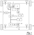
- FIG. 1 presents a hybrid vehicle comprising a thermal engine 2 driving by an automatically controlled clutch 4, an automatic gearbox 6 comprising different speed ratios, connected to the front drive wheels 8 of this vehicle.
- the input shaft of the gearbox 6 receiving the movement of the clutch 4 comprises a front electric traction machine 10 powered by a low voltage traction battery 12. In this way the front electric machine 10 can deliver torque to the drive wheels 8 without going through the clutch 4, using the different speed ratios offered by the transmission 6.
- An on-board charger 14 can be connected by an external socket 16 to an electricity distribution network, to recharge the traction battery 12 when the vehicle is stationary.
- the traction battery 12 has a low voltage, which can be for example 220 or 300V.
- the traction battery 12 also powers a main rear electric traction machine 18 connected successively by a reducer 20 and a dog clutch system 22 forming an engagement device, to a rear differential 24 distributing the movement towards the rear wheels of the vehicle 26.
- the engagement device may comprise a clutch.
- the battery of the on-board network 34 can be charged by a DC/DC direct voltage converter 36, receiving electrical energy from the traction battery 12, or from a front 10 or rear 18 electric machine if the energy level of this traction battery is insufficient.
- the electrical machines 10, 18 work as generators, delivering braking torque to recharge the traction battery 12 and recover energy.
- a powertrain computer connected to a vehicle monitoring supervisor controls the operation of this powertrain to meet the driver's demands while optimizing energy consumption and pollutant gas emissions.
- the computer controls the closing or opening of the dog clutch system 22, to respectively allow traction of the vehicle by the rear electric machine 18, or on the contrary not to drive it when the vehicle is moving.
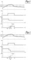
- FIG. 2 presents as a function of time T represented on the horizontal axis, successively from the top, the vehicle speed V, a vehicle speed criterion CV, the position of the control lever LEV of the gearbox 6, and a state of the request to open the engagement device DO.
- the position of the LEV control lever comprises, in succession from the top, a forward position M in which the driver can select the desired gear, an automatic forward position on all gears D, a neutral position N, a reverse position R and a parking position P.
- the vehicle speed V has a high speed threshold Svh which is crossed at time T0 when the vehicle accelerates, and a low speed threshold Svb lower than the high speed threshold, which is crossed at time T1 when the vehicle slows down. Between these two thresholds, a sufficiently high vehicle speed is obtained, allowing the speed criterion CV to move from state 0 to state 1.
- the difference between the high speed threshold Svh and the low speed threshold Svb forms a hysteresis avoiding instability of the speed criterion around a threshold value which would be unique.
- the vehicle is moving in forward gear D with the thermal engine and the electric machine 18 using the dog clutch system 22 which is closed.
- the speed of the vehicle V is slightly increasing, crossing the high speed threshold Svh at time T0.
- the vehicle can be driven in a chosen gear with the M position.
- the method will then apply from this time T2 the same effective time delay Temp since the vehicle speed is identical, leading to time T3 where it checks whether the neutral position request N is still present. This condition not being verified at time T3, the method then does not issue a request for opening DO of the dog clutch system 22 which remains at level 0.
- the electric machine 18 remains attached to the rear wheels 26, the driver can immediately request reverse driving with this electric machine, without waiting time, which improves the performance.
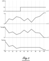
- FIG. 4 presents as a function of time T represented on the horizontal axis, successively starting from the top, the position of the gear lever LEV, the speed of the vehicle V, a raw time delay Temp B depending on the speed, and the effective time delay Temp used by the method to deliver the request to open the dog clutch system 22.
- the gross time delay Temp B varies inversely with respect to the vehicle speed V, decreasing when this speed increases and increasing when this speed decreases.
- the effective time delay Temp is identical to the gross time delay temp B. This variation of the effective time delay Time inverse to the vehicle speed V, allows better anticipation of the confirmation time required before the request to open the dog clutch system 22.
- the effective time delay Temp At time t4 the driver requests the neutral position N, the effective time delay Temp from this moment becomes stabilized. Generally speaking, for this period, a stabilization of the effective time delay Temp can be achieved, or a decrease, but in no case an increase because a change in the control request of the dog clutch system 22 could be obtained, creating instability.
- the request to open the dog clutch system 22 may be conditional on exceeding the minimum speed threshold of the vehicle comprising the high speed threshold Svh and the low speed threshold Svb, with the speed criterion CV at state 1, reached for example during a forward maneuver, when the driver requests reverse gear before stopping this vehicle to anticipate its reversing.
- Temp time delay can also depend on any other parameter that can have an effect on the opening or closing time of the dog clutch system 22, such as the outside temperature, the temperature of the oil in this system, the altitude of the vehicle or the driving gradient.
- the method according to the invention makes it possible to improve the availability of driving with the electric traction machine 18, by reducing the waiting times before its coupling.
Landscapes
- Engineering & Computer Science (AREA)
- Transportation (AREA)
- Mechanical Engineering (AREA)
- Chemical & Material Sciences (AREA)
- Combustion & Propulsion (AREA)
- Automation & Control Theory (AREA)
- Electric Propulsion And Braking For Vehicles (AREA)
- Hybrid Electric Vehicles (AREA)
- Control Of Transmission Device (AREA)
- Control Of Vehicle Engines Or Engines For Specific Uses (AREA)
Description
- La présente invention concerne un procédé de contrôle sur un véhicule hybride d'un dispositif d'engagement d'une machine électrique avec les roues, ainsi qu'un véhicule hybride comportant des moyens mettant en œuvre un tel procédé de contrôle.
- Un type de véhicule hybride utilisant l'énergie électrique, appelé « Full hybride » pour hybride complet en langue anglaise, comporte une première motorisation disposant d'un moteur thermique relié par une boîte de vitesses automatique à des roues du véhicule, et une machine électrique annexe reliée à la boîte de vitesses automatique pour ajouter un couple moteur en prélevant une énergie sur une batterie basse tension, ou pour recharger cette batterie en prélevant un couple moteur.
- Une deuxième motorisation comprenant une machine électrique principale de traction alimentée par la batterie basse tension, est reliée à des roues par un dispositif d'engagement qui peut comporter un embrayage ou des crabots. En particulier le moteur thermique peut entraîner les roues avant du véhicule, et la deuxième motorisation les roues arrière.
- Les deux motorisations permettent de réaliser un roulage avec le moteur thermique seul, un roulage avec le moteur thermique et les machines électriques afin d'augmenter la puissance disponible, un roulage sans émission de gaz polluants avec les machines électriques uniquement, ou une récupération d'énergie lors des freinages en utilisant ces machines en génératrice.
- La machine électrique principale entraînée en rotation en fonctionnant à vide, absorbe par son freinage une puissance sensiblement proportionnelle à sa vitesse de rotation, qui peut dépasser 1kW pour des vitesses supérieures à 80km/h. Afin de réduire les pertes par un entraînement à vide de cette machine électrique, son dispositif d'engagement est si possible ouvert quand cette machine n'est pas utilisée.
- De plus on peut fermer systématiquement le dispositif d'engagement aux basses vitesses, par exemple inférieure à 50km/h, afin d'améliorer la prestation du véhicule en mode électrique en obtenant une meilleure réactivité. On peut aussi ouvrir systématiquement le dispositif d'engagement au-delà d'une certaine vitesse, pour éviter d'endommager la machine électrique présentant une vitesse limite.
- Par ailleurs un type de transmission pour un véhicule hybride, présenté notamment par le document
US-A1-20150045179 , comporte deux machines électriques et un train planétaire permettant de réaliser successivement une position de marche avant « D », une position neutre « N » de point mort, une position de marche arrière « R » et une position de parking « P » bloquant la transmission, qui sont commandées dans cet ordre par un levier actionné par le conducteur. - D'une manière générale les boîtes de vitesses automatiques comportent cette succession de positions, qui permet au conducteur de passer rapidement de la marche avant D vers la marche arrière R et inversement sans s'arrêter sur la position neutre N, afin de réaliser des manoeuvres de parking.
- Pour les véhicules hybrides comportant une machine électrique principale entraînant des roues par le dispositif d'engagement, ce dispositif est fermé suivant la consigne de couple demandé par le conducteur, ce qui nécessite un temps de couplage pouvant varier entre 0,3 et 1,5 seconde selon la technologie du dispositif. Un crabot peut s'engager en plus de 0,8 seconde, un embrayage est plus rapide à fermer.
- Avec un levier de commande disposé dans la position neutre N ou parking P, l'ouverture du dispositif d'engagement est systématique pour des raisons sécuritaires afin de désaccoupler la chaîne de transmission de la machine électrique.
- Dans ce cas lors de manoeuvres de parking, un passage de la marche avant D à la marche arrière R ou inversement passe systématiquement par la position intermédiaire du neutre N qui génère alors automatiquement une ouverture du dispositif d'engagement. Malgré un passage rapide sur la position neutre N, une fois l'ouverture du dispositif d'engagement demandé et commencé cette opération s'accomplit entièrement, avant de procéder juste après à sa fermeture pour le roulage sur la position suivante.
- On obtient un temps d'attente pour obtenir la disponibilité de roulage avec la machine électrique sur la position suivante, qui pose des problèmes de prestations dégradées de conduite.
- On connaît en outre du document
FR-A1-3048397 - La présente invention a notamment pour but d'éviter ces inconvénients de la technique antérieure.
- Elle propose à cet effet un procédé de contrôle selon la revendication 1.
- Un avantage de ce procédé de contrôle est que pour un passage rapide effectué par le conducteur de la position initiale de marche avant vers la position finale de marche arrière, ou inversement, en franchissant avec le levier de commande la position neutre sans s'y arrêter, le temps de passage sur cette position neutre étant inférieur à la temporisation ne permet pas de commander l'ouverture du dispositif d'engagement.
- L'arrivée sur la position finale de marche avant ou arrière trouve le dispositif d'engagement fermé, s'il était déjà fermé sur la position initiale, permettant instantanément un démarrage du véhicule sur cette position finale avec une traction par la machine électrique. Le conducteur obtient une bonne réactivité du véhicule qui est satisfaisante.
- Selon l'invention, avant le passage sur la position neutre, le procédé calcule une temporisation brute présentant une durée qui varie de manière inversée par rapport à la vitesse du véhicule et, au moment du passage sur la position neutre, le procédé calcule la temporisation effective à partir de la temporisation brute de ce moment.
- Avantageusement la temporisation effective présente une durée qui n'augmente pas après le moment de passage de la position neutre.
- En particulier, la temporisation effective peut présenter une durée stabilisée à partir du moment de passage de la position neutre.
- Avantageusement, le procédé impose la temporisation effective pour une vitesse du véhicule dépassant un seuil minimum de vitesse.
- Dans ce cas, avantageusement le seuil minimum de vitesse comporte un seuil de vitesse haut qui est franchi lors d'une accélération du véhicule, et un seuil de vitesse bas inférieur au seuil de vitesse haut, qui est franchi lors d'un ralentissement de ce véhicule.
- Avantageusement, la temporisation brute dépend de paramètres ayant un effet sur le temps d'ouverture ou de fermeture du système d'engagement, comprenant en particulier la température extérieure, la température de l'huile de ce système, l'altitude du véhicule ou la pente du roulage.
- L'invention a de plus pour objet un véhicule automobile selon la revendication 7.
- En particulier, la machine électrique peut être reliée aux roues arrière du véhicule par le dispositif d'engagement comportant des crabots.
- L'invention sera mieux comprise, et d'autres buts, caractéristiques, détails et avantages de celle-ci apparaîtront plus clairement dans la description explicative qui va suivre, faite en référence aux dessins annexés donnés uniquement à titre d'exemple illustrant un mode de réalisation de l'invention, et dans lesquels :
- la
figure 1 est un schéma d'un véhicule hybride mettant en œuvre un procédé de contrôle selon l'invention ; - les
figures 2 et 3 sont des schémas présentant lors du roulage du véhicule, en fonction du temps différents paramètres de fonctionnement pour une ouverture du dispositif d'engagement qui est respectivement activée et inactivée ; et - la
figure 4 est un schéma présentant les variations de la durée de temporisation suivant la vitesse du véhicule. - La
figure 1 présente un véhicule hybride comportant un moteur thermique 2 entraînant par un embrayage 4 piloté de manière automatique, une boîte de vitesses automatique 6 comportant différents rapports de vitesse, reliée aux roues avant motrices 8 de ce véhicule. - L'arbre d'entrée de la boîte de vitesses 6 recevant le mouvement de l'embrayage 4, comporte une machine électrique avant de traction 10 alimentée par une batterie basse tension de traction 12. De cette manière la machine électrique avant 10 peut délivrer un couple sur les roues motrices 8 sans passer par l'embrayage 4, en utilisant les différents rapports de vitesse proposés par la transmission 6.
- Un chargeur embarqué 14 peut être relié par une prise extérieure 16 à un réseau de distribution d'électricité, pour recharger la batterie de traction 12 quand le véhicule est à l'arrêt. La batterie de traction 12 présente une basse tension, qui peut être par exemple de 220 ou 300V.
- La batterie de traction 12 alimente aussi une machine électrique arrière principale de traction 18 reliée successivement par un réducteur 20 et un système de crabotage 22 formant un dispositif d'engagement, à un différentiel arrière 24 répartissant le mouvement vers les roues arrière du véhicule 26. En variante le dispositif d'engagement peut comporter un embrayage.
- Un alternateur 30 relié en permanence par une courroie 32 au moteur thermique 2, alimente un réseau de bord 34 comportant une batterie très basse tension. En complément la batterie du réseau de bord 34 peut être chargée par un convertisseur de tension continue DC/DC 36, recevant une énergie électrique de la batterie de traction 12, ou d'une machine électrique avant 10 ou arrière 18 si le niveau d'énergie de cette batterie de traction est insuffisant.
- Lors des freinages du véhicule ou d'un relâchement de la pédale d'accélérateur, les machines électriques 10, 18 travaillent en génératrice en délivrant un couple de freinage, pour recharger la batterie de traction 12 et récupérer une énergie.
- Un calculateur du groupe motopropulseur relié à un superviseur de surveillance du véhicule, contrôle le fonctionnement de ce groupe motopropulseur pour répondre aux demandes du conducteur tout en optimisant les consommations d'énergie et les émissions de gaz polluants.
- En particulier le calculateur commande la fermeture ou l'ouverture du système de crabotage 22, pour respectivement permettre une traction du véhicule par la machine électrique arrière 18, ou au contraire ne pas l'entraîner lors du roulage du véhicule.
- La
figure 2 présente en fonction du temps T représenté sur l'axe horizontal, successivement en partant du haut, la vitesse du véhicule V, un critère de vitesse du véhicule CV, la position du levier de commande LEV de la boîte de vitesses 6, et un état de la demande d'ouverture du dispositif d'engagement DO. - La position du levier de commande LEV comporte successivement en partant du haut, une position de marche avant M dans laquelle le conducteur peut sélectionner le rapport choisi, une position de marche avant automatique sur tous les rapports D, une position neutre N, une position de marche arrière R et une position de parking P.
- La vitesse du véhicule V comporte un seuil de vitesse haut Svh qui est franchi au temps T0 lors d'une accélération de ce véhicule, et un seuil de vitesse bas Svb inférieur au seuil de vitesse haut, qui est franchi au temps T1 lors d'un ralentissement. On obtient entre ces deux seuils une vitesse suffisamment élevée du véhicule, permettant au critère de vitesse CV de passer de l'état 0 à l'état 1.
- L'écart entre le seuil de vitesse haut Svh et le seuil de vitesse bas Svb forme une hystérésis évitant une instabilité du critère de vitesse autour d'une valeur de seuil qui serait unique.
- Au départ le véhicule roule en marche avant D avec le moteur thermique, et la machine électrique 18 utilisant le système de crabotage 22 qui est fermé. La vitesse du véhicule V est légèrement croissante, en franchissant le seuil de vitesse haut Svh au temps T0.
- En variante le véhicule peut rouler sur un rapport de vitesse choisi avec la position M.
- Au temps T2 un peu après le temps T0, le conducteur déplace le levier de commande de la boîte de vitesses automatique 6 pour passer de la position de marche avant D à la position neutre N, et rester sur cette position neutre.
- Le procédé va alors appliquer à partir de ce temps T2 une temporisation effective Temp dépendant de la vitesse du véhicule, conduisant au temps T3 où il vérifie si la demande de position neutre N est toujours présente. Cette condition étant vérifiée, au temps T3 le procédé émet une demande d'ouverture DO du système de crabotage 22 qui passe au niveau 1, la machine électrique 18 est désolidarisée des roues arrière 26.
- La
figure 3 présente les mêmes conditions de départ que celles présentéesfigure 2 . - Au temps T2 le conducteur déplace le levier de commande de la boîte de vitesses automatique pour passer de la position de marche avant D à la position de marche arrière R atteinte au temps T4, en passant de manière rapide sur la position neutre N.
- Le procédé va alors appliquer à partir de ce temps T2 la même temporisation effective Temp puisque la vitesse du véhicule est identique, conduisant au temps T3 où il vérifie si la demande de position neutre N est toujours présente. Cette condition n'étant pas vérifiée au temps T3, le procédé n'émet alors pas de demande d'ouverture DO du système de crabotage 22 qui reste au niveau 0.
- La machine électrique 18 reste solidarisée des roues arrière 26, le conducteur peut aussitôt demander un roulage en marche arrière avec cette machine électrique, sans temps d'attente ce qui améliore la prestation.
- La
figure 4 présente en fonction du temps T représenté sur l'axe horizontal, successivement en partant du haut, la position du levier de vitesse LEV, la vitesse du véhicule V, une temporisation brute Temp B dépendant de la vitesse, et la temporisation effective Temp utilisée par le procédé pour délivrer la demande d'ouverture du système de crabotage 22. - Du temps t0 au temps t4 le véhicule roule en marche avant D. La temporisation brute Temp B varie de manière inversée par rapport à la vitesse du véhicule V, en diminuant quand cette vitesse s'accroît et en augmentant quand cette vitesse baisse. La temporisation effective Temp est identique à la temporisation brute temp B. Cette variation de la temporisation effective Temps à l'inverse de la vitesse du véhicule V, permet de mieux anticiper le temps de confirmation nécessaire avant la demande d'ouverture du système de crabotage 22.
- Au temps t4 le conducteur demande la position neutre N, la temporisation effective Temp à partir de ce moment devient stabilisée. D'une manière générale on peut réaliser pour cette période une stabilisation de la temporisation effective Temp, ou une diminution, mais en aucun cas une augmentation car on pourrait obtenir un changement de demande de pilotage du système de crabotage 22 créant une instabilité.
- De plus la demande d'ouverture du système de crabotage 22 peut être conditionnée au dépassement du seuil de vitesse minimum du véhicule comprenant le seuil de vitesse haut Svh et le seuil de vitesse bas Svb, avec le critère de vitesse CV à l'état 1, atteint par exemple lors d'une manoeuvre en marche avant, quand le conducteur demande la marche arrière avant l'arrêt de ce véhicule pour anticiper son recul.
- Par ailleurs la temporisation Temp peut aussi dépendre de tout autre paramètre pouvant avoir un effet sur le temps d'ouverture ou de fermeture du système de crabotage 22, comme la température extérieure, la température de l'huile de ce système, l'altitude du véhicule ou la pente du roulage.
- D'une manière générale, le procédé selon l'invention permet d'améliorer la disponibilité du roulage avec la machine électrique de traction 18, en réduisant des temps morts d'attente avant son accouplement.
Claims (8)
- Procédé de contrôle d'un dispositif d'engagement (22) reliant une machine électrique (18) à des roues (26) d'un véhicule hybride, ce véhicule comportant un moteur thermique (2) entraînant des roues (8) par une boîte de vitesses (6) commandée par un levier présentant successivement des positions de marche avant (M, D), une position neutre (N) et une position de marche arrière (R), caractérisé en ce que dans le cas d'un passage d'une position de marche avant (M, D) ou de la position de marche arrière (R), vers la position neutre (N), il impose une temporisation effective (Temp) avant de demander une ouverture du dispositif d'engagement (22), et avant le passage sur la position neutre (N), il calcule une temporisation brute (Temp B) présentant une durée qui varie de manière inversée par rapport à la vitesse du véhicule (V), et au moment du passage sur la position neutre (N) il calcule la temporisation effective (Temp) à partir de la temporisation brute (Temp B) de ce moment.
- Procédé de contrôle selon la revendication 1, dans lequel la temporisation effective (Temp) présente une durée qui n'augmente pas après le moment de passage de la position neutre (N).
- Procédé de contrôle selon la revendication 2, dans lequel la temporisation effective (Temp) présente une durée stabilisée à partir du moment de passage de la position neutre (N).
- Procédé de contrôle selon l'une quelconque des revendications précédentes, imposant la temporisation effective (Temp) pour une vitesse du véhicule (V) dépassant un seuil minimum de vitesse.
- Procédé de contrôle selon la revendication 4, dans lequel le seuil minimum de vitesse comporte un seuil de vitesse haut (Svh) qui est franchi lors d'une accélération du véhicule, et un seuil de vitesse bas (Svb) inférieur au seuil de vitesse haut (Svh), qui est franchi lors d'un ralentissement de ce véhicule.
- Procédé de contrôle selon l'une quelconque des revendications 1 à 5, dans lequel la temporisation brute (Temp B) dépend de paramètres ayant un effet sur le temps d'ouverture ou de fermeture du système d'engagement (22), comprenant en particulier la température extérieure, la température de l'huile de ce système, l'altitude du véhicule ou la pente du roulage.
- Véhicule automobile hybride équipé d'un moteur thermique (2) entraînant des roues (8) par une boîte de vitesses (6) commandée par un levier, et une machine électrique (18) reliée à des roues (26) par un dispositif d'engagement (22), caractérisé en ce qu'il comporte des moyens mettant en œuvre un procédé de contrôle de ce dispositif d'engagement (22) selon l'une quelconque des revendications précédentes.
- Véhicule automobile selon la revendication 7, dans lequel la machine électrique (18) est reliée aux roues arrière (26) du véhicule par le dispositif d'engagement (22) comportant des crabots.
Applications Claiming Priority (2)
| Application Number | Priority Date | Filing Date | Title |
|---|---|---|---|
| FR1760734A FR3073480B1 (fr) | 2017-11-15 | 2017-11-15 | Procede de controle d’un dispositif d’engagement d’une machine electrique de vehicule hybride |
| PCT/FR2018/052513 WO2019097129A1 (fr) | 2017-11-15 | 2018-10-10 | Procede de contrôle d'un dispositif d'engagement d'une machine électrique de vehicule hybride |
Publications (2)
| Publication Number | Publication Date |
|---|---|
| EP3710300A1 EP3710300A1 (fr) | 2020-09-23 |
| EP3710300B1 true EP3710300B1 (fr) | 2025-07-09 |
Family
ID=61027927
Family Applications (1)
| Application Number | Title | Priority Date | Filing Date |
|---|---|---|---|
| EP18800246.3A Active EP3710300B1 (fr) | 2017-11-15 | 2018-10-10 | Procédé de contrôle d'un dispositif d'engagement d'une machine électrique de véhicule hybride, et véhicule automobile hybride |
Country Status (4)
| Country | Link |
|---|---|
| EP (1) | EP3710300B1 (fr) |
| CN (1) | CN111372802B (fr) |
| FR (1) | FR3073480B1 (fr) |
| WO (1) | WO2019097129A1 (fr) |
Families Citing this family (1)
| Publication number | Priority date | Publication date | Assignee | Title |
|---|---|---|---|---|
| GB2594275B (en) * | 2020-04-21 | 2022-10-05 | Jaguar Land Rover Ltd | Apparatus and method for controlling an electric machine |
Family Cites Families (16)
| Publication number | Priority date | Publication date | Assignee | Title |
|---|---|---|---|---|
| DE4213589C2 (de) * | 1991-05-06 | 2001-02-08 | Volkswagen Ag | Verfahren zum Betrieb eines Kraftfahrzeugs |
| FR2779989B1 (fr) * | 1998-06-17 | 2000-08-04 | Valeo | Procede de fabrication d'un materiau de friction et plus particulierement d'une couronne de friction pour disque de friction d'embrayage et couronne d'embrayage |
| JP2002188658A (ja) * | 2000-12-20 | 2002-07-05 | Toyota Motor Corp | 車両用クラッチの係合状態判定装置 |
| JP2004352813A (ja) * | 2003-05-28 | 2004-12-16 | Nisshinbo Ind Inc | 摩擦材 |
| FR2927849B1 (fr) * | 2008-02-26 | 2010-05-07 | Peugeot Citroen Automobiles Sa | Procede de couplage d'une machine electrique de traction sur un vehicule hybride et vehicule hybride pour la mise en oeuvre du procede |
| EP2491089B2 (fr) * | 2009-10-23 | 2023-02-01 | Federal-Mogul Products US LLC | Materiau de frottement pour freins friction |
| GB2488529A (en) * | 2011-02-18 | 2012-09-05 | Land Rover Uk Ltd | Vehicle with power transfer clutch actuator which reduces mode chattering |
| DE112012005972T5 (de) * | 2012-03-02 | 2014-12-04 | Toyota Jidosha Kabushiki Kaisha | Antriebsgerät für ein Hybridfahrzeug |
| JP5799873B2 (ja) * | 2012-03-29 | 2015-10-28 | アイシン・エィ・ダブリュ株式会社 | ハイブリッド車両の制御装置 |
| US9428181B2 (en) * | 2012-08-31 | 2016-08-30 | Nissan Motor Co., Ltd. | Neutral determination device and vehicle control apparatus |
| JP5854156B2 (ja) * | 2012-12-26 | 2016-02-09 | 日産自動車株式会社 | 電動車両の変速制御装置 |
| FR3005709B1 (fr) * | 2013-05-17 | 2015-05-29 | Peugeot Citroen Automobiles Sa | Procede de commande d’un groupe moto propulseur a moteur thermique et a boite de vitesses automatisee |
| US9731706B2 (en) * | 2015-03-24 | 2017-08-15 | Ford Global Technologies, Llc | Coordinating non-demand engine start and stop with gear shift |
| US9604635B1 (en) * | 2015-09-21 | 2017-03-28 | Ford Global Technologies, Llc | Inhibit engine pull-down based on past driving history |
| CN106838290B (zh) * | 2015-12-03 | 2019-09-10 | 上海汽车集团股份有限公司 | 车辆空档油门控制方法及装置 |
| FR3048397B1 (fr) * | 2016-03-02 | 2020-09-11 | Peugeot Citroen Automobiles Sa | Controle du fonctionnement d'un moteur thermique d'un vehicule hybride paralelle a boite de vitesses manuelle |
-
2017
- 2017-11-15 FR FR1760734A patent/FR3073480B1/fr active Active
-
2018
- 2018-10-10 CN CN201880074420.0A patent/CN111372802B/zh active Active
- 2018-10-10 WO PCT/FR2018/052513 patent/WO2019097129A1/fr not_active Ceased
- 2018-10-10 EP EP18800246.3A patent/EP3710300B1/fr active Active
Also Published As
| Publication number | Publication date |
|---|---|
| WO2019097129A1 (fr) | 2019-05-23 |
| EP3710300A1 (fr) | 2020-09-23 |
| FR3073480B1 (fr) | 2020-11-13 |
| FR3073480A1 (fr) | 2019-05-17 |
| CN111372802A (zh) | 2020-07-03 |
| CN111372802B (zh) | 2023-06-02 |
Similar Documents
| Publication | Publication Date | Title |
|---|---|---|
| EP1128977B1 (fr) | Procede de commande du couple moteur pendant les changements de vitesse | |
| FR2958613A1 (fr) | Procede de gestion d'un vehicule et dispositif pour sa mise en oeuvre | |
| FR2822758A1 (fr) | Chaine motrice | |
| FR2999138A1 (fr) | Procede de controle de couples lors du demarrage du moteur thermique d'un vehicule hybride, pour passer d'un mode electrique a un mode hybride | |
| EP3710300B1 (fr) | Procédé de contrôle d'un dispositif d'engagement d'une machine électrique de véhicule hybride, et véhicule automobile hybride | |
| EP4486588B1 (fr) | Procédé de limitation de glissement en fonction d'un rapport de vitesse lors d'une phase de démarrage d'un moteur thermique d'une chaîne de traction hybride | |
| EP2861892B1 (fr) | Procédé et dispositif de contrôle de la vitesse engagée d'une boîte de vitesses automatisée de véhicule, en fonction d'une accélération demandée par un système de contrôle de vitesse | |
| EP2928715B1 (fr) | Procede de controle de couples lors du changement de rapport d'une boite de vitesses d'un vehicule hybride | |
| EP3074257B1 (fr) | Procede et systeme de demarrage d'un moteur thermique | |
| EP2516235B1 (fr) | Procede et dispositif pour obtenir un decollage a forte charge de vehicules hybrides | |
| EP3072230B1 (fr) | Procede de commande d'un alternateur associe a un moteur thermique de vehicule automobile | |
| EP2996916B1 (fr) | Procédé de commande d'un groupe moto propulseur a moteur thermique et a boite de vitesses automatisée | |
| FR3062358A1 (fr) | Groupe moto-propulseur de vehicule automobile hybride | |
| FR2923792A1 (fr) | Procede de pilotage du passage d'un mode electrique a un mode mixte electrique et thermique d'un groupe motopropulseur hybride et groupe motopropulseur hybride | |
| EP4153439B1 (fr) | Procédé de commande d'un groupe motopropulseur pour véhicule automobile à transmission électrique hybride | |
| FR2928600A1 (fr) | Groupe motopropulseur et procede de controle d'un groupe motopropulseur pendant un demarrage lance | |
| FR3070946A1 (fr) | Procede de commande de la gestion du groupe moto-propulseur d’un vehicule automobile | |
| EP2512897A1 (fr) | Procede et dispositif pour compenser une valeur perdue de couple de traction de vehicule | |
| FR3145954A1 (fr) | Procédé de pilotage d’un embrayage de véhicule automobile | |
| EP1174302B1 (fr) | Procédé de commande pour un groupe motopropulseur | |
| FR3105115A1 (fr) | Procede de commande d'une chaîne de traction d’un vehicule | |
| EP2920038B1 (fr) | Procédé et dispositif de contrôle des couples de moteurs thermique et auxiliaire(s) d'un véhicule hybride, en présence d'un incrément de consigne | |
| FR2993937A1 (fr) | Procede de determination du moyen de demarrage utilise pour demarrer un moteur thermique d'un vehicule automobile hybride | |
| FR3145726A1 (fr) | Procédé de commande d’une chaîne de propulsion d’un véhicule hybride | |
| WO2021099699A1 (fr) | Procede de pilotage d'une machine motrice anticipant un regime de consigne lors d'une phase de synchronisation |
Legal Events
| Date | Code | Title | Description |
|---|---|---|---|
| STAA | Information on the status of an ep patent application or granted ep patent |
Free format text: STATUS: UNKNOWN |
|
| STAA | Information on the status of an ep patent application or granted ep patent |
Free format text: STATUS: THE INTERNATIONAL PUBLICATION HAS BEEN MADE |
|
| PUAI | Public reference made under article 153(3) epc to a published international application that has entered the european phase |
Free format text: ORIGINAL CODE: 0009012 |
|
| STAA | Information on the status of an ep patent application or granted ep patent |
Free format text: STATUS: REQUEST FOR EXAMINATION WAS MADE |
|
| 17P | Request for examination filed |
Effective date: 20200602 |
|
| AK | Designated contracting states |
Kind code of ref document: A1 Designated state(s): AL AT BE BG CH CY CZ DE DK EE ES FI FR GB GR HR HU IE IS IT LI LT LU LV MC MK MT NL NO PL PT RO RS SE SI SK SM TR |
|
| AX | Request for extension of the european patent |
Extension state: BA ME |
|
| RAP1 | Party data changed (applicant data changed or rights of an application transferred) |
Owner name: PSA AUTOMOBILES SA |
|
| DAV | Request for validation of the european patent (deleted) | ||
| DAX | Request for extension of the european patent (deleted) | ||
| STAA | Information on the status of an ep patent application or granted ep patent |
Free format text: STATUS: EXAMINATION IS IN PROGRESS |
|
| 17Q | First examination report despatched |
Effective date: 20230719 |
|
| RAP3 | Party data changed (applicant data changed or rights of an application transferred) |
Owner name: STELLANTIS AUTO SAS |
|
| GRAP | Despatch of communication of intention to grant a patent |
Free format text: ORIGINAL CODE: EPIDOSNIGR1 |
|
| STAA | Information on the status of an ep patent application or granted ep patent |
Free format text: STATUS: GRANT OF PATENT IS INTENDED |
|
| INTG | Intention to grant announced |
Effective date: 20250305 |
|
| GRAS | Grant fee paid |
Free format text: ORIGINAL CODE: EPIDOSNIGR3 |
|
| GRAA | (expected) grant |
Free format text: ORIGINAL CODE: 0009210 |
|
| STAA | Information on the status of an ep patent application or granted ep patent |
Free format text: STATUS: THE PATENT HAS BEEN GRANTED |
|
| AK | Designated contracting states |
Kind code of ref document: B1 Designated state(s): AL AT BE BG CH CY CZ DE DK EE ES FI FR GB GR HR HU IE IS IT LI LT LU LV MC MK MT NL NO PL PT RO RS SE SI SK SM TR |
|
| REG | Reference to a national code |
Ref country code: GB Ref legal event code: FG4D Free format text: NOT ENGLISH |
|
| REG | Reference to a national code |
Ref country code: CH Ref legal event code: EP |
|
| REG | Reference to a national code |
Ref country code: DE Ref legal event code: R084 Ref document number: 602018083445 Country of ref document: DE |
|
| REG | Reference to a national code |
Ref country code: IE Ref legal event code: FG4D Free format text: LANGUAGE OF EP DOCUMENT: FRENCH |
|
| REG | Reference to a national code |
Ref country code: DE Ref legal event code: R096 Ref document number: 602018083445 Country of ref document: DE |
|
| PGFP | Annual fee paid to national office [announced via postgrant information from national office to epo] |
Ref country code: FR Payment date: 20250924 Year of fee payment: 8 |
|
| REG | Reference to a national code |
Ref country code: NL Ref legal event code: MP Effective date: 20250709 |
|
| PG25 | Lapsed in a contracting state [announced via postgrant information from national office to epo] |
Ref country code: PT Free format text: LAPSE BECAUSE OF FAILURE TO SUBMIT A TRANSLATION OF THE DESCRIPTION OR TO PAY THE FEE WITHIN THE PRESCRIBED TIME-LIMIT Effective date: 20251110 |
|
| PG25 | Lapsed in a contracting state [announced via postgrant information from national office to epo] |
Ref country code: NL Free format text: LAPSE BECAUSE OF FAILURE TO SUBMIT A TRANSLATION OF THE DESCRIPTION OR TO PAY THE FEE WITHIN THE PRESCRIBED TIME-LIMIT Effective date: 20250709 |
|
| REG | Reference to a national code |
Ref country code: AT Ref legal event code: MK05 Ref document number: 1811564 Country of ref document: AT Kind code of ref document: T Effective date: 20250709 |
|
| PG25 | Lapsed in a contracting state [announced via postgrant information from national office to epo] |
Ref country code: IS Free format text: LAPSE BECAUSE OF FAILURE TO SUBMIT A TRANSLATION OF THE DESCRIPTION OR TO PAY THE FEE WITHIN THE PRESCRIBED TIME-LIMIT Effective date: 20251109 |
|
| PGFP | Annual fee paid to national office [announced via postgrant information from national office to epo] |
Ref country code: DE Payment date: 20250923 Year of fee payment: 8 |
|
| PG25 | Lapsed in a contracting state [announced via postgrant information from national office to epo] |
Ref country code: NO Free format text: LAPSE BECAUSE OF FAILURE TO SUBMIT A TRANSLATION OF THE DESCRIPTION OR TO PAY THE FEE WITHIN THE PRESCRIBED TIME-LIMIT Effective date: 20251009 |
|
| REG | Reference to a national code |
Ref country code: LT Ref legal event code: MG9D |
|
| PG25 | Lapsed in a contracting state [announced via postgrant information from national office to epo] |
Ref country code: AT Free format text: LAPSE BECAUSE OF FAILURE TO SUBMIT A TRANSLATION OF THE DESCRIPTION OR TO PAY THE FEE WITHIN THE PRESCRIBED TIME-LIMIT Effective date: 20250709 |
|
| PG25 | Lapsed in a contracting state [announced via postgrant information from national office to epo] |
Ref country code: FI Free format text: LAPSE BECAUSE OF FAILURE TO SUBMIT A TRANSLATION OF THE DESCRIPTION OR TO PAY THE FEE WITHIN THE PRESCRIBED TIME-LIMIT Effective date: 20250709 |
|
| PG25 | Lapsed in a contracting state [announced via postgrant information from national office to epo] |
Ref country code: HR Free format text: LAPSE BECAUSE OF FAILURE TO SUBMIT A TRANSLATION OF THE DESCRIPTION OR TO PAY THE FEE WITHIN THE PRESCRIBED TIME-LIMIT Effective date: 20250709 |
|
| PG25 | Lapsed in a contracting state [announced via postgrant information from national office to epo] |
Ref country code: GR Free format text: LAPSE BECAUSE OF FAILURE TO SUBMIT A TRANSLATION OF THE DESCRIPTION OR TO PAY THE FEE WITHIN THE PRESCRIBED TIME-LIMIT Effective date: 20251010 |
|
| PG25 | Lapsed in a contracting state [announced via postgrant information from national office to epo] |
Ref country code: SE Free format text: LAPSE BECAUSE OF FAILURE TO SUBMIT A TRANSLATION OF THE DESCRIPTION OR TO PAY THE FEE WITHIN THE PRESCRIBED TIME-LIMIT Effective date: 20250709 |
|
| PG25 | Lapsed in a contracting state [announced via postgrant information from national office to epo] |
Ref country code: LV Free format text: LAPSE BECAUSE OF FAILURE TO SUBMIT A TRANSLATION OF THE DESCRIPTION OR TO PAY THE FEE WITHIN THE PRESCRIBED TIME-LIMIT Effective date: 20250709 |
|
| PG25 | Lapsed in a contracting state [announced via postgrant information from national office to epo] |
Ref country code: PL Free format text: LAPSE BECAUSE OF FAILURE TO SUBMIT A TRANSLATION OF THE DESCRIPTION OR TO PAY THE FEE WITHIN THE PRESCRIBED TIME-LIMIT Effective date: 20250709 Ref country code: BG Free format text: LAPSE BECAUSE OF FAILURE TO SUBMIT A TRANSLATION OF THE DESCRIPTION OR TO PAY THE FEE WITHIN THE PRESCRIBED TIME-LIMIT Effective date: 20250709 |
|
| PG25 | Lapsed in a contracting state [announced via postgrant information from national office to epo] |
Ref country code: RS Free format text: LAPSE BECAUSE OF FAILURE TO SUBMIT A TRANSLATION OF THE DESCRIPTION OR TO PAY THE FEE WITHIN THE PRESCRIBED TIME-LIMIT Effective date: 20251009 |
|
| PG25 | Lapsed in a contracting state [announced via postgrant information from national office to epo] |
Ref country code: ES Free format text: LAPSE BECAUSE OF FAILURE TO SUBMIT A TRANSLATION OF THE DESCRIPTION OR TO PAY THE FEE WITHIN THE PRESCRIBED TIME-LIMIT Effective date: 20250709 |
|
| PG25 | Lapsed in a contracting state [announced via postgrant information from national office to epo] |
Ref country code: RO Free format text: LAPSE BECAUSE OF FAILURE TO SUBMIT A TRANSLATION OF THE DESCRIPTION OR TO PAY THE FEE WITHIN THE PRESCRIBED TIME-LIMIT Effective date: 20250709 |
|
| PG25 | Lapsed in a contracting state [announced via postgrant information from national office to epo] |
Ref country code: SM Free format text: LAPSE BECAUSE OF FAILURE TO SUBMIT A TRANSLATION OF THE DESCRIPTION OR TO PAY THE FEE WITHIN THE PRESCRIBED TIME-LIMIT Effective date: 20250709 |
|
| PG25 | Lapsed in a contracting state [announced via postgrant information from national office to epo] |
Ref country code: DK Free format text: LAPSE BECAUSE OF FAILURE TO SUBMIT A TRANSLATION OF THE DESCRIPTION OR TO PAY THE FEE WITHIN THE PRESCRIBED TIME-LIMIT Effective date: 20250709 |
|
| PG25 | Lapsed in a contracting state [announced via postgrant information from national office to epo] |
Ref country code: IT Free format text: LAPSE BECAUSE OF FAILURE TO SUBMIT A TRANSLATION OF THE DESCRIPTION OR TO PAY THE FEE WITHIN THE PRESCRIBED TIME-LIMIT Effective date: 20250709 |
|
| PG25 | Lapsed in a contracting state [announced via postgrant information from national office to epo] |
Ref country code: CZ Free format text: LAPSE BECAUSE OF FAILURE TO SUBMIT A TRANSLATION OF THE DESCRIPTION OR TO PAY THE FEE WITHIN THE PRESCRIBED TIME-LIMIT Effective date: 20250709 |
|
| PG25 | Lapsed in a contracting state [announced via postgrant information from national office to epo] |
Ref country code: EE Free format text: LAPSE BECAUSE OF FAILURE TO SUBMIT A TRANSLATION OF THE DESCRIPTION OR TO PAY THE FEE WITHIN THE PRESCRIBED TIME-LIMIT Effective date: 20250709 Ref country code: SK Free format text: LAPSE BECAUSE OF FAILURE TO SUBMIT A TRANSLATION OF THE DESCRIPTION OR TO PAY THE FEE WITHIN THE PRESCRIBED TIME-LIMIT Effective date: 20250709 |