EP3710287B1 - Spike - Google Patents
Spike Download PDFInfo
- Publication number
- EP3710287B1 EP3710287B1 EP18759042.7A EP18759042A EP3710287B1 EP 3710287 B1 EP3710287 B1 EP 3710287B1 EP 18759042 A EP18759042 A EP 18759042A EP 3710287 B1 EP3710287 B1 EP 3710287B1
- Authority
- EP
- European Patent Office
- Prior art keywords
- tyre
- spike
- tyre stud
- stud
- rubber material
- Prior art date
- Legal status (The legal status is an assumption and is not a legal conclusion. Google has not performed a legal analysis and makes no representation as to the accuracy of the status listed.)
- Active
Links
Images
Classifications
-
- B—PERFORMING OPERATIONS; TRANSPORTING
- B60—VEHICLES IN GENERAL
- B60C—VEHICLE TYRES; TYRE INFLATION; TYRE CHANGING; CONNECTING VALVES TO INFLATABLE ELASTIC BODIES IN GENERAL; DEVICES OR ARRANGEMENTS RELATED TO TYRES
- B60C11/00—Tyre tread bands; Tread patterns; Anti-skid inserts
- B60C11/14—Anti-skid inserts, e.g. vulcanised into the tread band
- B60C11/16—Anti-skid inserts, e.g. vulcanised into the tread band of plug form, e.g. made from metal, textile
- B60C11/1675—Anti-skid inserts, e.g. vulcanised into the tread band of plug form, e.g. made from metal, textile with special shape of the plug- tip
-
- B—PERFORMING OPERATIONS; TRANSPORTING
- B60—VEHICLES IN GENERAL
- B60C—VEHICLE TYRES; TYRE INFLATION; TYRE CHANGING; CONNECTING VALVES TO INFLATABLE ELASTIC BODIES IN GENERAL; DEVICES OR ARRANGEMENTS RELATED TO TYRES
- B60C11/00—Tyre tread bands; Tread patterns; Anti-skid inserts
- B60C11/14—Anti-skid inserts, e.g. vulcanised into the tread band
- B60C11/16—Anti-skid inserts, e.g. vulcanised into the tread band of plug form, e.g. made from metal, textile
-
- B—PERFORMING OPERATIONS; TRANSPORTING
- B60—VEHICLES IN GENERAL
- B60C—VEHICLE TYRES; TYRE INFLATION; TYRE CHANGING; CONNECTING VALVES TO INFLATABLE ELASTIC BODIES IN GENERAL; DEVICES OR ARRANGEMENTS RELATED TO TYRES
- B60C11/00—Tyre tread bands; Tread patterns; Anti-skid inserts
- B60C11/14—Anti-skid inserts, e.g. vulcanised into the tread band
- B60C11/16—Anti-skid inserts, e.g. vulcanised into the tread band of plug form, e.g. made from metal, textile
- B60C11/1643—Anti-skid inserts, e.g. vulcanised into the tread band of plug form, e.g. made from metal, textile with special shape of the plug-body portion, i.e. not cylindrical
-
- B—PERFORMING OPERATIONS; TRANSPORTING
- B60—VEHICLES IN GENERAL
- B60C—VEHICLE TYRES; TYRE INFLATION; TYRE CHANGING; CONNECTING VALVES TO INFLATABLE ELASTIC BODIES IN GENERAL; DEVICES OR ARRANGEMENTS RELATED TO TYRES
- B60C11/00—Tyre tread bands; Tread patterns; Anti-skid inserts
- B60C11/14—Anti-skid inserts, e.g. vulcanised into the tread band
- B60C11/16—Anti-skid inserts, e.g. vulcanised into the tread band of plug form, e.g. made from metal, textile
- B60C11/1693—Attachment of the plug-tip within the plug-body
Definitions
- the invention relates to a spike for anchoring in a spike hole of a tread of a pneumatic vehicle tire with a spike body having a foot flange and with a spike pin made of hard metal, which is anchored in an insert located in the spike body and projects beyond the spike body with an end section, the foot flange having lateral boundary surfaces and the insert has a foot part which forms the foot flange and a pin holder which accommodates the spike pin, and wherein the spike body, possibly apart from the insert, consists of non-metallic material which encases the foot part on the foot flange.
- Spikes are usually held in the spike holes of the tread of pneumatic vehicle tires by a combination of positive fit and clamping.
- Conventional spikes consist of a spike body made of aluminum or steel, in which the spike pin, which protrudes above the tread surface and is made of hard metal, is held.
- a plastic spike which consists of a hard metal pin and a plastic coating, with the hard metal pin being embedded in the plastic shaft using ultrasonic vibrations.
- the hard metal pin is encapsulated with a thermoplastic.
- spike bodies made of rubber are superior to those made of aluminum or steel in terms of abrasion behavior, as they have completely different wear behavior. If the tire rolls over stones on the road surface and especially grit from grit near a conventional spike, the profile in the tread deforms significantly and moves to the side. The fixed, rigid spike cannot follow these evasive movements. This creates a gap between the spike and the rubber, which exposes the surface and outer surface of the spike body to abrasive attack from stones. Since pavement stones and chippings typically have a higher hardness than aluminum and even steel, a spike body made of aluminum or steel is subjected to significant abrading, which reduces the spike body height and diameter of the spike body.
- the DE 10 2009 026112 A1 deals with a conventionally designed spike, which is glued into the spike hole, whereby a capsule containing liquid adhesive is first introduced into the spike hole, so that when the spike is inserted, the spike foot opens the capsule, the liquid adhesive emerges and sticks the spike in the spike hole.
- the liquid adhesive can also be a two-component adhesive, whereby the second component can also be in a capsule or the spike can be coated with the second component before being inserted into the spike hole.
- the adhesive hardens to produce the adhesive bond; the hardened adhesive forms a thin, hard layer between a portion of the spike body and the surrounding rubber material of the tread.
- the invention is based on the object of designing a spike of the type mentioned in such a way that road wear and the formation of fine dust can be reduced even further, while ensuring the grip properties of the spike on icy surfaces, the ice performance, and an optimal hold of the spike in the tread should.
- the part that is primarily responsible for anchoring the spike in the rubber material of the tread namely the foot flange, has a casing made of a vibration-damping rubber material.
- Spikes according to the invention are therefore embedded in the rubber material of the tread in such a way that they absorb forces acting on them from the outside particularly well can dampen.
- the spike body is also preferably and advantageously made of an abrasion-resistant and cut-resistant material in the area that directly adjoins the tread periphery when the spike is inserted in a tread, preferably of a corresponding rubber material or a thermoplastic vulcanizate.
- the abrasion of the spike body therefore essentially adapts well to that of the surrounding rubber matrix of the tread. This means that no gaps form between the spike body and the tread material, meaning that the spike retains its winter properties and ice performance over the life of the tire.
- Spikes designed according to the invention also have a low weight, which is advantageous for low road wear and low fine dust formation.
- the spike body consists of the vibration-damping first rubber material that at least partially encases the foot flange and of the abrasion- and cut-resistant material.
- vibration-damping first rubber material covers the base flange and the pin holder of the insert, at least partially. It is particularly advantageous for the foot flange to have a casing made of a vibration-damping material.
- the spike body has at least one further spike body part made of a further rubber material between the casing of the foot flange made of the vibration-damping first rubber material and the spike body part made of the abrasion and cut-resistant material. This measure makes it possible to provide spikes with special bedding and damping properties.
- the respective separation plane between the different materials can run transversely to the vertical axis of the spike. In an alternative embodiment, it can run obliquely to the vertical axis of the spike, preferably inclined to it at an acute angle of 60 ° to 85 °. This measure allows bedding and The damping properties of the spike body can be particularly well adapted to the respective position of the spike in the tread.
- the invention further relates to a pneumatic vehicle tire with a tread with spikes, which are designed according to the invention.
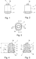
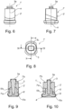
- the spikes shown in the figures 1 ( Fig. 1 to Fig. 5 ) and 1' ( Fig. 6 to Fig. 10 ) have a central vertical axis a and basically consist of a spike body 2, 2 'and an insert 5, 5' with a spike pin 3.
- the spike body 2 has a circular cylindrical or approximately circular cylindrical part, which sits centrally on a foot flange 4, which in plan view has an approximately oval shape with two side surfaces running parallel to one another in the longer extent of the oval.
- the circular cylindrical part has a diameter which, in the embodiment shown, corresponds to the width of the foot flange 4, although the diameter can also be slightly smaller or larger than the width of the foot flange 4 Figures 6 to 10
- the spike body 2 ' has a part which has an oval shape in plan view, the oval remaining constant or largely constant over the height extent of the spike body 2.
- the oval-shaped part is arranged approximately in the middle of a foot flange 4 ', which in plan view has an approximately oval shape with two side surfaces running along the longer extent of the oval, which form a single plane of symmetry S 1 running in the longitudinal extent of the foot flange 4 ' of the foot flange 4' slanted in opposite directions and under a small one acute angles.
- the extent of the oval part of the spike body 2' corresponds to that of the oval of the foot flange 4'.
- the insert 5, 5' is located within the spike body 2, 2', which has a foot part 5a, 5'a which also forms the foot flange 4, 4' and has a substantially analogous design and a pin holder 5b, 5'b .
- the pin holder 5b, 5'b is cylindrical or approximately cylindrical, and the spike pin 3 is anchored in its center.
- the height h of the insert 5, 5' is preferably 40% to 60% of the spike height H.
- the spike pin 3 projects beyond the spike body 2, 2' with an end section 3a in a known manner.
- the insert 5, 5' preferably consists of a metal, in particular aluminum, but can also consist of a plastic, either a thermoset or a thermoplastic.
- the spike body 2, 2' consists of different non-metallic materials, as explained below.
- the foot flange 4 is covered by a first rubber material
- the casing 6 also covers the top of the foot flange 4.
- the pin holder 5b and the section of the spike pin 3 running within the spike body 2 are embedded in a second material, which forms a spike body part 7 .
- the end section 3a of the spike pin 3 that projects beyond the spike body 2 can also be covered with a thin layer of this material.
- the rubber material of the casing 6 of the foot flange 4 has particularly good vibration-damping properties. Compositions of rubber mixtures that are suitable for producing such a rubber material are well known to the tire expert.
- the parting plane between the casing 6 and the spike body part 7 runs horizontally, therefore at right angles to the vertical axis a of the spike 1.
- the casing 6 has a large part in the area of the foot flange 4 Layer thickness of 0.5 to 1.5 mm. However, the layer thickness can also be higher in places, for example in the area of an indentation formed on the underside of the foot part 5a of the insert 5, which is filled with the rubber material of the casing 6.
- the casing made of the first rubber material on the foot flange 4 only extends into the area of its lateral boundary surfaces; the second material is immediately adjacent here.
- the spike body part 7 consists of a cut-resistant and abrasion-resistant material, either of another rubber material or of a thermoplastic vulcanizate.
- Compositions of rubber mixtures for producing a cut-resistant and abrasion-resistant rubber material are well known to the tire expert.
- a thermoplastic vulcanizate consists of at least one thermoplastic and an elastomer, the thermoplastic forming a continuous phase and the elastomer forming a finely distributed disperse phase therein. In a thermoplastic vulcanizate, elastomer particles are surrounded by thermoplastic.
- the thermoplastic is or contains in particular at least one thermoplastic from the group polyurethane (PU), polypropylene (PP), polystyrene (PS), polyamide (PA) or acrylonitrile-butadiene-styrene copolymer (ABS).
- the rubber mixture of the elastomer contains as rubber at least one of the rubbers from the group of natural rubbers (NR), synthetic polyisoprene (IR), polybutadiene (BR), styrene-butadiene rubber (SBR) and nitrile-butadiene rubber (NBR).
- the foot part 5'a is also covered by a first rubber material, which, analogous to the first embodiment, is particularly good at dampening vibrations.
- the casing 6' extends into the lower region of the pin holder 5'b and here forms a dividing plane that runs obliquely, at an acute angle of, for example, 5° to 30° to the horizontal, to a strip-shaped spike body part 7'a from another Rubber material, the part 7'a running around the pin holder 5'b and the part 7'a being followed by a spike body part 7'b made of a cut-resistant and abrasion-resistant material, either made of a rubber material or made of a thermoplastic vulcanizate.
- the spike body part 7'b envelops the upper section of the pin holder 5'b and the section of the spike pin 3 running within the spike body 2' and, if necessary, the end section 3a of the spike pin 3, the latter in a thin layer.
- the parting plane between the two spike body parts 7'a and 7'b preferably runs obliquely analogous to the parting plane between the casing 6' and the spike body part 7'a.
- the separating planes between the casing 6 'and the spike body part 7'a and between the spike body parts 7'a and 7'b run horizontally, therefore at right angles to the central vertical axis a of the spike 1 '.
- the spike body part 7'a preferably consists of a rubber material, which ensures a particularly good connection between the two materials of the casing 6' and the spike body part 7'b.
- the casing 6, 6 ' can reach higher in the vertical direction than shown, in particular also at least partially envelop the pin holder 5b, 5'b, and preferably in the case in the Figures 1 to 5 also completely enclose the version shown.
Landscapes
- Engineering & Computer Science (AREA)
- Mechanical Engineering (AREA)
- Tires In General (AREA)
Description
- Die Erfindung betrifft einen Spike zum Verankern in einem Spikeloch eines Laufstreifens eines Fahrzeugluftreifens mit einem einen Fußflansch aufweisenden Spikekörper und mit einem Spikepin aus Hartmetall, welcher in einem im Spikekörper befindlichen Einsatz verankert ist und mit einem Endabschnitt den Spikekörper überragt, wobei der Fußflansch seitliche Begrenzungsflächen und der Einsatz einen den Fußflansch mitbildenden Fußteil und einen den Spikepin aufnehmenden Pinhalter aufweist, und wobei der Spikekörper, ggf. abgesehen vom Einsatz, aus nicht-metallischem Material besteht, welches am Fußflansch den Fußteil ummantelt.
- Spikes werden üblicherweise durch eine Kombination aus Formschluss und Klemmung in den Spikelöchern des Laufstreifens von Fahrzeugluftreifen gehalten. Herkömmliche Spikes bestehen aus einem Spikekörper aus Aluminium oder Stahl, in welchem der über die Laufstreifenoberfläche hervorstehende Spikepin, der aus Hartmetall besteht, gehalten ist.
- Es ist üblich, auf winterlichen Fahrbahnen zur Erhöhung der Verkehrssicherheit Streugut zu verwenden. Der Einsatz von Sand wurde in den letzten Jahren zugunsten von Streusplit reduziert, da Sand dazu neigt, von Reifen zu Staub oder zu Feinstaub zermahlen zu werden, welcher zum Schutz der Gesundheit der Bevölkerung reduziert oder vermieden werden soll. Der Einsatz von Streusplit führt jedoch dazu, dass die üblichen, in Fahrzeugluftreifen eingesetzten Spikes verstärkt abgenützt werden, insbesondere wenn der Spikekörper aus Aluminium besteht.
- Es ist daher bereits vorgeschlagen worden, Spikes mit Spikekörpern aus Gummi oder aus Kunststoff zu verwenden. Aus der
DE 2 202 373 A1 ist ein Kunststoff-Spike bekannt, welcher aus einem Hartmetallstift und einer Kunststoffummantelung besteht, wobei der Hartmetallstift mittels Ultraschallschwingungen in den Kunststoffschaft eingebettet wird. Bei weiteren bekannten Herstellungsmethoden von Kunststoffspikes wird der Hartmetallpin mit einem thermoplastischen Kunststoff umspritzt. - Aus der
WO 2017/0888995 A1 - Die
DE 10 2009 026112 A1 befasst sich mit einem herkömmlich ausgeführten Spike, welcher im Spikeloch eingeklebt wird, wobei in das Spikeloch zuerst eine Kapsel, die Flüssigklebstoff enthält, eingebracht wird, sodass der Spikefuß beim Einsetzen des Spikes die Kapsel öffnet, der Flüssigklebstoff austritt und den Spike im Spikeloch festklebt. Der Flüssigklebstoff kann auch ein Zwei-Komponenten-Kleber sein, wobei sich die zweite Komponente ebenfalls in einer Kapsel befinden kann oder der Spike vor dem Einführen in das Spikeloch mit der zweiten Komponente beschichtet wird. Bei jeder dieser Ausführungen härtet der Kleber unter Herstellung der Klebeverbindung aus, der ausgehärtete Klebstoff bildet eine dünne, harte Schicht zwischen einem Teilbereich des Spikekörpers und dem umgebenden Gummimaterial des Laufstreifens. - Der Erfindung liegt die Aufgabe zugrunde, einen Spike der eingangs genannten Art derart auszuführen, dass der Straßenverschleiß und die Feinstaubbildung noch weiter reduziert werden können, wobei die Griffeigenschaften des Spikes auf eisigem Untergrund, die Eisperformance, sowie ein optimaler Halt des Spikes im Laufstreifen gewährleistet sein sollen.
- Die gestellte Aufgabe wird erfindungsgemäß durch einen Spike nach Anspruch 1 gelöst.
- Bei erfindungsgemäß ausgeführten Spikes weist daher jener Teil, der für die Verankerung des Spikes im Gummimaterial des Laufstreifens hauptsächlich verantwortlich ist, nämlich der Fußflansch, eine Ummantelung aus einem schwingungsdämpfenden Gummimaterial auf. Erfindungsgemäße Spikes sind daher derart im Gummimaterial des Laufstreifens eingebettet, dass sie von außen auf sie wirkende Kräfte besonders gut aufnehmen und dämpfen können. Der Spikekörper ist ferner in jenem Bereich, der bei in einem Laufstreifen eingesetzten Spike unmittelbar an die Laufstreifenperipherie anschließt, vorzugs- und vorteilhafterweise aus einem abriebbeständigen und schnittfesten Material gefertigt, vorzugsweise aus einem entsprechenden Gummimaterial oder einem thermoplastischen Vulkanisat. Es passt sich daher der Abrieb des Spikekörpers im Wesentlichen an jenen der umgebenden Gummimatrix des Laufstreifens gut an. Dadurch bilden sich keine Spalten zwischen dem Spikekörper und dem Laufstreifenmaterial, wodurch der Spike über die Lebensdauer des Reifens seine Wintereigenschaften bzw. seine Eisperformance behält. Erfindungsgemäß ausgeführte Spikes weisen zudem ein für einen geringen Straßenverschleiß und eine geringe Feinstaubbildung vorteilhaftes geringes Gewicht auf.
- Bei einer bevorzugten Ausführung besteht der Spikekörper aus dem den Fußflansch zumindest zum Teil ummantelnden schwingungsdämpfenden ersten Gummimaterial und aus dem abrieb- und schnittbeständigen Material.
- Besonders bevorzugt ist eine Ausführung, bei der das schwingungsdämpfende erste Gummimaterial den Fußflansch und den Pinhalter des Einsatzes, letzteren zumindest zum Teil, ummantelt. Vor allem für den Fußflansch ist es vorteilhaft, eine Ummantelung aus einem schwingungsdämpfenden Material aufzuweisen.
- Besonders bevorzugt ist des Weiteren eine Ausführungsvariante, bei der der Spikekörper zwischen der Ummantelung des Fußflansches aus dem schwingungsdämpfenden ersten Gummimaterial und dem Spikekörper-Teil aus dem abrieb- und schnittbeständigen Material zumindest einen weiteren Spikekörper-Teil aus einem weiteren Gummimaterial aufweist. Diese Maßnahme erlaubt es, Spikes mit besonderen Bettungs- und Dämpfungseigenschaften zur Verfügung zu stellen.
- Bei einer möglichen Ausführungsvariante kann dabei die jeweilige Trennebene zwischen den unterschiedlichen Materialien quer zur Hochachse des Spikes bei einer alternativen Ausführung schräg zur Hochachse des Spikes, vorzugsweise zu dieser unter einem spitzen Winkel von 60 ° bis 85 ° geneigt, verlaufen. Diese Maßnahme gestattet es, Bettungs- und Dämpfungseigenschaften des Spikekörpers an die jeweilige Position des Spikes im Laufstreifen besonders gut anzupassen.
- Die Erfindung betrifft ferner einen Fahrzeugluftreifen mit einem Laufstreifen mit Spikes, die erfindungsgemäß ausgeführt sind.
- Weitere Merkmale, Vorteile und Einzelheiten der Erfindung werden nun anhand der Zeichnung, die Ausführungsbeispiele darstellt, näher beschrieben. Dabei zeigen
-
Fig. 1 und Fig. 2 Seitenansichten einer ersten Ausführungsform eines Spikes, -
Fig. 3 eine Draufsicht auf den Spike gemäß der ersten Ausführungsform, -
Fig. 4 und Fig. 5 Schnittdarstellungen entlang der Linien IV-IV und V-V derFig. 3 , -
Fig. 6 und Fig. 7 Seitenansichten einer zweiten Ausführungsform eines erfindungsgemäßen Spikes, -
Fig. 8 eine Draufsicht auf den Spike gemäß der zweiten Ausführungsform und -
Fig. 9 und Fig. 10 Schnittdarstellungen entlang der Linien IX-IX und X-X derFig. 8 . - In der Beschreibung beziehen sich Bezeichnungen wie oben unten, senkrecht und dergleichen auf die Position des jeweiligen Spikes in den Figuren.
- Die in den Figuren gezeigten Spikes 1 (
Fig. 1 bis Fig. 5 ) und 1' (Fig. 6 bis Fig. 10 ) weisen eine zentrale Hochachse a auf und bestehen grundsätzlich aus einem Spikekörper 2, 2' und einem Einsatz 5, 5' mit einem Spikepin 3. - Bei der in den
Figuren 1 bis 5 gezeigten Ausführung weist der Spikekörper 2 einen kreiszylindrischen oder annähernd kreiszylindrischen Teil auf, welcher mittig auf einem Fußflansch 4 sitzt, der in Draufsicht eine annähernd ovale Form mit zwei in der längeren Erstreckung des Ovals und parallel zueinander verlaufende Seitenflächen aufweist. Der kreiszylindrische Teilweist einen Durchmesser auf, der bei der gezeigten Ausführung der Breite des Fußflansches 4 entspricht, wobei der Durchmesser auch geringfügig kleiner oder größer sein kann als die Breite des Fußflansches 4. Bei der in denFiguren 6 bis 10 gezeigten Ausführung weist der Spikekörper 2' einen Teil auf, welcher in Draufsicht eine ovale Gestalt besitzt, wobei das Oval über die Höhenerstreckung des Spikekörpers 2konstant oder weitgehend konstant bleibt. Der oval gestaltete Teil ist etwa mittig auf einem Fußflansch 4' angeordnet, welcher in Draufsicht eine annähernd ovale Form mit zwei entlang der längeren Erstreckung des Ovals verlaufenden Seitenflächen aufweist, die zu einer in der in der Längserstreckung des Fußflansches 4' verlaufenden einzigen Symmetrieebene S1 des Fußflansches 4' gegensinnig schräg und unter einem kleinen spitzen Winkel verlaufen. Bei der gezeigten Ausführung stimmt, in Draufsicht betrachtet, die Erstreckung des ovalen Teils des Spikekörpers 2`mit jener des Ovals des Fußflansches 4' überein. - Bei beiden Ausführungen befindet sich innerhalb des Spikekörpers 2, 2' der Einsatz 5, 5', welcher einen den Fußflansch 4, 4' mitbildenden und zu diesem im Wesentlichen analog gestalteten Fußteil 5a, 5'a und einen Pinhalter 5b, 5'b aufweist. Bei den gezeigten Ausführungen ist der Pinhalter 5b, 5'b zylindrisch oder annähernd zylindrisch gestaltet, in seiner Mitte ist der Spikepin 3 verankert. Die Höhe h des Einsatzes 5, 5' beträgt vorzugsweise 40 % bis 60 % der Spikehöhe H. Der Spikepin 3 überragt den Spikekörper 2, 2' mit einem Endabschnitt 3a in bekannter Weise.
- Der Einsatz 5, 5' besteht vorzugsweise aus einem Metall, insbesondere aus Aluminium, kann jedoch auch aus einem Kunststoff, entweder aus einem Duroplast oder einem Thermoplast, bestehen.
- Der Spikekörper 2, 2' besteht aus unterschiedlichen, nicht-metallischen Materialien, wie nachfolgend erläutert wird.
- Bei der in den
Figuren 1 bis 5 gezeigten Ausführung ist der Fußflansch 4von einem ersten Gummimaterial ummantelt, die Ummantelung 6 bedeckt auch die Oberseite des Fußflansches 4. Der Pinhalter 5b sowie der innerhalb des Spikekörpers 2 verlaufende Abschnitt des Spikepins 3 sind in ein zweiten Material eingebettet, welches einen Spikekörper-Teil 7 bildet. Dabei kann auch der den Spikekörper 2 überragende Endabschnitt 3a des Spikepins 3 mit einer dünnen Schicht dieses Materials überzogen sein. - Das Gummimaterial der Ummantelung 6 des Fußflansches 4 weist besonders gute schwingungsdämpfenden Eigenschaften auf. Zusammensetzungen von Kautschukmischungen, die sich zur Herstellung eines solchen Gummimaterials eignen, sind dem Reifenfachmann hinlänglich bekannt. Die Trennebene zwischen der Ummantelung 6 und dem Spikekörper-Teil 7 verläuft horizontal, daher im rechten Winkel zur Hochachse a des Spikes 1. Die Ummantelung 6 weist im Bereich des Fußflansches 4 großteils eine Schichtdicke von 0,5 bis 1,5 mm auf. Die Schichtdicke kann jedoch stellenweise auch höher sein, beispielsweise im Bereich einer an der Unterseite des Fußteiles 5a des Einsatzes 5 ausgebildeten Einbuchtung, die mit dem Gummimaterial der Ummantelung 6 befüllt ist.
- Bei einer alternativen, gesondert nicht dargestellten Ausführung reicht die Ummantelung aus dem ersten Gummimaterial am Fußflansch 4 nur bis in den Bereich seiner seitlichen Begrenzungsflächen, hier schließt unmittelbar das zweite Material an.
- Der Spikekörper-Teil 7 besteht aus einem schnittbeständigen und abriebbeständigen Material, entweder aus einem weiteren Gummimaterial oder aus einem thermoplastischen Vulkanisat. Zusammensetzungen von Kautschukmischungen zur Herstellung eines schnittbeständigen und abriebbeständigen Gummimaterials sind dem Reifenfachmann hinlänglich bekannt. Ein thermoplastisches Vulkanisat besteht bekannterweise aus zumindest einem Thermoplast und einem Elastomer, wobei der Thermoplast eine kontinuierliche Phase und das Elastomer eine in dieser fein verteilte disperse Phase bildet. In einem thermoplastischen Vulkanisat sind daher Elastomer-Partikel von Thermoplast umgeben. Der Thermoplast ist bzw. enthält insbesondere zumindest einen Thermoplast aus der Gruppe Polyurethan (PU), Polypropylen (PP), Polystyrol (PS), Polyamid (PA) oder Acrylnitril-Butadien-Styrol-Copolymer (ABS). Die Kautschukmischung des Elastomers enthält als Kautschuk zumindest einen der Kautschuke aus der Gruppe der Naturkautschuke (NR), synthetisches Polyisopren (IR), Polybutadien (BR), Styrol-Butadien-Kautschuk (SBR) und Nitril-Butadien-Kautschuk (NBR).
- Bei der in den
Figuren 6 bis 10 gezeigten Ausführungsform ist der Fußteil5'a ebenfalls von einem ersten Gummimaterial ummantelt, welches, analog zur ersten Ausführungsform, besonders gut schwingungsdämpfend ist. Die Ummantelung 6' reicht bis in den unteren Bereich des Pinhalters 5'b und bildet hier eine schräg, unter einem spitzen Winkel von beispielsweise 5° bis 30° zur Horizontalen verlaufende Trennebene zu einem im Schnitt streifenförmigen Spikekörper-Teil 7'a aus einem weiteren Gummimaterial, wobei der Teil 7`a den Pinhalter 5'b umläuft und wobei an den Teil 7'a ein Spikekörper-Teil 7'b aus einem schnittbeständigen und abriebbeständigen Material, entweder aus einem Gummimaterial oder aus einem thermoplastischen Vulkanisat, anschließt. Der Spikekörper-Teil 7'b umhüllt den oberen Abschnitt des Pinhalters 5'b und den innerhalb des Spikekörpers 2' verlaufenden Abschnitt des Spikepins 3 sowie gegebenenfalls den Endabschnitt 3a des Spikepins 3, letzteren dünnschichtig. Die Trennebene zwischen den beiden Spikekörper-Teilen 7'a und 7'b verläuft vorzugsweise analog schräg zur Trennebene zwischen der Ummantelung 6' und dem Spikekörper-Teil 7'a. - Insbesondere bei Spikes, die in laufrichtungsgebunden ausgestalteten Laufstreifen von Fahrzeugluftreifen eingesetzt sind, können durch die schrägen Mischungstrennebenen besonders vorteilhafte Bettungs- und Dämpfungseigenschaften der Spikes erzielt werden.
- Bei einer alternativen, gesondert nicht dargestellten Ausführung verlaufen die Trennebenen zwischen der Ummantelung 6' und dem Spikekörper-Teil 7'a sowie zwischen den Spikekörper-Teilen 7'a und 7'b waagrecht, daher im rechten Winkel zur zentralen Hochachse a des Spikes 1'.
- Der Spikekörper-Teil 7'a besteht vorzugsweise aus einem Gummimaterial, welches eine besonders gute Verbindung zwischen den beiden Materialen der Ummantelung 6' und des Spikekörper-Teils 7'b sicherstellt.
- Bei weiteren, alternativen und gesondert nicht dargestellten Ausführungen kann die Ummantelung 6, 6' in vertikaler Richtung höher reichen als dargestellt, insbesondere auch den Pinhalter 5b, 5'b zumindest zum Teil mitumhüllen, und vorzugsweise bei der in den
Figuren 1 bis 5 gezeigten Ausführung auch komplett umhüllen. -
- 1, 1
- Spike
- 2, 2
- Spikekörper
- 3
- Spikepin
- 3a.
- Endabschnitt
- 4, 4'
- Fußflansch
- 5, 5'
- Einsatz
- 5a, 5'a
- Fußteil
- 5b, 5'b
- Pinhalter
- 6, 6'
- Ummantelung
- 7
- Spikekörper-Teil
- 7'a, 7'b
- Spikekörper-Teil
- h
- Höhe des Einsatzes
- a
- Hochachse
- H
- Spikehöhe
- S1
- Symmetrieebene
Claims (7)
- Spike (1, 1') zum Verankern in einem Spikeloch eines Laufstreifens eines Fahrzeugluftreifens mit einem einen Fußflansch (4, 4') aufweisenden Spikekörper (2, 2') und mit einem Spikepin (3) aus Hartmetall, welcher in einem im Spikekörper (2, 2') befindlichen Einsatz (5, 5') verankert ist und mit einem Endabschnitt (3a) den Spikekörper (2, 2') überragt, wobei der Fußflansch (4, 4') seitliche Begrenzungsflächen und der Einsatz (5, 5') einen den Fußflansch (4, 4') mitbildenden Fußteil (5a, 5'a) und einen den Spikepin (3) aufnehmenden Pinhalter (5b, 5'b) aufweist, und wobei der Spikekörper (2, 2'), ggf. abgesehen vom Einsatz (5, 5'), aus nicht-metallischem Material besteht, welches am Fußflansch (4, 4') den Fußteil (5a, 5'a) ummantelt,
dadurch gekennzeichnet,
dass der Fußflansch (4, 4') zumindest bis in den Bereich seiner seitlichen Begrenzungsflächen mit einem schwingungsdämpfenden, ersten Gummimaterial ummantelt ist, wobei zumindest jener Teil (7, 7'b) des Spikekörpers (2, 2'), welcher unmittelbar an den den Spikekörper (2, 2') überragenden Endabschnitt (3a) des Spikepins (3) anschließt, aus einem abrieb- und schnittbeständiges Material, welches ein zweites Gummimaterial oder ein thermoplastisches Vulkanisat ist, besteht. - Spike (1) nach Anspruch 1, dadurch gekennzeichnet, dass der Spikekörper (2) aus dem den Fußflansch (4) zumindest zum Teil ummantelnden, schwingungsdämpfenden ersten Gummimaterial und aus dem abrieb- und schnittbeständigen Material besteht.
- Spike (1, 1') nach Anspruch 1 oder 2, dadurch gekennzeichnet, dass das schwingungsdämpfende erste Gummimaterial (6, 6') den Fußflansch (4, 4') und den Pinhalter (5b, 5'b) des Einsatzes (5, 5'), letzteren zumindest zum Teil, ummantelt.
- Spike (1') nach einem der Ansprüche 1 bis 3, dadurch gekennzeichnet, dass der Spikekörper (2') zwischen der Ummantelung (6') des Fußflansches (4') aus dem schwingungsdämpfenden ersten Gummimaterial und dem Spikekörper-Teil (7'b) aus dem abrieb- und schnittbeständigen Material zumindest einen weiteren Spikekörper-Teil (7'a) aus einem weiteren Gummimaterial aufweist.
- Spike (1, 1') nach einem der Ansprüche 1 bis 4, dadurch gekennzeichnet, dass die Trennebene(n) zwischen den unterschiedlichen Materialien quer zur Hochachse (a) des Spikes (1, 1') verläuft bzw. verlaufen.
- Spike (1, 1') nach einem der Ansprüche 1 bis 4, dadurch gekennzeichnet, dass die Trennebene(n) zwischen den unterschiedlichen Materialien schräg zur Hochachse (a) des Spikes (1, 1') verläuft bzw. verlaufen.
- Fahrzeugluftreifen mit einem Laufstreifen mit Spikes (1, 1'), die gemäß einem oder mehreren der Ansprüche 1 bis 6 ausgeführt sind.
Applications Claiming Priority (2)
| Application Number | Priority Date | Filing Date | Title |
|---|---|---|---|
| DE102017220468.0A DE102017220468A1 (de) | 2017-11-16 | 2017-11-16 | Spike |
| PCT/EP2018/070962 WO2019096455A1 (de) | 2017-11-16 | 2018-08-02 | Spike |
Publications (2)
| Publication Number | Publication Date |
|---|---|
| EP3710287A1 EP3710287A1 (de) | 2020-09-23 |
| EP3710287B1 true EP3710287B1 (de) | 2024-01-24 |
Family
ID=63350502
Family Applications (1)
| Application Number | Title | Priority Date | Filing Date |
|---|---|---|---|
| EP18759042.7A Active EP3710287B1 (de) | 2017-11-16 | 2018-08-02 | Spike |
Country Status (6)
| Country | Link |
|---|---|
| EP (1) | EP3710287B1 (de) |
| CA (1) | CA3080073A1 (de) |
| DE (1) | DE102017220468A1 (de) |
| FI (1) | FI3710287T3 (de) |
| RU (1) | RU2740232C1 (de) |
| WO (1) | WO2019096455A1 (de) |
Families Citing this family (2)
| Publication number | Priority date | Publication date | Assignee | Title |
|---|---|---|---|---|
| SE2151524A1 (en) * | 2021-12-14 | 2023-06-15 | Turvanasta Oy | Stud and associated methods and products |
| DE102024204519A1 (de) | 2024-05-15 | 2025-11-20 | Continental Reifen Deutschland Gmbh | Laufstreifen für die Kaltrunderneuerung eines Fahrzeugreifens, Fahrzeugreifen, Form und Verfahren für die Herstellung eines Laufstreifens, sowie Spike zur Verwendung in einem Laufstreifen |
Citations (1)
| Publication number | Priority date | Publication date | Assignee | Title |
|---|---|---|---|---|
| WO2019091609A1 (de) * | 2017-11-09 | 2019-05-16 | Continental Reifen Deutschland Gmbh | Spike zum verankern in einem spikeloch eines laufstreifens eines fahrzeugluftreifens |
Family Cites Families (3)
| Publication number | Priority date | Publication date | Assignee | Title |
|---|---|---|---|---|
| DE2202373A1 (de) | 1972-01-19 | 1973-07-26 | Gyula Gemesi | Verfahren zum herstellen von kunststoff-spikes fuer kraftfahrzeugreifen |
| DE102009026112B4 (de) * | 2009-07-07 | 2019-06-27 | Continental Reifen Deutschland Gmbh | Verfahren zur Bestückung einer Oberfläche eines Laufstreifenprofils mit Spikes und Vorrichtung zum Bespiken eines Gummiartikels |
| DE102015223091A1 (de) * | 2015-11-23 | 2017-05-24 | Continental Reifen Deutschland Gmbh | Fahrzeugluftreifen |
-
2017
- 2017-11-16 DE DE102017220468.0A patent/DE102017220468A1/de not_active Withdrawn
-
2018
- 2018-08-02 FI FIEP18759042.7T patent/FI3710287T3/fi active
- 2018-08-02 CA CA3080073A patent/CA3080073A1/en active Pending
- 2018-08-02 EP EP18759042.7A patent/EP3710287B1/de active Active
- 2018-08-02 WO PCT/EP2018/070962 patent/WO2019096455A1/de not_active Ceased
- 2018-08-02 RU RU2020115790A patent/RU2740232C1/ru active
Patent Citations (1)
| Publication number | Priority date | Publication date | Assignee | Title |
|---|---|---|---|---|
| WO2019091609A1 (de) * | 2017-11-09 | 2019-05-16 | Continental Reifen Deutschland Gmbh | Spike zum verankern in einem spikeloch eines laufstreifens eines fahrzeugluftreifens |
Also Published As
| Publication number | Publication date |
|---|---|
| CA3080073A1 (en) | 2019-05-23 |
| WO2019096455A1 (de) | 2019-05-23 |
| EP3710287A1 (de) | 2020-09-23 |
| RU2740232C1 (ru) | 2021-01-12 |
| FI3710287T3 (fi) | 2024-04-23 |
| DE102017220468A1 (de) | 2019-05-16 |
Similar Documents
| Publication | Publication Date | Title |
|---|---|---|
| EP3380342B1 (de) | Fahrzeugluftreifen | |
| EP0106838B1 (de) | Fahrzeugluftreifen mit einer Radialkarkasse, wobei der Laufflächenteil aus einer der Achse näheren Basisschicht mit einer darüber angeordneten Kronenschicht besteht | |
| DE112005000018T5 (de) | Aufprall absorbierende Endkappen für Wasserwaagen | |
| EP3707014B1 (de) | Spike zum verankern in einem spikeloch eines laufstreifens eines fahrzeugluftreifens | |
| CH658028A5 (de) | Kettenstollen fuer gleiskettenfahrzeuge. | |
| DE102019217819A1 (de) | Fahrzeugluftreifen | |
| EP0114953B1 (de) | Skistock sowie Schneeauflagekörper für einen Skistock | |
| WO2019096455A1 (de) | Spike | |
| EP3619057B1 (de) | Fahrzeugluftreifen | |
| WO2005049341A1 (de) | Spike für fahrzeugreifen | |
| CH649451A5 (de) | Abnehmbarer ueberzug fuer eine laufflaeche von gegenstaenden, insbesondere von schuhen oder von autoreifen. | |
| EP3642053B1 (de) | Fahrzeugluftreifen mit einem laufstreifen mit spikes | |
| EP3453542B1 (de) | Spike | |
| EP3746314B1 (de) | Spike und fahrzeugluftreifen mit spikes | |
| EP3672813B1 (de) | Spike zum verankern in einem spikeloch eines laufstreifens eines fahrzeugluftreifens und fahrzeugluftreifen mit spikes | |
| WO1998049022A1 (de) | Reifen mit beweglichen spikes | |
| DE69918420T2 (de) | Verfahren und vorrichtung zur erhöhung der antriebskraft eines rades | |
| DE102016213331B4 (de) | Vulkanisationsform für einen Fahrzeugluftreifen sowie darin vulkanisierter Fahrzeugluftreifen | |
| DE102017215858A1 (de) | Verfahren zum Herstellen von Spikes und Fahrzeugluftreifen mit solchen Spikes | |
| DE2304036A1 (de) | Spike fuer kraftfahrzeugreifen | |
| DE102022205897A1 (de) | Spike, Fahrzeugluftreifen mit Spikes im Laufstreifen und Verfahren zur Herstellung eines Spikes | |
| DE3811292A1 (de) | Gleitschutzvorrichtung fuer gummielastische fahrzeugreifen | |
| DE102017207613A1 (de) | Sohle für einen Schuh | |
| DE2105412A1 (de) | Gleitschutz fur Fahrzeugreifen |
Legal Events
| Date | Code | Title | Description |
|---|---|---|---|
| STAA | Information on the status of an ep patent application or granted ep patent |
Free format text: STATUS: UNKNOWN |
|
| STAA | Information on the status of an ep patent application or granted ep patent |
Free format text: STATUS: THE INTERNATIONAL PUBLICATION HAS BEEN MADE |
|
| PUAI | Public reference made under article 153(3) epc to a published international application that has entered the european phase |
Free format text: ORIGINAL CODE: 0009012 |
|
| STAA | Information on the status of an ep patent application or granted ep patent |
Free format text: STATUS: REQUEST FOR EXAMINATION WAS MADE |
|
| 17P | Request for examination filed |
Effective date: 20200616 |
|
| AK | Designated contracting states |
Kind code of ref document: A1 Designated state(s): AL AT BE BG CH CY CZ DE DK EE ES FI FR GB GR HR HU IE IS IT LI LT LU LV MC MK MT NL NO PL PT RO RS SE SI SK SM TR |
|
| AX | Request for extension of the european patent |
Extension state: BA ME |
|
| RAP1 | Party data changed (applicant data changed or rights of an application transferred) |
Owner name: CONTINENTAL REIFEN DEUTSCHLAND GMBH |
|
| DAV | Request for validation of the european patent (deleted) | ||
| DAX | Request for extension of the european patent (deleted) | ||
| STAA | Information on the status of an ep patent application or granted ep patent |
Free format text: STATUS: EXAMINATION IS IN PROGRESS |
|
| 17Q | First examination report despatched |
Effective date: 20210325 |
|
| GRAP | Despatch of communication of intention to grant a patent |
Free format text: ORIGINAL CODE: EPIDOSNIGR1 |
|
| STAA | Information on the status of an ep patent application or granted ep patent |
Free format text: STATUS: GRANT OF PATENT IS INTENDED |
|
| INTG | Intention to grant announced |
Effective date: 20230316 |
|
| GRAJ | Information related to disapproval of communication of intention to grant by the applicant or resumption of examination proceedings by the epo deleted |
Free format text: ORIGINAL CODE: EPIDOSDIGR1 |
|
| STAA | Information on the status of an ep patent application or granted ep patent |
Free format text: STATUS: EXAMINATION IS IN PROGRESS |
|
| INTC | Intention to grant announced (deleted) | ||
| GRAP | Despatch of communication of intention to grant a patent |
Free format text: ORIGINAL CODE: EPIDOSNIGR1 |
|
| STAA | Information on the status of an ep patent application or granted ep patent |
Free format text: STATUS: GRANT OF PATENT IS INTENDED |
|
| P01 | Opt-out of the competence of the unified patent court (upc) registered |
Effective date: 20230814 |
|
| INTG | Intention to grant announced |
Effective date: 20230831 |
|
| GRAS | Grant fee paid |
Free format text: ORIGINAL CODE: EPIDOSNIGR3 |
|
| GRAA | (expected) grant |
Free format text: ORIGINAL CODE: 0009210 |
|
| STAA | Information on the status of an ep patent application or granted ep patent |
Free format text: STATUS: THE PATENT HAS BEEN GRANTED |
|
| AK | Designated contracting states |
Kind code of ref document: B1 Designated state(s): AL AT BE BG CH CY CZ DE DK EE ES FI FR GB GR HR HU IE IS IT LI LT LU LV MC MK MT NL NO PL PT RO RS SE SI SK SM TR |
|
| REG | Reference to a national code |
Ref country code: GB Ref legal event code: FG4D Free format text: NOT ENGLISH |
|
| REG | Reference to a national code |
Ref country code: CH Ref legal event code: EP |
|
| REG | Reference to a national code |
Ref country code: DE Ref legal event code: R096 Ref document number: 502018014036 Country of ref document: DE |
|
| REG | Reference to a national code |
Ref country code: IE Ref legal event code: FG4D Free format text: LANGUAGE OF EP DOCUMENT: GERMAN |
|
| RAP4 | Party data changed (patent owner data changed or rights of a patent transferred) |
Owner name: CONTINENTAL REIFEN DEUTSCHLAND GMBH |
|
| REG | Reference to a national code |
Ref country code: FI Ref legal event code: FGE |
|
| REG | Reference to a national code |
Ref country code: LT Ref legal event code: MG9D |
|
| REG | Reference to a national code |
Ref country code: NL Ref legal event code: MP Effective date: 20240124 |
|
| PG25 | Lapsed in a contracting state [announced via postgrant information from national office to epo] |
Ref country code: NL Free format text: LAPSE BECAUSE OF FAILURE TO SUBMIT A TRANSLATION OF THE DESCRIPTION OR TO PAY THE FEE WITHIN THE PRESCRIBED TIME-LIMIT Effective date: 20240124 |
|
| PG25 | Lapsed in a contracting state [announced via postgrant information from national office to epo] |
Ref country code: NL Free format text: LAPSE BECAUSE OF FAILURE TO SUBMIT A TRANSLATION OF THE DESCRIPTION OR TO PAY THE FEE WITHIN THE PRESCRIBED TIME-LIMIT Effective date: 20240124 |
|
| PG25 | Lapsed in a contracting state [announced via postgrant information from national office to epo] |
Ref country code: IS Free format text: LAPSE BECAUSE OF FAILURE TO SUBMIT A TRANSLATION OF THE DESCRIPTION OR TO PAY THE FEE WITHIN THE PRESCRIBED TIME-LIMIT Effective date: 20240524 |
|
| PG25 | Lapsed in a contracting state [announced via postgrant information from national office to epo] |
Ref country code: LT Free format text: LAPSE BECAUSE OF FAILURE TO SUBMIT A TRANSLATION OF THE DESCRIPTION OR TO PAY THE FEE WITHIN THE PRESCRIBED TIME-LIMIT Effective date: 20240124 |
|
| PG25 | Lapsed in a contracting state [announced via postgrant information from national office to epo] |
Ref country code: GR Free format text: LAPSE BECAUSE OF FAILURE TO SUBMIT A TRANSLATION OF THE DESCRIPTION OR TO PAY THE FEE WITHIN THE PRESCRIBED TIME-LIMIT Effective date: 20240425 |
|
| PG25 | Lapsed in a contracting state [announced via postgrant information from national office to epo] |
Ref country code: RS Free format text: LAPSE BECAUSE OF FAILURE TO SUBMIT A TRANSLATION OF THE DESCRIPTION OR TO PAY THE FEE WITHIN THE PRESCRIBED TIME-LIMIT Effective date: 20240424 Ref country code: HR Free format text: LAPSE BECAUSE OF FAILURE TO SUBMIT A TRANSLATION OF THE DESCRIPTION OR TO PAY THE FEE WITHIN THE PRESCRIBED TIME-LIMIT Effective date: 20240124 |
|
| PG25 | Lapsed in a contracting state [announced via postgrant information from national office to epo] |
Ref country code: ES Free format text: LAPSE BECAUSE OF FAILURE TO SUBMIT A TRANSLATION OF THE DESCRIPTION OR TO PAY THE FEE WITHIN THE PRESCRIBED TIME-LIMIT Effective date: 20240124 |
|
| PG25 | Lapsed in a contracting state [announced via postgrant information from national office to epo] |
Ref country code: RS Free format text: LAPSE BECAUSE OF FAILURE TO SUBMIT A TRANSLATION OF THE DESCRIPTION OR TO PAY THE FEE WITHIN THE PRESCRIBED TIME-LIMIT Effective date: 20240424 Ref country code: NO Free format text: LAPSE BECAUSE OF FAILURE TO SUBMIT A TRANSLATION OF THE DESCRIPTION OR TO PAY THE FEE WITHIN THE PRESCRIBED TIME-LIMIT Effective date: 20240424 Ref country code: LT Free format text: LAPSE BECAUSE OF FAILURE TO SUBMIT A TRANSLATION OF THE DESCRIPTION OR TO PAY THE FEE WITHIN THE PRESCRIBED TIME-LIMIT Effective date: 20240124 Ref country code: IS Free format text: LAPSE BECAUSE OF FAILURE TO SUBMIT A TRANSLATION OF THE DESCRIPTION OR TO PAY THE FEE WITHIN THE PRESCRIBED TIME-LIMIT Effective date: 20240524 Ref country code: HR Free format text: LAPSE BECAUSE OF FAILURE TO SUBMIT A TRANSLATION OF THE DESCRIPTION OR TO PAY THE FEE WITHIN THE PRESCRIBED TIME-LIMIT Effective date: 20240124 Ref country code: GR Free format text: LAPSE BECAUSE OF FAILURE TO SUBMIT A TRANSLATION OF THE DESCRIPTION OR TO PAY THE FEE WITHIN THE PRESCRIBED TIME-LIMIT Effective date: 20240425 Ref country code: ES Free format text: LAPSE BECAUSE OF FAILURE TO SUBMIT A TRANSLATION OF THE DESCRIPTION OR TO PAY THE FEE WITHIN THE PRESCRIBED TIME-LIMIT Effective date: 20240124 Ref country code: BG Free format text: LAPSE BECAUSE OF FAILURE TO SUBMIT A TRANSLATION OF THE DESCRIPTION OR TO PAY THE FEE WITHIN THE PRESCRIBED TIME-LIMIT Effective date: 20240124 |
|
| PG25 | Lapsed in a contracting state [announced via postgrant information from national office to epo] |
Ref country code: PT Free format text: LAPSE BECAUSE OF FAILURE TO SUBMIT A TRANSLATION OF THE DESCRIPTION OR TO PAY THE FEE WITHIN THE PRESCRIBED TIME-LIMIT Effective date: 20240524 Ref country code: PL Free format text: LAPSE BECAUSE OF FAILURE TO SUBMIT A TRANSLATION OF THE DESCRIPTION OR TO PAY THE FEE WITHIN THE PRESCRIBED TIME-LIMIT Effective date: 20240124 |
|
| PG25 | Lapsed in a contracting state [announced via postgrant information from national office to epo] |
Ref country code: SE Free format text: LAPSE BECAUSE OF FAILURE TO SUBMIT A TRANSLATION OF THE DESCRIPTION OR TO PAY THE FEE WITHIN THE PRESCRIBED TIME-LIMIT Effective date: 20240124 Ref country code: PT Free format text: LAPSE BECAUSE OF FAILURE TO SUBMIT A TRANSLATION OF THE DESCRIPTION OR TO PAY THE FEE WITHIN THE PRESCRIBED TIME-LIMIT Effective date: 20240524 Ref country code: PL Free format text: LAPSE BECAUSE OF FAILURE TO SUBMIT A TRANSLATION OF THE DESCRIPTION OR TO PAY THE FEE WITHIN THE PRESCRIBED TIME-LIMIT Effective date: 20240124 Ref country code: LV Free format text: LAPSE BECAUSE OF FAILURE TO SUBMIT A TRANSLATION OF THE DESCRIPTION OR TO PAY THE FEE WITHIN THE PRESCRIBED TIME-LIMIT Effective date: 20240124 |
|
| PGFP | Annual fee paid to national office [announced via postgrant information from national office to epo] |
Ref country code: FI Payment date: 20240821 Year of fee payment: 7 |
|
| PG25 | Lapsed in a contracting state [announced via postgrant information from national office to epo] |
Ref country code: DK Free format text: LAPSE BECAUSE OF FAILURE TO SUBMIT A TRANSLATION OF THE DESCRIPTION OR TO PAY THE FEE WITHIN THE PRESCRIBED TIME-LIMIT Effective date: 20240124 |
|
| PG25 | Lapsed in a contracting state [announced via postgrant information from national office to epo] |
Ref country code: SM Free format text: LAPSE BECAUSE OF FAILURE TO SUBMIT A TRANSLATION OF THE DESCRIPTION OR TO PAY THE FEE WITHIN THE PRESCRIBED TIME-LIMIT Effective date: 20240124 |
|
| PG25 | Lapsed in a contracting state [announced via postgrant information from national office to epo] |
Ref country code: CZ Free format text: LAPSE BECAUSE OF FAILURE TO SUBMIT A TRANSLATION OF THE DESCRIPTION OR TO PAY THE FEE WITHIN THE PRESCRIBED TIME-LIMIT Effective date: 20240124 Ref country code: EE Free format text: LAPSE BECAUSE OF FAILURE TO SUBMIT A TRANSLATION OF THE DESCRIPTION OR TO PAY THE FEE WITHIN THE PRESCRIBED TIME-LIMIT Effective date: 20240124 |
|
| REG | Reference to a national code |
Ref country code: DE Ref legal event code: R097 Ref document number: 502018014036 Country of ref document: DE |
|
| PG25 | Lapsed in a contracting state [announced via postgrant information from national office to epo] |
Ref country code: SK Free format text: LAPSE BECAUSE OF FAILURE TO SUBMIT A TRANSLATION OF THE DESCRIPTION OR TO PAY THE FEE WITHIN THE PRESCRIBED TIME-LIMIT Effective date: 20240124 |
|
| PG25 | Lapsed in a contracting state [announced via postgrant information from national office to epo] |
Ref country code: SM Free format text: LAPSE BECAUSE OF FAILURE TO SUBMIT A TRANSLATION OF THE DESCRIPTION OR TO PAY THE FEE WITHIN THE PRESCRIBED TIME-LIMIT Effective date: 20240124 Ref country code: SK Free format text: LAPSE BECAUSE OF FAILURE TO SUBMIT A TRANSLATION OF THE DESCRIPTION OR TO PAY THE FEE WITHIN THE PRESCRIBED TIME-LIMIT Effective date: 20240124 Ref country code: RO Free format text: LAPSE BECAUSE OF FAILURE TO SUBMIT A TRANSLATION OF THE DESCRIPTION OR TO PAY THE FEE WITHIN THE PRESCRIBED TIME-LIMIT Effective date: 20240124 Ref country code: EE Free format text: LAPSE BECAUSE OF FAILURE TO SUBMIT A TRANSLATION OF THE DESCRIPTION OR TO PAY THE FEE WITHIN THE PRESCRIBED TIME-LIMIT Effective date: 20240124 Ref country code: DK Free format text: LAPSE BECAUSE OF FAILURE TO SUBMIT A TRANSLATION OF THE DESCRIPTION OR TO PAY THE FEE WITHIN THE PRESCRIBED TIME-LIMIT Effective date: 20240124 Ref country code: CZ Free format text: LAPSE BECAUSE OF FAILURE TO SUBMIT A TRANSLATION OF THE DESCRIPTION OR TO PAY THE FEE WITHIN THE PRESCRIBED TIME-LIMIT Effective date: 20240124 |
|
| PLBE | No opposition filed within time limit |
Free format text: ORIGINAL CODE: 0009261 |
|
| STAA | Information on the status of an ep patent application or granted ep patent |
Free format text: STATUS: NO OPPOSITION FILED WITHIN TIME LIMIT |
|
| PG25 | Lapsed in a contracting state [announced via postgrant information from national office to epo] |
Ref country code: IT Free format text: LAPSE BECAUSE OF FAILURE TO SUBMIT A TRANSLATION OF THE DESCRIPTION OR TO PAY THE FEE WITHIN THE PRESCRIBED TIME-LIMIT Effective date: 20240124 |
|
| PG25 | Lapsed in a contracting state [announced via postgrant information from national office to epo] |
Ref country code: IT Free format text: LAPSE BECAUSE OF FAILURE TO SUBMIT A TRANSLATION OF THE DESCRIPTION OR TO PAY THE FEE WITHIN THE PRESCRIBED TIME-LIMIT Effective date: 20240124 |
|
| 26N | No opposition filed |
Effective date: 20241025 |
|
| REG | Reference to a national code |
Ref country code: CH Ref legal event code: PL |
|
| PG25 | Lapsed in a contracting state [announced via postgrant information from national office to epo] |
Ref country code: LU Free format text: LAPSE BECAUSE OF NON-PAYMENT OF DUE FEES Effective date: 20240802 |
|
| GBPC | Gb: european patent ceased through non-payment of renewal fee |
Effective date: 20240802 |
|
| PG25 | Lapsed in a contracting state [announced via postgrant information from national office to epo] |
Ref country code: MC Free format text: LAPSE BECAUSE OF FAILURE TO SUBMIT A TRANSLATION OF THE DESCRIPTION OR TO PAY THE FEE WITHIN THE PRESCRIBED TIME-LIMIT Effective date: 20240124 Ref country code: CH Free format text: LAPSE BECAUSE OF NON-PAYMENT OF DUE FEES Effective date: 20240831 Ref country code: SI Free format text: LAPSE BECAUSE OF FAILURE TO SUBMIT A TRANSLATION OF THE DESCRIPTION OR TO PAY THE FEE WITHIN THE PRESCRIBED TIME-LIMIT Effective date: 20240124 |
|
| REG | Reference to a national code |
Ref country code: BE Ref legal event code: MM Effective date: 20240831 |
|
| PG25 | Lapsed in a contracting state [announced via postgrant information from national office to epo] |
Ref country code: GB Free format text: LAPSE BECAUSE OF NON-PAYMENT OF DUE FEES Effective date: 20240802 |
|
| PG25 | Lapsed in a contracting state [announced via postgrant information from national office to epo] |
Ref country code: BE Free format text: LAPSE BECAUSE OF NON-PAYMENT OF DUE FEES Effective date: 20240831 |
|
| PG25 | Lapsed in a contracting state [announced via postgrant information from national office to epo] |
Ref country code: FR Free format text: LAPSE BECAUSE OF NON-PAYMENT OF DUE FEES Effective date: 20240831 |
|
| PG25 | Lapsed in a contracting state [announced via postgrant information from national office to epo] |
Ref country code: IE Free format text: LAPSE BECAUSE OF NON-PAYMENT OF DUE FEES Effective date: 20240802 |
|
| PGFP | Annual fee paid to national office [announced via postgrant information from national office to epo] |
Ref country code: DE Payment date: 20250831 Year of fee payment: 8 |
|
| REG | Reference to a national code |
Ref country code: AT Ref legal event code: MM01 Ref document number: 1651906 Country of ref document: AT Kind code of ref document: T Effective date: 20240802 |
|
| PG25 | Lapsed in a contracting state [announced via postgrant information from national office to epo] |
Ref country code: AT Free format text: LAPSE BECAUSE OF NON-PAYMENT OF DUE FEES Effective date: 20240802 |
|
| PG25 | Lapsed in a contracting state [announced via postgrant information from national office to epo] |
Ref country code: CY Free format text: LAPSE BECAUSE OF FAILURE TO SUBMIT A TRANSLATION OF THE DESCRIPTION OR TO PAY THE FEE WITHIN THE PRESCRIBED TIME-LIMIT; INVALID AB INITIO Effective date: 20180802 |
|
| PG25 | Lapsed in a contracting state [announced via postgrant information from national office to epo] |
Ref country code: HU Free format text: LAPSE BECAUSE OF FAILURE TO SUBMIT A TRANSLATION OF THE DESCRIPTION OR TO PAY THE FEE WITHIN THE PRESCRIBED TIME-LIMIT; INVALID AB INITIO Effective date: 20180802 |
|
| PG25 | Lapsed in a contracting state [announced via postgrant information from national office to epo] |
Ref country code: FI Free format text: LAPSE BECAUSE OF NON-PAYMENT OF DUE FEES Effective date: 20250802 |