EP3709317A1 - Arrangement to cool a coil - Google Patents
Arrangement to cool a coil Download PDFInfo
- Publication number
- EP3709317A1 EP3709317A1 EP19161817.2A EP19161817A EP3709317A1 EP 3709317 A1 EP3709317 A1 EP 3709317A1 EP 19161817 A EP19161817 A EP 19161817A EP 3709317 A1 EP3709317 A1 EP 3709317A1
- Authority
- EP
- European Patent Office
- Prior art keywords
- coil
- airflow
- air
- guidance plate
- transformer
- Prior art date
- Legal status (The legal status is an assumption and is not a legal conclusion. Google has not performed a legal analysis and makes no representation as to the accuracy of the status listed.)
- Granted
Links
Images


Classifications
-
- H—ELECTRICITY
- H01—ELECTRIC ELEMENTS
- H01F—MAGNETS; INDUCTANCES; TRANSFORMERS; SELECTION OF MATERIALS FOR THEIR MAGNETIC PROPERTIES
- H01F27/00—Details of transformers or inductances, in general
- H01F27/08—Cooling; Ventilating
- H01F27/085—Cooling by ambient air
-
- H—ELECTRICITY
- H01—ELECTRIC ELEMENTS
- H01F—MAGNETS; INDUCTANCES; TRANSFORMERS; SELECTION OF MATERIALS FOR THEIR MAGNETIC PROPERTIES
- H01F27/00—Details of transformers or inductances, in general
- H01F27/02—Casings
- H01F27/025—Constructional details relating to cooling
-
- H—ELECTRICITY
- H01—ELECTRIC ELEMENTS
- H01F—MAGNETS; INDUCTANCES; TRANSFORMERS; SELECTION OF MATERIALS FOR THEIR MAGNETIC PROPERTIES
- H01F27/00—Details of transformers or inductances, in general
- H01F27/06—Mounting, supporting or suspending transformers, reactors or choke coils not being of the signal type
-
- H—ELECTRICITY
- H01—ELECTRIC ELEMENTS
- H01F—MAGNETS; INDUCTANCES; TRANSFORMERS; SELECTION OF MATERIALS FOR THEIR MAGNETIC PROPERTIES
- H01F27/00—Details of transformers or inductances, in general
- H01F27/28—Coils; Windings; Conductive connections
- H01F27/2876—Cooling
-
- H—ELECTRICITY
- H01—ELECTRIC ELEMENTS
- H01F—MAGNETS; INDUCTANCES; TRANSFORMERS; SELECTION OF MATERIALS FOR THEIR MAGNETIC PROPERTIES
- H01F27/00—Details of transformers or inductances, in general
- H01F27/28—Coils; Windings; Conductive connections
- H01F27/32—Insulating of coils, windings, or parts thereof
- H01F27/322—Insulating of coils, windings, or parts thereof the insulation forming channels for circulation of the fluid
Definitions
- the invention is related to an arrangement to cool a coil, comprising an enclosure, which at least partially incorporates or houses the coil, and a device to create an airflow to cool the coil, wherein the coil comprises at least one cooling channel to guide the airflow through the windings of the coil and an outer air duct lying radially in the outer circumference area of the coil or lying radially inside below an outer part of the coil.
- This principle of the state of the art is schematically shown in Fig. 1 . This principle involves some drawbacks. In order to ensure an airflow through the cooling channels, which is sufficient, an overpressure has to be generated to overcome the resistance in the enclosure.
- the object of the invention therefore is to cool a coil, especially a coil of a transformer, in an efficient manner using space-saving means.
- an air guidance plate is placed at or near one longitudinal end of the outer air duct and/ or of the coil to prevent bypasses of the airflow and/ or to block at least partially the airflow through and/ or along the outer air duct.
- an air guidance plate has to be positioned in a way different from that of the state of the art.
- the present invention refers to a special positioning of at least one air guidance plate. According to the invention, by this positioning the outer air duct is blocked up to a desired degree, so that the air to cool flows mostly through the cooling channels of the windings. The result is a higher efficiency of cooling. Due to the increased efficiency of cooling, fans or ventilators with lower power may be used. The device to create an airflow may be compact and space-saving.
- the air guidance plate is fixed at one end or at one rim on the enclosure and extends with the other end or another rim to the coil.
- the air guidance plate is placed, preferably directly, onto the lower part of the high-voltage side of the coil.
- the high-voltage side is the side of the high-voltage winding of a coil of a transformer.
- the lower part is stressed less with respect to dielectric stresses. Insofar the lower part may also be called the cold part of the coil.
- the high-voltage winding is earthed or grounded on one side, namely on the cold part. Therefore the air guidance plate may be arranged easily and directly to the cold part of the high-voltage winding.
- the flow resistance through the cooling channels becomes smaller than the flow resistance outside of the coil.
- the outer air duct lying radially inside below the outer surface of the coil can be blocked up to a desired degree, so that the airflow through the cooling channels in the windings becomes more efficient.
- no sealing has to be used on the surface of the coil. Costs for the sealing can be saved.
- the outer air duct lying radially inside below the outer surface of the coil can be blocked up to a desired degree in such a manner, that the airflow through the cooling channels in the windings becomes more efficient.
- the dimensional tolerance of the tailored air guidance plate is larger, because an air gap is allowed or desired between a surface of the coil and an air guidance plate. A small air gap between the coil and the air guidance plate also allows the flow of dust through the outer air duct.
- the air guidance plate can be placed directly on the high-voltage side of the coil.
- the enclosure as described above preferably is the enclosure of a transformer, wherein several coils are housed in the enclosure.
- the device to create an airflow may be positioned besides and/ or outside of the enclosure or within the enclosure.
- a transformer preferably comprises the arrangement as described above.
- the transformer may be enclosed in the enclosure with forced air cooling.
- the transformer may comprise several coils, especially three coils. Each coil is equipped with one or more air guidance plate as described above.
- the transformer preferably is a dry-type transformer or a traction transformer. Especially the transformer is a dry-type transformer for rolling stock applications.
- the transformer preferably is used in a train.
- the dry-type transformer is in an enclosure with forced air cooling.
- Fig. 1 shows a transformer 1, comprising an arrangement to cool a coil 2 according to the state of the art.
- the arrangement comprises an enclosure 3, which at least partially incorporates or houses the coil 2 or several coils 2.
- the arrangement further comprises a device 4 to create an airflow 5 to cool the coil 2.
- the coil 2 comprises at least one cooling channel 6 to guide the airflow 5 through the windings 7 of the coil 2 and an outer air duct 8 lying radially inside below an outer part 8a of the coil.
- an air flow 5 is generated to flow from the inlet towards an outlet and then through a grid into the environment. It is preferred that a large amount of air flows through the cooling channels 6 in the windings 7.
- a sealing 10 is placed onto a coil surface, on which the air guidance plate 9 is placed, so that there is no leak of airflow around the coil surface.
- Fig. 1 further shows, that the outer part 8a comprises a conductor 11 and that the coil 2 comprises barriers 13 having insulations 12.
- Fig. 2 and 3 each show a transformer 1', 1", comprising an arrangement to cool a coil 2 according to the invention.
- An underpressure at an outlet which may be generated by a fan or an air compressor at the outlet, could also work.
- the inlet shown in Fig. 2 and 3 also may be an outlet, which is shown by the arrow in dashed lines. Air can flow from one side to the other side of the coil. This can be reached by an overpressure or an underpressure.
- the arrangement therefore comprises an enclosure 3, which at least partially incorporates or houses at least one coil 2, preferably several coils 2.
- the arrangement further comprises a device 4' to create an airflow 5 to cool the coil 5.
- the coil 2 comprises at least one cooling channel 6 to guide the airflow 5 through the windings 7 of the coil 2 and at least one outer air duct 8 lying radially inside below an outer part 8a of the coil.
- the outer part 8a may be an outer layer of the coil.
- the outer part 8a of the coil encircles or surrounds the windings 7.
- At least one air guidance plate 9 is placed at or near one longitudinal end of the outer air duct 8 and of the coil 2 to prevent bypasses of the airflow 5 and to block at least partially the airflow 5 through and along the outer air duct 8.
- the air guidance plate 9 is fixed at one end or at one rim on the enclosure 3 and extends with the other end or another rim to the coil 2, namely to the longitudinal end of the outer air duct 8.
- the air guidance plate 9 is placed onto the lower part of the high-voltage side of the coil 2. There is a longitudinally oriented air gap 14a between the air guidance plate 9 and the high-voltage side of the coil 2. There is also a radially oriented air gap 14b between the rim of the air guidance plate 9 and the high-voltage side of the coil 2.
- Fig. 2 especially shows that a part of the insulation 15 of the coil 2, which is shown completely and not shortened in Fig. 3 , is shortened to place the air guidance plate 9.
- Fig. 3 especially shows, that a barrier overhang 12 of the coil 2 is shortened to place the air guidance plate 9, wherein the insulation 15 is not shortened.
- Fig. 2 and 3 each show a transformer 1', 1", comprising an arrangement according to the invention.
- the transformer 1', 1" is a dry-type transformer.
- the Transformer 1', 1" is part of a train or is used in a rolling stock application.
- Reference numbers 1, 1', 1" Transformer 2 Coil of 1, 1' 3 Enclosure of 1, 1' First line voltage supply to consumers of electricity 4, 4' Device or fan 5 Airflow 6 Cooling channel of 7 7 Windings of 2 8 Outer air duct of 2 8a Outer part of 2 9 Air guidance plate 10 Sealing 11 Conductor of 8 12 Barrier overhang 13 Barrier 14a Air gap, longitudinally oriented 14b Air gap, radially oriented 15 Insulation of 8
Landscapes
- Engineering & Computer Science (AREA)
- Power Engineering (AREA)
- Coils Of Transformers For General Uses (AREA)
- Transformer Cooling (AREA)
- Windings For Motors And Generators (AREA)
- Manufacturing Cores, Coils, And Magnets (AREA)
Abstract
Description
- The invention is related to an arrangement to cool a coil, comprising an enclosure, which at least partially incorporates or houses the coil, and a device to create an airflow to cool the coil, wherein the coil comprises at least one cooling channel to guide the airflow through the windings of the coil and an outer air duct lying radially in the outer circumference area of the coil or lying radially inside below an outer part of the coil.
- It is known to cool the windings of a coil of a transformer by guiding air through its windings. Therefore an overpressure is generated by a fan at an air inlet area of an enclosure of the transformer. By this means an air flow is generated to flow from the inlet towards an outlet and then through a grid into the environment.
- It is preferred that a large amount of air flows through cooling channels in the windings. This is generally achieved by using air guidance plates that are arranged in close proximity to the coils. By this means a flow resistance through the cooling channels becomes smaller than a flow resistance around the coils. This principle of the state of the art is schematically shown in
Fig. 1 . This principle involves some drawbacks. In order to ensure an airflow through the cooling channels, which is sufficient, an overpressure has to be generated to overcome the resistance in the enclosure. - This requires a large effort of operation and a ventilator having a high power. Such a ventilator implicates a large dimension and therefore lots of space is required for its installation. Further lots of air inefficiently flows through an outer air duct. This reduces the efficiency of cooling. To take measures, a sealing often is placed onto that surface of the coil, on which surface the air guidance plate is placed, so that there is no leak of airflow around the surface of the coil.
- The object of the invention therefore is to cool a coil, especially a coil of a transformer, in an efficient manner using space-saving means.
- The object of the invention is achieved by means of the features of
claim 1. - According to this claim an air guidance plate is placed at or near one longitudinal end of the outer air duct and/ or of the coil to prevent bypasses of the airflow and/ or to block at least partially the airflow through and/ or along the outer air duct.
- According to the invention it has been found that an air guidance plate has to be positioned in a way different from that of the state of the art. The present invention refers to a special positioning of at least one air guidance plate. According to the invention, by this positioning the outer air duct is blocked up to a desired degree, so that the air to cool flows mostly through the cooling channels of the windings. The result is a higher efficiency of cooling. Due to the increased efficiency of cooling, fans or ventilators with lower power may be used. The device to create an airflow may be compact and space-saving.
- Advantageously the air guidance plate is fixed at one end or at one rim on the enclosure and extends with the other end or another rim to the coil. By this means sealings on the coil and/ or on the enclosure and the corresponding labor for assembling them are eliminated. Further the flow resistance through the cooling channels becomes smaller than the flow resistance outside of the coil.
- Further advantageously the air guidance plate is placed, preferably directly, onto the lower part of the high-voltage side of the coil. The high-voltage side is the side of the high-voltage winding of a coil of a transformer. The lower part is stressed less with respect to dielectric stresses. Insofar the lower part may also be called the cold part of the coil. The high-voltage winding is earthed or grounded on one side, namely on the cold part. Therefore the air guidance plate may be arranged easily and directly to the cold part of the high-voltage winding. By this means the flow resistance through the cooling channels becomes smaller than the flow resistance outside of the coil. Further the outer air duct lying radially inside below the outer surface of the coil can be blocked up to a desired degree, so that the airflow through the cooling channels in the windings becomes more efficient.
- Advantageously, there is at least one air gap between the air guidance plate and the high-voltage side of the coil. By this means no sealing has to be used on the surface of the coil. Costs for the sealing can be saved. Further the outer air duct lying radially inside below the outer surface of the coil can be blocked up to a desired degree in such a manner, that the airflow through the cooling channels in the windings becomes more efficient. The dimensional tolerance of the tailored air guidance plate is larger, because an air gap is allowed or desired between a surface of the coil and an air guidance plate. A small air gap between the coil and the air guidance plate also allows the flow of dust through the outer air duct.
- Further advantageously, even a part of the insulation of the lower part of the coil is shortened to place the air guidance plate. By shortening longitudinally even a part of the insulation on the lower side of the coil, the air guidance plate can be placed directly on the high-voltage side of the coil.
- The enclosure as described above preferably is the enclosure of a transformer, wherein several coils are housed in the enclosure. The device to create an airflow may be positioned besides and/ or outside of the enclosure or within the enclosure.
- Therefore, a transformer preferably comprises the arrangement as described above. The transformer may be enclosed in the enclosure with forced air cooling. The transformer may comprise several coils, especially three coils. Each coil is equipped with one or more air guidance plate as described above.
- The transformer preferably is a dry-type transformer or a traction transformer. Especially the transformer is a dry-type transformer for rolling stock applications. The transformer preferably is used in a train. The dry-type transformer is in an enclosure with forced air cooling.
- In the drawings:
- Fig. 1
- schematically shows an arrangement according to the state of the art, wherein cooling by an airflow takes place using an air guidance plate, which is placed radially between an enclosure and an outer air duct,
- Fig. 2
- schematically shows an arrangement, wherein cooling by an airflow takes place using an air guidance plate between an enclosure and a coil, wherein a part of the insulation has been shortened longitudinally, and
- Fig. 3
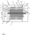
- schematically shows an arrangement, wherein cooling by an airflow takes place using an air guidance plate between an enclosure and a coil, where a large part of the insulation has been shortened longitudinally.
-
Fig. 1 shows atransformer 1, comprising an arrangement to cool acoil 2 according to the state of the art. The arrangement comprises anenclosure 3, which at least partially incorporates or houses thecoil 2 orseveral coils 2. The arrangement further comprises adevice 4 to create anairflow 5 to cool thecoil 2. Thecoil 2 comprises at least onecooling channel 6 to guide theairflow 5 through thewindings 7 of thecoil 2 and anouter air duct 8 lying radially inside below anouter part 8a of the coil. - To cool the
windings 7 of thecoil 2 of thetransformer 1, air is guided through thewindings 7. Therefore an overpressure is generated by thedevice 4 or fan at an air inlet area of theenclosure 3 of thetransformer 1. - By this means an
air flow 5 is generated to flow from the inlet towards an outlet and then through a grid into the environment. It is preferred that a large amount of air flows through thecooling channels 6 in thewindings 7. - This is generally achieved by using an
air guidance plate 9, which is arranged in close proximity to thecoil 2. By this means a flow resistance through thecooling channels 6 becomes smaller than a flow resistance around thecoil 2. This principle of the state of the art is schematically shown inFig. 1 . - This principle involves some drawbacks. In order to ensure an airflow through the
cooling channels 6, which is sufficient, an overpressure has to be generated to overcome the resistance in theenclosure 3. This requires a large effort of operation and adevice 4 having a high power. Such adevice 4 or ventilator implicates a large dimension and therefore lots of space is required for its installation. Further lots of air gets lost while flowing through theouter air duct 8. This reduces the efficiency of cooling. - To take measures, a sealing 10 is placed onto a coil surface, on which the
air guidance plate 9 is placed, so that there is no leak of airflow around the coil surface.Fig. 1 further shows, that theouter part 8a comprises aconductor 11 and that thecoil 2 comprisesbarriers 13 havinginsulations 12. -
Fig. 2 and3 each show atransformer 1', 1", comprising an arrangement to cool acoil 2 according to the invention. - To cool the
windings 7 of thecoil 2 of thetransformer 1, air is guided through thewindings 7. Therefore an overpressure is generated by the device 4' or fan at an air inlet area of theenclosure 3 of thetransformer 1. By this means anair flow 5 is generated to flow from the inlet towards an outlet and then optionally through a grid into the environment. It is preferred that a large amount of air flows through thecooling channels 6 in thewindings 7. - An underpressure at an outlet, which may be generated by a fan or an air compressor at the outlet, could also work. This means that the inlet shown in
Fig. 2 and3 also may be an outlet, which is shown by the arrow in dashed lines. Air can flow from one side to the other side of the coil. This can be reached by an overpressure or an underpressure. - The arrangement therefore comprises an
enclosure 3, which at least partially incorporates or houses at least onecoil 2, preferablyseveral coils 2. The arrangement further comprises a device 4' to create anairflow 5 to cool thecoil 5. Thecoil 2 comprises at least onecooling channel 6 to guide theairflow 5 through thewindings 7 of thecoil 2 and at least oneouter air duct 8 lying radially inside below anouter part 8a of the coil. Theouter part 8a may be an outer layer of the coil. Theouter part 8a of the coil encircles or surrounds thewindings 7. - At least one
air guidance plate 9 is placed at or near one longitudinal end of theouter air duct 8 and of thecoil 2 to prevent bypasses of theairflow 5 and to block at least partially theairflow 5 through and along theouter air duct 8. - The
air guidance plate 9 is fixed at one end or at one rim on theenclosure 3 and extends with the other end or another rim to thecoil 2, namely to the longitudinal end of theouter air duct 8. - The
air guidance plate 9 is placed onto the lower part of the high-voltage side of thecoil 2. There is a longitudinally orientedair gap 14a between theair guidance plate 9 and the high-voltage side of thecoil 2. There is also a radially orientedair gap 14b between the rim of theair guidance plate 9 and the high-voltage side of thecoil 2. -
Fig. 2 especially shows that a part of theinsulation 15 of thecoil 2, which is shown completely and not shortened inFig. 3 , is shortened to place theair guidance plate 9. -
Fig. 3 especially shows, that abarrier overhang 12 of thecoil 2 is shortened to place theair guidance plate 9, wherein theinsulation 15 is not shortened. -
Fig. 2 and3 each show atransformer 1', 1", comprising an arrangement according to the invention. Thetransformer 1', 1" is a dry-type transformer. TheTransformer 1', 1" is part of a train or is used in a rolling stock application.Reference numbers 1, 1', 1" Transformer 2 Coil of 1, 1' 3 Enclosure of 1, 1' First line voltage supply to consumers of electricity 4, 4' Device or fan 5 Airflow 6 Cooling channel of 7 7 Windings of 2 8 Outer air duct of 2 8a Outer part of 2 9 Air guidance plate 10 Sealing 11 Conductor of 8 12 Barrier overhang 13 Barrier 14a Air gap, longitudinally oriented 14b Air gap, radially oriented 15 Insulation of 8
Claims (9)
- Arrangement to cool a coil (2), comprising an enclosure (3), which at least partially incorporates or houses the coil (2), and a device (4, 4') to create an airflow (5) to cool the coil (2), wherein the coil (2) comprises at least one cooling channel (6) to guide the airflow (5) through the windings (7) of the coil (2) and an outer air duct (8) lying radially in the outer circumference area of the coil or lying radially inside below an outer part (8a) of the coil,
characterized in that an air guidance plate (9) is placed at or near one longitudinal end of the outer air duct (8) and/ or of the coil (2) to prevent bypasses of the airflow (5) and/ or to block at least partially the airflow (5) through and/or along the outer air duct (8). - Arrangement according to claim 1, characterized in that the air guidance plate (9) is fixed at one end or at one rim on the enclosure (3) and extends with the other end or another rim to the coil (2).
- Arrangement according to claim 1 or 2, characterized in that the air guidance plate (9) is placed onto the lower part of the high-voltage side of the coil (2).
- Arrangement according to one of the preceding claims, characterized in that there is at least one air gap (14a, 14b) between the air guidance plate (9) and the high-voltage side of the coil (2).
- Arrangement according to one of the preceding claims, characterized in that even a part of the insulation (15) of the lower part of the coil (2) is shortened to place the air guidance plate (9).
- Arrangement according to one of the preceding claims, characterized in that a barrier overhang (12) of the lower part of the coil (2) is shortened to place the air guidance plate (9).
- Transformer (1', 1"), comprising an arrangement according to one of the preceding claims.
- Transformer according to claim 7, which is a dry-type transformer.
- Transformer according to claim 7 or 8, which is part of a train or is used in a rolling stock application.
Priority Applications (6)
| Application Number | Priority Date | Filing Date | Title |
|---|---|---|---|
| EP19161817.2A EP3709317B1 (en) | 2019-03-11 | 2019-03-11 | Arrangement to cool a coil |
| EP22213138.5A EP4210074B1 (en) | 2019-03-11 | 2019-03-11 | Arrangement to cool a coil |
| ES19161817T ES2939715T3 (en) | 2019-03-11 | 2019-03-11 | Arrangement for cooling a coil |
| CN202080019679.2A CN113557581B (en) | 2019-03-11 | 2020-03-10 | Device for cooling coil and transformer |
| US17/438,424 US12211635B2 (en) | 2019-03-11 | 2020-03-10 | Arrangement to cool a coil |
| PCT/EP2020/056393 WO2020182835A1 (en) | 2019-03-11 | 2020-03-10 | Arrangement to cool a coil |
Applications Claiming Priority (1)
| Application Number | Priority Date | Filing Date | Title |
|---|---|---|---|
| EP19161817.2A EP3709317B1 (en) | 2019-03-11 | 2019-03-11 | Arrangement to cool a coil |
Related Child Applications (1)
| Application Number | Title | Priority Date | Filing Date |
|---|---|---|---|
| EP22213138.5A Division EP4210074B1 (en) | 2019-03-11 | 2019-03-11 | Arrangement to cool a coil |
Publications (2)
| Publication Number | Publication Date |
|---|---|
| EP3709317A1 true EP3709317A1 (en) | 2020-09-16 |
| EP3709317B1 EP3709317B1 (en) | 2023-01-04 |
Family
ID=65861201
Family Applications (2)
| Application Number | Title | Priority Date | Filing Date |
|---|---|---|---|
| EP22213138.5A Active EP4210074B1 (en) | 2019-03-11 | 2019-03-11 | Arrangement to cool a coil |
| EP19161817.2A Active EP3709317B1 (en) | 2019-03-11 | 2019-03-11 | Arrangement to cool a coil |
Family Applications Before (1)
| Application Number | Title | Priority Date | Filing Date |
|---|---|---|---|
| EP22213138.5A Active EP4210074B1 (en) | 2019-03-11 | 2019-03-11 | Arrangement to cool a coil |
Country Status (5)
| Country | Link |
|---|---|
| US (1) | US12211635B2 (en) |
| EP (2) | EP4210074B1 (en) |
| CN (1) | CN113557581B (en) |
| ES (1) | ES2939715T3 (en) |
| WO (1) | WO2020182835A1 (en) |
Cited By (1)
| Publication number | Priority date | Publication date | Assignee | Title |
|---|---|---|---|---|
| SE545022C2 (en) * | 2021-10-01 | 2023-02-28 | Bombardier Transp Gmbh | Converter system with improved cooling of magnetic components and a railway vehicle |
Families Citing this family (1)
| Publication number | Priority date | Publication date | Assignee | Title |
|---|---|---|---|---|
| CN112750607A (en) * | 2019-10-31 | 2021-05-04 | 台达电子企业管理(上海)有限公司 | Transformer and power module with same |
Citations (9)
| Publication number | Priority date | Publication date | Assignee | Title |
|---|---|---|---|---|
| US2927736A (en) * | 1954-04-23 | 1960-03-08 | Frederick S Rohatyn | Apparatus for cooling a device which produces heat during the operation thereof |
| US3500273A (en) * | 1966-12-28 | 1970-03-10 | Foster Transformer Co | Electrical transformer with heat transfer means |
| JP4980187B2 (en) * | 2007-09-25 | 2012-07-18 | 東芝三菱電機産業システム株式会社 | Transformer panel |
| US20150109081A1 (en) * | 2013-10-21 | 2015-04-23 | Hammond Power Solutions, Inc. | Cast coil assembly with fins for an electrical transformer |
| US20150256061A1 (en) * | 2012-10-19 | 2015-09-10 | Mitsubishi Electric Corporation | Inverter device, transformer, and transformer manufacturing method |
| US20160027568A1 (en) * | 2013-07-18 | 2016-01-28 | Mitsubishi Electric Corporation | Air-cooled reactor |
| CN106024298A (en) * | 2016-06-12 | 2016-10-12 | 卢国孝 | Dry-type transformer |
| JP2016219688A (en) * | 2015-05-25 | 2016-12-22 | 富士電機株式会社 | Cooler for transformer |
| CN108597762A (en) * | 2018-04-13 | 2018-09-28 | 江苏华辰变压器股份有限公司 | Novel horizontal type dry power transformer |
Family Cites Families (16)
| Publication number | Priority date | Publication date | Assignee | Title |
|---|---|---|---|---|
| US4032873A (en) * | 1976-05-21 | 1977-06-28 | The United States Of America As Represented By The United States Energy Research And Development Administration | Flow directing means for air-cooled transformers |
| JP3046477B2 (en) * | 1993-08-18 | 2000-05-29 | 株式会社東芝 | Air-cooled dry type transformer |
| JP2000232022A (en) | 1999-02-12 | 2000-08-22 | Toshiba Corp | Forced ventilation type transformer box |
| JP2001351820A (en) * | 2000-06-07 | 2001-12-21 | Mitsubishi Electric Corp | Electrical equipment |
| JP2002075749A (en) * | 2000-08-29 | 2002-03-15 | Mitsubishi Electric Corp | Induction winding device |
| EP2080202A1 (en) * | 2006-11-06 | 2009-07-22 | Abb Research Ltd. | Cooling system for a dry-type air-core reactor |
| JP5811609B2 (en) * | 2011-06-14 | 2015-11-11 | 富士電機株式会社 | Transformer cooling system |
| CN202282228U (en) * | 2011-11-09 | 2012-06-20 | 保定天威风电科技有限公司 | Dry type transformer for offshore wind power |
| CN102543394A (en) * | 2012-02-17 | 2012-07-04 | 镇江天力变压器有限公司 | Insulation member for tensioning coil of dry type transformer |
| CN102779620A (en) * | 2012-07-30 | 2012-11-14 | 华为技术有限公司 | Air-cooled radiating device of transformer |
| US9024713B1 (en) * | 2012-08-09 | 2015-05-05 | Power Distribution Products, Inc. | Extreme duty encapsulated transformer coil with corrugated cooling ducts and method of making the same |
| EP2696358B1 (en) * | 2012-08-10 | 2018-10-10 | STS Spezial-Transformatoren-Stockach GmbH & Co. KG | Medium frequency transformer |
| CN202855488U (en) * | 2012-09-28 | 2013-04-03 | 丹东欣泰电气股份有限公司 | Dry type transformer device used for offshore wind power generation |
| CN203799788U (en) * | 2014-04-03 | 2014-08-27 | 中国船舶重工集团公司第七一二研究所 | Dry-type transformer |
| WO2018170912A1 (en) * | 2017-03-24 | 2018-09-27 | Abb Schweiz Ag | Transformer with air guiding plates |
| CA3116099C (en) * | 2018-11-29 | 2024-03-26 | Yong Wang | Transformer cooling system and transformer installation |
-
2019
- 2019-03-11 ES ES19161817T patent/ES2939715T3/en active Active
- 2019-03-11 EP EP22213138.5A patent/EP4210074B1/en active Active
- 2019-03-11 EP EP19161817.2A patent/EP3709317B1/en active Active
-
2020
- 2020-03-10 CN CN202080019679.2A patent/CN113557581B/en active Active
- 2020-03-10 US US17/438,424 patent/US12211635B2/en active Active
- 2020-03-10 WO PCT/EP2020/056393 patent/WO2020182835A1/en not_active Ceased
Patent Citations (9)
| Publication number | Priority date | Publication date | Assignee | Title |
|---|---|---|---|---|
| US2927736A (en) * | 1954-04-23 | 1960-03-08 | Frederick S Rohatyn | Apparatus for cooling a device which produces heat during the operation thereof |
| US3500273A (en) * | 1966-12-28 | 1970-03-10 | Foster Transformer Co | Electrical transformer with heat transfer means |
| JP4980187B2 (en) * | 2007-09-25 | 2012-07-18 | 東芝三菱電機産業システム株式会社 | Transformer panel |
| US20150256061A1 (en) * | 2012-10-19 | 2015-09-10 | Mitsubishi Electric Corporation | Inverter device, transformer, and transformer manufacturing method |
| US20160027568A1 (en) * | 2013-07-18 | 2016-01-28 | Mitsubishi Electric Corporation | Air-cooled reactor |
| US20150109081A1 (en) * | 2013-10-21 | 2015-04-23 | Hammond Power Solutions, Inc. | Cast coil assembly with fins for an electrical transformer |
| JP2016219688A (en) * | 2015-05-25 | 2016-12-22 | 富士電機株式会社 | Cooler for transformer |
| CN106024298A (en) * | 2016-06-12 | 2016-10-12 | 卢国孝 | Dry-type transformer |
| CN108597762A (en) * | 2018-04-13 | 2018-09-28 | 江苏华辰变压器股份有限公司 | Novel horizontal type dry power transformer |
Cited By (2)
| Publication number | Priority date | Publication date | Assignee | Title |
|---|---|---|---|---|
| SE545022C2 (en) * | 2021-10-01 | 2023-02-28 | Bombardier Transp Gmbh | Converter system with improved cooling of magnetic components and a railway vehicle |
| SE2151206A1 (en) * | 2021-10-01 | 2023-02-28 | Bombardier Transp Gmbh | Converter system with improved cooling of magnetic components and a railway vehicle |
Also Published As
| Publication number | Publication date |
|---|---|
| ES2939715T3 (en) | 2023-04-26 |
| EP4210074A1 (en) | 2023-07-12 |
| CN113557581A (en) | 2021-10-26 |
| US20220148786A1 (en) | 2022-05-12 |
| EP3709317B1 (en) | 2023-01-04 |
| EP4210074B1 (en) | 2024-10-09 |
| WO2020182835A1 (en) | 2020-09-17 |
| CN113557581B (en) | 2022-12-16 |
| US12211635B2 (en) | 2025-01-28 |
Similar Documents
| Publication | Publication Date | Title |
|---|---|---|
| EP3888105B1 (en) | Transformer cooling system and transformer installation | |
| US12014856B2 (en) | Air-cooled dry-type transformer | |
| US8604899B2 (en) | Electrical transformer with diaphragm and method of cooling same | |
| US2217430A (en) | Water-cooled stator for dynamoelectric machines | |
| US8416042B2 (en) | Transformer system | |
| EP4210074B1 (en) | Arrangement to cool a coil | |
| KR20200143911A (en) | Cooling apparatus for mold type transformer | |
| US9444309B2 (en) | Radial blower air guide, system, and method of cooling | |
| JP5869093B1 (en) | control panel | |
| JP5025405B2 (en) | Cooling system for railway vehicles | |
| US10643777B2 (en) | Cooling arrangement | |
| CN215267827U (en) | Efficient motor stator tip cloth oil structure | |
| JP2008108802A (en) | Gas insulated transformer | |
| US1873989A (en) | Dynamo-electric machine ventilation | |
| JPH1022135A (en) | Stationary induction cooling system | |
| JP2016063151A (en) | Verification test apparatus and verification test method | |
| KR20230003866A (en) | A high efficiency transformer with plate type heat pipe | |
| US1001643A (en) | Dynamo-electric machine. | |
| RU181840U1 (en) | ELECTRIC BRAKE RESISTORS MODULE | |
| CN223651232U (en) | New heat dissipation device for dry-type transformers and dry-type transformers | |
| US1764305A (en) | Transformer cooling system | |
| CN114175187A (en) | Transformer cooling system | |
| CN117809936A (en) | Three-dimensional roll iron core dry-type transformer | |
| JP2003178922A (en) | Stationary induction appliance | |
| JPH08330148A (en) | Oil-filled electric machine with sound insulation wall |
Legal Events
| Date | Code | Title | Description |
|---|---|---|---|
| PUAI | Public reference made under article 153(3) epc to a published international application that has entered the european phase |
Free format text: ORIGINAL CODE: 0009012 |
|
| STAA | Information on the status of an ep patent application or granted ep patent |
Free format text: STATUS: THE APPLICATION HAS BEEN PUBLISHED |
|
| AK | Designated contracting states |
Kind code of ref document: A1 Designated state(s): AL AT BE BG CH CY CZ DE DK EE ES FI FR GB GR HR HU IE IS IT LI LT LU LV MC MK MT NL NO PL PT RO RS SE SI SK SM TR |
|
| AX | Request for extension of the european patent |
Extension state: BA ME |
|
| STAA | Information on the status of an ep patent application or granted ep patent |
Free format text: STATUS: REQUEST FOR EXAMINATION WAS MADE |
|
| 17P | Request for examination filed |
Effective date: 20210128 |
|
| RBV | Designated contracting states (corrected) |
Designated state(s): AL AT BE BG CH CY CZ DE DK EE ES FI FR GB GR HR HU IE IS IT LI LT LU LV MC MK MT NL NO PL PT RO RS SE SI SK SM TR |
|
| STAA | Information on the status of an ep patent application or granted ep patent |
Free format text: STATUS: EXAMINATION IS IN PROGRESS |
|
| 17Q | First examination report despatched |
Effective date: 20210623 |
|
| RAP3 | Party data changed (applicant data changed or rights of an application transferred) |
Owner name: HITACHI ENERGY SWITZERLAND AG |
|
| RIC1 | Information provided on ipc code assigned before grant |
Ipc: H01F 27/22 20060101ALN20220530BHEP Ipc: H01F 27/32 20060101ALI20220530BHEP Ipc: H01F 27/28 20060101ALI20220530BHEP Ipc: H01F 27/02 20060101ALI20220530BHEP Ipc: H01F 27/08 20060101AFI20220530BHEP |
|
| GRAP | Despatch of communication of intention to grant a patent |
Free format text: ORIGINAL CODE: EPIDOSNIGR1 |
|
| STAA | Information on the status of an ep patent application or granted ep patent |
Free format text: STATUS: GRANT OF PATENT IS INTENDED |
|
| INTG | Intention to grant announced |
Effective date: 20220712 |
|
| GRAS | Grant fee paid |
Free format text: ORIGINAL CODE: EPIDOSNIGR3 |
|
| GRAA | (expected) grant |
Free format text: ORIGINAL CODE: 0009210 |
|
| STAA | Information on the status of an ep patent application or granted ep patent |
Free format text: STATUS: THE PATENT HAS BEEN GRANTED |
|
| RIN1 | Information on inventor provided before grant (corrected) |
Inventor name: WENG, JIAHUA Inventor name: TEPPER, JENS Inventor name: WANG, YONG |
|
| AK | Designated contracting states |
Kind code of ref document: B1 Designated state(s): AL AT BE BG CH CY CZ DE DK EE ES FI FR GB GR HR HU IE IS IT LI LT LU LV MC MK MT NL NO PL PT RO RS SE SI SK SM TR |
|
| REG | Reference to a national code |
Ref country code: GB Ref legal event code: FG4D |
|
| REG | Reference to a national code |
Ref country code: CH Ref legal event code: EP |
|
| REG | Reference to a national code |
Ref country code: AT Ref legal event code: REF Ref document number: 1542529 Country of ref document: AT Kind code of ref document: T Effective date: 20230115 |
|
| REG | Reference to a national code |
Ref country code: DE Ref legal event code: R096 Ref document number: 602019023849 Country of ref document: DE |
|
| REG | Reference to a national code |
Ref country code: IE Ref legal event code: FG4D |
|
| REG | Reference to a national code |
Ref country code: SE Ref legal event code: TRGR |
|
| REG | Reference to a national code |
Ref country code: LT Ref legal event code: MG9D |
|
| REG | Reference to a national code |
Ref country code: ES Ref legal event code: FG2A Ref document number: 2939715 Country of ref document: ES Kind code of ref document: T3 Effective date: 20230426 |
|
| REG | Reference to a national code |
Ref country code: NL Ref legal event code: MP Effective date: 20230104 |
|
| PG25 | Lapsed in a contracting state [announced via postgrant information from national office to epo] |
Ref country code: NL Free format text: LAPSE BECAUSE OF FAILURE TO SUBMIT A TRANSLATION OF THE DESCRIPTION OR TO PAY THE FEE WITHIN THE PRESCRIBED TIME-LIMIT Effective date: 20230104 |
|
| P01 | Opt-out of the competence of the unified patent court (upc) registered |
Effective date: 20230527 |
|
| PG25 | Lapsed in a contracting state [announced via postgrant information from national office to epo] |
Ref country code: RS Free format text: LAPSE BECAUSE OF FAILURE TO SUBMIT A TRANSLATION OF THE DESCRIPTION OR TO PAY THE FEE WITHIN THE PRESCRIBED TIME-LIMIT Effective date: 20230104 Ref country code: PT Free format text: LAPSE BECAUSE OF FAILURE TO SUBMIT A TRANSLATION OF THE DESCRIPTION OR TO PAY THE FEE WITHIN THE PRESCRIBED TIME-LIMIT Effective date: 20230504 Ref country code: NO Free format text: LAPSE BECAUSE OF FAILURE TO SUBMIT A TRANSLATION OF THE DESCRIPTION OR TO PAY THE FEE WITHIN THE PRESCRIBED TIME-LIMIT Effective date: 20230404 Ref country code: LV Free format text: LAPSE BECAUSE OF FAILURE TO SUBMIT A TRANSLATION OF THE DESCRIPTION OR TO PAY THE FEE WITHIN THE PRESCRIBED TIME-LIMIT Effective date: 20230104 Ref country code: LT Free format text: LAPSE BECAUSE OF FAILURE TO SUBMIT A TRANSLATION OF THE DESCRIPTION OR TO PAY THE FEE WITHIN THE PRESCRIBED TIME-LIMIT Effective date: 20230104 Ref country code: HR Free format text: LAPSE BECAUSE OF FAILURE TO SUBMIT A TRANSLATION OF THE DESCRIPTION OR TO PAY THE FEE WITHIN THE PRESCRIBED TIME-LIMIT Effective date: 20230104 |
|
| PG25 | Lapsed in a contracting state [announced via postgrant information from national office to epo] |
Ref country code: PL Free format text: LAPSE BECAUSE OF FAILURE TO SUBMIT A TRANSLATION OF THE DESCRIPTION OR TO PAY THE FEE WITHIN THE PRESCRIBED TIME-LIMIT Effective date: 20230104 Ref country code: IS Free format text: LAPSE BECAUSE OF FAILURE TO SUBMIT A TRANSLATION OF THE DESCRIPTION OR TO PAY THE FEE WITHIN THE PRESCRIBED TIME-LIMIT Effective date: 20230504 Ref country code: GR Free format text: LAPSE BECAUSE OF FAILURE TO SUBMIT A TRANSLATION OF THE DESCRIPTION OR TO PAY THE FEE WITHIN THE PRESCRIBED TIME-LIMIT Effective date: 20230405 Ref country code: FI Free format text: LAPSE BECAUSE OF FAILURE TO SUBMIT A TRANSLATION OF THE DESCRIPTION OR TO PAY THE FEE WITHIN THE PRESCRIBED TIME-LIMIT Effective date: 20230104 |
|
| REG | Reference to a national code |
Ref country code: DE Ref legal event code: R097 Ref document number: 602019023849 Country of ref document: DE |
|
| PG25 | Lapsed in a contracting state [announced via postgrant information from national office to epo] |
Ref country code: SM Free format text: LAPSE BECAUSE OF FAILURE TO SUBMIT A TRANSLATION OF THE DESCRIPTION OR TO PAY THE FEE WITHIN THE PRESCRIBED TIME-LIMIT Effective date: 20230104 Ref country code: RO Free format text: LAPSE BECAUSE OF FAILURE TO SUBMIT A TRANSLATION OF THE DESCRIPTION OR TO PAY THE FEE WITHIN THE PRESCRIBED TIME-LIMIT Effective date: 20230104 Ref country code: MC Free format text: LAPSE BECAUSE OF FAILURE TO SUBMIT A TRANSLATION OF THE DESCRIPTION OR TO PAY THE FEE WITHIN THE PRESCRIBED TIME-LIMIT Effective date: 20230104 Ref country code: EE Free format text: LAPSE BECAUSE OF FAILURE TO SUBMIT A TRANSLATION OF THE DESCRIPTION OR TO PAY THE FEE WITHIN THE PRESCRIBED TIME-LIMIT Effective date: 20230104 Ref country code: DK Free format text: LAPSE BECAUSE OF FAILURE TO SUBMIT A TRANSLATION OF THE DESCRIPTION OR TO PAY THE FEE WITHIN THE PRESCRIBED TIME-LIMIT Effective date: 20230104 Ref country code: CZ Free format text: LAPSE BECAUSE OF FAILURE TO SUBMIT A TRANSLATION OF THE DESCRIPTION OR TO PAY THE FEE WITHIN THE PRESCRIBED TIME-LIMIT Effective date: 20230104 |
|
| PLBE | No opposition filed within time limit |
Free format text: ORIGINAL CODE: 0009261 |
|
| STAA | Information on the status of an ep patent application or granted ep patent |
Free format text: STATUS: NO OPPOSITION FILED WITHIN TIME LIMIT |
|
| PG25 | Lapsed in a contracting state [announced via postgrant information from national office to epo] |
Ref country code: SK Free format text: LAPSE BECAUSE OF FAILURE TO SUBMIT A TRANSLATION OF THE DESCRIPTION OR TO PAY THE FEE WITHIN THE PRESCRIBED TIME-LIMIT Effective date: 20230104 |
|
| REG | Reference to a national code |
Ref country code: BE Ref legal event code: MM Effective date: 20230331 |
|
| 26N | No opposition filed |
Effective date: 20231005 |
|
| REG | Reference to a national code |
Ref country code: AT Ref legal event code: UEP Ref document number: 1542529 Country of ref document: AT Kind code of ref document: T Effective date: 20230104 |
|
| PG25 | Lapsed in a contracting state [announced via postgrant information from national office to epo] |
Ref country code: LU Free format text: LAPSE BECAUSE OF NON-PAYMENT OF DUE FEES Effective date: 20230311 |
|
| REG | Reference to a national code |
Ref country code: IE Ref legal event code: MM4A |
|
| PG25 | Lapsed in a contracting state [announced via postgrant information from national office to epo] |
Ref country code: SI Free format text: LAPSE BECAUSE OF FAILURE TO SUBMIT A TRANSLATION OF THE DESCRIPTION OR TO PAY THE FEE WITHIN THE PRESCRIBED TIME-LIMIT Effective date: 20230104 Ref country code: IE Free format text: LAPSE BECAUSE OF NON-PAYMENT OF DUE FEES Effective date: 20230311 |
|
| PG25 | Lapsed in a contracting state [announced via postgrant information from national office to epo] |
Ref country code: BE Free format text: LAPSE BECAUSE OF NON-PAYMENT OF DUE FEES Effective date: 20230331 |
|
| REG | Reference to a national code |
Ref country code: DE Ref legal event code: R081 Ref document number: 602019023849 Country of ref document: DE Owner name: HITACHI ENERGY LTD, CH Free format text: FORMER OWNER: HITACHI ENERGY SWITZERLAND AG, BADEN, CH |
|
| REG | Reference to a national code |
Ref country code: AT Ref legal event code: PC Ref document number: 1542529 Country of ref document: AT Kind code of ref document: T Owner name: HITACHI ENERGY LTD, CH Effective date: 20240416 |
|
| REG | Reference to a national code |
Ref country code: GB Ref legal event code: 732E Free format text: REGISTERED BETWEEN 20240718 AND 20240724 |
|
| REG | Reference to a national code |
Ref country code: ES Ref legal event code: PC2A Owner name: HITACHI ENERGY LTD Effective date: 20240925 |
|
| PG25 | Lapsed in a contracting state [announced via postgrant information from national office to epo] |
Ref country code: BG Free format text: LAPSE BECAUSE OF FAILURE TO SUBMIT A TRANSLATION OF THE DESCRIPTION OR TO PAY THE FEE WITHIN THE PRESCRIBED TIME-LIMIT Effective date: 20230104 |
|
| PG25 | Lapsed in a contracting state [announced via postgrant information from national office to epo] |
Ref country code: BG Free format text: LAPSE BECAUSE OF FAILURE TO SUBMIT A TRANSLATION OF THE DESCRIPTION OR TO PAY THE FEE WITHIN THE PRESCRIBED TIME-LIMIT Effective date: 20230104 |
|
| REG | Reference to a national code |
Ref country code: DE Ref legal event code: R082 Ref document number: 602019023849 Country of ref document: DE Representative=s name: DENNEMEYER & ASSOCIATES RECHTSANWALTSGESELLSCH, DE |
|
| PGFP | Annual fee paid to national office [announced via postgrant information from national office to epo] |
Ref country code: ES Payment date: 20250429 Year of fee payment: 7 |
|
| PGFP | Annual fee paid to national office [announced via postgrant information from national office to epo] |
Ref country code: CH Payment date: 20250401 Year of fee payment: 7 |
|
| PG25 | Lapsed in a contracting state [announced via postgrant information from national office to epo] |
Ref country code: CY Free format text: LAPSE BECAUSE OF FAILURE TO SUBMIT A TRANSLATION OF THE DESCRIPTION OR TO PAY THE FEE WITHIN THE PRESCRIBED TIME-LIMIT; INVALID AB INITIO Effective date: 20190311 |
|
| PG25 | Lapsed in a contracting state [announced via postgrant information from national office to epo] |
Ref country code: HU Free format text: LAPSE BECAUSE OF FAILURE TO SUBMIT A TRANSLATION OF THE DESCRIPTION OR TO PAY THE FEE WITHIN THE PRESCRIBED TIME-LIMIT; INVALID AB INITIO Effective date: 20190311 |
|
| REG | Reference to a national code |
Ref country code: CH Ref legal event code: U11 Free format text: ST27 STATUS EVENT CODE: U-0-0-U10-U11 (AS PROVIDED BY THE NATIONAL OFFICE) Effective date: 20260401 |
|
| PGFP | Annual fee paid to national office [announced via postgrant information from national office to epo] |
Ref country code: SE Payment date: 20260319 Year of fee payment: 8 |
|
| PGFP | Annual fee paid to national office [announced via postgrant information from national office to epo] |
Ref country code: GB Payment date: 20260324 Year of fee payment: 8 |
|
| PGFP | Annual fee paid to national office [announced via postgrant information from national office to epo] |
Ref country code: DE Payment date: 20260319 Year of fee payment: 8 |
|
| PGFP | Annual fee paid to national office [announced via postgrant information from national office to epo] |
Ref country code: AT Payment date: 20260320 Year of fee payment: 8 |
|
| PGFP | Annual fee paid to national office [announced via postgrant information from national office to epo] |
Ref country code: IT Payment date: 20260324 Year of fee payment: 8 |
|
| PGFP | Annual fee paid to national office [announced via postgrant information from national office to epo] |
Ref country code: FR Payment date: 20260320 Year of fee payment: 8 |
|
| PGFP | Annual fee paid to national office [announced via postgrant information from national office to epo] |
Ref country code: TR Payment date: 20260304 Year of fee payment: 8 |