ES2939715T3 - Arrangement for cooling a coil - Google Patents
Arrangement for cooling a coil Download PDFInfo
- Publication number
- ES2939715T3 ES2939715T3 ES19161817T ES19161817T ES2939715T3 ES 2939715 T3 ES2939715 T3 ES 2939715T3 ES 19161817 T ES19161817 T ES 19161817T ES 19161817 T ES19161817 T ES 19161817T ES 2939715 T3 ES2939715 T3 ES 2939715T3
- Authority
- ES
- Spain
- Prior art keywords
- coil
- air
- transformer
- cooling
- flow
- Prior art date
- Legal status (The legal status is an assumption and is not a legal conclusion. Google has not performed a legal analysis and makes no representation as to the accuracy of the status listed.)
- Active
Links
- 238000001816 cooling Methods 0.000 title claims abstract description 35
- 238000004804 winding Methods 0.000 claims abstract description 21
- 238000009413 insulation Methods 0.000 claims description 8
- 230000004888 barrier function Effects 0.000 claims description 5
- 238000005096 rolling process Methods 0.000 claims description 3
- 238000009434 installation Methods 0.000 description 2
- 238000005259 measurement Methods 0.000 description 2
- 239000004020 conductor Substances 0.000 description 1
- 239000000428 dust Substances 0.000 description 1
- 238000007789 sealing Methods 0.000 description 1
- 238000004904 shortening Methods 0.000 description 1
Classifications
-
- H—ELECTRICITY
- H01—ELECTRIC ELEMENTS
- H01F—MAGNETS; INDUCTANCES; TRANSFORMERS; SELECTION OF MATERIALS FOR THEIR MAGNETIC PROPERTIES
- H01F27/00—Details of transformers or inductances, in general
- H01F27/08—Cooling; Ventilating
- H01F27/085—Cooling by ambient air
-
- H—ELECTRICITY
- H01—ELECTRIC ELEMENTS
- H01F—MAGNETS; INDUCTANCES; TRANSFORMERS; SELECTION OF MATERIALS FOR THEIR MAGNETIC PROPERTIES
- H01F27/00—Details of transformers or inductances, in general
- H01F27/02—Casings
- H01F27/025—Constructional details relating to cooling
-
- H—ELECTRICITY
- H01—ELECTRIC ELEMENTS
- H01F—MAGNETS; INDUCTANCES; TRANSFORMERS; SELECTION OF MATERIALS FOR THEIR MAGNETIC PROPERTIES
- H01F27/00—Details of transformers or inductances, in general
- H01F27/06—Mounting, supporting or suspending transformers, reactors or choke coils not being of the signal type
-
- H—ELECTRICITY
- H01—ELECTRIC ELEMENTS
- H01F—MAGNETS; INDUCTANCES; TRANSFORMERS; SELECTION OF MATERIALS FOR THEIR MAGNETIC PROPERTIES
- H01F27/00—Details of transformers or inductances, in general
- H01F27/28—Coils; Windings; Conductive connections
- H01F27/2876—Cooling
-
- H—ELECTRICITY
- H01—ELECTRIC ELEMENTS
- H01F—MAGNETS; INDUCTANCES; TRANSFORMERS; SELECTION OF MATERIALS FOR THEIR MAGNETIC PROPERTIES
- H01F27/00—Details of transformers or inductances, in general
- H01F27/28—Coils; Windings; Conductive connections
- H01F27/32—Insulating of coils, windings, or parts thereof
- H01F27/322—Insulating of coils, windings, or parts thereof the insulation forming channels for circulation of the fluid
Abstract
Disposición para enfriar un serpentín (2), que comprende un recinto (3), que incorpora o aloja al menos parcialmente el serpentín (2), y un dispositivo (4, 4') para crear un flujo de aire (5) para enfriar el serpentín. (2), donde el serpentín (2) comprende al menos un canal de refrigeración (6) para guiar el flujo de aire (5) a través de los devanados (7) del serpentín (2) y un conducto de aire exterior (8) que se encuentra radialmente en el circunferencia exterior del serpentín o situada radialmente en el interior por debajo de una parte exterior (8a) del serpentín, caracterizada porque se coloca una placa de conducción de aire (9) en o cerca de un extremo longitudinal del conducto de aire exterior (8) y/o del serpentín (2) para evitar desvíos del flujo de aire (5) y/o para bloquear al menos parcialmente el flujo de aire (5) a través y/o a lo largo del conducto de aire exterior (8), logra el objetivo de enfriar un serpentín, especialmente una bobina de un transformador,de manera eficiente utilizando medios que ahorran espacio. (Traducción automática con Google Translate, sin valor legal)Arrangement for cooling a coil (2), comprising an enclosure (3), which at least partially incorporates or houses the coil (2), and a device (4, 4') for creating an air flow (5) for cooling the coil. (2), where the coil (2) comprises at least one cooling channel (6) to guide the air flow (5) through the windings (7) of the coil (2) and an outside air duct (8 ) which is located radially on the outer circumference of the coil or located radially inside below an outer part (8a) of the coil, characterized in that an air conduction plate (9) is placed at or near a longitudinal end of the coil. outdoor air duct (8) and/or coil (2) to prevent diversions of the air flow (5) and/or to at least partially block the air flow (5) through and/or along the air duct outdoor air (8), achieves the goal of cooling a coil, especially a transformer coil, efficiently using space-saving means. (Automatic translation with Google Translate, without legal value)
Description
DESCRIPCIÓNDESCRIPTION
Disposición para enfriar una bobinaArrangement for cooling a coil
La invención se refiere a una disposición para enfriar una bobina, que comprende un recinto, que al menos parcialmente incorpora o aloja la bobina, y un dispositivo para crear un flujo de aire para enfriar la bobina, en donde la bobina comprende al menos un canal de enfriamiento para guiar el flujo de aire a través de los devanados de la bobina y un conducto de aire exterior que pasa radialmente dentro de una parte exterior de la bobina.The invention relates to an arrangement for cooling a coil, comprising an enclosure, which at least partially incorporates or houses the coil, and a device for creating a flow of air to cool the coil, wherein the coil comprises at least one channel. cooling for guiding airflow through the coil windings and an outside air duct passing radially into an outer part of the coil.
Es conocido enfriar los devanados de una bobina de un transformador guiando aire a través de sus devanados. Por lo tanto, un extractor genera una sobrepresión en un área de entrada de aire de un recinto del transformador. De esta manera se genera un flujo de aire que fluye desde la entrada hacia una salida y luego a través de una rejilla hacia el ambiente.It is known to cool the windings of a transformer coil by guiding air through its windings. Therefore, an exhaust fan generates an overpressure in an air inlet area of a transformer enclosure. In this way, an air flow is generated that flows from the entrance to an exit and then through a grill to the environment.
Se prefiere que fluya una gran cantidad de aire a través de los canales de enfriamiento en los devanados. Esto se logra generalmente mediante el uso de placas de conducción de aire que se disponen muy cerca de las bobinas. De este modo, la resistencia al flujo a través de los canales de enfriamiento se vuelve más pequeña que la resistencia al flujo alrededor de las bobinas. Este principio del estado de la técnica se muestra esquemáticamente en la figura 1. Este principio implica algunos inconvenientes. Para garantizar un flujo de aire a través de los canales de enfriamiento, que sea suficiente, se debe generar una sobrepresión para vencer la resistencia en el recinto.It is preferred that a large amount of air flows through the cooling channels in the windings. This is generally accomplished through the use of air guide plates that are arranged in close proximity to the coils. Thus, the resistance to flow through the cooling channels becomes smaller than the resistance to flow around the coils. This principle of the state of the art is shown schematically in figure 1. This principle involves some drawbacks. To ensure sufficient airflow through the cooling channels, an overpressure must be generated to overcome the resistance in the enclosure.
Esto requiere un gran esfuerzo de operación y un ventilador de alta potencia. Un ventilador de este tipo implica una gran dimensión y, por lo tanto, se requiere mucho espacio para su instalación. Más cantidad de aire fluye de manera ineficaz a través de un conducto de aire exterior. Esto reduce la eficacia del enfriamiento. Para tomar medidas, a menudo se coloca un sellado sobre esa superficie de la bobina, superficie sobre la que se coloca la placa de conducción de aire, de modo que no haya fugas de flujo de aire alrededor de la superficie de la bobina.This requires a lot of effort to operate and a high powered fan. Such a fan involves a large dimension and therefore a lot of space is required for its installation. More air flows inefficiently through an outdoor air duct. This reduces the effectiveness of the cooling. To take measurements, a seal is often placed on that surface of the coil, the surface on which the air guide plate is placed, so that there is no airflow leakage around the surface of the coil.
En el documento CN 108 597 762 A se describe un transformador de potencia de tipo seco. En el documento JP 2016219688 A se hace referencia a un enfriador para un transformador. En el documento JP 4980 187 B2 se describe una placa de transformador. En el documento US 2 927 736 A se hace referencia a un aparato para enfriar un dispositivo que produce calor durante la operación del mismo. En el documento US 2016/027568 A1 se describe un reactor enfriado por aire.In CN 108 597 762 A a dry type power transformer is described. In JP 2016219688 A reference is made to a cooler for a transformer. In JP 4980 187 B2 a transformer plate is described. In US 2 927 736 A reference is made to an apparatus for cooling a device that produces heat during operation thereof. In US 2016/027568 A1 an air-cooled reactor is described.
Por lo tanto, el objeto de la invención es enfriar una bobina, especialmente una bobina de un transformador, de manera eficaz usando medios que ahorran espacio.Therefore, the object of the invention is to cool a coil, especially a coil of a transformer, efficiently using space-saving means.
El objeto de la invención se consigue mediante las características de la reivindicación 1. Según esta reivindicación, se coloca una placa de conducción de aire en un extremo longitudinal del conducto de aire exterior y de la bobina para bloquear al menos parcialmente el flujo de aire a través del conducto de aire exterior y/o a lo largo de este.The object of the invention is achieved by the features of claim 1. According to this claim, an air conduction plate is placed at a longitudinal end of the outdoor air duct and the coil to at least partially block the flow of air through through and/or along the outdoor air duct.
Según la invención, se ha encontrado que una placa de conducción de aire debe colocarse de una manera diferente a la del estado de la técnica. La presente invención se refiere a un posicionamiento especial de al menos una placa de conducción de aire. Según la invención, mediante este posicionamiento, el conducto de aire exterior se bloquea hasta un grado deseado, de modo que el aire para enfriar fluye principalmente a través de los canales de enfriamiento de los devanados. El resultado es una mayor eficacia de enfriamiento. Debido a la mayor eficacia de enfriamiento, se pueden usar extractores o ventiladores de menor potencia. El dispositivo para crear un flujo de aire puede ser compacto y ahorrar espacio.According to the invention, it has been found that an air guide plate must be positioned in a different way than in the prior art. The present invention relates to a special positioning of at least one air guide plate. According to the invention, by this positioning, the outside air duct is blocked to a desired degree, so that the air for cooling flows mainly through the cooling channels of the windings. The result is greater cooling efficiency. Due to the higher cooling efficiency, lower power exhaust fans or fans can be used. The device for creating an air flow can be compact and save space.
Ventajosamente, la placa de conducción de aire está fijada por un extremo o por un reborde sobre el recinto y se prolonga por el otro extremo o por otro reborde hasta la bobina. De esta forma se eliminan los sellados en la bobina y/o en el recinto y la mano de obra correspondiente para su montaje. Además, la resistencia al flujo a través de los canales de enfriamiento se vuelve más pequeña que la resistencia al flujo fuera de la bobina.Advantageously, the air guide plate is attached at one end or a flange to the enclosure and extends at the other end or another flange as far as the coil. In this way, the seals in the coil and/or in the enclosure and the corresponding labor for its assembly are eliminated. Also, the resistance to flow through the cooling channels becomes smaller than the resistance to flow out of the coil.
Además, ventajosamente, la placa de conducción de aire se coloca directamente sobre la parte inferior del lado de alto voltaje de la bobina. El lado de alto voltaje es el lado del devanado de alto voltaje de una bobina de un transformador. La parte inferior está menos solicitada con respecto a las tensiones dieléctricas. Hasta la fecha, la parte inferior también puede denominarse la parte fría de la bobina. El devanado de alto voltaje está conectado a tierra en un lado, es decir, en la parte fría. Por lo tanto, la placa de conducción de aire puede disponerse fácil y directamente en la parte fría del devanado de alto voltaje. De este modo, la resistencia al flujo a través de los canales de enfriamiento se vuelve menor que la resistencia al flujo fuera de la bobina.Furthermore, advantageously, the air conduction plate is placed directly on the underside of the high voltage side of the coil. The high voltage side is the high voltage winding side of a transformer coil. The lower part is less stressed with respect to dielectric stresses. To date, the lower part can also be called the cold part of the coil. The high voltage winding is grounded on one side, that is, on the cold part. Therefore, the air conduction plate can be easily and directly arranged in the cold part of the high voltage winding. Thus, the resistance to flow through the cooling channels becomes less than the resistance to flow out of the coil.
Además, el conducto de aire exterior que se encuentra radialmente en el interior por debajo de la superficie exterior de la bobina se puede bloquear hasta el grado deseado, de modo que el flujo de aire a través de los canales de enfriamiento en los devanados se vuelve más eficaz.In addition, the outside air duct which is radially inside below the outside surface of the coil can be blocked to the desired degree, so that the air flow through the cooling channels in the windings becomes more effective.
Ventajosamente, existe al menos un espacio de aire entre la placa de conducción de aire y el lado de alto voltaje de la bobina. Por este medio no se tiene que usar ningún sellado en la superficie de la bobina. Se pueden ahorrar costes de sellado. Además, el conducto de aire exterior que se encuentra radialmente en el interior por debajo de la superficie exterior de la bobina se puede bloquear hasta el grado deseado de tal manera que el flujo de aire a través de los canales de enfriamiento en los devanados se vuelve más eficaz. La tolerancia dimensional de la placa de conducción de aire adaptada es mayor, porque se permite o se desea un espacio de aire entre una superficie de la bobina y una placa de conducción de aire. Un pequeño espacio de aire entre la bobina y la placa de conducción de aire también permite el flujo de polvo a través del conducto de aire exterior.Advantageously, there is at least one air gap between the air guide plate and the high voltage side of the coil. By this means no seal has to be used on the coil surface. Sealing costs can be saved. In addition, the outside air duct which is located radially inside below the surface The coil's exterior can be blocked to the desired degree in such a way that the airflow through the cooling channels in the windings becomes more effective. The dimensional tolerance of the adapted air guide plate is larger, because an air gap between a coil surface and an air guide plate is allowed or desired. A small air gap between the coil and the air guide plate also allows dust to flow through the outside air duct.
Además, se acorta una parte del aislamiento de la parte inferior de la bobina para colocar la placa de conducción de aire. Acortando longitudinalmente una parte del aislamiento en la parte inferior de la bobina, la placa de conducción de aire se puede colocar directamente en el lado de alto voltaje de la bobina.In addition, a part of the insulation at the bottom of the coil is shortened to accommodate the air conduction plate. By lengthwise shortening a part of the insulation at the bottom of the coil, the air conduction plate can be placed directly on the high voltage side of the coil.
El recinto descrito anteriormente es preferiblemente el recinto de un transformador, en donde se alojan varias bobinas en el recinto. El dispositivo para crear un flujo de aire se puede colocar al lado y/o fuera del recinto o dentro del recinto. The enclosure described above is preferably the enclosure of a transformer, where several coils are housed in the enclosure. The device for creating an air flow can be placed next to and/or outside the enclosure or inside the enclosure.
Por lo tanto, un transformador comprende la disposición descrita anteriormente. El transformador puede estar encerrado en el recinto con enfriamiento por aire forzado. El transformador puede comprender varias bobinas, especialmente tres bobinas. Cada bobina está equipada con una o más placas de conducción de aire como se describió anteriormente.Therefore, a transformer comprises the arrangement described above. The transformer may be enclosed in the enclosure with forced air cooling. The transformer can comprise several coils, especially three coils. Each coil is equipped with one or more air guide plates as described above.
El transformador es un transformador de tipo seco. Especialmente, el transformador es un transformador de tipo seco para aplicaciones de material rodante. El transformador se usa preferiblemente en un tren. El transformador de tipo seco está en un recinto con enfriamiento por aire forzado.The transformer is a dry type transformer. Especially, the transformer is a dry type transformer for rolling stock applications. The transformer is preferably used in a train. The dry type transformer is in a forced air cooled enclosure.
En los dibujos:In the drawings:
Fig. 1 Muestra esquemáticamente un disposición según el estado de la técnica, en donde el enfriamiento por un flujo de aire se realiza mediante una placa de conducción de aire, que se coloca radialmente entre un recinto y un conducto de aire exterior.Fig. 1 schematically shows an arrangement according to the state of the art, in which cooling by an air flow is carried out by means of an air guide plate, which is placed radially between a room and an outside air duct.
Fig. 2 Muestra esquemáticamente un disposición, en donde el enfriamiento por un flujo de aire tiene lugar usando una placa de conducción de aire entre un recinto y una bobina, donde una parte del aislamiento se ha acortado longitudinalmente.Fig. 2 Schematically shows an arrangement, where cooling by an air flow takes place using an air conduction plate between an enclosure and a coil, where a part of the insulation has been shortened lengthwise.
Fig. 3 Muestra esquemáticamente un ejemplo no cubierto por las reivindicaciones, en donde el enfriamiento por un flujo de aire tiene lugar usando una placa de conducción de aire entre un recinto y una bobina, donde el aislamiento no se ha acortado.Fig. 3 Schematically shows an example not covered by the claims, where cooling by an air flow takes place using an air conduction plate between an enclosure and a coil, where the insulation has not been shortened.
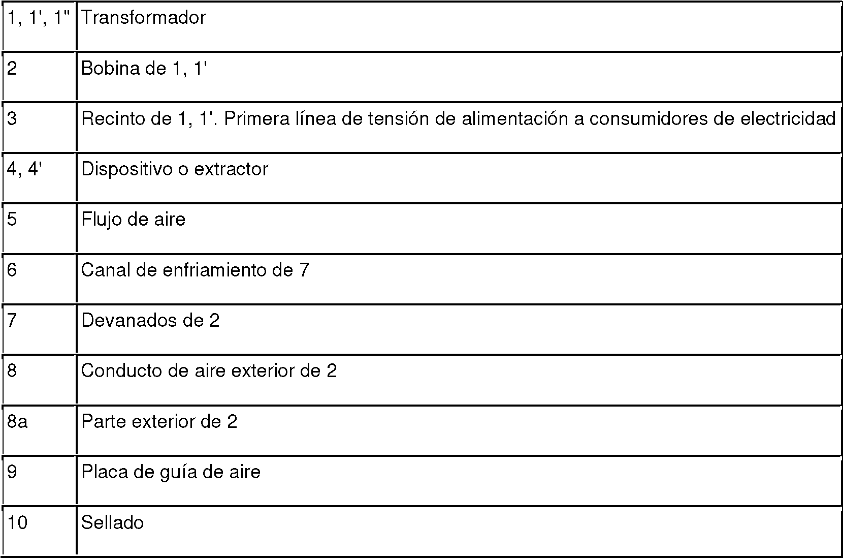
La figura 1 muestra un transformador 1 que comprende un disposición para enfriar una bobina 2 según el estado de la técnica. La disposición comprende un recinto 3, que al menos parcialmente incorpora o aloja la bobina 2 o varias bobinas 2. La disposición comprende además un dispositivo 4 para crear un flujo 5 de aire para enfriar la bobina 2. La bobina 2 comprende al menos un canal 6 de enfriamiento para guiar el flujo 5 de aire a través de los devanados 7 de la bobina 2 y un conducto 8 de aire exterior que se encuentra radialmente en el interior por debajo de una parte 8a exterior de la bobina.Figure 1 shows a transformer 1 comprising an arrangement for cooling a coil 2 according to the state of the art. The arrangement comprises an enclosure 3, which at least partially incorporates or houses the coil 2 or several coils 2. The arrangement further comprises a device 4 for creating an air flow 5 to cool the coil 2. The coil 2 comprises at least one channel 6 for guiding the flow 5 of air through the windings 7 of the coil 2 and an outside air duct 8 which lies radially inside below an outside part 8a of the coil.
Para enfriar los devanados 7 de la bobina 2 del transformador 1, se conduce aire a través de los devanados 7. Por lo tanto, el dispositivo 4 o extractor genera una sobrepresión en un área de entrada de aire del recinto 3 del transformador 1.In order to cool the windings 7 of the coil 2 of the transformer 1, air is conducted through the windings 7. Therefore, the device 4 or extractor generates an overpressure in an air inlet area of the enclosure 3 of the transformer 1.
De esta manera se genera un flujo 5 de aire que fluye desde la entrada hacia una salida y luego a través de una rejilla hacia el ambiente. Se prefiere que una gran cantidad de aire fluya a través de los canales 6 de enfriamiento en los devanados 7.In this way a flow 5 of air is generated which flows from the inlet to an outlet and then through a grille into the environment. It is preferred that a large amount of air flows through the cooling channels 6 in the windings 7.
En general, esto se logra mediante el uso de una placa 9 de conducción de aire, que está dispuesta muy cerca de la bobina 2. De este modo, la resistencia al flujo a través de los canales 6 de enfriamiento se vuelve más pequeña que la resistencia al flujo alrededor de la bobina 2. Este principio del estado de la técnica se muestra esquemáticamente en la Fig. 1.In general, this is achieved by using an air conduction plate 9, which is arranged very close to the coil 2. Thus, the resistance to flow through the cooling channels 6 becomes smaller than the resistance to flow around the coil 2. This principle of the state of the art is shown schematically in Fig. 1.
Este principio implica algunos inconvenientes. Para asegurar un flujo de aire a través de los canales 6 de enfriamiento, que sea suficiente, se debe generar una sobrepresión para vencer la resistencia en el recinto 3. Esto requiere un gran esfuerzo de operación y un dispositivo 4 que tenga una alta potencia. Tal dispositivo 4 o ventilador implica una gran dimensión y por lo tanto se requiere mucho espacio para su instalación. Se pierden más cantidades de aire mientras fluye a través del conducto 8 de aire exterior. Esto reduce la eficacia del enfriamiento.This principle involves some drawbacks. In order to ensure a sufficient airflow through the cooling channels 6, an overpressure must be generated to overcome the resistance in the enclosure 3. This requires a large operating effort and a device 4 having a high power. Such a device 4 or fan involves a large dimension and therefore a lot of space is required for its installation. Further amounts of air are lost while flowing through the outside air duct 8. This reduces the effectiveness of the cooling.
Para tomar medidas, se coloca un sello 10 sobre la superficie de una bobina, sobre la cual se coloca la placa 9 de conducción de aire, de modo que no haya fugas de flujo de aire alrededor de la superficie de la bobina. La figura 1 muestra además que la parte 8a exterior comprende un conductor 11 y que la bobina 2 comprende barreras 13 que tienen un voladizo 12 de barrera.For taking measurements, a seal 10 is placed on the surface of a coil, on which the air conduction plate 9 is placed, so that there is no airflow leakage around the coil surface. Figure 1 further shows that the outer part 8a comprises a conductor 11 and that the coil 2 comprises barriers 13 having a barrier overhang 12.
La figura 2 muestra un transformador 1' que comprende un disposición para enfriar una bobina 2 según la invención. Figure 2 shows a transformer 1' comprising an arrangement for cooling a coil 2 according to the invention.
Para enfriar los devanados 7 de la bobina 2 del transformador 1, se conduce aire a través de los devanados 7. Por lo tanto, el dispositivo 4' o extractor genera una sobrepresión en un área de entrada de aire del recinto 3 del transformador 1. Por este medio se genera un flujo 5 de aire que fluye desde la entrada hacia una salida y luego, opcionalmente, a través de una rejilla hacia el ambiente. Se prefiere que una gran cantidad de aire fluya a través de los canales 6 de enfriamiento en los devanados 7.In order to cool the windings 7 of the coil 2 of the transformer 1, air is conducted through the windings 7. Therefore, the device 4' or extractor generates an overpressure in an air inlet area of the enclosure 3 of the transformer 1. By this means an air flow 5 is generated which flows from the inlet to an outlet and then, optionally, through a grill to the environment. It is preferred that a large amount of air flows through the cooling channels 6 in the windings 7.
También podría funcionar una subpresión en una salida, que puede ser generada por un extractor o un compresor de aire en la salida. Esto significa que la entrada que se muestra en las figuras 2 y 3 también puede ser una salida, que se muestra con la flecha en líneas discontinuas. El aire puede fluir de un lado al otro lado de la bobina. Esto se puede alcanzar mediante una sobrepresión o una subpresión.An underpressure at an outlet could also operate, which can be generated by an exhaust fan or air compressor at the outlet. This means that the input shown in Figures 2 and 3 can also be an output, shown by the dashed arrow. Air can flow from one side of the coil to the other side. This can be achieved by overpressure or underpressure.
Por lo tanto, la disposición comprende un recinto 3, que al menos parcialmente incorpora o aloja al menos una bobina 2, preferiblemente varias bobinas 2. La disposición comprende además un dispositivo 4' para crear un flujo 5 de aire para enfriar la bobina 5. La bobina 2 comprende al menos un canal 6 de enfriamiento para guiar el flujo 5 de aire a través de los devanados 7 de la bobina 2 y al menos un conducto 8 de aire exterior que se extiende radialmente dentro de una parte 8a exterior de la bobina. La parte 8a exterior puede ser una capa exterior de la bobina. La parte 8a exterior de la bobina circunda o rodea los devanados 7.Therefore, the arrangement comprises an enclosure 3, which at least partially incorporates or houses at least one coil 2, preferably several coils 2. The arrangement further comprises a device 4' for creating a flow 5 of air to cool the coil 5. The coil 2 comprises at least one cooling channel 6 for guiding the flow 5 of air through the windings 7 of the coil 2 and at least one outer air duct 8 which extends radially into an outer part 8a of the coil. . The outer part 8a may be an outer layer of the coil. The outer part 8a of the coil surrounds or surrounds the windings 7.
Se coloca al menos una placa 9 de guía de aire en un extremo longitudinal o cerca de un extremo longitudinal del conducto 8 de aire exterior y de la bobina 2 para evitar desvíos del flujo 5 de aire y para bloquear al menos parcialmente el flujo 5 de aire a través del conducto 8 de aire exterior y a lo largo de este.At least one air guide plate 9 is placed at a longitudinal end or near a longitudinal end of the outdoor air duct 8 and the coil 2 to prevent deflections of the air flow 5 and to at least partially block the flow 5 of air through and along the outside air duct 8.
La placa 9 de conducción de aire está fijada por un extremo o por un reborde en el recinto 3 y se prolonga con el otro extremo u otro reborde hasta la bobina 2, es decir, hasta el extremo longitudinal del conducto 8 de aire exterior. The air guide plate 9 is attached at one end or a flange to the room 3 and extends with the other end or another flange to the coil 2, ie to the longitudinal end of the outside air duct 8 .
La placa 9 de guía de aire se coloca en la parte inferior del lado de alto voltaje de la bobina 2. Hay un espacio 14a de aire orientado longitudinalmente entre la placa 9 de guía de aire y el lado de alto voltaje de la bobina 2. También hay un espacio 14b de aire orientado radialmente entre el reborde de la placa 9 de conducción de aire y el lado de alto voltaje de la bobina 2.The air guide plate 9 is placed at the bottom of the high voltage side of the coil 2. There is a longitudinally oriented air gap 14a between the air guide plate 9 and the high voltage side of the coil 2. There is also a radially oriented air gap 14b between the rim of the air conduction plate 9 and the high voltage side of the coil 2.
La figura 2 muestra especialmente que una parte del aislamiento 15 de la bobina 2, que se muestra completo y no acortado en la figura 3, se acorta para colocar la placa 9 de conducción de aire.Figure 2 shows in particular that a part of the insulation 15 of the coil 2, which is shown complete and not shortened in figure 3, is shortened to accommodate the air guide plate 9.
La figura 3 muestra especialmente que un voladizo 12 de barrera de la bobina 2 se acorta para colocar la placa 9 de conducción de aire, en donde el aislamiento 15 no se acorta.Fig. 3 shows in particular that a barrier projection 12 of the coil 2 is shortened in order to accommodate the air guide plate 9, where the insulation 15 is not shortened.
La figura 2 muestra un transformador 1' que comprende una disposición según la invención. El transformador 1' es un transformador de tipo seco. El transformador 1' es parte de un tren o se usa en una aplicación de material rodante.Figure 2 shows a transformer 1' comprising an arrangement according to the invention. The transformer 1' is a dry type transformer. The transformer 1' is part of a train or used in a rolling stock application.
Números de referenciaReference numbers

Claims (7)
Applications Claiming Priority (1)
| Application Number | Priority Date | Filing Date | Title |
|---|---|---|---|
| EP19161817.2A EP3709317B1 (en) | 2019-03-11 | 2019-03-11 | Arrangement to cool a coil |
Publications (1)
| Publication Number | Publication Date |
|---|---|
| ES2939715T3 true ES2939715T3 (en) | 2023-04-26 |
Family
ID=65861201
Family Applications (1)
| Application Number | Title | Priority Date | Filing Date |
|---|---|---|---|
| ES19161817T Active ES2939715T3 (en) | 2019-03-11 | 2019-03-11 | Arrangement for cooling a coil |
Country Status (5)
| Country | Link |
|---|---|
| US (1) | US20220148786A1 (en) |
| EP (2) | EP3709317B1 (en) |
| CN (1) | CN113557581B (en) |
| ES (1) | ES2939715T3 (en) |
| WO (1) | WO2020182835A1 (en) |
Families Citing this family (2)
| Publication number | Priority date | Publication date | Assignee | Title |
|---|---|---|---|---|
| CN112750607A (en) * | 2019-10-31 | 2021-05-04 | 台达电子企业管理(上海)有限公司 | Transformer and power module with same |
| SE2151206A1 (en) * | 2021-10-01 | 2023-02-28 | Bombardier Transp Gmbh | Converter system with improved cooling of magnetic components and a railway vehicle |
Family Cites Families (17)
| Publication number | Priority date | Publication date | Assignee | Title |
|---|---|---|---|---|
| US2927736A (en) * | 1954-04-23 | 1960-03-08 | Frederick S Rohatyn | Apparatus for cooling a device which produces heat during the operation thereof |
| US3500273A (en) * | 1966-12-28 | 1970-03-10 | Foster Transformer Co | Electrical transformer with heat transfer means |
| US4032873A (en) * | 1976-05-21 | 1977-06-28 | The United States Of America As Represented By The United States Energy Research And Development Administration | Flow directing means for air-cooled transformers |
| JP2000232022A (en) * | 1999-02-12 | 2000-08-22 | Toshiba Corp | Forced ventilation type transformer box |
| JP2001351820A (en) * | 2000-06-07 | 2001-12-21 | Mitsubishi Electric Corp | Electric apparatus |
| JP4980187B2 (en) * | 2007-09-25 | 2012-07-18 | 東芝三菱電機産業システム株式会社 | Transformer panel |
| JP5811609B2 (en) * | 2011-06-14 | 2015-11-11 | 富士電機株式会社 | Transformer cooling system |
| CN102543394A (en) * | 2012-02-17 | 2012-07-04 | 镇江天力变压器有限公司 | Insulation member for tensioning coil of dry type transformer |
| CN102779620A (en) * | 2012-07-30 | 2012-11-14 | 华为技术有限公司 | Air-cooled radiating device of transformer |
| US9024713B1 (en) * | 2012-08-09 | 2015-05-05 | Power Distribution Products, Inc. | Extreme duty encapsulated transformer coil with corrugated cooling ducts and method of making the same |
| EP2696358B1 (en) * | 2012-08-10 | 2018-10-10 | STS Spezial-Transformatoren-Stockach GmbH & Co. KG | Medium frequency transformer |
| JP5490318B1 (en) * | 2012-10-19 | 2014-05-14 | 三菱電機株式会社 | Inverter device, transformer, and method of manufacturing transformer |
| JPWO2015008359A1 (en) * | 2013-07-18 | 2017-03-02 | 三菱電機株式会社 | Air-cooled reactor |
| US20150109081A1 (en) * | 2013-10-21 | 2015-04-23 | Hammond Power Solutions, Inc. | Cast coil assembly with fins for an electrical transformer |
| JP6443627B2 (en) * | 2015-05-25 | 2018-12-26 | 富士電機株式会社 | Transformer cooling system |
| CN106024298A (en) * | 2016-06-12 | 2016-10-12 | 卢国孝 | Dry-type transformer |
| CN108597762A (en) * | 2018-04-13 | 2018-09-28 | 江苏华辰变压器股份有限公司 | Novel horizontal type dry power transformer |
-
2019
- 2019-03-11 EP EP19161817.2A patent/EP3709317B1/en active Active
- 2019-03-11 EP EP22213138.5A patent/EP4210074A1/en active Pending
- 2019-03-11 ES ES19161817T patent/ES2939715T3/en active Active
-
2020
- 2020-03-10 CN CN202080019679.2A patent/CN113557581B/en active Active
- 2020-03-10 WO PCT/EP2020/056393 patent/WO2020182835A1/en active Application Filing
- 2020-03-10 US US17/438,424 patent/US20220148786A1/en active Pending
Also Published As
| Publication number | Publication date |
|---|---|
| EP3709317A1 (en) | 2020-09-16 |
| EP4210074A1 (en) | 2023-07-12 |
| US20220148786A1 (en) | 2022-05-12 |
| EP3709317B1 (en) | 2023-01-04 |
| CN113557581B (en) | 2022-12-16 |
| WO2020182835A1 (en) | 2020-09-17 |
| CN113557581A (en) | 2021-10-26 |
Similar Documents
| Publication | Publication Date | Title |
|---|---|---|
| ES2939715T3 (en) | Arrangement for cooling a coil | |
| US2654583A (en) | Air-cooled transformer | |
| ES2611943T3 (en) | Rotary anode X-ray tube set | |
| KR102518571B1 (en) | Air Cooled Dry Transformer | |
| KR102335270B1 (en) | Cooling device for X-ray generator | |
| ES2533330T3 (en) | Enhanced housing for ink cure apparatus | |
| US20160233742A1 (en) | Cooling arrangement | |
| JP2009076825A (en) | Transformer board | |
| KR20120084323A (en) | Electrical transformer with diaphragm and method of cooling same | |
| CN104806458B (en) | Cooling mechanism | |
| US3103157A (en) | Lighting and air conducting apparatus | |
| CA3116099C (en) | Transformer cooling system and transformer installation | |
| EP0551554A1 (en) | Cooling system for electric car mounting transformer | |
| CN107492438B (en) | Cooling device and transformer | |
| JP2004319299A (en) | Portable x-ray inspection device | |
| US2303883A (en) | Dynamoelectric machine | |
| CN216532343U (en) | Lamp box heat dissipation device of UV dryer | |
| KR102596908B1 (en) | Compact and lightweight motor complex cooling system with compatibility | |
| JPH04354312A (en) | Gas insulation transformer | |
| US1873971A (en) | Air blast equipment for oil-immersed transformers | |
| CN114175187A (en) | Transformer cooling system | |
| JPS5839004Y2 (en) | All-around irradiation type X-ray device | |
| CN106024273A (en) | Dry type transformer capable of being radiated efficiently | |
| JPS58148299A (en) | Axial fan for use at high temperature |