CN104806458B - Cooling mechanism - Google Patents
Cooling mechanism Download PDFInfo
- Publication number
- CN104806458B CN104806458B CN201510045481.2A CN201510045481A CN104806458B CN 104806458 B CN104806458 B CN 104806458B CN 201510045481 A CN201510045481 A CN 201510045481A CN 104806458 B CN104806458 B CN 104806458B
- Authority
- CN
- China
- Prior art keywords
- cooling
- outer rotor
- shroud
- rotor
- air flow
- Prior art date
- Legal status (The legal status is an assumption and is not a legal conclusion. Google has not performed a legal analysis and makes no representation as to the accuracy of the status listed.)
- Active
Links
Images
Classifications
-
- F—MECHANICAL ENGINEERING; LIGHTING; HEATING; WEAPONS; BLASTING
- F03—MACHINES OR ENGINES FOR LIQUIDS; WIND, SPRING, OR WEIGHT MOTORS; PRODUCING MECHANICAL POWER OR A REACTIVE PROPULSIVE THRUST, NOT OTHERWISE PROVIDED FOR
- F03D—WIND MOTORS
- F03D80/00—Details, components or accessories not provided for in groups F03D1/00 - F03D17/00
- F03D80/60—Cooling or heating of wind motors
-
- F—MECHANICAL ENGINEERING; LIGHTING; HEATING; WEAPONS; BLASTING
- F03—MACHINES OR ENGINES FOR LIQUIDS; WIND, SPRING, OR WEIGHT MOTORS; PRODUCING MECHANICAL POWER OR A REACTIVE PROPULSIVE THRUST, NOT OTHERWISE PROVIDED FOR
- F03D—WIND MOTORS
- F03D15/00—Transmission of mechanical power
- F03D15/20—Gearless transmission, i.e. direct-drive
-
- F—MECHANICAL ENGINEERING; LIGHTING; HEATING; WEAPONS; BLASTING
- F03—MACHINES OR ENGINES FOR LIQUIDS; WIND, SPRING, OR WEIGHT MOTORS; PRODUCING MECHANICAL POWER OR A REACTIVE PROPULSIVE THRUST, NOT OTHERWISE PROVIDED FOR
- F03D—WIND MOTORS
- F03D9/00—Adaptations of wind motors for special use; Combinations of wind motors with apparatus driven thereby; Wind motors specially adapted for installation in particular locations
- F03D9/20—Wind motors characterised by the driven apparatus
- F03D9/25—Wind motors characterised by the driven apparatus the apparatus being an electrical generator
-
- F—MECHANICAL ENGINEERING; LIGHTING; HEATING; WEAPONS; BLASTING
- F03—MACHINES OR ENGINES FOR LIQUIDS; WIND, SPRING, OR WEIGHT MOTORS; PRODUCING MECHANICAL POWER OR A REACTIVE PROPULSIVE THRUST, NOT OTHERWISE PROVIDED FOR
- F03D—WIND MOTORS
- F03D9/00—Adaptations of wind motors for special use; Combinations of wind motors with apparatus driven thereby; Wind motors specially adapted for installation in particular locations
- F03D9/30—Wind motors specially adapted for installation in particular locations
- F03D9/32—Wind motors specially adapted for installation in particular locations on moving objects, e.g. vehicles
-
- H—ELECTRICITY
- H02—GENERATION; CONVERSION OR DISTRIBUTION OF ELECTRIC POWER
- H02K—DYNAMO-ELECTRIC MACHINES
- H02K5/00—Casings; Enclosures; Supports
- H02K5/04—Casings or enclosures characterised by the shape, form or construction thereof
- H02K5/20—Casings or enclosures characterised by the shape, form or construction thereof with channels or ducts for flow of cooling medium
- H02K5/207—Casings or enclosures characterised by the shape, form or construction thereof with channels or ducts for flow of cooling medium with openings in the casing specially adapted for ambient air
-
- H—ELECTRICITY
- H02—GENERATION; CONVERSION OR DISTRIBUTION OF ELECTRIC POWER
- H02K—DYNAMO-ELECTRIC MACHINES
- H02K7/00—Arrangements for handling mechanical energy structurally associated with dynamo-electric machines, e.g. structural association with mechanical driving motors or auxiliary dynamo-electric machines
- H02K7/18—Structural association of electric generators with mechanical driving motors, e.g. with turbines
- H02K7/1807—Rotary generators
- H02K7/1823—Rotary generators structurally associated with turbines or similar engines
- H02K7/183—Rotary generators structurally associated with turbines or similar engines wherein the turbine is a wind turbine
-
- H—ELECTRICITY
- H02—GENERATION; CONVERSION OR DISTRIBUTION OF ELECTRIC POWER
- H02K—DYNAMO-ELECTRIC MACHINES
- H02K9/00—Arrangements for cooling or ventilating
- H02K9/02—Arrangements for cooling or ventilating by ambient air flowing through the machine
-
- F—MECHANICAL ENGINEERING; LIGHTING; HEATING; WEAPONS; BLASTING
- F05—INDEXING SCHEMES RELATING TO ENGINES OR PUMPS IN VARIOUS SUBCLASSES OF CLASSES F01-F04
- F05B—INDEXING SCHEME RELATING TO WIND, SPRING, WEIGHT, INERTIA OR LIKE MOTORS, TO MACHINES OR ENGINES FOR LIQUIDS COVERED BY SUBCLASSES F03B, F03D AND F03G
- F05B2240/00—Components
- F05B2240/20—Rotors
- F05B2240/33—Shrouds which are part of or which are rotating with the rotor
-
- F—MECHANICAL ENGINEERING; LIGHTING; HEATING; WEAPONS; BLASTING
- F05—INDEXING SCHEMES RELATING TO ENGINES OR PUMPS IN VARIOUS SUBCLASSES OF CLASSES F01-F04
- F05B—INDEXING SCHEME RELATING TO WIND, SPRING, WEIGHT, INERTIA OR LIKE MOTORS, TO MACHINES OR ENGINES FOR LIQUIDS COVERED BY SUBCLASSES F03B, F03D AND F03G
- F05B2240/00—Components
- F05B2240/90—Mounting on supporting structures or systems
- F05B2240/94—Mounting on supporting structures or systems on a movable wheeled structure
- F05B2240/941—Mounting on supporting structures or systems on a movable wheeled structure which is a land vehicle
-
- F—MECHANICAL ENGINEERING; LIGHTING; HEATING; WEAPONS; BLASTING
- F05—INDEXING SCHEMES RELATING TO ENGINES OR PUMPS IN VARIOUS SUBCLASSES OF CLASSES F01-F04
- F05B—INDEXING SCHEME RELATING TO WIND, SPRING, WEIGHT, INERTIA OR LIKE MOTORS, TO MACHINES OR ENGINES FOR LIQUIDS COVERED BY SUBCLASSES F03B, F03D AND F03G
- F05B2260/00—Function
- F05B2260/20—Heat transfer, e.g. cooling
- F05B2260/221—Improvement of heat transfer
- F05B2260/224—Improvement of heat transfer by increasing the heat transfer surface
- F05B2260/2241—Improvement of heat transfer by increasing the heat transfer surface using fins or ribs
-
- Y—GENERAL TAGGING OF NEW TECHNOLOGICAL DEVELOPMENTS; GENERAL TAGGING OF CROSS-SECTIONAL TECHNOLOGIES SPANNING OVER SEVERAL SECTIONS OF THE IPC; TECHNICAL SUBJECTS COVERED BY FORMER USPC CROSS-REFERENCE ART COLLECTIONS [XRACs] AND DIGESTS
- Y02—TECHNOLOGIES OR APPLICATIONS FOR MITIGATION OR ADAPTATION AGAINST CLIMATE CHANGE
- Y02E—REDUCTION OF GREENHOUSE GAS [GHG] EMISSIONS, RELATED TO ENERGY GENERATION, TRANSMISSION OR DISTRIBUTION
- Y02E10/00—Energy generation through renewable energy sources
- Y02E10/70—Wind energy
- Y02E10/72—Wind turbines with rotation axis in wind direction
-
- Y—GENERAL TAGGING OF NEW TECHNOLOGICAL DEVELOPMENTS; GENERAL TAGGING OF CROSS-SECTIONAL TECHNOLOGIES SPANNING OVER SEVERAL SECTIONS OF THE IPC; TECHNICAL SUBJECTS COVERED BY FORMER USPC CROSS-REFERENCE ART COLLECTIONS [XRACs] AND DIGESTS
- Y02—TECHNOLOGIES OR APPLICATIONS FOR MITIGATION OR ADAPTATION AGAINST CLIMATE CHANGE
- Y02T—CLIMATE CHANGE MITIGATION TECHNOLOGIES RELATED TO TRANSPORTATION
- Y02T50/00—Aeronautics or air transport
- Y02T50/60—Efficient propulsion technologies, e.g. for aircraft
Landscapes
- Engineering & Computer Science (AREA)
- Power Engineering (AREA)
- Life Sciences & Earth Sciences (AREA)
- Sustainable Development (AREA)
- Sustainable Energy (AREA)
- Mechanical Engineering (AREA)
- Combustion & Propulsion (AREA)
- General Engineering & Computer Science (AREA)
- Chemical & Material Sciences (AREA)
- Physics & Mathematics (AREA)
- Thermal Sciences (AREA)
- Motor Or Generator Cooling System (AREA)
- Wind Motors (AREA)
Abstract
The invention describes a cooling mechanism (1) realized for a direct drive wind turbine (2) having an outer rotor (20) carrying a plurality of magnets (200), comprising a plurality of external cooling elements (11, 12R, 12S) arranged around the outside of the outer rotor (20), wherein the cooling elements (11, 12R, 12S) are realized to guide a cooling air flow (3) through the outer rotor (20) and to transfer heat from the magnets (200) to the cooling air flow (3). The invention further describes a direct drive wind turbine (2) comprising an outer rotor (20) carrying a plurality of magnets (200), and a cooling mechanism (1) according to any of claims 1-14 for transferring heat from the magnets (200) to an external cooling air flow (3).
Description
Technical Field
A cooling mechanism for a direct drive wind turbine having an external rotor, and a wind turbine having such a cooling mechanism are described.
Background
In direct drive wind turbines, the rotor is usually realized as an external rotor, i.e. the rotor is arranged externally and the stator is arranged internally, such that the rotor encloses the stator. Here, the "rotor" should be understood as a rotating part of the generator. The rotor is directly connected to the hub such that when the hub rotates, the rotor rotates at the same rate. Typically, the rotor is also the magnetic field of the generator and the stator is the armature, i.e. the rotor typically carries magnets and the stator carries coils or windings. The housing of the rotating rotor may interface with a stationary nacelle cover of the wind turbine by means of labyrinth seals, so that the rotor can rotate freely, while the inner region of the nacelle cover is sealed from the outside.
In order to obtain high efficiency in such generators of direct drive wind turbines, permanent magnets may be used. During operation of the generator, the stator windings become very hot and the heat emitted by the windings acts convectively and radiatively to heat the magnets. At high temperatures, the permanent magnet becomes demagnetized. Therefore, some generator designs are based on the use of sintered permanent magnets, which are made to include an amount of dysprosium that ensures that the magnets do not lose their magnetism at high temperatures. However, such magnets are significantly more expensive. Therefore, a great deal of effort is put into the cooling mechanism, aiming at protecting the more economical permanent magnets from high temperatures.
In an external stator generator design, the stator is located externally and can dissipate heat to the ambient air, while the magnets of the internal rotor can be directly cooled by the internal cooling circuit of the wind turbine. Many prior art wind turbines use some sort of cooling mechanism that involves a flow of cooling air directed over the heat generating portion. Forced cooling is more efficient and such cooling mechanisms may involve several fans for blowing and/or drawing air over critical parts of the generator interior. However, the cooling effect of such cooling mechanisms is generally limited to the interior region.
In direct drive wind turbines with external rotors, the magnets are not accessible to such internal cooling circuits. Prior art direct drive external rotor wind turbines therefore rely on convective cooling to cool the rotor as it rotates through the ambient air. However, the cooling effect is limited. Direct cooling of the magnets becomes difficult because they are mounted in the outer rotor and access to the magnet surface is limited to a very narrow air gap between the magnets and the windings on the inner stator. Therefore, prior art cooling mechanisms are characterized by poor performance relative to their ability to cool permanent magnets in the external rotor of a direct drive wind turbine. Furthermore, in air cooling systems, the stator windings dissipate heat to the air flow directed through the windings. This heated air in turn gives off heat to the magnets which have been heated by the thermal radiation given off by the windings, thereby exacerbating the problem.
Disclosure of Invention
It is therefore an object of the present invention to provide an improved cooling mechanism which overcomes the above mentioned problems.
This object is achieved by a cooling mechanism, a direct drive wind turbine, a method of cooling an external rotor of a direct drive wind turbine according to the invention.
According to the invention, the cooling mechanism is realized for a direct drive wind turbine having an outer rotor carrying a plurality of magnets and comprises a plurality of outer cooling elements arranged around the outside of the outer rotor to direct a cooling air flow over the outer rotor and to transfer heat from the magnets to the cooling air flow.
In a direct drive type wind turbine as described above, the outer rotor carries magnets. They are therefore arranged very close to the outer surface of the outer rotor. The heat transferred from the inner stator to the magnets is transferred to the outer surface of the outer rotor through the magnets. One advantage of the rotor cooling mechanism of the present invention is that a cooling air flow can be directed by the cooling element over the outer surface of the rotor to very efficiently absorb heat and transfer it away from the magnets. This very efficient heat transfer ensures that the magnets are less likely to overheat and that they are less likely to become demagnetized, thus advantageously extending the useful life of the rotor and maintaining the efficiency of the generator.
For structural stability, the outer rotor generally includes a cylindrical support structure having an inner slot into which the magnets are mounted. The support structure is typically made of a strong material such as steel. In this case the heat transfer to the outside is even further improved, since the metal transfers heat very efficiently, and the cooling air flow will therefore be more efficient in transferring heat away from the magnet.
According to the invention, a direct drive wind turbine comprises an external rotor carrying a plurality of magnets, and a rotor cooling mechanism of the invention for transferring heat from the magnets to an external cooling air flow.
One advantage of the direct drive wind turbine of the present invention is that the magnets are very effectively protected from overheating. In particular, when the magnets deployed in the generator are permanent magnets, they are protected from becoming demagnetized, so that the efficiency of the wind turbine is kept at a favorably high level.
According to the invention, a method of cooling an outer rotor of a direct drive wind turbine (the outer rotor carrying a plurality of magnets) comprises the steps of: configuring a plurality of cooling elements around an exterior of the outer rotor; and directing a cooling air flow over the outer rotor to transfer heat from the magnet to the cooling air flow.
By means of the method according to the invention, an efficient cooling can be achieved without having to arrange pipes or tubes for the cooling fluid around the rotor. One advantage of the method of the invention is that a very efficient cooling of the outer rotor and thus also of the magnets can be achieved with relatively little effort and in an advantageously economical manner.
Particularly advantageous embodiments and features of the invention are given by the preferred embodiments as disclosed in the following description. Features of different technical solution classes may be combined as desired to give yet further embodiments not described herein.
Other elements, such as the rotor blades and the hub to which the rotor blades are mounted, are sometimes collectively considered as a rotor, since these elements are all connected, essentially as a single entity, and thus also rotate at the same speed. However, to avoid confusion, the term "rotor" is used in the context of the present application to refer to the rotating magnetic field of the generator. Without limiting the invention in any way, the cooling mechanism may be referred to as a "rotor cooling mechanism", an "external rotor cooling mechanism" or a "magnet cooling mechanism", as the purpose of the cooling mechanism of the invention is to cool the magnet by drawing heat away from the external rotor.
The cooling element of the magnet cooling mechanism may be implemented in any suitable way. Furthermore, any number of cooling elements may be used. In a particularly preferred embodiment of the invention, the cooling elements comprise fins extending outwardly from the surface of the rotor. Such an embodiment preferably comprises a plurality of fins arranged, for example, at equal intervals over the outer surface of the rotor. Because the fin is in direct contact with the outer rotor and extends outwardly, it is able to efficiently transfer heat from the magnets in a substantially outward direction from the outer surface of the rotor. The fins carry heat away from the rotor and dissipate it to the surrounding air in the manner of a heat exchanger. The surface area of the fins, as well as the material from which the fins are made, may be selected to achieve advantageous effective heat transfer. For example, one fin may be made of a strip of metal that is securely bonded to the outer surface of the rotor, such as welded or bolted to the outer surface of a metal rotor casing.
Preferably, the fins extend from the front end (i.e. hub end) of the rotor (in the direction of the nacelle cover) to the rear end of the rotor. In this way, the fins may act to "collect" or carry away heat from the entire length of the rotor.
The outer rotor of a direct drive wind turbine rotates at the same speed as the rotor blades, as already described above. Thus, the outer rotor has a rotational speed. The wind may be assumed to have a direction perpendicular to the rotor plane, since the hub of a wind turbine is usually always directed to face directly into the wind. As a result, as the air passes over the outer rotor, it will be expelled by the rotation of the outer rotor. Thus, in a particularly preferred embodiment of the invention, the fins are arranged diagonally between the front and rear ends of the rotor, and the fin angle is determined based on the rated power output of the wind turbine. The "fin angle" is understood to be the angle formed by the fins relative to the edge of the rotor, where the "edge" may be located at the front end or at the rear end of the rotor. Generally, wind turbines are operated to deliver rated power from a certain wind speed, i.e. the minimum wind speed at which the generator reaches its rated power. A certain rotational speed of the hub (and thus of the rotor) is associated with this wind speed. The product of the wind speed vector and the rotor rotational speed vector yields a vector defining an optimal orientation for the fins. Preferably, the plurality of fins are arranged in parallel around the surface of the rotor at the fin angle. This fin arrangement minimizes the pressure loss of the air flow over the outer surface of the rotor, thereby ensuring maximum air flow over the rotor, as the air flow is directed along its natural trajectory and therefore is less likely to "break away". The result is an effective "layer" of cooling air flow that carries away heat as it passes over the outer surface of the rotor.
In a further preferred embodiment of the invention, the cooling element comprises a shroud arranged at a distance outwardly from the outer surface of the rotor and realized to control (continain) and/or direct the flow of cooling air over the outer surface of the rotor. In the context of the present invention, "shroud" is understood to be a covering element which is arranged around the rotor and at a distance outwardly from the rotor such that a cooling air flow can pass through a gap or cavity between the rotor housing and the shroud. The shield may be made of any suitable material, such as fiberglass, aluminum, and the like.
Since the fins and the shield contribute differently to the heat transfer from the magnet, in the following, but without restricting the invention in any way, the fins may be referred to as "first external cooling element" and the shield may be referred to as "second external cooling element".
Various embodiments of the cooling mechanism of the present invention are possible. For example, embodiments based solely on the use of fins are possible, as are embodiments utilizing only shields, such that the magnet cooling mechanism of the present invention may comprise a plurality of first cooling elements and/or a plurality of second cooling elements. However, it is preferred to involve the use of a combination of fins and a shroud, as will be explained below.
In a particularly preferred embodiment of the invention, the shroud is realized to at least partially enclose the rotor. For example, the shroud may be a curved body that may be disposed around the rotor so as to define a cavity or gap between an outer surface of the rotor and an inner surface of the shroud. Preferably, the gap is large enough to allow the cooling air flow to move easily therethrough, and narrow enough to ensure that the air flow is controlled between the fins, thereby creating a favorable air pressure in the cooling air flow layer.
The shroud may be implemented to be mounted to the wind turbine by any suitable means. In a preferred embodiment of the invention, the shroud comprises a rotating shroud portion mounted to the outer rotor. This may be realized as a cylindrical element having a diameter exceeding the diameter of the rotor housing in order to maintain the required clearance between the rotor outer housing and the shroud. The cylindrical element is preferably fixed to the rotor so that it rotates with the rotor as a whole. Preferably, in particular in embodiments where cooling fins are also utilized to draw heat away from the magnets, the distance between the rotating shroud portion and the outer rotor substantially corresponds to the height of the fins. In such an embodiment, the shroud may also be secured to the outer edge of one or more of the fins to achieve a satisfactory stable configuration and to promote the flow of cooling air traveling in the channels between adjacent fins. When the shroud is made of a thermally conductive material such as metal (e.g. aluminium), fixing it to the fins will make the shroud an active part of the cooling system as it will effectively increase the heat exchange area.
In yet another preferred embodiment of the present invention, the external rotor cooling mechanism includes an air intake guide for guiding a cooling air flow under the shroud. In the case of a partial or complete covering arranged around the rotor, the air intake guide can be realized as an outward horn-like element for guiding the air into the relatively narrow gap between the rotor and the shroud. In this way, air that might otherwise pass over the shroud is forced into the gap, so that a favorable air pressure is maintained in the cooling air flow layer. This can increase the effectiveness of the cooling air flow layer in drawing heat away from the magnets, for example by absorbing heat from the cooling fins and from the outer surface of the rotor.
The cooling air flow layer from between the rotor and the shroud is preferably directed away from the rotor in a controlled manner. Thus, in a preferred embodiment of the invention, the shroud comprises a fixed shroud portion mounted to the nacelle cover of the wind turbine. Further, here, the fixed shield portion is preferably configured to leave a gap between it and the canopy. In such embodiments, the rotor cooling mechanism preferably includes a suitable interface between the stationary and rotating components. For example, the shroud portion may be connected between the stationary shroud portion and the rotating shroud portion by means of a labyrinth seal such that the rotating shroud portion can rotate relative to the stationary shroud portion while ensuring that the cooling air flow remains below the shroud.
In order to increase the effectiveness of the cooling air flow, rather than letting it passively exit from below the shroud, in a preferred embodiment of the invention, the stationary shroud portion of the cooling mechanism comprises a plurality of ducts configured to direct the cooling air flow from below the shroud into the outlet channel of the internal cooling circuit of the wind turbine. Preferably, the stationary shroud portion is realized to serve as an interface between the shroud portion above the rotating rotor and the internal cooling circuit of the wind turbine by including a duct which enters the body of the nacelle where it can engage with a duct or channel of a functionally separate internal cooling circuit. In such an embodiment, any element of the internal cooling circuit to push air through the channels of the internal cooling circuit will also act on the air flow from the cooling mechanism of the present invention. For example, the internal cooling circuit may include an outlet passage in which an exhaust fan is disposed. This can be used for the purpose of actively drawing air out of the interior of the nacelle cover, through the stator windings and out through the outlet channels. If the stationary shroud portion of the cooling mechanism of the present invention comprises inwardly oriented ducts that "feed" into such outlet passages, the exhaust fan will also serve to actively draw air from the outside, into the gap between the shroud and the rotor housing, and past the surface of the rotor housing. In this way, the effectiveness of the cooling air flow in drawing heat away from the magnets is advantageously enhanced by the "forced convection" action of the shared fan. Depending on how such an outlet passage of the internal cooling circuit is realized, the cooling mechanism of the present invention may comprise one or more such inwardly oriented ducts. In such an embodiment, the shroud has the function of a "manifold" in that it directs the exhaust gases with an exhaust or exhaust device. The pipes or connecting pipes connecting the manifolds or shrouds to the outlet channels of the internal cooling circuit may be equipped with butterfly valves to control the ratio of heated air from the rotor to the heated air from the generator. Alternatively, the conduit may be sized to achieve the desired flow rate.
Different types of cooling requirements may arise during various stages of operating the wind turbine. For example, it may be desirable to circulate heated air throughout the generator to avoid condensation on the windings and magnets prior to starting in very cold conditions. At this stage, no cooling air flow is required from the cooling mechanism of the present invention. Instead, the air flow of the internal cooling circuit may be "recycled" until the minimum required start-up temperature is reached. The winding will heat up some time after start-up, and the cooling mechanism of the invention can be used to good effect. In order to prevent air flow from the outside from entering the nacelle cover during start-up, the cooling mechanism of the invention preferably comprises a valve, such as a butterfly valve, arranged in the inwardly directed duct, and such a valve is preferably realized to regulate the air flow into the internal cooling circuit of the wind turbine.
For wind turbines with alternative internal cooling circuits, i.e. wind turbines that do not comprise such outlet channels, or wind turbines where the outlet channels are not actually accessible, an alternative way of drawing the cooling air flow away from the rotor housing may be preferred. For example, an alternative embodiment of the cooling mechanism of the present invention includes an external outlet passage configured to direct a flow of cooling air along the exterior of the wind turbine toward the exhaust. The exhaust means may comprise an exhaust fan which actively draws or draws air through the gap between the shroud and the rotor to further enhance the effectiveness of the cooling. Alternatively, the exhaust means may comprise an outwardly flared end portion such that the pressure differential between the relatively narrow gap between the shroud and the rotor casing or nacelle cover and said end portion is sufficient to promote airflow towards said end portion.
Drawings
Other objects and features of the present invention will become apparent from the following detailed description, taken in conjunction with the accompanying drawings. However, it should be understood that: the drawings are designed solely for the purposes of illustration and not as a definition of the limits of the invention.
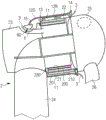
FIG. 1 shows a first embodiment of the cooling mechanism of the present invention;
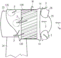
FIG. 2 is a simplified plan view of a portion of the cooling mechanism of FIG. 1;
FIG. 3 shows a simplified side view of a portion of a cooling mechanism in yet another embodiment of the invention;
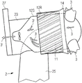
fig. 4 shows a further embodiment of the cooling mechanism 1 of the present invention.
In the drawings, like reference numerals refer to like objects throughout. The objects in the drawings are not necessarily to scale.
Detailed Description
Fig. 1 shows a cooling mechanism 1 of a first embodiment of the invention for a direct drive wind turbine 2 having a generator with an outer rotor 20 directly connected to a hub 25 and wherein the generator is mounted on a tower 24 and connected to a nacelle cover 23 by means of a labyrinth seal 230 between the outer rotor 20 and the nacelle cover 23. When the wind rotates the rotor blades 26 of the wind turbine, the hub 25 and thus the outer rotor 20 also rotate at the same rotational speed. During operation of the generator, the windings 210 of the inner stator 21 become very hot, causing the magnets 200 to also heat up. The magnets 200 are mounted to the outer rotor 20 and separated from the windings 210 by a narrow air gap, which typically comprises only a few millimeters. Their location makes it difficult to cool them using the conventional internal cooling circuit of the wind turbine 2. Here, the cooling mechanism 1 includes shrouds 12R, 12S, the shrouds 12R, 12S being mounted to the outside of the direct drive wind turbine 2 such that the rotating shroud portions 12R effectively enclose the outer rotor 20 and such that the cooling air flow 3 can pass directly over the rotor outer surface 22. The cooling mechanism 1 further includes a plurality of fins 11 mounted to the outer surface of the outer rotor 20 and extending outward so that they function to dissipate heat. Because the magnets 200 are mounted so close to the rotor housing, and because the fins are mounted directly to the exterior of the rotor housing, they are very effective in drawing heat away from the magnets 200. In the exemplary embodiment, the shroud also has a stationary shroud portion 12S that is connected to a rotating shroud portion 12R by means of a labyrinth seal 13. The duct 15 leads into the outlet channel 6 of the internal cooling circuit of the wind turbine 2. In this example, the exhaust fan 60 of the internal cooling circuit actively draws the heated exhaust air from the interior of the generator and discharges it from the outlet channel 6. In this way, heated air 3' from below the rotating shroud portion 12R is also actively drawn away from the outer rotor 20 and expelled through the outlet passage 6. This mechanism ensures that the magnet 200 is cooled very efficiently with a cooling air flow 3 through the outer rotor 20.
FIG. 2 is a simplified plan view of the arrangement of fins 11 on the outer rotor 20 of the wind turbine of FIG. 1. Each fin extends from the front end 20F to the rear end 20R of the outer rotor 20 and is disposed at a fin angle α 11. When the wind turbine is operating at rated power, the fin angle α 11 is determined by the rotational speed ω of the outer rotor 20, and this is generally associated with a certainMean wind speed vw. These vectors ω, vwThe product of v3 may be used to derive an optimal fin angle α 11 that has substantially the same orientation as the air flow that would normally pass through the rotor. The fins 11 are arranged at equal intervals around the outer rotor 20. A cooling mechanism based solely on the cooling effect of the fins 11 may be sufficient to draw heat away from the magnet. However, the cooling air flow 3 (indicated by several arrows between the fins 11) may tend to leave the spaces between the fins 11 before reaching the rear end 20R of the outer rotor 20. Therefore, an embodiment combining an efficient heat dissipation of the fins 11 with the shroud 12 keeping the cooling air flow 3 close to the outer rotor 20 is preferred.
Fig. 3 shows a simplified side view of the shrouds 12R, 12S arranged around the outer rotor 20 of the wind turbine, similar to the arrangement shown in fig. 1. In this embodiment, the shrouds 12R, 12S include a rotating shroud portion 12R that is mounted around the outer rotor 20 such that the outer rotor 20 and the shroud portion 12R rotate as a single unit as shown above in fig. 1. The cooling air flow 3 enters the space between the rotating shroud portion 12R and the outer rotor 20 and passes between the fins 11 (indicated by broken lines). The cooling air flow 3 is promoted into the rotating shroud portion 12R by the intake air guide 14, which intake air guide 14 in this case is an outwardly flared region located on the front side of the rotating shroud portion 12R, which increases the gas collection area. The stationary shroud portion 12S is arranged above the nacelle cover 23 and has a plurality of ducts 15, each of which may lead into a passage of an internal cooling circuit of the wind turbine. An exhaust fan (not shown) can actively draw heated air 3' from the outer rotor 20, thereby promoting a controlled flow of cooling air flow 3 over the outer rotor 20. After passing the outer rotor 20, the air now comprises heated air 3' which is drawn into the channels of the inner cooling circuit. The heated air 3' may also escape from under the fixed shield portion 12S at locations where plumbing is not convenient. In such an area, at the under hood level, in this example, the stationary shroud portion 12S has an outwardly flared portion 120 that promotes the escape of heated air 3'. Since the shroud is connected to a plurality of exhaust gas outlet passages in this example, it may be referred to as a "manifold".
Fig. 4 shows a cooling mechanism 1 according to another embodiment of the present invention. In this case, there is no connection to components of the internal cooling circuit of the wind turbine 2. Instead, heated air 3' is actively drawn from beneath the shrouds 12S, 12R by means of an exhaust fan 60 located at a convenient location on the exterior of the nacelle cover 23. For example, the exhaust fan 60 may be disposed on the side of the nacelle cover 23 and directed rearward. This may be a preferred location if the wind turbine 2 also utilizes a passive cooler 27 located at the rear, since the passive cooler 27 typically extends to a height above the top of the nacelle cover 23, but is not wider than the nacelle cover 23. In this way, the heated air 3' can be discharged along the sides of the cabin cover 23 without obstruction.
Although the present invention has been disclosed in the form of preferred embodiments and variations thereon, it will be understood that: numerous additional modifications and variations could be made thereto without departing from the scope of the invention. For example, in a relatively simple embodiment, the shroud may comprise only a fixed manifold, which is mounted to the nacelle cover and also extends over the rotor. This embodiment may be advantageous for retrofitting an existing wind turbine with additional rotor cooling means, even if the existing rotor is not equipped with external cooling fins as described above. The cooling air flow facilitated by the stationary shroud surrounding the rotor (even if it only partially encloses the rotor) may be sufficient to effectively cool the magnets.
For the sake of simplicity, it should be understood that: the use of "a" or "an" throughout this application does not exclude a plurality, and "comprising" does not exclude other steps or elements.
Claims (12)
1. A cooling mechanism (1) realized for a direct drive wind turbine (2) having an outer rotor (20) carrying a plurality of magnets (200), the cooling mechanism comprising a plurality of outer cooling elements (11, 12R, 12S) arranged around the outside of the outer rotor (20), wherein a cooling element (11, 12R, 12S) is realized to guide a cooling air flow (3) through the outer rotor (20) and to transfer heat from the magnets (200) to the cooling air flow (3), and wherein a cooling element (12R, 12S) comprises a shield (12R, 12S), the shield (12R, 12S) being configured to guide the cooling air flow (3) through an outer surface (22) of the outer rotor (20),
wherein the shroud (12R, 12S) comprises a rotating shroud portion (12R) mounted to an outer rotor (20), and
wherein the shroud (12R, 12S) comprises a stationary shroud portion (12S) mounted to a nacelle shroud (23) of the wind turbine (2).
2. A cooling mechanism according to claim 1, wherein the cooling element (11) comprises fins (11) extending outwardly from a surface (22) of the outer rotor (20).
3. The cooling mechanism according to claim 2, wherein fins (11) extend from a front end (20F) of the outer rotor (20) to a rear end (20R) of the outer rotor (20).
4. The cooling mechanism according to claim 3, wherein the fins (11) are arranged diagonally between a front end (20F) and a rear end (20R) of the outer rotor (20), and wherein a fin angle (a 11) is determined based on a rated power output of the wind turbine (2).
5. The cooling mechanism according to claim 1, wherein the shroud (12R, 12S) is realized to at least partially enclose the outer rotor (20).
6. The cooling mechanism according to claim 1, wherein the rotating shroud portion (12R) is configured to be spaced from the outer rotor (20) by a distance corresponding to a height of the fins (11).
7. The cooling mechanism of claim 1, comprising: a labyrinth seal (13) between the stationary shroud portion (12S) and the rotating shroud portion (12R).
8. The cooling mechanism of claim 1, comprising: an intake guide portion (14) for guiding the cooling air flow (3) below the shrouds (12R, 12S).
9. The cooling mechanism of claim 1, comprising: a plurality of inwardly oriented ducts (15) configured to guide the cooling air flow (3) from below the shrouds (12R, 12S) into an internal cooling circuit of the wind turbine (2).
10. The cooling mechanism of claim 1, comprising: an exhaust fan (60) configured to draw heated air (3') from below the shroud (12R, 12S) along an exterior of a nacelle cover (23) of the wind turbine.
11. A direct drive wind turbine (2) comprising an external rotor (20) carrying a plurality of magnets (200), and a cooling mechanism (1) according to any of claims 1 to 10 for transferring heat from the magnets (200) to an external cooling air flow (3).
12. A method of cooling an outer rotor (20) of a direct drive wind turbine (2), the outer rotor (20) carrying a plurality of magnets (200), the method comprising the steps of:
-arranging a plurality of cooling elements (11, 12R, 12S) around the outside of the outer rotor (20); and
-directing a cooling air flow (3) through the outer rotor (20) to transfer heat from the magnet (200) to the cooling air flow (3),
wherein the cooling element (12R, 12S) comprises a shroud (12R, 12S), the shroud (12R, 12S) being configured to direct the cooling air flow (3) over an outer surface (22) of the outer rotor (20),
wherein the shroud (12R, 12S) comprises a rotating shroud portion (12R) mounted to an outer rotor (20), and
wherein the shroud (12R, 12S) comprises a stationary shroud portion (12S) mounted to a nacelle shroud (23) of the wind turbine (2).
Applications Claiming Priority (2)
| Application Number | Priority Date | Filing Date | Title |
|---|---|---|---|
| EP14153084.0 | 2014-01-29 | ||
| EP14153084.0A EP2902619B1 (en) | 2014-01-29 | 2014-01-29 | Cooling arrangement for a direct drive wind turbine |
Publications (2)
| Publication Number | Publication Date |
|---|---|
| CN104806458A CN104806458A (en) | 2015-07-29 |
| CN104806458B true CN104806458B (en) | 2020-01-07 |
Family
ID=50028843
Family Applications (1)
| Application Number | Title | Priority Date | Filing Date |
|---|---|---|---|
| CN201510045481.2A Active CN104806458B (en) | 2014-01-29 | 2015-01-29 | Cooling mechanism |
Country Status (3)
| Country | Link |
|---|---|
| US (1) | US9410532B2 (en) |
| EP (1) | EP2902619B1 (en) |
| CN (1) | CN104806458B (en) |
Families Citing this family (7)
| Publication number | Priority date | Publication date | Assignee | Title |
|---|---|---|---|---|
| EP3001540B1 (en) * | 2014-09-26 | 2018-03-21 | ALSTOM Renewable Technologies | Direct-drive wind turbines |
| EP3144528B1 (en) | 2015-09-15 | 2018-03-14 | Siemens Aktiengesellschaft | Wind turbine with a brake dust collector |
| WO2019140658A1 (en) * | 2018-01-19 | 2019-07-25 | 深圳市大疆创新科技有限公司 | Heat dissipation structure, heat dissipation method and device, unmanned aerial vehicle and readable storage medium |
| EP3872967A1 (en) * | 2020-02-27 | 2021-09-01 | Siemens Gamesa Renewable Energy A/S | External rotor house of wind power generator with enhanced magnet cooling |
| DE102021107905A1 (en) | 2021-03-29 | 2022-09-29 | Wobben Properties Gmbh | Air cooling device, generator, air guiding device, wind turbine and method for producing a generator and a wind turbine |
| CN116094217A (en) * | 2022-09-30 | 2023-05-09 | 广东肇庆德通有限公司 | Commercial large ceiling fan of outer rotor permanent magnet synchronous motor |
| CN116696666B (en) * | 2023-06-27 | 2024-01-23 | 河南华殊电力工程有限公司 | Overheat emergency braking device of wind driven generator |
Citations (1)
| Publication number | Priority date | Publication date | Assignee | Title |
|---|---|---|---|---|
| CN102447327A (en) * | 2010-10-13 | 2012-05-09 | 西门子公司 | A generator, in particular for a wind turbine |
Family Cites Families (23)
| Publication number | Priority date | Publication date | Assignee | Title |
|---|---|---|---|---|
| DE19636591C2 (en) * | 1996-09-10 | 1999-12-09 | Friedrich Klinger | Synchronous generator for a gearless wind energy converter |
| FR2797921B1 (en) * | 1999-09-01 | 2001-09-28 | Alstom | WIND TURBINE PLATFORM CONSISTING OF THE CARCASS OF AN ELECTRIC GENERATOR |
| NL1013129C2 (en) | 1999-09-24 | 2001-03-27 | Lagerwey Windturbine B V | Windmill. |
| US6483199B2 (en) * | 2000-04-28 | 2002-11-19 | Mitsubishi Denki Kabushiki Kaisha | Wind power generating device |
| ITBZ20040047A1 (en) | 2004-09-20 | 2004-12-20 | High Technology Invest Bv | ELECTRIC GENERATOR / MOTOR, IN PARTICULAR FOR USE IN WIND PLANTS, ROPE OR HYDRAULIC PLANTS. |
| US7345376B2 (en) * | 2004-11-30 | 2008-03-18 | Distributed Energy Systems Corporation | Passively cooled direct drive wind turbine |
| CA2597185A1 (en) * | 2005-02-02 | 2006-08-10 | Magnetic Applications, Inc. | Pulse generator for a controlled rectifier |
| US7427814B2 (en) * | 2006-03-22 | 2008-09-23 | General Electric Company | Wind turbine generators having wind assisted cooling systems and cooling methods |
| IT1391770B1 (en) | 2008-11-13 | 2012-01-27 | Rolic Invest Sarl | WIND GENERATOR FOR THE GENERATION OF ELECTRICITY |
| US9039369B2 (en) * | 2009-01-30 | 2015-05-26 | Vestas Wind Systems A/S | Wind turbine nacelle with cooler top |
| EP2494191B1 (en) * | 2009-10-29 | 2014-05-21 | Mervento Oy | Wind power station |
| IT1398060B1 (en) | 2010-02-04 | 2013-02-07 | Wilic Sarl | PLANT AND METHOD OF COOLING OF AN ELECTRIC GENERATOR OF AN AIR SPREADER, AND AIRCONDITIONER INCLUDING SUCH A COOLING PLANT |
| IT1399511B1 (en) | 2010-04-22 | 2013-04-19 | Wilic Sarl | ELECTRIC GENERATOR FOR A VENTILATOR AND AEROGENER EQUIPPED WITH THIS ELECTRIC GENERATOR |
| US7963743B1 (en) * | 2010-10-16 | 2011-06-21 | Winter Curt B | Wind turbine with improved cooling |
| EP2477311B1 (en) * | 2011-01-18 | 2014-03-05 | Siemens Aktiengesellschaft | Generator, in particular for a wind turbine |
| ITMI20110376A1 (en) | 2011-03-10 | 2012-09-11 | Wilic Sarl | FLUID COOLED AIRBRUSHER |
| ITMI20110377A1 (en) | 2011-03-10 | 2012-09-11 | Wilic Sarl | ROTARY ELECTRIC MACHINE FOR AEROGENERATOR |
| ITMI20110378A1 (en) | 2011-03-10 | 2012-09-11 | Wilic Sarl | ROTARY ELECTRIC MACHINE FOR AEROGENERATOR |
| ITMI20110375A1 (en) * | 2011-03-10 | 2012-09-11 | Wilic Sarl | WIND TURBINE |
| JP2015516528A (en) * | 2012-01-13 | 2015-06-11 | ユーウィンエナジー | Wind turbine cooling system |
| US20130300124A1 (en) * | 2012-05-11 | 2013-11-14 | Clipper Windpower, Inc. | Profiled Air Cap on Direct Drive Wind Turbine Generator |
| CN202749924U (en) * | 2012-08-23 | 2013-02-20 | 浙江家利乐机电有限公司 | External rotor permanent magnet generator |
| DK2806542T3 (en) * | 2013-05-22 | 2016-12-19 | Siemens Ag | Airflow Control Device |
-
2014
- 2014-01-29 EP EP14153084.0A patent/EP2902619B1/en not_active Not-in-force
- 2014-09-24 US US14/494,769 patent/US9410532B2/en not_active Expired - Fee Related
-
2015
- 2015-01-29 CN CN201510045481.2A patent/CN104806458B/en active Active
Patent Citations (1)
| Publication number | Priority date | Publication date | Assignee | Title |
|---|---|---|---|---|
| CN102447327A (en) * | 2010-10-13 | 2012-05-09 | 西门子公司 | A generator, in particular for a wind turbine |
Also Published As
| Publication number | Publication date |
|---|---|
| EP2902619A1 (en) | 2015-08-05 |
| US9410532B2 (en) | 2016-08-09 |
| CN104806458A (en) | 2015-07-29 |
| EP2902619B1 (en) | 2018-01-17 |
| US20150211490A1 (en) | 2015-07-30 |
Similar Documents
| Publication | Publication Date | Title |
|---|---|---|
| CN104806458B (en) | Cooling mechanism | |
| EP2958217B1 (en) | Generator cooling arrangement | |
| US11073136B2 (en) | Cooling arrangement | |
| JP2015528535A (en) | Integrated cooling system for wind turbine nacelle | |
| US11060510B2 (en) | Wind turbine cooling arrangement | |
| EP2802774B1 (en) | Cooling system of a wind turbine | |
| JP2016226277A (en) | Stator comprising integrated radiator | |
| US9768667B2 (en) | Electric motor with outer radiator and two separate cooling circuits | |
| EP3764523B1 (en) | Electric machine with integrated cooling system | |
| US8816547B2 (en) | Electric machine with cooling arrangement | |
| CN109936257B (en) | Electric motor comprising an exchanger and a plurality of cooling circuits | |
| WO2020052467A1 (en) | Stator assembly, motor having same and wind power generator set | |
| EP2950430B1 (en) | Electrical machine system and wind power generating system | |
| JP2022127097A (en) | Power conversion device | |
| EP2493059A1 (en) | A generator, in particular for a wind turbine | |
| US10506735B2 (en) | Heat exchange device in directed flow system | |
| KR101165230B1 (en) | Supercoducting motor | |
| KR20060041572A (en) | Motor cooling system of vehicle | |
| CN103427556A (en) | High-power high-speed electric machine and high-power high-speed draught fan |
Legal Events
| Date | Code | Title | Description |
|---|---|---|---|
| C06 | Publication | ||
| PB01 | Publication | ||
| C10 | Entry into substantive examination | ||
| SE01 | Entry into force of request for substantive examination | ||
| TA01 | Transfer of patent application right |
Effective date of registration: 20190724 Address after: Tango barley Applicant after: Siemens Gamesa Renewable Energy Address before: Munich, Germany Applicant before: Siemens AG |
|
| TA01 | Transfer of patent application right | ||
| GR01 | Patent grant | ||
| GR01 | Patent grant |