EP3709069B1 - Zur seitlichen verschiebung eines bildes fähige anzeigevorrichtung - Google Patents
Zur seitlichen verschiebung eines bildes fähige anzeigevorrichtung Download PDFInfo
- Publication number
- EP3709069B1 EP3709069B1 EP19201064.3A EP19201064A EP3709069B1 EP 3709069 B1 EP3709069 B1 EP 3709069B1 EP 19201064 A EP19201064 A EP 19201064A EP 3709069 B1 EP3709069 B1 EP 3709069B1
- Authority
- EP
- European Patent Office
- Prior art keywords
- image
- optical system
- optical
- optical member
- display apparatus
- Prior art date
- Legal status (The legal status is an assumption and is not a legal conclusion. Google has not performed a legal analysis and makes no representation as to the accuracy of the status listed.)
- Active
Links
Images






Classifications
-
- G—PHYSICS
- G06—COMPUTING OR CALCULATING; COUNTING
- G06T—IMAGE DATA PROCESSING OR GENERATION, IN GENERAL
- G06T3/00—Geometric image transformations in the plane of the image
- G06T3/20—Linear translation of whole images or parts thereof, e.g. panning
-
- G—PHYSICS
- G02—OPTICS
- G02B—OPTICAL ELEMENTS, SYSTEMS OR APPARATUS
- G02B27/00—Optical systems or apparatus not provided for by any of the groups G02B1/00 - G02B26/00, G02B30/00
- G02B27/01—Head-up displays
- G02B27/017—Head mounted
- G02B27/0172—Head mounted characterised by optical features
-
- G—PHYSICS
- G02—OPTICS
- G02B—OPTICAL ELEMENTS, SYSTEMS OR APPARATUS
- G02B27/00—Optical systems or apparatus not provided for by any of the groups G02B1/00 - G02B26/00, G02B30/00
- G02B27/0093—Optical systems or apparatus not provided for by any of the groups G02B1/00 - G02B26/00, G02B30/00 with means for monitoring data relating to the user, e.g. head-tracking, eye-tracking
-
- G—PHYSICS
- G02—OPTICS
- G02B—OPTICAL ELEMENTS, SYSTEMS OR APPARATUS
- G02B27/00—Optical systems or apparatus not provided for by any of the groups G02B1/00 - G02B26/00, G02B30/00
- G02B27/0075—Optical systems or apparatus not provided for by any of the groups G02B1/00 - G02B26/00, G02B30/00 with means for altering, e.g. increasing, the depth of field or depth of focus
-
- G—PHYSICS
- G02—OPTICS
- G02B—OPTICAL ELEMENTS, SYSTEMS OR APPARATUS
- G02B27/00—Optical systems or apparatus not provided for by any of the groups G02B1/00 - G02B26/00, G02B30/00
- G02B27/0081—Optical systems or apparatus not provided for by any of the groups G02B1/00 - G02B26/00, G02B30/00 with means for altering, e.g. enlarging, the entrance or exit pupil
-
- G—PHYSICS
- G02—OPTICS
- G02B—OPTICAL ELEMENTS, SYSTEMS OR APPARATUS
- G02B27/00—Optical systems or apparatus not provided for by any of the groups G02B1/00 - G02B26/00, G02B30/00
- G02B27/01—Head-up displays
- G02B27/0179—Display position adjusting means not related to the information to be displayed
-
- G—PHYSICS
- G02—OPTICS
- G02B—OPTICAL ELEMENTS, SYSTEMS OR APPARATUS
- G02B27/00—Optical systems or apparatus not provided for by any of the groups G02B1/00 - G02B26/00, G02B30/00
- G02B27/10—Beam splitting or combining systems
-
- G—PHYSICS
- G02—OPTICS
- G02B—OPTICAL ELEMENTS, SYSTEMS OR APPARATUS
- G02B27/00—Optical systems or apparatus not provided for by any of the groups G02B1/00 - G02B26/00, G02B30/00
- G02B27/10—Beam splitting or combining systems
- G02B27/12—Beam splitting or combining systems operating by refraction only
- G02B27/126—The splitting element being a prism or prismatic array, including systems based on total internal reflection
-
- G—PHYSICS
- G02—OPTICS
- G02B—OPTICAL ELEMENTS, SYSTEMS OR APPARATUS
- G02B27/00—Optical systems or apparatus not provided for by any of the groups G02B1/00 - G02B26/00, G02B30/00
- G02B27/64—Imaging systems using optical elements for stabilisation of the lateral and angular position of the image
-
- G—PHYSICS
- G02—OPTICS
- G02F—OPTICAL DEVICES OR ARRANGEMENTS FOR THE CONTROL OF LIGHT BY MODIFICATION OF THE OPTICAL PROPERTIES OF THE MEDIA OF THE ELEMENTS INVOLVED THEREIN; NON-LINEAR OPTICS; FREQUENCY-CHANGING OF LIGHT; OPTICAL LOGIC ELEMENTS; OPTICAL ANALOGUE/DIGITAL CONVERTERS
- G02F1/00—Devices or arrangements for the control of the intensity, colour, phase, polarisation or direction of light arriving from an independent light source, e.g. switching, gating or modulating; Non-linear optics
- G02F1/29—Devices or arrangements for the control of the intensity, colour, phase, polarisation or direction of light arriving from an independent light source, e.g. switching, gating or modulating; Non-linear optics for the control of the position or the direction of light beams, i.e. deflection
-
- G—PHYSICS
- G06—COMPUTING OR CALCULATING; COUNTING
- G06F—ELECTRIC DIGITAL DATA PROCESSING
- G06F3/00—Input arrangements for transferring data to be processed into a form capable of being handled by the computer; Output arrangements for transferring data from processing unit to output unit, e.g. interface arrangements
- G06F3/01—Input arrangements or combined input and output arrangements for interaction between user and computer
- G06F3/011—Arrangements for interaction with the human body, e.g. for user immersion in virtual reality
-
- G—PHYSICS
- G06—COMPUTING OR CALCULATING; COUNTING
- G06F—ELECTRIC DIGITAL DATA PROCESSING
- G06F3/00—Input arrangements for transferring data to be processed into a form capable of being handled by the computer; Output arrangements for transferring data from processing unit to output unit, e.g. interface arrangements
- G06F3/01—Input arrangements or combined input and output arrangements for interaction between user and computer
- G06F3/011—Arrangements for interaction with the human body, e.g. for user immersion in virtual reality
- G06F3/013—Eye tracking input arrangements
-
- G—PHYSICS
- G06—COMPUTING OR CALCULATING; COUNTING
- G06T—IMAGE DATA PROCESSING OR GENERATION, IN GENERAL
- G06T19/00—Manipulating three-dimensional [3D] models or images for computer graphics
- G06T19/006—Mixed reality
-
- G—PHYSICS
- G06—COMPUTING OR CALCULATING; COUNTING
- G06T—IMAGE DATA PROCESSING OR GENERATION, IN GENERAL
- G06T5/00—Image enhancement or restoration
- G06T5/73—Deblurring; Sharpening
-
- G—PHYSICS
- G06—COMPUTING OR CALCULATING; COUNTING
- G06T—IMAGE DATA PROCESSING OR GENERATION, IN GENERAL
- G06T7/00—Image analysis
- G06T7/70—Determining position or orientation of objects or cameras
-
- G—PHYSICS
- G06—COMPUTING OR CALCULATING; COUNTING
- G06V—IMAGE OR VIDEO RECOGNITION OR UNDERSTANDING
- G06V40/00—Recognition of biometric, human-related or animal-related patterns in image or video data
- G06V40/10—Human or animal bodies, e.g. vehicle occupants or pedestrians; Body parts, e.g. hands
- G06V40/18—Eye characteristics, e.g. of the iris
- G06V40/19—Sensors therefor
-
- G—PHYSICS
- G02—OPTICS
- G02B—OPTICAL ELEMENTS, SYSTEMS OR APPARATUS
- G02B27/00—Optical systems or apparatus not provided for by any of the groups G02B1/00 - G02B26/00, G02B30/00
- G02B27/01—Head-up displays
- G02B27/017—Head mounted
- G02B2027/0178—Eyeglass type
-
- G—PHYSICS
- G02—OPTICS
- G02B—OPTICAL ELEMENTS, SYSTEMS OR APPARATUS
- G02B27/00—Optical systems or apparatus not provided for by any of the groups G02B1/00 - G02B26/00, G02B30/00
- G02B27/01—Head-up displays
- G02B27/0179—Display position adjusting means not related to the information to be displayed
- G02B2027/0187—Display position adjusting means not related to the information to be displayed slaved to motion of at least a part of the body of the user, e.g. head, eye
-
- G—PHYSICS
- G02—OPTICS
- G02F—OPTICAL DEVICES OR ARRANGEMENTS FOR THE CONTROL OF LIGHT BY MODIFICATION OF THE OPTICAL PROPERTIES OF THE MEDIA OF THE ELEMENTS INVOLVED THEREIN; NON-LINEAR OPTICS; FREQUENCY-CHANGING OF LIGHT; OPTICAL LOGIC ELEMENTS; OPTICAL ANALOGUE/DIGITAL CONVERTERS
- G02F1/00—Devices or arrangements for the control of the intensity, colour, phase, polarisation or direction of light arriving from an independent light source, e.g. switching, gating or modulating; Non-linear optics
- G02F1/29—Devices or arrangements for the control of the intensity, colour, phase, polarisation or direction of light arriving from an independent light source, e.g. switching, gating or modulating; Non-linear optics for the control of the position or the direction of light beams, i.e. deflection
- G02F1/294—Variable focal length devices
Definitions
- Example embodiments of the present disclosure relate to a display apparatus capable of laterally shifting an image, and more particularly, to a display apparatus that may shift an image according to a position of a pupil of an observer, thereby substantially expanding a viewing window.
- AR unlike VR assuming a complete virtual world, is a display technology for showing a virtual object or information in an overlapping or combined manner in a real-world environment, further enhancing the effect of reality. While VR is only applicable to virtual experiences, such as in the field of game, AR is more widely applicable to various real environments. In particular, AR has attracted much attention as a next-generation display technology suitable for a ubiquitous environment or an Internet of things (IoT) environment. Such AR may be an example of MR in that it shows the real world and additional information of the virtual world in a mixed manner.
- IoT Internet of things
- a viewing window In a VR, AR, or MR display apparatus, various techniques for expanding a viewing window have been proposed. For example, foveated rendering may be implemented or image depth may be adjusted, according to a position of a pupil of an observer. Alternatively, a position of an image to be displayed may be controlled using a rotating mirror or a shifting mirror.
- JP 2009192559A discloses an image display apparatus including a light source part, an image light forming part for forming image light, by converting light emitted from the light source part into the image light expressing an image display apparatus to an observer, and an emission pupil control part for controlling a position of the emission pupil of the image display apparatus.
- the emission pupil control part includes a liquid crystal optical device, and an emission pupil control means for controlling the position of the emission pupil, by controlling the liquid crystal optical device.
- the image light forming part corrects a conversion characteristic of converting the emission light from the light source part by the image light forming part, based on a controlled variable of the liquid crystal optical device, to cancel a change, of a geometric characteristic of the image recognized by the observer, caused by control of the liquid crystal optical device.
- One or more example embodiments provide a display apparatus capable of laterally shifting an image, and more particularly, to a display apparatus that may shift an image according to a position of a pupil of an observer, thereby substantially expanding a viewing window. According to an aspect of an example embodiment, there is provided a display apparatus including features defined in the appended independent apparatus claim BRIEF DESCRIPTION OF THE
- example embodiments may have different forms and should not be construed as being limited to the descriptions set forth herein. Accordingly, the example embodiments are merely described below, by referring to the figures, to explain aspects.
- the term “and/or” includes any and all combinations of one or more of the associated listed items. Expressions such as “at least one of,” when preceding a list of elements, modify the entire list of elements and do not modify the individual elements of the list.
- the expression, "at least one of a, b, and c,” should be understood as including only a, only b, only c, both a and b, both a and c, both b and c, or all of a, b, and c.
- FIG. 1 schematically illustrates a structure of a display apparatus 100 according to an example embodiment.
- the display apparatus 100 includes an image forming optical system 110 configured to form an image to be displayed, an image shifting optical system 120 configured to shift an image in a direction perpendicular to an optical axis OX, and an eyepiece optical system 130 configured to provide an image to a pupil of an observer.
- the display apparatus 100 further includes an eye tracker 150 configured to track a position of a pupil of an observer and a controller 140 configured to control a position of the image shifting optical system 120 in response to a change of the position of the pupil of the observer, provided from the eye tracker 150.
- the eye tracker 150 may obtain an image of the observer through a camera, etc., detect the pupil of the observer from the image, and analyze the position of the pupil of the observer.
- the eye tracker 150 may track the change of the position of the pupil of the observer and provide a result of the tracking to the controller 140.
- the image forming optical system 110 may include an illuminating device 111 that provides illumination light, a spatial optical modulator 114 that forms an image by reflecting and modulating the illumination light, a beam splitter 112 configured to deliver the illumination light to the spatial optical modulator 114 and to deliver the image formed by the spatial optical modulator 114 to the image shifting optical system 120, and an objective lens 113 disposed between the spatial optical modulator 114 and the beam splitter 112.
- the objective lens 113 is illustrated as one lens element in FIG. 1 , the objective lens 113 may include a plurality of lens elements configured to correct aberration and distortion of the image.
- the illuminating device 111 may include, for example, an array of a plurality of light-emitting diodes (LEDs) that emit red light, green light, and blue light, but example embodiments are not limited thereto.
- the illumination light emitted from the illuminating device 111 after being reflected by the beam splitter 112, may become parallel light by passing through the objective lens 113, and may be incident on the spatial optical modulator 114.
- the objective lens 113 may serve as a collimating lens that collimates the illumination light delivered from the illuminating device 111 to the spatial optical modulator 114.
- the spatial optical modulator 114 may form an image by modulating the incident light based on an image signal provided from a signal processor.
- the spatial optical modulator 114 may include, for example, a liquid crystal on silicon (LCoS) panel, a digital light projection (DLP) panel, or a digital micromirror device (DMD) panel.
- the spatial optical modulator 114 may form the image by changing a reflectivity according to a position of the incident light on a surface of the spatial optical modulator 114.
- the image formed by reflection of the illumination light through the spatial optical modulator 114 may pass through the objective lens 113.
- the objective lens 113 may focus the image formed by the spatial optical modulator 114 to a first pupil P1 between the image forming optical system 110 and the image shifting optical system 120.
- the image shifting optical system 120 is disposed on a light path between the image forming optical system 110 and the eyepiece optical system 130, and relay the image to the eyepiece optical system 130 and at the same time, shift the image in a direction perpendicular to the optical axis OX.
- the image shifting optical system 120 may shift the image under control of the controller 140 to more accurately provide the image to the pupil of the observer in response to the change of the position of the pupil of the observer provided from the eye tracker 150.
- the image shifting optical system 120 includes a first optical member 121, a second optical member 122, and an actuator 123 that moves the image shifting optical system 120 in the direction perpendicular to the optical axis OX under control of the controller 140.
- the actuator 123 is configured to move the first optical member 121 and the second optical member 122 perpendicularly to the optical axis OX at the same time.
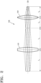
- FIG. 2 illustrates in detail an optical structure of the image shifting optical system 120 of the display apparatus 100 illustrated in FIG. 1 .
- the image shifting optical system 120 includes the first optical member 121 and the second optical member 122 that are sequentially disposed along the optical axis OX.
- the first optical member 121 may be a convex lens having a first focal length f A
- the second optical member 122 may be a convex lens having a second focal length f B .
- each of the first optical member 121 and the second optical member 122 is illustrated in FIG. 1 as a single lens
- each of the first optical member 121 and the second optical member 122 may include a plurality of lens elements, respectively.
- each of the first optical member 121 and the second optical member 122 may include at least one lens group having a positive refractive power, each of which includes at least two lens elements.
- the first optical member 121 and the second optical member 122 may relay the image focused on the first pupil P1 between the image forming optical system 110 and the image shifting optical system 120 and focus the image to a second pupil P2 between the image shifting optical system 120 and the eyepiece optical system 130.
- the first optical member 121 and the second optical member 122 are spaced apart from each other by a sum of the first focal length f A and the second focal length f B . That is, a distance between the first optical member 121 and the second optical member 122 on the optical axis OX is equal to the sum f A + f B of the first focal length f A and the second focal length f B .
- the distance between the first optical member 121 and the second optical member 122 may be measured with respect to a central point of the first optical member 121 and a central point of the second optical member 122 on the optical axis OX.
- the first optical member 121 may be disposed to be spaced apart by the first focal length f A along the optical axis OX toward an image side, from a plane perpendicular to the optical axis OX on which the first pupil P1 to which the image is focused is located between the image forming optical system 110 and the first optical member 121.
- the second optical member 122 may be disposed to be spaced apart by the second focal length f B along the optical axis OX, toward an object side from a plane perpendicular to the optical axis OX on which the second pupil P2 to which the image is focused is located between the second optical member 122 and the eyepiece optical system 130.
- the image shifting optical system 120 may satisfy an afocal condition and a telecentric condition, thus delivering the image on the first pupil P1 to the second pupil P2.
- the image shifting optical system 120 may shift the image of the first pupil P1 on the optical axis OX, in the direction perpendicular to the optical axis OX along the plane perpendicular to the optical axis OX on which the second pupil P2 is located.
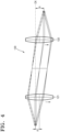
- FIGS. 3 and 4 illustrate operations of the image shifting optical system illustrated in FIG. 2 .
- the first optical member 121 and the second optical member 122 of the image shifting optical system 120 move up by a distance ⁇ in the direction perpendicular to the optical axis OX
- the image is shifted up by a distance ⁇ in the direction perpendicular to the optical axis OX on the plane where the second pupil P2 is located.
- the distance ⁇ by which the image is shifted may be expressed by Equation 1.
- ⁇ ⁇ ⁇ 1 M A ⁇ 1
- M A indicates a magnification of the image shifting optical system 120.
- the magnification M A of the image shifting optical system 120 may be expressed by Equation 2.
- M A ⁇ f A f b
- the eyepiece optical system 130 is configured to deliver the image on the second pupil P2 to a pupil of an eye E of the observer.
- the eyepiece optical system 130 may include at least two lens elements 131 and 132 configured to focus the image focused on the second pupil P2 to the exit pupil. While the eyepiece optical system 130 is illustrated in FIG. 1 as including the two lens elements 131 and 132, the eyepiece optical system 130 may include more lens elements to compensate aberration and distortion of the image.
- the image on the second pupil P2 is enlarged or reduced with a magnification M P by the eyepiece optical system 130.
- the observer may see an enlarged or reduced imaginary image located on an image plane IP.
- the position of the exit pupil of the eyepiece optical system 130 is opposite to the position of the second pupil P2.
- the exit pupil of the eyepiece optical system 130 is located on the optical axis OX.
- the exit pupil of the eyepiece optical system 130 is formed under the optical axis OX
- the exit pupil of the eyepiece optical system 130 is formed above the optical axis OX.
- FIG. 5 illustrates movement of the exit pupil of the eyepiece optical system 130 with respect to movement of the image shifting optical system 120 in the display apparatus 100 illustrated in FIG. 1 .
- the image shifting optical system 120 moves down with respect to the optical axis OX
- the second pupil P2 also moves down with respect to the optical axis OX.
- the exit pupil of the eyepiece optical system 130 moves up with respect to the optical axis OX.
- the controller 140 locates the image shifting optical system 120 on the optical axis OX.
- the controller 140 may move the image shifting optical system 120 down with respect to the optical axis OX for a position of the exit pupil of the eyepiece optical system 130 to coincide with a position of the pupil of the eye E of the observer.
- the controller 140 may move the image shifting optical system 120 up with respect to the optical axis OX for the position of the exit pupil of the eyepiece optical system 130 to coincide with the position of the pupil of the eye E of the observer.
- FIG. 6 is an enlarged view of shifting of an image with respect to change of a position of the pupil of the eye E of the observer according to an example embodiment.
- the controller 140 may move the exit pupil of the eyepiece optical system 130 up by a the distance ⁇ P with respect to the optical axis OX to more accurately provide an image to the observer.
- a relationship between a movement distance ⁇ P of the exit pupil of the eyepiece optical system 130 and a movement distance ⁇ of the second pupil P2 by the image shifting optical system 120 may be expressed as in Equation 3.
- ⁇ P M P ⁇ ⁇
- Equation 3 M P indicates a magnification of the eyepiece optical system 130.
- the image shifting optical system 120 uses the two optical members 121 and 122, which may contribute to miniaturization of the display apparatus 100. Moreover, based on the image being shifted in the direction perpendicular to the optical axis OX without being shifted in a direction parallel with the optical axis OX, a more accurate image may be provided to the pupil of the observer. In addition, even when the image is shifted, the image is not inclined. Thus, a more accurate image that is not distorted may be provided to the observer.
- the image shifting optical system 120 is interposed on an optical path between the image forming optical system 110 and the eyepiece optical system 130, increasing the length of the entire optical system of the display apparatus 100 by 2 ⁇ (f A + f B ).
- the first focal length f A of the first optical member 121 and the second focal length f B of the second optical member 122 of the image shifting optical system 120 may be shortened.
- an effective focal length of the entire optical system of the display apparatus 100 may be determined by a size h and a viewing angle ⁇ of the spatial optical modulator 114 as in Equation 4.
- Effective focal length of system h tan ⁇
- An effective focal length of the objective lens 113 of the image forming optical system 110 may be defined by Equation 5. h tan ⁇ ⁇ M A M P
- the second pupil P2 may move more even when the image shifting optical system 120 moves less.
- the first focal length f A of the first optical member 121 and the second focal length f B of the second optical member 122 may be equal to each other.
- example embodiments are not limited thereto.
- the first focal length f A of the first optical member 121 and the second focal length f B of the second optical member 122 may be set differently, based on the size and performance of the entire optical system of the display apparatus 100.
- FIGS. 7, 8 , and 9 illustrate various example electronic devices to which the above-described display apparatus 100 is applicable.
- the display apparatus 100 may be included in a wearable device.
- the display apparatus 100 may be applied to the wearable device.
- the display apparatus 100 may be applied to a head mounted display (HMD).
- the display apparatus 100 may be applied to a glasses-type display, a goggle-type display, etc.
- Wearable electronic devices illustrated in FIGS. 7, 8 , and 9 may operate in association with a smart phone.
- the display apparatus 100 may be a head-mounted type, glasses-type, or goggle-type VR display apparatus, AR display apparatus, or MR display apparatus capable of providing VR or a virtual image together with an external real image.
- the display apparatus 100 may be included in a smart phone that may be used as a multi-image display apparatus.
- the display apparatus 100 may be applied in a small-size electronic device, such as a mobile electronic device, as well as the wearable device illustrated in FIGS. 7, 8 , and 9 .
- An application field of the display apparatus 100 may be changed variously.
- the display apparatus 100 may be applied to implement VR, AR, or MR, and to other fields.
- the display apparatus 100 may be applied to a small-size television (TV), a small-size monitor, etc., the user may wear.
- TV small-size television
- monitor a small-size monitor
- FIG. 10 is a perspective view schematically illustrating a structure of a display apparatus according to an example embodiment.
- a display apparatus 200 includes an image forming optical system 210, an image shifting optical system 220, and an eyepiece optical system 230.
- the example embodiment in FIG. 10 further includes the controller 140 and the eye tracker 150 illustrated in FIG. 1 .
- an illuminating device 211, a first beam splitter 212, an objective lens 213, and a spatial optical modulator 214 may be the same as those described with reference to FIG. 1 .
- the image forming optical system 210 may further include a folding mirror 216 that reflects an image focused by the objective lens 213 to bend a travel path of the image.
- the folding mirror 216 may bend an optical path, for example, by about 90 degrees.
- example embodiments are not limited thereto, and a bending angle of the optical path may change with a shape of an inner space of the wearable device illustrated in FIGS. 7, 8 , and 9 .
- the image forming optical system 210 may be positioned at a tip portion of an ear grip of the wearable device, and the image reflected by the folding mirror 216 may move toward a glasses screen along a temple of the wearable device.
- the image shifting optical system 220 includes a first optical member 221 and a second optical member 222. Structures and operations of the first optical member 221 and the second optical member 222 of the image shifting optical system 220 may be the same as those described above.
- the first optical member 221 and the second optical member 222 may be disposed, for example, inside the temple of the wearable device.
- the eyepiece optical system 230 may include a second beam splitter 231, a first mirror 232, a third beam splitter 233, and a second mirror 234, which are disposed sequentially along the optical path.
- the second beam splitter 231 may be disposed on the same layer as the image forming optical system 210 and the image shifting optical system 220.
- the second beam splitter 231 may be disposed in a position adjacent to the glasses screen inside the temple of the wearable device.
- the first mirror 232 may be disposed on the second beam splitter 231.
- the third beam splitter 233 and the second mirror 234 may be disposed under the beam splitter 231.
- the third beam splitter 233 and the second mirror 234 may be disposed in the glasses screen of the wearable device.
- the first mirror 232 may be a simple plane mirror. Instead, the first mirror 232 may be a concave mirror that is configured to operate optically equivalent to a convex lens.
- the second mirror 234 may be a concave mirror for focusing an image on the exit pupil.
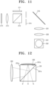
- FIG. 11 is a plan view illustrating arrangement of components disposed on the same layer among components of the display apparatus 200 illustrated in FIG. 10 .
- the illuminating device 211, the first beam splitter 212, the objective lens 213, the spatial optical modulator 214, the folding mirror 216, the first optical member 221, the second optical member 222, and the second beam splitter 231 may be disposed on the same layer.
- the image formed in the image forming optical system 210 is reflected by the folding mirror 216, the image may travel in a horizontal direction as a whole until the image is incident on the second beam splitter 231 by passing through the first optical member 221 and the second optical member 222.
- the image forming optical system 210 may further include a spatial filter 215 that removes light other than the image focused by the objective lens 213. While the spatial filter 215 is illustrated in FIG. 11 as being disposed between the first beam splitter 212 and the folding mirror 216, the spatial filter 215 may be disposed anywhere on the optical path between the first beam splitter 212 and the second beam splitter 231.
- FIG. 12 is a vertical cross-sectional view illustrating a travel path of light incident on the eyepiece optical system 230 in FIGS. 10 and 11 .
- FIG. 12 illustrates the eyepiece optical system 230 viewed from a direction A illustrated in FIG. 10 .
- the second beam splitter 231 may include a first surface 231a disposed to face the image shifting optical system 220, a second surface 231b adjacent to the first surface 231a, and an inclined surface 231c disposed at an angle with respect to the first surface 231a and the second surface 231b.
- the first mirror 232 may be disposed on the second surface 231b of the second beam splitter 231.
- the first mirror 232 reflects the image toward the inclined surface 231c.
- the image incident on the second surface 231b is reflected by the first mirror 232 and then passes through the inclined surface 231c.
- the inclined surface 231c may be a half mirror.
- the inclined surface 231c may reflect 50% of incident light and transmit the remaining 50% of the incident light, but example embodiments are not limited thereto.
- the inclined surface 231c may reflect light coming in a direction from the first surface 231a and transmit light coming in a direction from the second surface 231b.
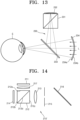
- FIG. 13 is a vertical cross-sectional view illustrating a structure of the eyepiece optical system 230 according to an example embodiment.
- FIG. 13 illustrates the eyepiece optical system 230 viewed from a direction B perpendicular to the direction A in FIG. 10 .
- an image reflected by the first mirror 232 may be incident on the third beam splitter 233.
- the third beam splitter 233 may reflect the image to the second mirror 234.
- the second mirror 234 may be a concave mirror configured to focus the image to the pupil of the observer.
- the first mirror 232 and the second mirror 234 may focus the image to the pupil of the observer together.
- the third beam splitter 233 may be a half mirror.
- the third beam splitter 233 may reflect 50% of incident light and transmit the remaining 50% of the incident light, but example embodiments are not limited thereto.
- the third beam splitter 233 may be configured to reflect light coming in a direction from the first mirror 232 and to transmit light coming in a direction from the second mirror 234.
- the second mirror 234 may be configured to transmit light L coming from outside.
- the second mirror 234 may include a concave first surface 234a and a convex second surface 234b that is disposed opposite the first surface 234a.
- the first surface 234a may be configured to reflect incident light
- the second surface 234b may be configured to transmit the incident light.
- the first surface 234a may focus the image coming from the first mirror 232 while reflecting the image, and the second surface 234b may transmit the light L coming from outside without refraction.
- the observer may then see a virtual image formed by the spatial optical modulator 214, together with view of the outside.
- FIG. 14 is a plan view illustrating a structure of an image forming optical system according to an example embodiment.
- an image forming optical system 210' may include the illuminating device 211, a collimating lens 217 that collimates illumination light emitted from the illuminating device 211 into parallel light, the first beam splitter 212, the objective lens 213, the spatial optical modulator 214, the spatial filter 215, and the folding mirror 216.
- the collimating lens 217 may be disposed to face a first surface 212a of the first beam splitter 212. After the illumination light is incident on the first surface 212a of the first beam splitter 212, the illumination light may be reflected by an inclined surface 212d of the first beam splitter 212 and may be incident on a second surface 212b of the first beam splitter 212. On the second surface 212b of the first beam splitter 212, the spatial optical modulator 214 may be disposed. Although the spatial optical modulator 214 is illustrated in FIG. 14 as being spaced apart from the second surface 212b, the spatial optical modulator 214 may be disposed in contact with the second surface 212b without a gap therebetween.
- the image reflected by the spatial optical modulator 214 may pass through the inclined surface 212d, and then pass through a third surface 212c of the first beam splitter 212.
- the objective lens 213 may be disposed to face the third surface 212c that is opposite the second surface 212b of the first beam splitter 212.
- the image passing through the third surface 212c of the first beam splitter 212 may be focused by the objective lens 213.
- FIG. 15 is a plan view illustrating a structure of an image forming optical system according to an example embodiment. Referring to FIG.
- an image forming optical system 310 may include an illuminating device 311 that provides illumination light, a collimating lens 317 that collimates the illumination light emitted from the illuminating device 311 into parallel light, a spatial optical modulator 314 that forms an image by transmitting and modulating the illumination light, an objective lens 313 that focuses the image formed by the spatial optical modulator 314 to the first pupil P1, and a spatial filter 315 that removes light other than the image focused by the objective lens 313.
- the spatial optical modulator 314 of the transmissive type may use, for example, a semiconductor modulator based on a compound semiconductor such as gallium arsenide (GaAs), or a liquid crystal device (LCD).
- FIG. 16 is a cross-sectional view illustrating a structure of an eyepiece optical system according to an example embodiment.
- an eyepiece optical system 230' may include the second beam splitter 231, the first mirror 232, the third beam splitter 233, and the second mirror 234, which are disposed sequentially along the optical path.
- the second mirror 234 may be disposed to face the first mirror 232 with the third beam splitter 233 therebetween.
- the third beam splitter 233 may include a first surface 233a facing the first surface 232 and a second surface 233b facing the second mirror 234, in which the first surface 233a and the second surface 233b are disposed on opposite sides.
- the third beam splitter 233 may be configured to transmit light incident on the first surface 233a and to reflect light incident on the second surface 233b. An image reflected by the first mirror 232 may then arrive at the second mirror 234 by passing through the first surface 233a of the third beam splitter 233. An image reflected by the second mirror 234 may be focused on the pupil of the observer by being reflected by the second surface 233b of the third beam splitter 233.
- the third beam splitter 233 may be disposed such that the first surface 233a faces the outside. The third beam splitter 233 may then transmit the light L coming from outside without refraction. Thus, the observer may then see a virtual image formed by the spatial optical modulator 214, together with view of the outside.
- the first optical member 121 and the second optical member 122 of the image shifting optical system 120 and the first optical member 221 and the second optical member 222 of the image shifting optical system 220 include convex lenses.
- a concave mirror that is configured to operate optically equivalent to a convex lens may also be used in place of the convex lens.
- FIGS. 17 , 18 , 19 , and 20 illustrate a structure of an image shifting optical system according to various example embodiments.
- an image shifting optical system 320 may include a first optical member 321 including a convex lens, a second optical member 322 including a concave lens, and a beam splitter 323 that may transmit light coming from the first optical member 321 and reflect light coming from the second optical member 322.
- the second optical member 322 may be disposed to face the first optical member 321 with the beam splitter 323 therebetween. That is, the first optical member 321 and the second optical member 322 may be disposed to face opposite surfaces of the beam splitter 323, respectively.
- the image may pass through the beam splitter 323 via the first optical member 321.
- the image may be reflected by the second optical member 322, and may be focused on the second pupil P2 by being reflected by the beam splitter 323.
- an image shifting optical system 320' may include the first optical member 321 including a convex lens, the second optical member 322 including a concave lens, and a beam splitter 323' that may reflect light coming from the first optical member 321 and transmit light coming from the second optical member 322.
- the first optical member 321 and the second optical member 322 may be disposed to face two adjacent surfaces of the beam splitter 323'.
- the image may be reflected by the beam splitter 323' via the first optical member 321.
- the image may be reflected by the second optical member 322, and may be focused on the second pupil P2 by passing through the beam splitter 323'.
- an image shifting optical system 420 may include a first optical member 421 including a concave mirror, a second optical member 422 including a convex mirror, and a beam splitter 423 that may reflect light coming from an image forming optical system and transmit light coming from the first optical member 421 toward the second optical member 422.
- the second optical member 422 may be disposed to face the first optical member 421 with the beam splitter 423 therebetween. That is, the first optical member 421 and the second optical member 422 may be disposed to face opposite surfaces of the beam splitter 423, respectively.
- the image focused on the first pupil P1 by the image forming optical system may be reflected by the beam splitter 423 and then reflected by the first optical member 421. The image may then be focused on the second pupil P2 by the second optical member 422 by passing through the beam splitter 423.
- the beam splitter 423 may be configured to transmit light coming from the image forming optical system and reflect light coming from the first optical member 421 toward the second optical member 422.
- the first optical member 421 and the second optical member 422 may be disposed to face two adjacent surfaces of the beam splitter 423.
- a travel path of the image between the first pupil P1 and the second pupil P2 is bent by about 90 degrees.
- the image shifting optical systems 320, 320', and 420 illustrated in FIGS. 17 , 18, and 19 are used, the image forming optical system 210 may not include the folding mirror 216.
- both a first optical member 521 and a second optical member 522 of an image shifting optical system 520 may be concave mirrors.
- the image shifting optical system 520 may include a first optical member 521 including a concave mirror, a second optical member 522 including a concave mirror, a first beam splitter 523 that may reflect light coming from the image forming optical system and transmit light coming from the first optical member 521 toward the second optical member 522, and a second beam splitter 524 that may transmit light coming from the first optical member 521 and reflect light coming from the second optical member 522.
- the image focused on the first pupil P1 by the image forming optical system may be incident on the first optical member 521 by being reflected by the first beam splitter 523.
- the image may be reflected by the first optical member 521 and then may be incident on the second optical member 522 by passing through the first beam splitter 523 and the second beam splitter 524.
- the image may be reflected by the second optical member 522, and may be focused on the second pupil P2 by being reflected by the second beam splitter 524.
Landscapes
- Physics & Mathematics (AREA)
- General Physics & Mathematics (AREA)
- Engineering & Computer Science (AREA)
- Optics & Photonics (AREA)
- Theoretical Computer Science (AREA)
- General Engineering & Computer Science (AREA)
- Human Computer Interaction (AREA)
- Nonlinear Science (AREA)
- Computer Vision & Pattern Recognition (AREA)
- Computer Graphics (AREA)
- Computer Hardware Design (AREA)
- Software Systems (AREA)
- Health & Medical Sciences (AREA)
- General Health & Medical Sciences (AREA)
- Ophthalmology & Optometry (AREA)
- Multimedia (AREA)
- Lenses (AREA)
Claims (14)
- Anzeigevorrichtung (100, 200), die Folgendes umfasst:ein optisches Bilderzeugungssystem (110), das so ausgelegt ist, dass es ein anzuzeigendes Bild erzeugt;ein optisches Okularsystem (130), das so ausgelegt ist, dass es das durch das optische Bilderzeugungssystem (110) erzeugte Bild an eine Pupille (E) eines Betrachters bereitstellt; undein optisches Bildverschiebungssystem (120, 320), das auf einem optischen Pfad zwischen dem optischen Bilderzeugungssystem (110) und dem optischen Okularsystem (130) angeordnet ist, wobei das optische Bildverschiebungssystem (120, 320) so ausgelegt ist, dass es das durch das optische Bilderzeugungssystem (110) erzeugte Bild in einer Richtung senkrecht zu einer optischen Achse (OX) verschiebt.wobei das optische Bildverschiebungssystem (120, 320) ein erstes optisches Element (121, 321) mit einer ersten Brennweite (fA) und ein zweites optisches Element (122, 322) mit einer zweiten Brennweite (fB) umfasst, und wobei ein Abstand zwischen dem ersten optischen Element und dem zweiten optischen Element entlang der optischen Achse (OX) gleich einer Summe der ersten Brennweite und der zweiten Brennweite ist,DADURCH GEKENNZEICHNET, DASSdie Anzeigevorrichtung ferner Folgendes umfasst:einen Augentracker (150), der so ausgelegt ist, dass er eine Position der Pupille (E) des Betrachters verfolgt;eine Steuerung (140), die so ausgelegt ist, dass sie eine Position des optischen Bildverschiebungssystems (120, 320) basierend auf einer von dem Augentracker (150) bereitgestellten Änderung der Position der Pupille (E) des Betrachters steuert; undeinen Aktuator, der so ausgelegt ist, dass er das optische Bildverschiebungssystem (120, 320) basierend auf einer Steuerung durch die Steuerung (140) in der Richtung senkrecht zu der optischen Achse (OX) bewegt.
- Anzeigevorrichtung nach Anspruch 1, wobei das erste optische Element (121, 321) um die erste Brennweite entlang der optischen Achse (OX) in Richtung einer Bildseite von einer ersten Pupille (P1), auf die das Bild fokussiert wird, zwischen dem optischen Bilderzeugungssystem (110) und dem ersten optischen Element (121, 321) beabstandet ist, wobei vorzugsweise das zweite optische Element (122, 322) um die zweite Brennweite entlang der optischen Achse (OX) in Richtung einer Objektseite von einer zweiten Pupille (P2), auf die das Bild fokussiert wird, zwischen dem optischen Bildverschiebungssystem (120, 320) und dem optischen Okularsystem (130) beabstandet ist.
- Anzeigevorrichtung nach Anspruch 1 oder 2, wobei ein Abstand δ, um den das Bild zwischen dem optischen Bildverschiebungssystem (120, 320) und dem optischen Okularsystem (130) in der Richtung senkrecht zu der optischen Achse verschoben wird, δ = -Δ(1/MA-1) erfüllt,
wobei es sich bei Δ um einen Abstand handelt, um den sich das optische Bildverschiebungssystem (120, 320) in der Richtung senkrecht zu der optischen Achse bewegt, und bei MA um eine Vergrößerung des optischen Bildverschiebungssystems (120, 320) handelt, wobei vorzugsweise ein Bewegungsabstand δP einer Austrittspupille in der Richtung senkrecht zu der optischen Achse δP = MP×δ erfüllt, wobei es sich bei MP um eine Vergrößerung des optischen Okularsystems (130) handelt. - Anzeigevorrichtung nach einem der vorhergehenden Ansprüche, wobei die erste Brennweite des ersten optischen Elements (121, 321) und die zweite Brennweite des zweiten optischen Elements (122, 322) einander gleich sind.
- Anzeigevorrichtung nach einem der vorhergehenden Ansprüche, wobei das optische Bilderzeugungssystem (110) Folgendes umfasst:eine Beleuchtungsvorrichtung (111), die so ausgelegt ist, dass sie Beleuchtungslicht emittiert;einen räumlichen optischen Modulator (114), der so ausgelegt ist, dass er das Bild durch Reflektieren und Modulieren des Beleuchtungslichts erzeugt; undeinen Strahlteiler (112), der so ausgelegt ist, dass er das Beleuchtungslicht an den räumlichen optischen Modulator (114) überträgt und das von dem räumlichen optischen Modulator (114) erzeugte Bild an den optischen Bildverschiebungssystem (120, 320) überträgt,wobei das optische Bilderzeugungssystem (110) vorzugsweise ferner eine Objektivlinse (113) umfasst, die so ausgelegt ist, dass sie das von der Beleuchtungsvorrichtung (111) emittierte Beleuchtungslicht auf den räumlichen optischen Modulator (114) kollimiert unddas von dem räumlichen optischen Modulator (114) erzeugte Bild auf eine erste Pupille (P1) zwischen dem optischen Bilderzeugungssystem (110) und dem optischen Bildverschiebungssystem (120, 320) fokussiert,wobei das optische Bilderzeugungssystem (110) ferner eine Struktur aus einer Gruppe umfasst, die Folgendes umfasst: einen räumlichen Filter, der so ausgelegt ist, dass er anderes Licht als das von der Objektivlinse (113) fokussierte Bild entfernt, und einen Faltspiegel, der so ausgelegt ist, dass er einen Bewegungspfad des Bildes durch Reflektieren des von der Objektivlinse (113) fokussierten Bildes biegt.
- Anzeigevorrichtung nach einem der vorhergehenden Ansprüche, wobei das optische Bilderzeugungssystem (110) Folgendes umfasst:eine Beleuchtungsvorrichtung (111), die so ausgelegt ist, dass sie Beleuchtungslicht emittiert;eine Kollimationslinse (217), die so ausgelegt ist, dass sie das Beleuchtungslicht in paralleles Licht kollimiert;einen räumlichen optischen Modulator (114), der so ausgelegt ist, dass er das Bild durch Übertragen und Modulieren des kollimierten Beleuchtungslichts erzeugt; undeine Objektivlinse (113), die so ausgelegt ist, dass sie das von dem räumlichen optischen Modulator (114) erzeugte Bild auf eine erste Pupille fokussiert, die sich zwischen dem optischen Bilderzeugungssystem (110) und dem ersten optischen Element befindet.
- Anzeigevorrichtung nach einem der vorhergehenden Ansprüche, wobei das optische Okularsystem (130) mindestens zwei Linsenelemente umfasst, die so ausgelegt sind, dass sie das auf eine zweite Pupille zwischen dem optischen Bildveränderungssystem (120, 320) und dem optischen Okularsystem (130) fokussierte Bild auf eine Austrittspupille des optischen Okularsystems (130) fokussieren.
- Anzeigevorrichtung nach einem der vorhergehenden Ansprüche, wobei das optische Okularsystem (130, 230, 230') Folgendes umfasst:einen ersten Strahlteiler (212), der so ausgelegt ist, dass er von einer ersten Oberfläche des ersten Strahlteilers (212) einfallendes Licht reflektiert und von einer zweiten Oberfläche des ersten Strahlteilers (212) einfallendes Licht durchlässt;einen ersten Spiegel (232), der auf der zweiten Oberfläche des ersten Strahlteilers (212) angeordnet und so ausgelegt ist, dass er Licht reflektiert;einen zweiten Spiegel (234), der so ausgelegt ist, dass er das Bild auf die Pupille des Betrachters fokussiert; undeinen zweiten Strahlteiler (231), der so ausgelegt ist, dass er von dem ersten Spiegel (232) einfallendes Licht auf den zweiten Spiegel (234) reflektiert und von dem zweiten Spiegel (234) einfallendes Licht durchlässt,wobei der zweite Spiegel (234) vorzugsweise eine konkave erste Oberfläche und eine konvexe zweite Oberfläche umfasst, die gegenüber der ersten Oberfläche angeordnet ist, wobei der zweite Spiegel (234) so ausgelegt ist, dass er auf die erste Oberfläche einfallendes Licht reflektiert und auf die zweite Oberfläche einfallendes Licht durchlässt,wobei die Anzeigevorrichtung aus einer Gruppe stammt, die eine kopfgetragene oder brillenartige Virtual-Reality-Anzeigevorrichtung, eine Augmented-Reality-Anzeigevorrichtung oder eine Mixed-Reality-Anzeigevorrichtung umfasst.
- Anzeigevorrichtung nach einem der vorhergehenden Ansprüche, wobei das optische Okularsystem (130) Folgendes umfasst:einen ersten Strahlteiler (212), der so ausgelegt ist, dass er von einer ersten Oberfläche des ersten Strahlteilers (212) einfallendes Licht reflektiert und von einer zweiten Oberfläche des ersten Strahlteilers (212) einfallendes Licht durchlässt;einen ersten Spiegel (232), der auf der zweiten Oberfläche des ersten Strahlteilers (212) angeordnet und so ausgelegt ist, dass er Licht reflektiert;einen zweiten Spiegel (234), der so ausgelegt ist, dass er das Bild auf die Pupille des Betrachters fokussiert; undeinen zweiten Strahlteiler (231), der so ausgelegt ist, dass er das von dem ersten Spiegel (232) kommende Licht auf den zweiten Spiegel (234) überträgt und das von dem zweiten Spiegel (234) kommende Licht reflektiert.
- Anzeigevorrichtung nach einem der vorhergehenden Ansprüche, wobei das erste optische Element und das zweite optische Element jeweils eine konvexe Linse umfassen.
- Anzeigevorrichtung nach einem der vorhergehenden Ansprüche 1 bis 9, wobei das erste optische Element (121, 321) eine konvexe Linse und das zweite optische Element (122, 322) einen konkaven Spiegel umfasst.
- Anzeigevorrichtung nach Anspruch 11, wobei das optische Bildverschiebungssystem (120, 320) ferner einen Strahlteiler umfasst, der so ausgelegt ist, dass er entweder von dem ersten optischen Element (121, 321) einfallendes Licht durchlässt und von dem zweiten optischen Element (122, 322) einfallendes Licht reflektiert, oder dass er von dem ersten optischen Element (121, 321) einfallendes Licht reflektiert und von dem zweiten optischen Element (122, 322) einfallendes Licht durchlässt.
- Anzeigevorrichtung nach einem der vorhergehenden Ansprüche 1 bis 9, wobei das erste optische Element einen konkaven Spiegel und das zweite optische Element (122, 322) eine konvexe Linse umfasst, wobei das optische Bildverschiebungssystem (120, 320) vorzugsweise ferner einen Strahlteiler (323) umfasst, der so ausgelegt ist, dass er von dem optischen Bilderzeugungssystem (110) einfallendes Licht reflektiert und von dem ersten optischen Element (121, 321) einfallendes Licht zu dem zweiten optischen Element (122, 322) durchlässt.
- Anzeigevorrichtung nach einem der vorhergehenden Ansprüche 1 bis 9, wobei das erste optische Element (121, 321) und das zweite optische Element (122, 322) jeweils einen konkaven Spiegel umfassen, und
das optische Bildverschiebungssystem (120, 320) ferner Folgendes umfasst:einen ersten Strahlteiler (212), der so ausgelegt ist, dass er von dem optischen Bilderzeugungssystem (110) einfallendes Licht reflektiert und von dem ersten optischen Element einfallendes Licht zu dem zweiten optischen Element überträgt; undeinen zweiten Strahlteiler (231), der so ausgelegt ist, dass er das von dem ersten optischen Element einfallende Licht durchlässt und das von dem zweiten optischen Element einfallende Licht reflektiert.
Applications Claiming Priority (1)
| Application Number | Priority Date | Filing Date | Title |
|---|---|---|---|
| KR1020190027630A KR102771619B1 (ko) | 2019-03-11 | 2019-03-11 | 영상의 횡이동이 가능한 디스플레이 장치 |
Publications (2)
| Publication Number | Publication Date |
|---|---|
| EP3709069A1 EP3709069A1 (de) | 2020-09-16 |
| EP3709069B1 true EP3709069B1 (de) | 2023-11-15 |
Family
ID=68136236
Family Applications (1)
| Application Number | Title | Priority Date | Filing Date |
|---|---|---|---|
| EP19201064.3A Active EP3709069B1 (de) | 2019-03-11 | 2019-10-02 | Zur seitlichen verschiebung eines bildes fähige anzeigevorrichtung |
Country Status (3)
| Country | Link |
|---|---|
| US (2) | US10977770B2 (de) |
| EP (1) | EP3709069B1 (de) |
| KR (1) | KR102771619B1 (de) |
Families Citing this family (6)
| Publication number | Priority date | Publication date | Assignee | Title |
|---|---|---|---|---|
| KR102813370B1 (ko) | 2019-10-31 | 2025-05-27 | 삼성전자주식회사 | 다중 깊이 표현이 가능한 디스플레이 장치 |
| JP7696717B2 (ja) | 2020-12-16 | 2025-06-23 | キヤノン株式会社 | 光学系および表示装置 |
| CN113009697A (zh) * | 2021-03-17 | 2021-06-22 | Oppo广东移动通信有限公司 | 近眼显示光学系统及近眼显示设备 |
| DE102021206073A1 (de) * | 2021-06-15 | 2022-12-15 | Robert Bosch Gesellschaft mit beschränkter Haftung | Optisches System für eine virtuelle Netzhautanzeige (Retinal Scan Display), Datenbrille und Verfahren zum Projizieren von Bildinhalten auf die Netzhaut eines Nutzers |
| US11709411B2 (en) | 2021-07-16 | 2023-07-25 | Meta Platforms Technologies, Llc | Display with image light steering |
| CN119948384A (zh) * | 2022-09-15 | 2025-05-06 | 三星电子株式会社 | 使真实空间和虚拟空间之间的差异最小化的电子装置及该电子装置的制造方法 |
Citations (1)
| Publication number | Priority date | Publication date | Assignee | Title |
|---|---|---|---|---|
| US7755837B2 (en) * | 2006-08-11 | 2010-07-13 | Canon Kabushiki Kaisha | Image display apparatus |
Family Cites Families (27)
| Publication number | Priority date | Publication date | Assignee | Title |
|---|---|---|---|---|
| JPS4832310B1 (de) | 1970-01-27 | 1973-10-05 | ||
| EP0504930B1 (de) * | 1991-03-22 | 1998-06-10 | Nikon Corporation | Optischer Apparat zur Korrektur der Bildverschiebung |
| US5392149A (en) | 1992-10-20 | 1995-02-21 | E-Systems, Inc. | Polygonal mirror optical scanning system |
| JP3379797B2 (ja) * | 1992-11-12 | 2003-02-24 | オリンパス光学工業株式会社 | 画像表示装置 |
| JPH06194598A (ja) | 1992-12-25 | 1994-07-15 | Olympus Optical Co Ltd | 頭部装着型ディスプレイ装置 |
| JP3245472B2 (ja) | 1993-02-24 | 2002-01-15 | オリンパス光学工業株式会社 | 頭部装着式表示装置 |
| JPH0829738A (ja) * | 1994-07-18 | 1996-02-02 | Nikon Corp | 防振ズームレンズ |
| JP3890574B2 (ja) * | 1995-08-23 | 2007-03-07 | 株式会社ニコン | 像シフト可能な変倍光学系 |
| US6999397B2 (en) * | 2001-03-23 | 2006-02-14 | Daewoo Electronics Corp. | Holographic digital data storage system compatible with holographic and reflective medium |
| KR100477684B1 (ko) | 2002-12-05 | 2005-03-21 | 삼성전자주식회사 | 머리장착형 표시장치 |
| JP3755525B2 (ja) * | 2003-09-11 | 2006-03-15 | コニカミノルタオプト株式会社 | 投影光学系および映像投影装置 |
| JP4668204B2 (ja) | 2003-11-14 | 2011-04-13 | オフソニックス・インコーポレーテッド | 眼科用両眼波面測定システム |
| US7425067B2 (en) | 2003-11-14 | 2008-09-16 | Ophthonix, Inc. | Ophthalmic diagnostic instrument |
| US7675684B1 (en) * | 2007-07-09 | 2010-03-09 | NVIS Inc. | Compact optical system |
| JP2009192559A (ja) * | 2008-02-12 | 2009-08-27 | Brother Ind Ltd | 画像表示装置 |
| US20100149073A1 (en) | 2008-11-02 | 2010-06-17 | David Chaum | Near to Eye Display System and Appliance |
| US8817379B2 (en) | 2011-07-12 | 2014-08-26 | Google Inc. | Whole image scanning mirror display system |
| US8638498B2 (en) | 2012-01-04 | 2014-01-28 | David D. Bohn | Eyebox adjustment for interpupillary distance |
| US8955973B2 (en) | 2012-01-06 | 2015-02-17 | Google Inc. | Method and system for input detection using structured light projection |
| US9116337B1 (en) | 2012-03-21 | 2015-08-25 | Google Inc. | Increasing effective eyebox size of an HMD |
| JP2013210587A (ja) | 2012-03-30 | 2013-10-10 | Brother Ind Ltd | ヘッドマウントディスプレイ |
| JP6123342B2 (ja) * | 2013-02-20 | 2017-05-10 | ソニー株式会社 | 表示装置 |
| JP6367690B2 (ja) * | 2014-11-14 | 2018-08-01 | オリンパス株式会社 | 走査型顕微鏡 |
| TWI569040B (zh) | 2015-05-07 | 2017-02-01 | 尚立光電股份有限公司 | 自動調焦頭戴式顯示裝置 |
| WO2017052902A1 (en) * | 2015-09-24 | 2017-03-30 | Clarity Medical Systems, Inc. | Apparatus and method for wavefront guided vision correction |
| KR102606340B1 (ko) * | 2015-10-28 | 2023-11-27 | 삼성전자주식회사 | 투시형 홀로그래픽 디스플레이 장치 |
| CN207081891U (zh) | 2017-03-24 | 2018-03-09 | 深圳增强现实技术有限公司 | 一种增强现实可穿戴智能眼镜的光学模组 |
-
2019
- 2019-03-11 KR KR1020190027630A patent/KR102771619B1/ko active Active
- 2019-08-13 US US16/539,618 patent/US10977770B2/en active Active
- 2019-10-02 EP EP19201064.3A patent/EP3709069B1/de active Active
-
2021
- 2021-03-12 US US17/200,399 patent/US11682104B2/en active Active
Patent Citations (1)
| Publication number | Priority date | Publication date | Assignee | Title |
|---|---|---|---|---|
| US7755837B2 (en) * | 2006-08-11 | 2010-07-13 | Canon Kabushiki Kaisha | Image display apparatus |
Also Published As
| Publication number | Publication date |
|---|---|
| US20210201443A1 (en) | 2021-07-01 |
| US20200294190A1 (en) | 2020-09-17 |
| KR20200108666A (ko) | 2020-09-21 |
| US10977770B2 (en) | 2021-04-13 |
| US11682104B2 (en) | 2023-06-20 |
| EP3709069A1 (de) | 2020-09-16 |
| KR102771619B1 (ko) | 2025-02-25 |
Similar Documents
| Publication | Publication Date | Title |
|---|---|---|
| US11682104B2 (en) | Display apparatus capable of laterally shifting image | |
| JP7759922B2 (ja) | ファイバ走査プロジェクタのための方法およびシステム | |
| US8817379B2 (en) | Whole image scanning mirror display system | |
| US8736963B2 (en) | Two-dimensional exit-pupil expansion | |
| US9250445B2 (en) | Multiple-pixel-beam retinal displays | |
| US11874470B2 (en) | Display apparatus having wide viewing window | |
| US11808954B2 (en) | Multi-image display apparatus including polarization selective lens and screen | |
| JP2018533062A (ja) | 広視野ヘッドマウントディスプレイ | |
| CN107430283A (zh) | 具有光学耦合的头戴式成像设备 | |
| US10539798B2 (en) | Optics of wearable display devices | |
| JP2017003845A (ja) | 導光装置及び虚像表示装置 | |
| JP6964093B2 (ja) | 投影光学系、画像投影装置、および画像投影システム | |
| KR20210042746A (ko) | 투시형 디스플레이 장치 및 이를 포함하는 안경형 증강 현실 장치 | |
| CN111142255A (zh) | 一种ar光学显示模组及显示设备 | |
| JP2021529351A (ja) | 拡張現実(ar)ディスプレイ | |
| JP7513026B2 (ja) | 画像表示装置及び表示装置 | |
| JP2019120888A (ja) | 画像表示装置 | |
| CN111142256A (zh) | 一种vr光学显示模组及显示设备 | |
| US11703688B2 (en) | Anamorphic optical system and display apparatus including the same | |
| CN108152951B (zh) | 头戴式显示装置 | |
| WO2020069371A1 (en) | Method and system for fiber scanning projector with angled eyepiece | |
| JP2019204123A (ja) | 導光部材、ライトガイド及び虚像表示装置 | |
| CN118742842B (zh) | 显示设备 | |
| US20250102806A1 (en) | Virtual image display device and optical unit | |
| US20260025492A1 (en) | Binocular near-eye display with display alignment tracker |
Legal Events
| Date | Code | Title | Description |
|---|---|---|---|
| PUAI | Public reference made under article 153(3) epc to a published international application that has entered the european phase |
Free format text: ORIGINAL CODE: 0009012 |
|
| STAA | Information on the status of an ep patent application or granted ep patent |
Free format text: STATUS: THE APPLICATION HAS BEEN PUBLISHED |
|
| STAA | Information on the status of an ep patent application or granted ep patent |
Free format text: STATUS: REQUEST FOR EXAMINATION WAS MADE |
|
| AK | Designated contracting states |
Kind code of ref document: A1 Designated state(s): AL AT BE BG CH CY CZ DE DK EE ES FI FR GB GR HR HU IE IS IT LI LT LU LV MC MK MT NL NO PL PT RO RS SE SI SK SM TR |
|
| AX | Request for extension of the european patent |
Extension state: BA ME |
|
| 17P | Request for examination filed |
Effective date: 20200831 |
|
| RBV | Designated contracting states (corrected) |
Designated state(s): AL AT BE BG CH CY CZ DE DK EE ES FI FR GB GR HR HU IE IS IT LI LT LU LV MC MK MT NL NO PL PT RO RS SE SI SK SM TR |
|
| STAA | Information on the status of an ep patent application or granted ep patent |
Free format text: STATUS: EXAMINATION IS IN PROGRESS |
|
| 17Q | First examination report despatched |
Effective date: 20220203 |
|
| P01 | Opt-out of the competence of the unified patent court (upc) registered |
Effective date: 20230530 |
|
| GRAP | Despatch of communication of intention to grant a patent |
Free format text: ORIGINAL CODE: EPIDOSNIGR1 |
|
| STAA | Information on the status of an ep patent application or granted ep patent |
Free format text: STATUS: GRANT OF PATENT IS INTENDED |
|
| INTG | Intention to grant announced |
Effective date: 20230829 |
|
| GRAS | Grant fee paid |
Free format text: ORIGINAL CODE: EPIDOSNIGR3 |
|
| GRAA | (expected) grant |
Free format text: ORIGINAL CODE: 0009210 |
|
| STAA | Information on the status of an ep patent application or granted ep patent |
Free format text: STATUS: THE PATENT HAS BEEN GRANTED |
|
| AK | Designated contracting states |
Kind code of ref document: B1 Designated state(s): AL AT BE BG CH CY CZ DE DK EE ES FI FR GB GR HR HU IE IS IT LI LT LU LV MC MK MT NL NO PL PT RO RS SE SI SK SM TR |
|
| REG | Reference to a national code |
Ref country code: CH Ref legal event code: EP Ref country code: GB Ref legal event code: FG4D |
|
| REG | Reference to a national code |
Ref country code: DE Ref legal event code: R081 Ref document number: 602019041359 Country of ref document: DE Owner name: SAMSUNG ELECTRONICS CO., LTD., SUWON-SI, KR Free format text: FORMER OWNER: SAMSUNG ELECTRONICS CO., LTD., SUWON-SI, GYEONGGI-DO, KR Ref country code: DE Ref legal event code: R081 Ref document number: 602019041359 Country of ref document: DE Owner name: MYONGJI UNIVERSITY INDUSTRY AND ACADEMIA COOPE, KR Free format text: FORMER OWNER: SAMSUNG ELECTRONICS CO., LTD., SUWON-SI, GYEONGGI-DO, KR |
|
| REG | Reference to a national code |
Ref country code: DE Ref legal event code: R096 Ref document number: 602019041359 Country of ref document: DE |
|
| REG | Reference to a national code |
Ref country code: IE Ref legal event code: FG4D |
|
| REG | Reference to a national code |
Ref country code: LT Ref legal event code: MG9D |
|
| REG | Reference to a national code |
Ref country code: NL Ref legal event code: MP Effective date: 20231115 |
|
| PG25 | Lapsed in a contracting state [announced via postgrant information from national office to epo] |
Ref country code: GR Free format text: LAPSE BECAUSE OF FAILURE TO SUBMIT A TRANSLATION OF THE DESCRIPTION OR TO PAY THE FEE WITHIN THE PRESCRIBED TIME-LIMIT Effective date: 20240216 |
|
| PG25 | Lapsed in a contracting state [announced via postgrant information from national office to epo] |
Ref country code: IS Free format text: LAPSE BECAUSE OF FAILURE TO SUBMIT A TRANSLATION OF THE DESCRIPTION OR TO PAY THE FEE WITHIN THE PRESCRIBED TIME-LIMIT Effective date: 20240315 |
|
| PG25 | Lapsed in a contracting state [announced via postgrant information from national office to epo] |
Ref country code: LT Free format text: LAPSE BECAUSE OF FAILURE TO SUBMIT A TRANSLATION OF THE DESCRIPTION OR TO PAY THE FEE WITHIN THE PRESCRIBED TIME-LIMIT Effective date: 20231115 |
|
| REG | Reference to a national code |
Ref country code: AT Ref legal event code: MK05 Ref document number: 1632300 Country of ref document: AT Kind code of ref document: T Effective date: 20231115 |
|
| PG25 | Lapsed in a contracting state [announced via postgrant information from national office to epo] |
Ref country code: NL Free format text: LAPSE BECAUSE OF FAILURE TO SUBMIT A TRANSLATION OF THE DESCRIPTION OR TO PAY THE FEE WITHIN THE PRESCRIBED TIME-LIMIT Effective date: 20231115 |
|
| PG25 | Lapsed in a contracting state [announced via postgrant information from national office to epo] |
Ref country code: AT Free format text: LAPSE BECAUSE OF FAILURE TO SUBMIT A TRANSLATION OF THE DESCRIPTION OR TO PAY THE FEE WITHIN THE PRESCRIBED TIME-LIMIT Effective date: 20231115 |
|
| PG25 | Lapsed in a contracting state [announced via postgrant information from national office to epo] |
Ref country code: ES Free format text: LAPSE BECAUSE OF FAILURE TO SUBMIT A TRANSLATION OF THE DESCRIPTION OR TO PAY THE FEE WITHIN THE PRESCRIBED TIME-LIMIT Effective date: 20231115 |
|
| PG25 | Lapsed in a contracting state [announced via postgrant information from national office to epo] |
Ref country code: NL Free format text: LAPSE BECAUSE OF FAILURE TO SUBMIT A TRANSLATION OF THE DESCRIPTION OR TO PAY THE FEE WITHIN THE PRESCRIBED TIME-LIMIT Effective date: 20231115 Ref country code: LT Free format text: LAPSE BECAUSE OF FAILURE TO SUBMIT A TRANSLATION OF THE DESCRIPTION OR TO PAY THE FEE WITHIN THE PRESCRIBED TIME-LIMIT Effective date: 20231115 Ref country code: IS Free format text: LAPSE BECAUSE OF FAILURE TO SUBMIT A TRANSLATION OF THE DESCRIPTION OR TO PAY THE FEE WITHIN THE PRESCRIBED TIME-LIMIT Effective date: 20240315 Ref country code: GR Free format text: LAPSE BECAUSE OF FAILURE TO SUBMIT A TRANSLATION OF THE DESCRIPTION OR TO PAY THE FEE WITHIN THE PRESCRIBED TIME-LIMIT Effective date: 20240216 Ref country code: ES Free format text: LAPSE BECAUSE OF FAILURE TO SUBMIT A TRANSLATION OF THE DESCRIPTION OR TO PAY THE FEE WITHIN THE PRESCRIBED TIME-LIMIT Effective date: 20231115 Ref country code: BG Free format text: LAPSE BECAUSE OF FAILURE TO SUBMIT A TRANSLATION OF THE DESCRIPTION OR TO PAY THE FEE WITHIN THE PRESCRIBED TIME-LIMIT Effective date: 20240215 Ref country code: AT Free format text: LAPSE BECAUSE OF FAILURE TO SUBMIT A TRANSLATION OF THE DESCRIPTION OR TO PAY THE FEE WITHIN THE PRESCRIBED TIME-LIMIT Effective date: 20231115 Ref country code: PT Free format text: LAPSE BECAUSE OF FAILURE TO SUBMIT A TRANSLATION OF THE DESCRIPTION OR TO PAY THE FEE WITHIN THE PRESCRIBED TIME-LIMIT Effective date: 20240315 |
|
| PG25 | Lapsed in a contracting state [announced via postgrant information from national office to epo] |
Ref country code: SE Free format text: LAPSE BECAUSE OF FAILURE TO SUBMIT A TRANSLATION OF THE DESCRIPTION OR TO PAY THE FEE WITHIN THE PRESCRIBED TIME-LIMIT Effective date: 20231115 Ref country code: RS Free format text: LAPSE BECAUSE OF FAILURE TO SUBMIT A TRANSLATION OF THE DESCRIPTION OR TO PAY THE FEE WITHIN THE PRESCRIBED TIME-LIMIT Effective date: 20231115 Ref country code: PL Free format text: LAPSE BECAUSE OF FAILURE TO SUBMIT A TRANSLATION OF THE DESCRIPTION OR TO PAY THE FEE WITHIN THE PRESCRIBED TIME-LIMIT Effective date: 20231115 Ref country code: NO Free format text: LAPSE BECAUSE OF FAILURE TO SUBMIT A TRANSLATION OF THE DESCRIPTION OR TO PAY THE FEE WITHIN THE PRESCRIBED TIME-LIMIT Effective date: 20240215 Ref country code: LV Free format text: LAPSE BECAUSE OF FAILURE TO SUBMIT A TRANSLATION OF THE DESCRIPTION OR TO PAY THE FEE WITHIN THE PRESCRIBED TIME-LIMIT Effective date: 20231115 Ref country code: HR Free format text: LAPSE BECAUSE OF FAILURE TO SUBMIT A TRANSLATION OF THE DESCRIPTION OR TO PAY THE FEE WITHIN THE PRESCRIBED TIME-LIMIT Effective date: 20231115 |
|
| PG25 | Lapsed in a contracting state [announced via postgrant information from national office to epo] |
Ref country code: DK Free format text: LAPSE BECAUSE OF FAILURE TO SUBMIT A TRANSLATION OF THE DESCRIPTION OR TO PAY THE FEE WITHIN THE PRESCRIBED TIME-LIMIT Effective date: 20231115 |
|
| PG25 | Lapsed in a contracting state [announced via postgrant information from national office to epo] |
Ref country code: CZ Free format text: LAPSE BECAUSE OF FAILURE TO SUBMIT A TRANSLATION OF THE DESCRIPTION OR TO PAY THE FEE WITHIN THE PRESCRIBED TIME-LIMIT Effective date: 20231115 |
|
| PG25 | Lapsed in a contracting state [announced via postgrant information from national office to epo] |
Ref country code: SK Free format text: LAPSE BECAUSE OF FAILURE TO SUBMIT A TRANSLATION OF THE DESCRIPTION OR TO PAY THE FEE WITHIN THE PRESCRIBED TIME-LIMIT Effective date: 20231115 |
|
| PG25 | Lapsed in a contracting state [announced via postgrant information from national office to epo] |
Ref country code: SM Free format text: LAPSE BECAUSE OF FAILURE TO SUBMIT A TRANSLATION OF THE DESCRIPTION OR TO PAY THE FEE WITHIN THE PRESCRIBED TIME-LIMIT Effective date: 20231115 Ref country code: SK Free format text: LAPSE BECAUSE OF FAILURE TO SUBMIT A TRANSLATION OF THE DESCRIPTION OR TO PAY THE FEE WITHIN THE PRESCRIBED TIME-LIMIT Effective date: 20231115 Ref country code: RO Free format text: LAPSE BECAUSE OF FAILURE TO SUBMIT A TRANSLATION OF THE DESCRIPTION OR TO PAY THE FEE WITHIN THE PRESCRIBED TIME-LIMIT Effective date: 20231115 Ref country code: IT Free format text: LAPSE BECAUSE OF FAILURE TO SUBMIT A TRANSLATION OF THE DESCRIPTION OR TO PAY THE FEE WITHIN THE PRESCRIBED TIME-LIMIT Effective date: 20231115 Ref country code: EE Free format text: LAPSE BECAUSE OF FAILURE TO SUBMIT A TRANSLATION OF THE DESCRIPTION OR TO PAY THE FEE WITHIN THE PRESCRIBED TIME-LIMIT Effective date: 20231115 Ref country code: DK Free format text: LAPSE BECAUSE OF FAILURE TO SUBMIT A TRANSLATION OF THE DESCRIPTION OR TO PAY THE FEE WITHIN THE PRESCRIBED TIME-LIMIT Effective date: 20231115 Ref country code: CZ Free format text: LAPSE BECAUSE OF FAILURE TO SUBMIT A TRANSLATION OF THE DESCRIPTION OR TO PAY THE FEE WITHIN THE PRESCRIBED TIME-LIMIT Effective date: 20231115 |
|
| REG | Reference to a national code |
Ref country code: DE Ref legal event code: R097 Ref document number: 602019041359 Country of ref document: DE |
|
| PLBE | No opposition filed within time limit |
Free format text: ORIGINAL CODE: 0009261 |
|
| STAA | Information on the status of an ep patent application or granted ep patent |
Free format text: STATUS: NO OPPOSITION FILED WITHIN TIME LIMIT |
|
| 26N | No opposition filed |
Effective date: 20240819 |
|
| PG25 | Lapsed in a contracting state [announced via postgrant information from national office to epo] |
Ref country code: SI Free format text: LAPSE BECAUSE OF FAILURE TO SUBMIT A TRANSLATION OF THE DESCRIPTION OR TO PAY THE FEE WITHIN THE PRESCRIBED TIME-LIMIT Effective date: 20231115 |
|
| PG25 | Lapsed in a contracting state [announced via postgrant information from national office to epo] |
Ref country code: SI Free format text: LAPSE BECAUSE OF FAILURE TO SUBMIT A TRANSLATION OF THE DESCRIPTION OR TO PAY THE FEE WITHIN THE PRESCRIBED TIME-LIMIT Effective date: 20231115 |
|
| REG | Reference to a national code |
Ref country code: CH Ref legal event code: PL |
|
| PG25 | Lapsed in a contracting state [announced via postgrant information from national office to epo] |
Ref country code: MC Free format text: LAPSE BECAUSE OF FAILURE TO SUBMIT A TRANSLATION OF THE DESCRIPTION OR TO PAY THE FEE WITHIN THE PRESCRIBED TIME-LIMIT Effective date: 20231115 |
|
| PG25 | Lapsed in a contracting state [announced via postgrant information from national office to epo] |
Ref country code: BE Free format text: LAPSE BECAUSE OF NON-PAYMENT OF DUE FEES Effective date: 20241031 Ref country code: LU Free format text: LAPSE BECAUSE OF NON-PAYMENT OF DUE FEES Effective date: 20241002 |
|
| PG25 | Lapsed in a contracting state [announced via postgrant information from national office to epo] |
Ref country code: CH Free format text: LAPSE BECAUSE OF NON-PAYMENT OF DUE FEES Effective date: 20241031 |
|
| REG | Reference to a national code |
Ref country code: BE Ref legal event code: MM Effective date: 20241031 |
|
| PG25 | Lapsed in a contracting state [announced via postgrant information from national office to epo] |
Ref country code: FI Free format text: LAPSE BECAUSE OF FAILURE TO SUBMIT A TRANSLATION OF THE DESCRIPTION OR TO PAY THE FEE WITHIN THE PRESCRIBED TIME-LIMIT Effective date: 20231115 |
|
| PGFP | Annual fee paid to national office [announced via postgrant information from national office to epo] |
Ref country code: GB Payment date: 20250911 Year of fee payment: 7 |
|
| PGFP | Annual fee paid to national office [announced via postgrant information from national office to epo] |
Ref country code: FR Payment date: 20250908 Year of fee payment: 7 |
|
| PG25 | Lapsed in a contracting state [announced via postgrant information from national office to epo] |
Ref country code: IE Free format text: LAPSE BECAUSE OF NON-PAYMENT OF DUE FEES Effective date: 20241002 |
|
| PGFP | Annual fee paid to national office [announced via postgrant information from national office to epo] |
Ref country code: DE Payment date: 20250910 Year of fee payment: 7 |
|
| PG25 | Lapsed in a contracting state [announced via postgrant information from national office to epo] |
Ref country code: CY Free format text: LAPSE BECAUSE OF FAILURE TO SUBMIT A TRANSLATION OF THE DESCRIPTION OR TO PAY THE FEE WITHIN THE PRESCRIBED TIME-LIMIT; INVALID AB INITIO Effective date: 20191002 |
|
| PG25 | Lapsed in a contracting state [announced via postgrant information from national office to epo] |
Ref country code: HU Free format text: LAPSE BECAUSE OF FAILURE TO SUBMIT A TRANSLATION OF THE DESCRIPTION OR TO PAY THE FEE WITHIN THE PRESCRIBED TIME-LIMIT; INVALID AB INITIO Effective date: 20191002 |