US5392149A - Polygonal mirror optical scanning system - Google Patents
Polygonal mirror optical scanning system Download PDFInfo
- Publication number
- US5392149A US5392149A US07/963,549 US96354992A US5392149A US 5392149 A US5392149 A US 5392149A US 96354992 A US96354992 A US 96354992A US 5392149 A US5392149 A US 5392149A
- Authority
- US
- United States
- Prior art keywords
- light beam
- mirror
- scanning
- image plane
- optical system
- Prior art date
- Legal status (The legal status is an assumption and is not a legal conclusion. Google has not performed a legal analysis and makes no representation as to the accuracy of the status listed.)
- Expired - Fee Related
Links
Images


Classifications
-
- G—PHYSICS
- G02—OPTICS
- G02B—OPTICAL ELEMENTS, SYSTEMS OR APPARATUS
- G02B26/00—Optical devices or arrangements for the control of light using movable or deformable optical elements
- G02B26/08—Optical devices or arrangements for the control of light using movable or deformable optical elements for controlling the direction of light
- G02B26/10—Scanning systems
- G02B26/12—Scanning systems using multifaceted mirrors
- G02B26/125—Details of the optical system between the polygonal mirror and the image plane
-
- G—PHYSICS
- G02—OPTICS
- G02B—OPTICAL ELEMENTS, SYSTEMS OR APPARATUS
- G02B26/00—Optical devices or arrangements for the control of light using movable or deformable optical elements
- G02B26/08—Optical devices or arrangements for the control of light using movable or deformable optical elements for controlling the direction of light
- G02B26/10—Scanning systems
- G02B26/12—Scanning systems using multifaceted mirrors
- G02B26/129—Systems in which the scanning light beam is repeatedly reflected from the polygonal mirror
Definitions
- the present invention relates to optical scanning systems and, in particular, to an optical scanning system wherein a beam of light is reflected by the reflective surfaces of a rotating polygonal mirror to scan across an object.
- the polygonal mirror typically comprises a plurality of precisely angled reflecting surfaces (facets) assembled about an axis in an equilateral polygon configuration. Rotation of the polygonal mirror about its axis will cause a light beam incident thereon to be sequentially reflected by each of the facets and repetitively swept with each reflection through a predetermined arc.
- Optics in the form of lenses and reflectors may also be included in the system to direct the swept beam to scan across the surface of an object.
- the point on each reflective surface (facet) of the polygonal mirror where reflection of the light beam occurs is longitudinally shifted with respect to the light path of the incident beam as the polygonal mirror rotates and the reflected beam is swept through the predetermined arc.
- the entrance pupil for the included optics will also be shifted, in a manner corresponding to the point on the reflective surface, as the polygonal mirror rotates.
- the shifting (or distortion) of the position of the entrance pupil caused by the rotation of the polygonal mirror results in a field curvature at the image plane of the included optics that adversely distorts the swept beam.
- the optical scanning system of the present invention comprises a rotating mirror for generating a repetitively swept beam and beam expander optics to generate a scanning beam therefrom.
- the optics include an eyepiece lens having a negative Petzval curvature (aberration) for inducing an inward field curvature in the image plane of the eyepiece lens to correct for the distortion induced in the swept beam by the shifting position of the entrance pupil resulting from rotation of the mirror.
- the Petzval curvature comprises a third order aberration and is the fourth aberration term of the Seidel aberration polynomial.
- the distortion corrected swept beam is expanded and collimated by an objective lens of the beam expander optics into a scan beam having a diameter substantially equal to the length of each facet of the rotating mirror.
- the expanded scan beam is then reflected back to the rotating mirror to track the rotational movement of each facet therein and be reflected thereby, with the reflected scan beam sweeping an arc to scan across the surface of the object.
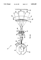
- FIG. 1A is a schematic diagram showing one embodiment of the scanning optical system of the present invention.
- FIG. 1B shows an alternative positioning of the light beam and rotating polygonal mirror illustrated in the system of FIG. 1A;
- FIGS. 2A, 2B and 2C illustrate in detail the reflecting of the incident beam by the reflective surfaces of the rotating polygonal mirror shown in FIG. 1B and the longitudinal shifting of the entrance pupil due to rotation of the polygonal mirror;
- FIG. 3 is a graph showing the field curvature induced by the longitudinal shift in the entrance pupil position as the polygonal mirror rotates
- FIG. 4 is a graph showing the field curvature for the swept beam following correction by the Petzval curvature of the beam expander eyepiece lens
- FIG. 5 is a schematic diagram showing another embodiment of the scanning optical system of the present invention.
- FIG. 6 is a schematic diagram showing another embodiment of the scanning optical system of the present invention.
- FIGS. 1A and 1B wherein there is illustrated the scanning optical system 10 of the present invention.
- a collimated light beam 12 emitted from a source 14 is directed to a polygonal mirror 16 comprised of a plurality of precisely angled reflective surfaces (or facets) 18 assembled about an axis 20 in an equilateral polygon configuration.
- a motor 22 having a shaft (not shown) mounted to the polygonal mirror 16 at the axis 20 thereof causes the polygonal mirror to rotate about the axis in the direction indicated by the arrow 24.
- each reflective surface 18 With rotation of the polygonal mirror 16, the inclination (or angle) of each reflective surface 18 with respect to the position of the light beam 12 changes from a starting inclination angle 26 through a center inclination angle 28 to an ending inclination angle 30.
- the light beam 12 is directed at the polygonal mirror 16 but is offset from the axis 20.
- the light beam 12 is aimed directly at the axis 20 of the polygonal mirror 16.
- the incident light beam 12 will be orthogonal to the reflective surface 18 at the center inclination angle 28.
- the reflective surface 18 moves away from the light beam 12 (following the ending angle 30) and the next reflective surface on the polygonal mirror moves into position (at the starting angle 26) to reflect the light beam.
- the rotation of the polygonal mirror 16 and movement of a reflective surface 18 from the starting through ending inclination angles (26 through 28 to 30) causes the light beam 12 to be reflected and generate a reflected beam 32 that is swept by the rotation of the polygonal mirror through a predetermined arc 34 (in the direction indicated by the arrow head 36).
- the reflected light beam 32 sweeps through the arc 34 from a starting sweep position 38 through a center sweep position 40 to an ending sweep position 42 corresponding to the starting, center and ending inclination angles 26, 28 and 30, respectively, for the reflective surface 18.
- subsequent reflective surfaces 18 sequentially move into position to reflect the light beam 12 causing the reflected light beam 32 to be repetitively swept through the arc 34.
- the optical system 10 further includes beam expander optics 44 comprising an eyepiece lens 46 and an objective lens 48.
- the eyepiece lens 46 and objective lens 48 may each include a plurality of lenses and that the single lenses shown for each in FIG. 1A are illustrative only.
- the beam expander optics 44 are optically positioned in the swept light path of the reflected light beam 32 such that the eyepiece lens 46 focuses the reflected beam and the objective lens 48 expands and collimates the reflected beam to generate a scanning beam 50.
- the beam expander optics 44 function to demagnify the sweep angle of the reflected light beam 32 associated with the arc 34 to repetitively project the scanning beam 50 through an arc 59 across the surface of an object 58 in the direction indicated by the arrow head 60 from a starting scan position 52 through a center scan position 54 to an ending scan position 56 (that correspond to the starting, center and ending sweep positions, 38, 40 and 42, respectively).
- the nature of the beam expander optics 44 reverses the image of the swept beam 32 such that the direction 60 of the sweep of the scanning beam 50 is opposite than the direction 36 of the swept beam 32.
- the beam expander optics 44 further function to magnify the diameter of the scanning beam 50 projected on the object 58 or alternatively focus the scanning beam to a spot on the surface of the object if desired.
- FIGS. 2A, 2B and 2C there are shown a series of illustrations detailing the reflection of the incident light beam 12, having, by the orientation shown in FIG. 1B, the reflective surfaces 18 of the rotating polygonal mirror 16.
- FIG. 2A illustrates such reflection when the reflective surface 18 is at the starting angle 26.
- FIG. 2B illustrates such reflection when the reflective surface 18 is at the center angle 28 and orthogonal to the light beam 12.
- FIG. 2C illustrates such reflection when the reflective surface 18 is at the ending angle 30. It will, of course, be understood that the dimensions illustrated in FIGS. 2A, 2B and 2C are exaggerated to facilitate a more complete understanding of the reflection process.
- An entrance pupil 62 for the eyepiece lens 46 that focuses the reflected light beam 32 is projected on the reflective surface 18 of the polygonal mirror at the point where the light beam 12 is reflected.
- Rotation of the polygonal mirror 16 such that the reflective surface 18 moves from the starting angle 26 through the center angle 28 to the ending angle 30 causes the position of the entrance pupil 62 to shift as shown at 64 in longitudinal relation to the light path for the light beam 12.
- the shifting of the position of the entrance pupil 62 due to rotation of the polygonal mirror 16 causes field curvature in the image plane 66 (FIGS. 1A and 1B) of the afocal eyepiece lens 46 that adversely distorts the reflected light beam 32.
- the amount (x) of longitudinal shift 64 (and hence the induced distortion in the image plane) is determined by the dimensions of the polygonal mirror 16 according to the following equation: ##EQU1##
- the amount of longitudinal shift 64 (corresponding to the induced field curvature at the image plane 66) varies as a function of the rotation of the polygonal mirror 16 according to the following equation based on equation (1):
- the eyepiece lens 46 is modified by adding a Petzval curvature (a third order Seidel aberration) thereto.
- the Petzval curvature (p) for the eyepiece lens 46 is given according to the following equation:
- equation (9) yields:
- the amount of Petzval curvature (p) should vary as a function of the rotation of the polygonal mirror 16 to substantially cancel the distortion induced by the longitudinal shift in the entrance pupil according to the following equation based on equation (8):
- f is determined from equation (10).
- the effective distortion due to longitudinal shift (corresponding to the corrected field curvature at the image plane 66) is determined according to the following equation based on equations (5) and (11):
- n 1.51.
- the longitudinal pupil shift 64 (x) is equal to 5.147 millimeters.
- a graph showing the variation in the amount of induced field curvature according to equation (5) as the polygonal mirror 16 rotates is shown in FIG. 3 with the calculated values of x i shown in column 3 of Table 1.
- the Petzval curvature requires a focal length (f) according to equation (10) of 351.356 millimeters.
- the calculated values of the Petzval curvature p i according to equation (11) are shown in column 4 of Table 1.
- a graph showing the effective induced field curvature (x i ) following correction of the longitudinal pupil shift by the Petzval curvature according to equation (12) is shown in FIG.
- FIGS. 3 and 4 and Table 1 illustrate that approximately ninety-nine percent of the induced field curvature (x i ) in this example is eliminated (x i ) through cancellation by the included Petzval aberration (p i ).
- FIG. 5 there is shown another embodiment of the scanning optical system 10' of the present invention wherein the scanning light beam 50 is directed back toward the rotating polygonal mirror 16 by a pair of reflecting mirrors 68. Movement of the scanning light beam 50 from the starting scan position 52 through the center scan position 54 to the ending scan position 56 tracks and corresponds with the inclination movement of a reflective surface 18' on the polygonal mirror 16 from a starting, center and ending angles 26', 28' and 30', respectively.
- the beam expander optics 44 function to magnify the diameter of the projected scanning beam 50 and decrease the scanning angle arc. Preferably, the diameter of the scanning beam is magnified to be substantially equal to the length of the reflective surface 18'.
- Movement of the reflective surface 18' due to rotation of the polygonal mirror 16 causes the scanning beam 50 to be reflected and generate a secondary reflected beam 70 that is swept by the rotation of the polygonal mirror through an arc 72 (in the direction indicated by the arrow head 74).
- the secondary reflected light beam 70 sweeps through the arc 72 from a starting secondary sweep position 76 through a center secondary sweep position 78 to an ending secondary sweep position 80 corresponding to the starting, center and ending angles 26', 28' and 30', respectively, for the reflective surface 18'.
- subsequent reflective surfaces 18' move into position to reflect the scanning beam 50 causing the secondary reflected light beam 70 to be repetitively swept through the arc 72.
- the optical system 10' further includes focusing optics 82 comprising a focusing lens 84.
- the focusing lens 84 may include a plurality of lenses and that the single lens shown in FIG. 5 is illustrative only it will, of course, further be understood that focusing optics 82 may not be required in every application of the system 10'.
- the focusing optics 82 are optically positioned in the light path of the secondary reflected light beam 70 to generate a secondary scanning beam 86 such that the focusing lens 84 focuses the secondary reflected beam to a spot on the surface of the object 58.
- the focusing optics 82 further function to project the secondary scanning beam 86 from a starting secondary scan position 88 through a center secondary scan position 90 to an ending secondary scan position 92 (that correspond with the starting, center and ending secondary sweep positions, 76, 78 and 80, respectively) parallel to each other to repetitively scan across the surface of the object 58 in the direction indicated by the arrow 94.
- the embodiments disclosed above utilize a single rotating polygonal mirror 16 in either a single reflection (FIGS. 1A and 1B) or double reflection (FIG. 5) operation. It will, of course, be understood that two separate rotating polygonal mirrors 16 and 16' having corresponding reflective surfaces 18 and 18' therein as in FIG. 6, may be provided in another embodiment of the scanning optical system 10" for double reflection operation.
- the reflective surfaces 18 of the first polygonal mirror 16 need not be the same size as the reflective surfaces 18' of the second polygonal mirror 16' provided the relative rates of rotation of the polygonal mirrors are adjusted to account for the different reflective surface sizes and the magnification of the beam expander optics is adjusted to properly size the diameter of the scanning beam 50 incident on the second polygonal mirror. Synchronization and adjustment of the rotation of the polygonal mirrors 16 and 16' is provided by the synch means 96 coupled to the motors 22 and 22' of each polygonal mirror.
Landscapes
- Physics & Mathematics (AREA)
- General Physics & Mathematics (AREA)
- Optics & Photonics (AREA)
- Mechanical Optical Scanning Systems (AREA)
- Lenses (AREA)
Abstract
Description
x.sub.i =[R/cos(α.sub.i)]-R (5)
α.sub.i =(α*i)/10.
p=(-1/2)*[h.sup.2 /(f*n)] (6)
h=f*tan(α), (7)
n=refractive index, and
f=eyepiece lens 46 focal length.
p=(-1/2)*[(f*tan(α).sup.2)/n]. (8)
f=-2*p*n/tan(α).sup.2. (9)
f=2*x*n/tan(α).sup.2. (10)
p.sub.i =(-1/2)*[(f*tan(α.sub.i).sup.2)/n] (11)
x.sub.i =x.sub.i +P.sub.i (12)
              TABLE 1
______________________________________
        α.sub.i
                 x.sub.i     p.sub.i x.sub.i
i       (radians)
                 (mm)        (mm)    (mm)
______________________________________
0       .000000   .000000      .000000
                                     .000000
1       .020732   .050587     -.050020
                                     .000567
2       .041463   .202238     -.200244
                                     .001994
3       .062194   .455584     -.451189
                                     .004395
4       .082926   .811044     -.803741
                                     .007303
5       .103657  1.269540    -1.259089
                                     .010451
6       .124389  1.831553    -1.818865
                                     .012688
7       .145120  2.498788    -2.484978
                                     .013810
8       .165852  3.272762    -3.259849
                                     .012913
9       .186583  4.154797    -4.146166
                                     .008631
10      .207315  5.147241    -5.147212
                                     .000029
______________________________________
Claims (10)
Priority Applications (3)
| Application Number | Priority Date | Filing Date | Title |
|---|---|---|---|
| US07/963,549 US5392149A (en) | 1992-10-20 | 1992-10-20 | Polygonal mirror optical scanning system |
| US08/330,834 US5585955A (en) | 1992-10-20 | 1994-10-27 | Polygonal mirror optical scanning system |
| US08/555,861 US5726793A (en) | 1992-10-20 | 1995-11-13 | Polygonal mirror optical scanning system |
Applications Claiming Priority (1)
| Application Number | Priority Date | Filing Date | Title |
|---|---|---|---|
| US07/963,549 US5392149A (en) | 1992-10-20 | 1992-10-20 | Polygonal mirror optical scanning system |
Related Child Applications (1)
| Application Number | Title | Priority Date | Filing Date |
|---|---|---|---|
| US08/330,834 Division US5585955A (en) | 1992-10-20 | 1994-10-27 | Polygonal mirror optical scanning system |
Publications (1)
| Publication Number | Publication Date |
|---|---|
| US5392149A true US5392149A (en) | 1995-02-21 |
Family
ID=25507377
Family Applications (3)
| Application Number | Title | Priority Date | Filing Date |
|---|---|---|---|
| US07/963,549 Expired - Fee Related US5392149A (en) | 1992-10-20 | 1992-10-20 | Polygonal mirror optical scanning system |
| US08/330,834 Expired - Fee Related US5585955A (en) | 1992-10-20 | 1994-10-27 | Polygonal mirror optical scanning system |
| US08/555,861 Expired - Lifetime US5726793A (en) | 1992-10-20 | 1995-11-13 | Polygonal mirror optical scanning system |
Family Applications After (2)
| Application Number | Title | Priority Date | Filing Date |
|---|---|---|---|
| US08/330,834 Expired - Fee Related US5585955A (en) | 1992-10-20 | 1994-10-27 | Polygonal mirror optical scanning system |
| US08/555,861 Expired - Lifetime US5726793A (en) | 1992-10-20 | 1995-11-13 | Polygonal mirror optical scanning system |
Country Status (1)
| Country | Link |
|---|---|
| US (3) | US5392149A (en) |
Cited By (13)
| Publication number | Priority date | Publication date | Assignee | Title |
|---|---|---|---|---|
| US5532730A (en) * | 1993-10-06 | 1996-07-02 | Konica Corporation | Light beam scanning apparatus |
| EP0775928A2 (en) * | 1995-11-24 | 1997-05-28 | Seiko Epson Corporation | Optical scanner |
| US5646791A (en) * | 1995-01-04 | 1997-07-08 | Visx Incorporated | Method and apparatus for temporal and spatial beam integration |
| EP0825468A2 (en) * | 1996-08-21 | 1998-02-25 | Seiko Epson Corporation | Optical scanner |
| JPH10239616A (en) * | 1997-02-28 | 1998-09-11 | Seiko Epson Corp | Optical scanner |
| US6053409A (en) * | 1996-03-07 | 2000-04-25 | Accu-Sort Systems, Inc. | Dynamic focusing apparatus for an optical imaging system using a deformable mirror |
| US6445483B2 (en) * | 1996-07-01 | 2002-09-03 | Seiko Epson Corporation | Optical scanning apparatus |
| JP2005165340A (en) * | 1995-11-24 | 2005-06-23 | Seiko Epson Corp | Optical scanner |
| US20140063214A1 (en) * | 2012-08-28 | 2014-03-06 | Commissariat A I'energie Atomique Et Aux Energies Alternatives | Imaging device with a wide viewing angle |
| WO2017170513A1 (en) * | 2016-03-30 | 2017-10-05 | 株式会社ニコン | Beam scanning device and pattern rendering apparatus |
| US10977770B2 (en) | 2019-03-11 | 2021-04-13 | Samsung Electronics Co., Ltd. | Display apparatus capable of laterally shifting image |
| US20210286172A1 (en) * | 2020-03-11 | 2021-09-16 | Rohr, Inc. | Substrate perforation system & method using polygon mirror(s) |
| US11852805B2 (en) | 2021-01-05 | 2023-12-26 | Raytheon Company | Wave scanning optic |
Families Citing this family (18)
| Publication number | Priority date | Publication date | Assignee | Title |
|---|---|---|---|---|
| US5701132A (en) * | 1996-03-29 | 1997-12-23 | University Of Washington | Virtual retinal display with expanded exit pupil |
| US5933230A (en) * | 1997-04-28 | 1999-08-03 | International Business Machines Corporation | Surface inspection tool |
| JP3259657B2 (en) * | 1997-04-30 | 2002-02-25 | キヤノン株式会社 | Projection exposure apparatus and device manufacturing method using the same |
| JP3937580B2 (en) | 1998-04-30 | 2007-06-27 | キヤノン株式会社 | Projection exposure apparatus and device manufacturing method using the same |
| US6243189B1 (en) * | 1999-04-20 | 2001-06-05 | Alfonso Carlos Ribes | Inexpensive, high quality scanning system |
| US6542304B2 (en) * | 1999-05-17 | 2003-04-01 | Toolz, Ltd. | Laser beam device with apertured reflective element |
| US6396616B1 (en) | 2000-10-10 | 2002-05-28 | 3M Innovative Properties Company | Direct laser imaging system |
| US6954308B2 (en) * | 2001-11-02 | 2005-10-11 | Microvision, Inc. | Apparatus and methods for generating multiple exit-pupil images in an expanded exit pupil |
| US6768588B2 (en) | 2001-11-02 | 2004-07-27 | Microvision, Inc. | Apparatus and methods for generating multiple exit-pupil images in an expanded exit pupil |
| US7339737B2 (en) * | 2004-04-23 | 2008-03-04 | Microvision, Inc. | Beam multiplier that can be used as an exit-pupil expander and related system and method |
| CN100514174C (en) * | 2004-11-19 | 2009-07-15 | 杨东佐 | Image projecting system and light operating method |
| US8679102B2 (en) | 2011-02-03 | 2014-03-25 | Tria Beauty, Inc. | Devices and methods for radiation-based dermatological treatments |
| US11406448B2 (en) | 2011-02-03 | 2022-08-09 | Channel Investments, Llc | Devices and methods for radiation-based dermatological treatments |
| KR102011298B1 (en) | 2011-02-03 | 2019-10-14 | 트리아 뷰티, 인코포레이티드 | Radiation-based dermatological devices and methods |
| US9308390B2 (en) | 2011-02-03 | 2016-04-12 | Tria Beauty, Inc. | Devices and methods for radiation-based dermatological treatments |
| US9789332B2 (en) | 2011-02-03 | 2017-10-17 | Tria Beauty, Inc. | Devices and methods for radiation-based dermatological treatments |
| US8685008B2 (en) * | 2011-02-03 | 2014-04-01 | Tria Beauty, Inc. | Devices and methods for radiation-based dermatological treatments |
| JP7136601B2 (en) * | 2018-06-25 | 2022-09-13 | 川崎重工業株式会社 | Light guide device and laser processing device |
Citations (10)
| Publication number | Priority date | Publication date | Assignee | Title |
|---|---|---|---|---|
| US3972583A (en) * | 1972-01-25 | 1976-08-03 | Redifon Limited | Scanning devices |
| US3973826A (en) * | 1972-01-25 | 1976-08-10 | Redifon Limited | Scanning devices |
| US4030806A (en) * | 1974-09-11 | 1977-06-21 | Canon Kabushiki Kaisha | Scanning optical system |
| US4129355A (en) * | 1976-07-02 | 1978-12-12 | Fuji Photo Film Co., Ltd. | Light beam scanner with parallelism error correction |
| US4508422A (en) * | 1982-03-03 | 1985-04-02 | Pharos Ab | Optical scanning system |
| US4537465A (en) * | 1981-11-12 | 1985-08-27 | Lincoln Laser Company | Apparatus with two input beams for generating optical scans |
| US4624528A (en) * | 1985-02-21 | 1986-11-25 | Xerox Corporation | Scanning systems with polygon scanner having curved facets |
| US4682842A (en) * | 1984-08-31 | 1987-07-28 | Xerox Corporation | Scanning system with two reflections from scanning surface by mirrors with optical power |
| US4805974A (en) * | 1987-11-02 | 1989-02-21 | Xerox Corporation | Polycone™ scanning system with multiple beams |
| US4870273A (en) * | 1987-08-07 | 1989-09-26 | Xerox Corporation | Jitter reduction in rotating polygon scanning systems |
Family Cites Families (3)
| Publication number | Priority date | Publication date | Assignee | Title |
|---|---|---|---|---|
| US4099829A (en) * | 1977-02-23 | 1978-07-11 | Harris Corporation | Flat field optical scanning system |
| US5013133A (en) * | 1988-10-31 | 1991-05-07 | The University Of Rochester | Diffractive optical imaging lens systems |
| US5200861A (en) * | 1991-09-27 | 1993-04-06 | U.S. Precision Lens Incorporated | Lens systems |
-
1992
- 1992-10-20 US US07/963,549 patent/US5392149A/en not_active Expired - Fee Related
-
1994
- 1994-10-27 US US08/330,834 patent/US5585955A/en not_active Expired - Fee Related
-
1995
- 1995-11-13 US US08/555,861 patent/US5726793A/en not_active Expired - Lifetime
Patent Citations (10)
| Publication number | Priority date | Publication date | Assignee | Title |
|---|---|---|---|---|
| US3972583A (en) * | 1972-01-25 | 1976-08-03 | Redifon Limited | Scanning devices |
| US3973826A (en) * | 1972-01-25 | 1976-08-10 | Redifon Limited | Scanning devices |
| US4030806A (en) * | 1974-09-11 | 1977-06-21 | Canon Kabushiki Kaisha | Scanning optical system |
| US4129355A (en) * | 1976-07-02 | 1978-12-12 | Fuji Photo Film Co., Ltd. | Light beam scanner with parallelism error correction |
| US4537465A (en) * | 1981-11-12 | 1985-08-27 | Lincoln Laser Company | Apparatus with two input beams for generating optical scans |
| US4508422A (en) * | 1982-03-03 | 1985-04-02 | Pharos Ab | Optical scanning system |
| US4682842A (en) * | 1984-08-31 | 1987-07-28 | Xerox Corporation | Scanning system with two reflections from scanning surface by mirrors with optical power |
| US4624528A (en) * | 1985-02-21 | 1986-11-25 | Xerox Corporation | Scanning systems with polygon scanner having curved facets |
| US4870273A (en) * | 1987-08-07 | 1989-09-26 | Xerox Corporation | Jitter reduction in rotating polygon scanning systems |
| US4805974A (en) * | 1987-11-02 | 1989-02-21 | Xerox Corporation | Polycone™ scanning system with multiple beams |
Cited By (27)
| Publication number | Priority date | Publication date | Assignee | Title |
|---|---|---|---|---|
| US5532730A (en) * | 1993-10-06 | 1996-07-02 | Konica Corporation | Light beam scanning apparatus |
| US5646791A (en) * | 1995-01-04 | 1997-07-08 | Visx Incorporated | Method and apparatus for temporal and spatial beam integration |
| US5912775A (en) * | 1995-01-04 | 1999-06-15 | Visx, Incorporated | Method and apparatus for temporal and spatial beam integration |
| EP0775928A2 (en) * | 1995-11-24 | 1997-05-28 | Seiko Epson Corporation | Optical scanner |
| JP2005165340A (en) * | 1995-11-24 | 2005-06-23 | Seiko Epson Corp | Optical scanner |
| EP1195636A3 (en) * | 1995-11-24 | 2004-05-26 | Seiko Epson Corporation | Optical scanner |
| US5764397A (en) * | 1995-11-24 | 1998-06-09 | Seiko Epson Corporation | Optical scanner |
| EP0775928A3 (en) * | 1995-11-24 | 1999-04-21 | Seiko Epson Corporation | Optical scanner |
| EP1195636A2 (en) * | 1995-11-24 | 2002-04-10 | Seiko Epson Corporation | Optical scanner |
| US6053409A (en) * | 1996-03-07 | 2000-04-25 | Accu-Sort Systems, Inc. | Dynamic focusing apparatus for an optical imaging system using a deformable mirror |
| US6445483B2 (en) * | 1996-07-01 | 2002-09-03 | Seiko Epson Corporation | Optical scanning apparatus |
| EP0825468A2 (en) * | 1996-08-21 | 1998-02-25 | Seiko Epson Corporation | Optical scanner |
| EP0825469A3 (en) * | 1996-08-21 | 1999-05-06 | Seiko Epson Corporation | Optical scanner |
| EP0825468A3 (en) * | 1996-08-21 | 1999-04-21 | Seiko Epson Corporation | Optical scanner |
| EP0825469A2 (en) * | 1996-08-21 | 1998-02-25 | Seiko Epson Corporation | Optical scanner |
| JPH10239616A (en) * | 1997-02-28 | 1998-09-11 | Seiko Epson Corp | Optical scanner |
| US20140063214A1 (en) * | 2012-08-28 | 2014-03-06 | Commissariat A I'energie Atomique Et Aux Energies Alternatives | Imaging device with a wide viewing angle |
| WO2017170513A1 (en) * | 2016-03-30 | 2017-10-05 | 株式会社ニコン | Beam scanning device and pattern rendering apparatus |
| CN108885337A (en) * | 2016-03-30 | 2018-11-23 | 株式会社尼康 | Light-beam scanner and pattern plotter device |
| TWI714745B (en) * | 2016-03-30 | 2021-01-01 | 日商尼康股份有限公司 | Beam scanning device and pattern drawing device |
| CN108885337B (en) * | 2016-03-30 | 2021-06-04 | 株式会社尼康 | Light beam scanning device and pattern drawing device |
| KR20220000414A (en) * | 2016-03-30 | 2022-01-03 | 가부시키가이샤 니콘 | Beam scanning device and pattern rendering apparatus |
| US10977770B2 (en) | 2019-03-11 | 2021-04-13 | Samsung Electronics Co., Ltd. | Display apparatus capable of laterally shifting image |
| US11682104B2 (en) | 2019-03-11 | 2023-06-20 | Samsung Electronics Co., Ltd. | Display apparatus capable of laterally shifting image |
| US20210286172A1 (en) * | 2020-03-11 | 2021-09-16 | Rohr, Inc. | Substrate perforation system & method using polygon mirror(s) |
| US11237386B2 (en) * | 2020-03-11 | 2022-02-01 | Rohr, Inc. | Substrate perforation system and method using polygon mirror(s) |
| US11852805B2 (en) | 2021-01-05 | 2023-12-26 | Raytheon Company | Wave scanning optic |
Also Published As
| Publication number | Publication date |
|---|---|
| US5585955A (en) | 1996-12-17 |
| US5726793A (en) | 1998-03-10 |
Similar Documents
| Publication | Publication Date | Title |
|---|---|---|
| US5392149A (en) | Polygonal mirror optical scanning system | |
| US4123135A (en) | Optical system for rotating mirror line scanning apparatus | |
| EP0028160B1 (en) | Flying spot optical scanner systems | |
| JPS588B2 (en) | Hikari Bee Mususasouchi | |
| US4512625A (en) | Scanner optics with no cross scan field curvature | |
| JPH0658561B2 (en) | Optical scanning system for a laser diode printer utilizing the path of a folded light beam | |
| US4796962A (en) | Optical scanner | |
| JPH0672981B2 (en) | Optical beam scanning optical system | |
| US5726433A (en) | Optical scanning apparatus for generating a helical scanning pattern on an external (cylindrical) surface | |
| US4796965A (en) | Optical scanning device | |
| JPH03116112A (en) | Scanning type optical device | |
| JPH01149010A (en) | Rotary mirror scanner | |
| US4029389A (en) | Radiation scanning system | |
| EP0629891B1 (en) | Beam scanning apparatus | |
| JPH0644108B2 (en) | A shake correction device that does not cause a bow due to two reflections on one surface | |
| US4870273A (en) | Jitter reduction in rotating polygon scanning systems | |
| US4898437A (en) | Wobble correction by two reflections on a facet without bow | |
| US5650871A (en) | Single element optics for passive facet tracking | |
| US5136416A (en) | Optical scanning unit for use in laser beam printer or the like | |
| JPH037082B2 (en) | ||
| JPH0980330A (en) | Multibeam scanning optical system | |
| JPH0588100A (en) | Scanner | |
| JP2583716B2 (en) | Optical system laser beam scanner | |
| GB1567319A (en) | Optical apparatus | |
| JPS5820405B2 (en) | Hikari Bee Mususasouchi |
Legal Events
| Date | Code | Title | Description |
|---|---|---|---|
| AS | Assignment |
Owner name: E-SYSTEMS, INC., TEXAS Free format text: ASSIGNMENT OF ASSIGNORS INTEREST.;ASSIGNORS:BOARDMAN, JOHN D.;BOYD, JAMES R.;WELCH, JEFFREY P.;REEL/FRAME:006392/0903 Effective date: 19921012 |
|
| CC | Certificate of correction | ||
| FPAY | Fee payment |
Year of fee payment: 4 |
|
| AS | Assignment |
Owner name: RAYTHEON E-SYSTEMS, INC., A CORP. OF DELAWARE, TEX Free format text: CHANGE OF NAME;ASSIGNOR:E-SYSTEMS, INC.;REEL/FRAME:009507/0603 Effective date: 19960703 |
|
| AS | Assignment |
Owner name: RAYTHEON COMPANY, A CORP. OF DELAWARE, MASSACHUSET Free format text: ASSIGNMENT OF ASSIGNORS INTEREST;ASSIGNOR:RAYTHEON E-SYSTEMS, INC., A CORP. OF DELAWARE;REEL/FRAME:009570/0001 Effective date: 19981030 |
|
| REMI | Maintenance fee reminder mailed | ||
| LAPS | Lapse for failure to pay maintenance fees | ||
| LAPS | Lapse for failure to pay maintenance fees |
Free format text: PATENT EXPIRED FOR FAILURE TO PAY MAINTENANCE FEES (ORIGINAL EVENT CODE: EXP.); ENTITY STATUS OF PATENT OWNER: LARGE ENTITY |
|
| STCH | Information on status: patent discontinuation |
Free format text: PATENT EXPIRED DUE TO NONPAYMENT OF MAINTENANCE FEES UNDER 37 CFR 1.362 |
|
| FP | Lapsed due to failure to pay maintenance fee |
Effective date: 20030221 |
|
| AS | Assignment |
Owner name: OL SECURITY LIMITED LIABILITY COMPANY, DELAWARE Free format text: ASSIGNMENT OF ASSIGNORS INTEREST;ASSIGNOR:RAYTHEON COMPANY;REEL/FRAME:029215/0160 Effective date: 20120730 |