EP3708992B1 - Schätzvorrichtung, schätzverfahren und programmspeichermedium - Google Patents
Schätzvorrichtung, schätzverfahren und programmspeichermedium Download PDFInfo
- Publication number
- EP3708992B1 EP3708992B1 EP18875039.2A EP18875039A EP3708992B1 EP 3708992 B1 EP3708992 B1 EP 3708992B1 EP 18875039 A EP18875039 A EP 18875039A EP 3708992 B1 EP3708992 B1 EP 3708992B1
- Authority
- EP
- European Patent Office
- Prior art keywords
- pipe
- frequency response
- strength
- estimating
- rigidity variable
- Prior art date
- Legal status (The legal status is an assumption and is not a legal conclusion. Google has not performed a legal analysis and makes no representation as to the accuracy of the status listed.)
- Active
Links
Images





Classifications
-
- G—PHYSICS
- G01—MEASURING; TESTING
- G01M—TESTING STATIC OR DYNAMIC BALANCE OF MACHINES OR STRUCTURES; TESTING OF STRUCTURES OR APPARATUS, NOT OTHERWISE PROVIDED FOR
- G01M5/00—Investigating the elasticity of structures, e.g. deflection of bridges or air-craft wings
- G01M5/0025—Investigating the elasticity of structures, e.g. deflection of bridges or air-craft wings of elongated objects, e.g. pipes, masts, towers or railways
-
- G—PHYSICS
- G01—MEASURING; TESTING
- G01M—TESTING STATIC OR DYNAMIC BALANCE OF MACHINES OR STRUCTURES; TESTING OF STRUCTURES OR APPARATUS, NOT OTHERWISE PROVIDED FOR
- G01M5/00—Investigating the elasticity of structures, e.g. deflection of bridges or air-craft wings
- G01M5/0066—Investigating the elasticity of structures, e.g. deflection of bridges or air-craft wings by exciting or detecting vibration or acceleration
-
- G—PHYSICS
- G01—MEASURING; TESTING
- G01M—TESTING STATIC OR DYNAMIC BALANCE OF MACHINES OR STRUCTURES; TESTING OF STRUCTURES OR APPARATUS, NOT OTHERWISE PROVIDED FOR
- G01M7/00—Vibration-testing of structures; Shock-testing of structures
- G01M7/08—Shock-testing
-
- G—PHYSICS
- G01—MEASURING; TESTING
- G01N—INVESTIGATING OR ANALYSING MATERIALS BY DETERMINING THEIR CHEMICAL OR PHYSICAL PROPERTIES
- G01N3/00—Investigating strength properties of solid materials by application of mechanical stress
- G01N3/32—Investigating strength properties of solid materials by application of mechanical stress by applying repeated or pulsating forces
Definitions
- the present invention relates to a technique of estimating strength of a pipe.
- PTL 1 describes a buried-pipe inspection method of inspecting, with high accuracy, a degree of deterioration of a buried pipe such as a buried pipe and a ceramic pipe forming a sewer pipeline, an agricultural water pipeline, and the like, by performing an impact elastic wave test.
- WO 2016/194331 A1 further discloses a model data calculating means for calculating theoretical values of vibration propagation velocities corresponding to measured values of the plurality of vibration frequencies, which model comprises the Young's modulus as parameter.
- the inspection method of a buried pipe described in PTL 1 is a method in which a deterioration state of a buried pipe is inspected from an inside of the pipe.
- a pipe hereinafter, referred to as a "water-filled pipe”
- water-filled pipe like a water supply pipe in which the inside of the pipe is filled with a fluid such as water, it is not easy to inspect a deterioration state from the inside of the pipe.
- the present invention is made for solving the above-described problem, and a main object of the present invention is to provide an estimating device and the like that are capable of easily estimating strength of a water-filled pipe.
- An estimating device is defined in independent claim 1.
- An estimating method according to one aspect of the present invention is defined in independent claim 6.
- a program according to one aspect of the present invention is defined in independent claim 7.
- an estimating device and the like that are able to estimate strength of a water-filled pipe with ease can be provided.
- FIG. 1 is a diagram illustrating an estimating device according to the first example embodiment of the present invention.
- an estimating device 100 includes a frequency response calculating unit 110, a pipe rigidity variable estimating unit 120, and a strength estimating unit 130.
- the frequency response calculating unit 110 calculates, based on an excitation force when a pipe is excited and a vibration response propagating through the pipe, a frequency response function of the pipe.
- the pipe rigidity variable estimating unit 120 estimates, based on a frequency response function model representing a frequency response of the pipe, and the calculated frequency response function, a parameter relating to rigidity of the pipe.
- the strength estimating unit 130 estimates, based on a relation between the estimated parameter and strength of the pipe, strength of the pipe.
- Fig. 2 is an example of a case in which strength of a pipe 301 being a part of a water-supply network is estimated. Specifically, in the example illustrated in Fig. 2 , the estimating device 100 estimates strength of the pipe 301. Note that, in the following example embodiment, a case in which the estimating device 100 estimates strength of a pipe configuring a water pipe is described as an example. Further, the pipe 301 is assumed to be the water-filled pipe described above. Specifically, a case in which the inside of the pipe 301 is filled with water by applying pressure to the water, or the water flowing into the pipe due to gravity is assumed. A main target of strength estimation by the estimating device 100 is a water-filled pipe.
- the pipe 301 is buried underground. Specifically, in the example illustrated in Fig. 2 , the pipe 301 is assumed to be disposed in such a way that visual observation and contact of the pipe 301 is difficult in a normal condition. Further, accessories 302-1 and 302-2 are installed on the pipe 301. Each of the accessories 302-1 and 302-2 is, for example, a fire hydrant, an air valve, or a gate valve, but may be another equipment attached to the pipe. Each of the accessories 302-1 and 302-2 is installed in a manhole. Specifically, in the example illustrated in Fig. 2 , each of the accessories 302-1 and 302-2 is assumed to be disposed at a position where a contact can be made in a normal condition.
- an instrument for acquiring data required when strength of the pipe 301 is estimated by the estimating device 100 is installed on each of the accessories 302-1 and 302-2.
- An exciter 161 is installed on the accessory 302-1.
- the exciter 161 excites, for example, the accessory 302-1.
- an elastic wave is excited in the fluid such as water filled inside the pipe 301.
- the elastic wave is also excited in the pipe 301.
- the exciter 16 a mechanism that is capable of exciting a vibration of a broad bandwidth is desirably used.
- the exciter 161 for example, an impulse hammer, a hydraulic actuator, a pneumatic actuator, or a water-releasing pressure-variation generator is used, but another mechanism may be used as the exciter 161.
- Excitation force data which are data recording the excitation force, are sent to, for example, the frequency response calculating unit 110 of the estimating device 100 via a wired or wireless communication network or another mechanism for data transmission.
- a measuring instrument 162 is installed on the accessory 302-2.
- the measuring instrument 162 measures an elastic wave propagating through the fluid such as water inside the pipe 301 and the pipe 301.
- the measuring instrument 162 mainly measures an elastic wave generated by excitation by the exciter 161 and propagating through the fluid such as water inside the pipe 301 and the pipe 301.
- a sensor for measuring a vibration of a solid body is used.
- the measuring instrument 162 include a piezoelectric type acceleration sensor, a capacitive type acceleration sensor, an optical velocity sensor, a dynamic strain sensor, an eddy-current displacement sensor, a dial gauge, a digital image correlation measuring device, an optical fiber type strain gauge, a contact type displacement sensor, and a speckle light interferometer.
- another instrument may be used as the measuring instrument 162.
- a measurement result by the measuring instrument 162 is sent to, for example, the frequency response calculating unit 110 of the estimating device 100 via a wired or wireless communication network or another mechanism for data transmission.
- the measuring instrument 162 may send a result of a measurement performed for a time period from before to after the time point to each component of the estimating device 100.
- a length of the time period from before to after the reference time point at which the exciter 161 performs the excitation may be determined according to a time required for an elastic wave generated by the excitation to the accessory 302-1 by the exciter 161 to propagate to the measuring instrument 162.
- the pipe 301 is assumed to be buried underground, and visual observation and contact of the pipe 301 is assumed to be difficult. Therefore, the exciter 161 and the measuring instrument 162 are exemplified in such a way as to be attached to the accessories 302. However, when it is possible to make contact with the pipe 301, each of the exciter 161 and the measuring instrument 162 may be directly installed on, for example, the pipe 301.
- each component of the estimating device 100 represents a block of a function unit. Some or all of each component of each device is achieved by, for example, any combination of an information processing device 500 and a program, such as illustrated in Fig. 9 .
- the information processing device 500 includes, as one example, a configuration as follows.
- Each component of each device according to each example embodiment is achieved by the CPU 501 acquiring and executing the program 504 achieving a function of each component.
- the program 504 achieving a function of each component of each device is, for example, previously stored in the storing device 505 or the RAM 503, and read out by the CPU 501 as necessary.
- the program 504 may be provided to the CPU 501 via the communication network 509, or may be previously stored in the recording medium 506, read out by the drive device 507, and thereby provided to the CPU 501.
- each device may be achieved by any combination of the information processing device 500 that is separated for each component and a program. Further, a plurality of components included in each device may be achieved by any combination of one information processing device 500 and a program.
- each component of each device is achieved by a dedicated or general-purpose circuit including a processor and the like, or a combination thereof.
- the dedicated or general-purpose circuit may be configured by a single chip, or may be configured by a plurality of chips connected to each other via a bus.
- Some or all of each component of each device may be achieved by a combination of the above-described circuit and the like and a program.
- each component of each device is achieved by a plurality of information processing devices and circuits and the like
- the plurality of information processing devices and circuits and the like may be concentratedly or distributedly disposed.
- the information processing devices and circuits and the like may be achieved as a form, such as a client-and-sever system and a cloud computing system, in which each of the information processing devices and circuits and the like is connected via a communication network.
- the frequency response calculating unit 110 calculates, based on an excitation force when a pipe is excited and a vibration response propagating through the pipe, a frequency response function of the pipe.
- the frequency response function of the pipe is a function expressed in a frequency domain as a ratio of magnitude of the vibration response to the excitation force applied to the pipe.
- the excitation force indicates, in a case where a pipe is excited, a temporal change in magnitude of force applied to the pipe.
- the excitation force indicates a temporal change in magnitude of force applied to the pipe 301 by the exciter 161 illustrated in Fig. 2 .
- the excitation force is assumed to be recorded at a time of excitation performed by the exciter 161.
- Excitation force data indicating the recorded excitation force are sent to the frequency response calculating unit 110 via a wired or wireless communication network or another means, as appropriate.
- the vibration response is a response of the pipe or the fluid such as water inside the pipe to the excitation performed by the exciter 161.
- the vibration response is acquired by the measuring instrument 162 measuring a temporal change of the elastic wave, which is generated by the excitation by the exciter 161 and propagating through the fluid such as water inside the pipe 301 and the pipe 301.
- measured data indicating the vibration response measured by the measuring instrument 162 are sent to the frequency response calculating unit 110 via a wired or wireless communication network or another means, as appropriate.
- the frequency response calculating unit 110 acquires, according to the claimed invention, a frequency response function of the pipe as follows. First, let excitation force data be f(t), and response data be x(t). Further, let functions in a frequency domain into which f(t) and x(t) are Fourier transformed be F( ⁇ ) and X( ⁇ ), respectively. The frequency response calculating unit 110 acquires F( ⁇ ) and X( ⁇ ) with respect to f(t) and x(t), respectively. ⁇ represents an angular frequency.
- the frequency response calculating unit 110 acquires, by using the following expression (1), a frequency response function H exp ( ⁇ ).
- H exp ⁇ X ⁇ F ⁇
- the frequency response calculating unit 110 may perform processing for improving a signal-to-noise ratio, as necessary.
- the frequency response calculating unit 110 may perform averaging processing for acquiring an average value of frequency response functions acquired by a plurality of times of excitation and measurement of a response.
- the pipe rigidity variable estimating unit 120 estimates a parameter relating to rigidity of the pipe, on the basis of the frequency response function model representing the frequency response of the pipe, and the frequency response function.
- H exp ( ⁇ ) acquired by the frequency response calculating unit 110 is used as the frequency response function.
- an expression of the frequency response function model is determined in advance, according to a characteristic of the pipe being a target and H exp ( ⁇ ) acquired by the frequency response calculating unit 110.
- a frequency response function model specifically representing a frequency response of a pipe being a target is acquired by approximating an expression of the frequency response function model to a frequency response function that is actually measured. Therefore, the parameter relating to the rigidity of the pipe is acquired by approximating the frequency response function model to the frequency response function.
- the pipe rigidity variable estimating unit 120 estimates the parameter relating to the rigidity of the pipe by acquiring such a parameter that the expression of the frequency response function model approximates the frequency response function H exp ( ⁇ ) acquired by the frequency response calculating unit 110.
- the expression of the frequency response function model used in the pipe rigidity variable estimating unit 120 is described.
- the pipe is assumed to be a water-filled pipe whose inside is filled with water.
- R is a radius of the pipe
- E is an elasticity modulus of the pipe
- I is a second moment of area of the pipe
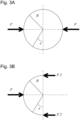
- ⁇ is an angle of a position at which the displacement w is considered with respect to a reference direction.
- one of the directions perpendicular to a direction in which the weight is applied is assumed to be the above-described reference direction, and ⁇ is determined thereby.
- a pipe rigidity which is the rigidity of the pipe, is defined by transforming the expression (2) and expressing the expression (2) in a form of the Hooke's law.
- a pipe rigidity K is expressed as the following expression (3).
- the pipe rigidity K is determined by the elasticity modulus E of the pipe, the wall thickness t, and the radius R of the pipe.
- the radius R of the pipe can be generally known from a drawing and the like of the pipe.
- the elasticity modulus E and the wall thickness t of the pipe may change with deterioration of the pipe.
- the pipe rigidity variable estimating unit 120 estimates, as one example of the parameter relating to the rigidity of the pipe, either one or both of the elasticity modulus E of the pipe or/and a value of the wall thickness t of the pipe.
- the parameter acquired by the pipe rigidity variable estimating unit 120 may be appropriately determined according to a relation and the like used in the strength estimating unit 130 to be described later.
- the expression of the frequency response function model is expressed as H( ⁇
- E, t, and R included in the pipe rigidity variable ⁇ M indicate, as described above, the elasticity modulus, the wall thickness of the pipe, and the radius of the pipe, respectively.
- the radius R is acquired from a drawing of the pipe, a description of configuration information of the pipe, and the like.
- the elasticity modulus E and the wall thickness t are estimated by the pipe rigidity variable estimating unit 120.
- the accessory parameter ⁇ F m, k, and c respectively indicate an equivalent mass, an equivalent rigidity, and an equivalent damping coefficient when the accessory is modeled.
- Each parameter included in the accessory parameter ⁇ F is previously determined according to actual values of the accessories 302 to which the exciter 161 and the measuring instrument 162 are attached. Those values are acquired from, for example, a drawing of the pipe or a description of configuration information of the pipe, a result of an actual measurement, and the like.
- a frequency response function model with respect to an example illustrated in Fig. 4 in which a spring, a mass, and a damper are connected to a ring is assumed.
- a ring unit corresponds to the pipe 301 illustrated in Fig. 2
- accessories correspond to the accessories 302 illustrated in Fig. 2 .
- ⁇ M , ⁇ F ) of the frequency response function model with respect to the example is expressed by the following expressions (4) and (5).
- M, K, and C respectively indicate an equivalent mass, an equivalent rigidity, and an equivalent damping coefficient when the ring unit illustrated in Fig. 4 is represented by a simple model of the mass, the spring, and the damper.
- the pipe rigidity variable estimating unit 120 acquires an estimated value of the pipe rigidity variable by approximating the expression H( ⁇
- the pipe rigidity variable estimating unit 120 acquires the estimated value of the pipe rigidity variable by using the following expression (6), for example.
- ⁇ ⁇ M argmin ⁇ i N ⁇ H ⁇ i
- argmin indicates a set of arguments that minimizes the function given in the brackets.
- the pipe rigidity variable estimating unit 120 acquires the estimated value of the pipe rigidity variable in such a way that a sum of squares of an absolute value of the difference between H( ⁇
- the pipe rigidity variable estimating unit 120 acquires the estimated value of the pipe rigidity variable by using, for example, a nonlinear optimization method such as a Levenberg-Marquardt method.
- the strength estimating unit 130 estimates strength of the pipe, on the basis of a relation between the parameter estimated by the pipe rigidity variable estimating unit 120 and the strength of the pipe.
- the strength estimating unit 130 estimates, mainly as the strength of the pipe, tensile strength of the pipe.
- the tensile strength of the pipe may change with deterioration of the pipe. Specifically, a degree of deterioration of the pipe is estimated by acquiring the tensile strength of the pipe.
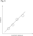
- the strength estimating unit 130 estimates the strength of the pipe by using, for example, a relation, as illustrated in Fig. 5 , between any one parameter relating to rigidity of the pipe and strength of the pipe, or a strength estimation equation generated from the relation illustrated in Fig. 5.
- Fig. 5 is an example illustrating a relation between an elasticity modulus, which is one of parameters relating to the rigidity of the pipe, and strength of the pipe.
- the strength estimating unit 130 estimates the strength of the pipe according to the parameter by applying some or all of the parameters estimated by the pipe rigidity variable estimating unit 120 to the above-described relation.
- the relation illustrated in Fig. 5 is acquired by, as one example, previously conducting an actual measurement by using a sample pipe. However, as the relation, a relation acquired by another means may be used. Further, the relation between the parameter relating to the rigidity of the pipe and the strength of the pipe is, for example, previously stored in the strength information storing unit 152.
- the strength estimating unit 130 refers to, as one of operation examples, being previously stored in the strength information storing unit 152, as appropriate, and estimates the strength of the pipe. Further, when a relation between any one of the parameters estimated by the pipe rigidity variable estimating unit 120 and strength of the pipe is acquired similarly to the relation and a relational expression illustrated in Fig. 5 , strength other than tensile strength may be acquired by the strength estimating unit 130. In this case, the strength estimating unit 130 acquires, for example, bending strength, compression strength, or yield stress.
- the tensile strength which is one of the strengths acquired by the strength estimating unit 130, is related to deterioration of the pipe. Specifically, the tensile strength indicates a degree of deterioration of the pipe. Therefore, the degree of deterioration of the pipe can be estimated by estimating the tensile strength.
- Step S101 excitation of the pipe, and measurement of a vibration response of the pipe and the fluid inside the pipe to the excitation are performed.
- the exciter 161 excites the accessory 302-1. Thereby, an elastic wave is excited in a fluid inside the pipe 301, and the pipe 301. Further, the measuring instrument 162 measures, via the accessory 302-2, vibration including the elastic wave generated by the excitation by the exciter 161. Thereby, data representing an excitation force and a vibration response are acquired. The data representing the excitation force and the vibration response acquired in Step S101 are sent to the frequency response calculating unit 110 via a communication network or another means.
- the frequency response calculating unit 110 acquires a frequency response function of the pipe, on the basis of the excitation force and the vibration response acquired in Step S101, (Step S102).
- the pipe rigidity variable estimating unit 120 estimates a parameter, on the basis of the frequency response function model in which a frequency response of the pipe is modeled and the frequency response function of the pipe acquired in Step S102 (Step S103). As described above, the pipe rigidity variable estimating unit 120 estimates, as one example, the elasticity modulus E and the wall thickness t of the pipe, which are values each included in the pipe rigidity variable ⁇ M .
- the strength estimating unit 130 estimates strength of the pipe, on the basis of the parameter relating to rigidity of the pipe acquired in Step S103, and a relation between the parameter and the strength of the pipe (Step S104).
- a relation stored in the strength information storing unit 152 is used as the relation between the parameter and the strength of the pipe.
- tensile strength of the pipe is estimated as the strength of the pipe.
- the acquired strength of the pipe is output via any means including a display and a communication network, as appropriate.
- the estimating device 100 estimates the parameter relating to the rigidity of the pipe, on the basis of the frequency response function model representing the frequency response of the pipe, and the frequency response function calculated on the basis of an actually measured value. Then, the estimating device 100 according to the present example embodiment estimates the strength of the pipe including the tensile strength, on the basis of the relation between the estimated parameter and the strength of the pipe.
- Fig. 7 is a measurement example of a response time waveform measured in a water-filled pipe filled with water inside the pipe.
- the response time waveform illustrated in Fig. 7 is one of actual examples of response data.
- Fig. 8 is a response spectrum with respect to the response time waveform illustrated in Fig. 7 .
- the response time waveform and its response spectrum illustrated in Figs. 7 and 8 are examples of a case where a measurement is performed when a distance between the accessory on which the exciter 161 is installed and the accessory on which the measuring instrument 162 is installed is about 100 m (meters).
- a resonance peak which is a frequency component at which acceleration increases, appears in a domain of approximately 500 Hz (Hertz) or less.
- the resonance peak is single.
- an interval at which accessories are installed is often several tens of meters or more. Therefore, a high frequency component of an elastic wave excited by the exciter 161 and propagating through a fluid inside the pipe and the pipe is attenuated before being measured by the measuring instrument 162.
- frequency of the resonance peak may be 500 Hz or less.
- an interval between a striking unit and a vibration receiving unit is assumed to be about several meters at most.
- a frequency domain of 0.5 kHz (kilohertz) to 7.0 kHz is assumed to be an entire frequency domain, and a frequency domain of 3.5 kHz to 7.0 kHz is assumed to be a high frequency domain. Then, strength of a pipe is estimated on the basis of an area ratio of the high frequency domain to the entire frequency domain.
- the pipe rigidity variable ⁇ M described above is acquired by using the frequency response function model according to a generation mechanism of a resonance peak in the response spectrum with respect to the response data.
- a parameter relating to the rigidity of the pipe is acquired by using an appropriate frequency response function model. Since the parameter relating to the rigidity of the pipe is acquired, strength of the pipe such as tensile strength is estimated in the estimating device 100. Specifically, the estimating device 100 according to the present example embodiment can estimate the strength of the water-filled pipe with ease.
Landscapes
- Physics & Mathematics (AREA)
- General Physics & Mathematics (AREA)
- Aviation & Aerospace Engineering (AREA)
- Engineering & Computer Science (AREA)
- General Health & Medical Sciences (AREA)
- Biochemistry (AREA)
- Analytical Chemistry (AREA)
- Chemical & Material Sciences (AREA)
- Immunology (AREA)
- Pathology (AREA)
- Life Sciences & Earth Sciences (AREA)
- Health & Medical Sciences (AREA)
- Testing Of Devices, Machine Parts, Or Other Structures Thereof (AREA)
- Measurement Of Mechanical Vibrations Or Ultrasonic Waves (AREA)
- Investigating Or Analyzing Materials By The Use Of Ultrasonic Waves (AREA)
Claims (7)
- Schätzvorrichtung, umfassend:eine Frequenzantwort-Berechnungseinrichtung (110) zum Berechnen, basierend auf einer Anregungskraft, wenn ein Rohr angeregt wird, und einer Schwingungsantwort, einer Frequenzantwortfunktion des Rohrs durch Ausführen einer Fourier-Transformation an der Anregungskraft und der Schwingungsantwort, wobei die Schwingungsantwort durch Messen einer sich durch das Rohr durch die Anregungskraft ausbreitenden elastischen Welle erlangt wird,eine Rohrsteifigkeitsvariablen-Schätzeinrichtung (120) zum Erlangen, basierend auf i) der berechneten Frequenzantwortfunktion und ii) einem Frequenzantwortfunktionsmodell, das eine Frequenzantwort des Rohrs darstellt und als Funktion einer Steifigkeitsvariablen des Rohrs ausgedrückt wird, eines geschätzten Werts der Steifigkeitsvariablen, wobei die Steifigkeitsvariable ein Parameter bezüglich einer Steifigkeit des Rohrs ist; undeine Festigkeits-Schätzeinrichtung (130) zum Schätzen, basierend auf einer Beziehung zwischen dem geschätzten Wert der Steifigkeitsvariablen und einer Festigkeit des Rohrs, der Festigkeit des Rohrs,wobei die Rohrsteifigkeitsvariablen-Schätzeinrichtung (120) konfiguriert ist, um den geschätzten Wert der Steifigkeitsvariablen durch Approximieren des Frequenzantwortfunktionsmodell an die Frequenzantwortfunktion zu erlangen.
- Schätzvorrichtung nach Anspruch 1, wobei
die Rohrsteifigkeitsvariablen-Schätzeinrichtung (120) den geschätzten Wert der Steifigkeitsvariablen auf solche Weise erlangt, dass eine Differenz zwischen dem Frequenzantwortfunktionsmodell und der Frequenzantwortfunktion innerhalb eines vorbestimmten Bereichs ist. - Schätzvorrichtung nach Anspruch 1 oder 2, wobei
der Parameter wenigstens entweder eines von einem Elastizitätsmodul des Rohrs oder einer Wanddicke des Rohrs ist. - Schätzvorrichtung nach einem der Ansprüche 1 bis 3, wobei
die Festigkeits-Schätzeinrichtung (130) als die Festigkeit die Zugfestigkeit schätzt. - Schätzvorrichtung nach einem der Ansprüche 1 bis 4, wobei
die Beziehung eine Beziehung zwischen einem Elastizitätsmodul und einer Zugfestigkeit des Rohrs ist. - Computerimplementiertes Schätzverfahren, umfassend:Berechnen, basierend auf einer Anregungskraft, wenn ein Rohr angeregt wird, und einer Schwingungsantwort, einer Frequenzantwortfunktion des Rohrs durch Ausführen einer Fourier-Transformation an der Anregungskraft und der Schwingungsantwort, wobei die Schwingungsantwort durch Messen einer sich durch das Rohr durch die Anregungskraft ausbreitenden elastischen Welle erlangt wird,Erlangen, basierend auf i) der berechneten Frequenzantwortfunktion und ii) einem Frequenzantwortfunktionsmodell, das eine Frequenzantwort des Rohrs darstellt und als Funktion einer Steifigkeitsvariablen des Rohrs ausgedrückt wird, eines geschätzten Werts der Steifigkeitsvariablen, wobei die Steifigkeitsvariable ein Parameter bezüglich einer Steifigkeit des Rohrs ist; undSchätzen, basierend auf einer Beziehung zwischen dem geschätzten Wert der Steifigkeitsvariablen und einer Festigkeit des Rohrs, der Festigkeit des Rohrs,wobei der geschätzte Wert der Steifigkeitsvariablen durch Approximieren des Frequenzantwortfunktionsmodell an die Frequenzantwortfunktion erlangt wird.
- Computerprogramm, das veranlasst, dass ein Computer das Verfahren nach Anspruch 6 ausführt.
Applications Claiming Priority (2)
| Application Number | Priority Date | Filing Date | Title |
|---|---|---|---|
| JP2017215729 | 2017-11-08 | ||
| PCT/JP2018/041089 WO2019093294A1 (ja) | 2017-11-08 | 2018-11-06 | 推定装置、推定方法及びプログラム記憶媒体 |
Publications (3)
| Publication Number | Publication Date |
|---|---|
| EP3708992A1 EP3708992A1 (de) | 2020-09-16 |
| EP3708992A4 EP3708992A4 (de) | 2020-12-23 |
| EP3708992B1 true EP3708992B1 (de) | 2024-10-16 |
Family
ID=66438812
Family Applications (1)
| Application Number | Title | Priority Date | Filing Date |
|---|---|---|---|
| EP18875039.2A Active EP3708992B1 (de) | 2017-11-08 | 2018-11-06 | Schätzvorrichtung, schätzverfahren und programmspeichermedium |
Country Status (4)
| Country | Link |
|---|---|
| US (1) | US20210181057A1 (de) |
| EP (1) | EP3708992B1 (de) |
| JP (1) | JP7004005B2 (de) |
| WO (1) | WO2019093294A1 (de) |
Families Citing this family (4)
| Publication number | Priority date | Publication date | Assignee | Title |
|---|---|---|---|---|
| JP7601041B2 (ja) * | 2022-03-24 | 2024-12-17 | 横河電機株式会社 | 診断装置、診断方法および診断プログラム |
| KR102579510B1 (ko) * | 2023-02-03 | 2023-09-18 | 주식회사 이솔구조건축사사무소 | 임팩트해머 시험에 의한 콘크리트의 강도 추정 시스템 |
| KR102590539B1 (ko) * | 2023-02-06 | 2023-10-17 | 주식회사 이솔구조건축사사무소 | 구조부재의 물성치 추정을 위한 비파괴 시험 방법 |
| CN119715797B (zh) * | 2025-02-26 | 2025-08-01 | 湖南安广检验检测有限公司 | 一种pe燃气管道抗拉性能的快速检测方法 |
Family Cites Families (8)
| Publication number | Priority date | Publication date | Assignee | Title |
|---|---|---|---|---|
| JPS61193067A (ja) * | 1985-02-21 | 1986-08-27 | Nippon Telegr & Teleph Corp <Ntt> | 鋳鉄品の評価方法及び装置 |
| JP3599882B2 (ja) * | 1996-03-25 | 2004-12-08 | いすゞ自動車株式会社 | 振動特性解析装置 |
| US7328618B2 (en) * | 2005-06-21 | 2008-02-12 | National Research Council Of Canada | Non-destructive testing of pipes |
| JP2007147634A (ja) * | 2006-12-22 | 2007-06-14 | Rikogaku Shinkokai | 振動解析の方法および装置ならびにコンピュータ読み取り可能な記録媒体 |
| JP5735369B2 (ja) | 2010-07-21 | 2015-06-17 | 積水化学工業株式会社 | 埋設管の検査方法および更生工法 |
| US20180045687A1 (en) * | 2015-03-24 | 2018-02-15 | Nec Corporation | Defect analysis device, defect analysis system, defect analysis method, and computer readable recording medium |
| WO2016194331A1 (ja) * | 2015-05-29 | 2016-12-08 | 日本電気株式会社 | 劣化分析装置、劣化分析方法および劣化分析プログラムおよび記録媒体 |
| JP6180587B1 (ja) | 2016-05-31 | 2017-08-16 | 株式会社セルシス | 2つの画像を対応づける方法、及びプログラム |
-
2018
- 2018-11-06 JP JP2019552789A patent/JP7004005B2/ja active Active
- 2018-11-06 US US16/761,336 patent/US20210181057A1/en not_active Abandoned
- 2018-11-06 EP EP18875039.2A patent/EP3708992B1/de active Active
- 2018-11-06 WO PCT/JP2018/041089 patent/WO2019093294A1/ja not_active Ceased
Also Published As
| Publication number | Publication date |
|---|---|
| EP3708992A4 (de) | 2020-12-23 |
| JPWO2019093294A1 (ja) | 2020-11-19 |
| WO2019093294A1 (ja) | 2019-05-16 |
| JP7004005B2 (ja) | 2022-01-21 |
| EP3708992A1 (de) | 2020-09-16 |
| US20210181057A1 (en) | 2021-06-17 |
Similar Documents
| Publication | Publication Date | Title |
|---|---|---|
| EP3708992A1 (de) | Schätzvorrichtung, schätzverfahren und programmspeichermedium | |
| US20190064030A1 (en) | Method Of Determining Stress Variations Over Time In An Undersea Pipe For Transporting Fluids | |
| CN103049670B (zh) | 管道激励源识别及其振动响应预测方法 | |
| US11454354B2 (en) | Pipe diagnosis apparatus, asset management apparatus, pipe diagnosis method, and computer-readable recording medium | |
| US20150176237A1 (en) | Riser Fatigue Monitoring | |
| US11455445B2 (en) | Method and system for non-intrusively inspecting a fluidic channel | |
| EP3764074B1 (de) | Rohrleitungsdiagnosevorrichtung, anlagenverwaltungsvorrichtung, rohrleitungsdiagnoseverfahren und aufzeichnungsmedium | |
| EP4658996A1 (de) | Multisensorverfahren und system zur charakterisierung einer rohrleitung | |
| JP7078060B2 (ja) | 分析装置および診断システム | |
| JP2004069598A (ja) | 構造物の損傷推定システムおよびプログラム | |
| US20190137044A1 (en) | Leakage position analyzing system, leakage position analyzing method, leakage position analyzing device, and computer-readable recording medium | |
| US20200049595A1 (en) | Pipe diagnosis apparatus, asset management apparatus, pipe diagnosis method, and computer-readable recording medium | |
| Galvagni | Pipeline health monitoring | |
| CN102914426A (zh) | 波纹管隔振性能试验装置及试验方法 | |
| US11249009B2 (en) | Diagnostic device, diagnostic system, diagnostic method, and computer-readable recording medium | |
| JP5390447B2 (ja) | 騒音対策効果量の推計方法 | |
| KR101931686B1 (ko) | 배관의 감육상태 감시 시스템 및 그 방법 | |
| KR101415359B1 (ko) | 배관의 원주방향 두께 추정 시스템 및 방법 | |
| WO2018159744A1 (ja) | 計測時間特定装置、検知装置、計測時間特定方法及びコンピュータ読み取り可能記録媒体 | |
| US20170322104A1 (en) | Position determination device, position determination system, position determination method, and computer-readable recording medium | |
| KR101890718B1 (ko) | 배관의 노화 상태 감시 방법 | |
| Kocsis | Modeling and vibration analysis of limescale deposition in geothermal pipes | |
| US11162867B2 (en) | Leak detection in viscoelastic pipes by matched-field processing method | |
| Hussels et al. | AGIFAMOR—Application of distributed acoustic and fibre optic sensors for continuous monitoring of pipes | |
| JP2017173101A (ja) | 診断装置、診断システム、診断方法及びプログラム |
Legal Events
| Date | Code | Title | Description |
|---|---|---|---|
| STAA | Information on the status of an ep patent application or granted ep patent |
Free format text: STATUS: THE INTERNATIONAL PUBLICATION HAS BEEN MADE |
|
| PUAI | Public reference made under article 153(3) epc to a published international application that has entered the european phase |
Free format text: ORIGINAL CODE: 0009012 |
|
| STAA | Information on the status of an ep patent application or granted ep patent |
Free format text: STATUS: REQUEST FOR EXAMINATION WAS MADE |
|
| 17P | Request for examination filed |
Effective date: 20200608 |
|
| AK | Designated contracting states |
Kind code of ref document: A1 Designated state(s): AL AT BE BG CH CY CZ DE DK EE ES FI FR GB GR HR HU IE IS IT LI LT LU LV MC MK MT NL NO PL PT RO RS SE SI SK SM TR |
|
| AX | Request for extension of the european patent |
Extension state: BA ME |
|
| A4 | Supplementary search report drawn up and despatched |
Effective date: 20201120 |
|
| RIC1 | Information provided on ipc code assigned before grant |
Ipc: G01M 7/08 20060101AFI20201116BHEP |
|
| DAV | Request for validation of the european patent (deleted) | ||
| DAX | Request for extension of the european patent (deleted) | ||
| STAA | Information on the status of an ep patent application or granted ep patent |
Free format text: STATUS: EXAMINATION IS IN PROGRESS |
|
| 17Q | First examination report despatched |
Effective date: 20220420 |
|
| GRAP | Despatch of communication of intention to grant a patent |
Free format text: ORIGINAL CODE: EPIDOSNIGR1 |
|
| STAA | Information on the status of an ep patent application or granted ep patent |
Free format text: STATUS: GRANT OF PATENT IS INTENDED |
|
| INTG | Intention to grant announced |
Effective date: 20240513 |
|
| GRAS | Grant fee paid |
Free format text: ORIGINAL CODE: EPIDOSNIGR3 |
|
| GRAA | (expected) grant |
Free format text: ORIGINAL CODE: 0009210 |
|
| STAA | Information on the status of an ep patent application or granted ep patent |
Free format text: STATUS: THE PATENT HAS BEEN GRANTED |
|
| AK | Designated contracting states |
Kind code of ref document: B1 Designated state(s): AL AT BE BG CH CY CZ DE DK EE ES FI FR GB GR HR HU IE IS IT LI LT LU LV MC MK MT NL NO PL PT RO RS SE SI SK SM TR |
|
| REG | Reference to a national code |
Ref country code: GB Ref legal event code: FG4D |
|
| REG | Reference to a national code |
Ref country code: CH Ref legal event code: EP |
|
| REG | Reference to a national code |
Ref country code: IE Ref legal event code: FG4D |
|
| REG | Reference to a national code |
Ref country code: DE Ref legal event code: R096 Ref document number: 602018075610 Country of ref document: DE |
|
| REG | Reference to a national code |
Ref country code: LT Ref legal event code: MG9D |
|
| REG | Reference to a national code |
Ref country code: NL Ref legal event code: MP Effective date: 20241016 |
|
| REG | Reference to a national code |
Ref country code: AT Ref legal event code: MK05 Ref document number: 1733270 Country of ref document: AT Kind code of ref document: T Effective date: 20241016 |
|
| PG25 | Lapsed in a contracting state [announced via postgrant information from national office to epo] |
Ref country code: NL Free format text: LAPSE BECAUSE OF FAILURE TO SUBMIT A TRANSLATION OF THE DESCRIPTION OR TO PAY THE FEE WITHIN THE PRESCRIBED TIME-LIMIT Effective date: 20241016 |
|
| PG25 | Lapsed in a contracting state [announced via postgrant information from national office to epo] |
Ref country code: NL Free format text: LAPSE BECAUSE OF FAILURE TO SUBMIT A TRANSLATION OF THE DESCRIPTION OR TO PAY THE FEE WITHIN THE PRESCRIBED TIME-LIMIT Effective date: 20241016 |
|
| PG25 | Lapsed in a contracting state [announced via postgrant information from national office to epo] |
Ref country code: IS Free format text: LAPSE BECAUSE OF FAILURE TO SUBMIT A TRANSLATION OF THE DESCRIPTION OR TO PAY THE FEE WITHIN THE PRESCRIBED TIME-LIMIT Effective date: 20250216 Ref country code: PT Free format text: LAPSE BECAUSE OF FAILURE TO SUBMIT A TRANSLATION OF THE DESCRIPTION OR TO PAY THE FEE WITHIN THE PRESCRIBED TIME-LIMIT Effective date: 20250217 Ref country code: HR Free format text: LAPSE BECAUSE OF FAILURE TO SUBMIT A TRANSLATION OF THE DESCRIPTION OR TO PAY THE FEE WITHIN THE PRESCRIBED TIME-LIMIT Effective date: 20241016 |
|
| PG25 | Lapsed in a contracting state [announced via postgrant information from national office to epo] |
Ref country code: FI Free format text: LAPSE BECAUSE OF FAILURE TO SUBMIT A TRANSLATION OF THE DESCRIPTION OR TO PAY THE FEE WITHIN THE PRESCRIBED TIME-LIMIT Effective date: 20241016 |
|
| PG25 | Lapsed in a contracting state [announced via postgrant information from national office to epo] |
Ref country code: BG Free format text: LAPSE BECAUSE OF FAILURE TO SUBMIT A TRANSLATION OF THE DESCRIPTION OR TO PAY THE FEE WITHIN THE PRESCRIBED TIME-LIMIT Effective date: 20241016 |
|
| PG25 | Lapsed in a contracting state [announced via postgrant information from national office to epo] |
Ref country code: ES Free format text: LAPSE BECAUSE OF FAILURE TO SUBMIT A TRANSLATION OF THE DESCRIPTION OR TO PAY THE FEE WITHIN THE PRESCRIBED TIME-LIMIT Effective date: 20241016 |
|
| PG25 | Lapsed in a contracting state [announced via postgrant information from national office to epo] |
Ref country code: NO Free format text: LAPSE BECAUSE OF FAILURE TO SUBMIT A TRANSLATION OF THE DESCRIPTION OR TO PAY THE FEE WITHIN THE PRESCRIBED TIME-LIMIT Effective date: 20250116 |
|
| PG25 | Lapsed in a contracting state [announced via postgrant information from national office to epo] |
Ref country code: AT Free format text: LAPSE BECAUSE OF FAILURE TO SUBMIT A TRANSLATION OF THE DESCRIPTION OR TO PAY THE FEE WITHIN THE PRESCRIBED TIME-LIMIT Effective date: 20241016 Ref country code: GR Free format text: LAPSE BECAUSE OF FAILURE TO SUBMIT A TRANSLATION OF THE DESCRIPTION OR TO PAY THE FEE WITHIN THE PRESCRIBED TIME-LIMIT Effective date: 20250117 Ref country code: LV Free format text: LAPSE BECAUSE OF FAILURE TO SUBMIT A TRANSLATION OF THE DESCRIPTION OR TO PAY THE FEE WITHIN THE PRESCRIBED TIME-LIMIT Effective date: 20241016 |
|
| PG25 | Lapsed in a contracting state [announced via postgrant information from national office to epo] |
Ref country code: PL Free format text: LAPSE BECAUSE OF FAILURE TO SUBMIT A TRANSLATION OF THE DESCRIPTION OR TO PAY THE FEE WITHIN THE PRESCRIBED TIME-LIMIT Effective date: 20241016 |
|
| PG25 | Lapsed in a contracting state [announced via postgrant information from national office to epo] |
Ref country code: RS Free format text: LAPSE BECAUSE OF FAILURE TO SUBMIT A TRANSLATION OF THE DESCRIPTION OR TO PAY THE FEE WITHIN THE PRESCRIBED TIME-LIMIT Effective date: 20250116 |
|
| REG | Reference to a national code |
Ref country code: DE Ref legal event code: R119 Ref document number: 602018075610 Country of ref document: DE |
|
| REG | Reference to a national code |
Ref country code: CH Ref legal event code: PL |
|
| PG25 | Lapsed in a contracting state [announced via postgrant information from national office to epo] |
Ref country code: SM Free format text: LAPSE BECAUSE OF FAILURE TO SUBMIT A TRANSLATION OF THE DESCRIPTION OR TO PAY THE FEE WITHIN THE PRESCRIBED TIME-LIMIT Effective date: 20241016 |
|
| PG25 | Lapsed in a contracting state [announced via postgrant information from national office to epo] |
Ref country code: MC Free format text: LAPSE BECAUSE OF FAILURE TO SUBMIT A TRANSLATION OF THE DESCRIPTION OR TO PAY THE FEE WITHIN THE PRESCRIBED TIME-LIMIT Effective date: 20241016 |
|
| PG25 | Lapsed in a contracting state [announced via postgrant information from national office to epo] |
Ref country code: DK Free format text: LAPSE BECAUSE OF FAILURE TO SUBMIT A TRANSLATION OF THE DESCRIPTION OR TO PAY THE FEE WITHIN THE PRESCRIBED TIME-LIMIT Effective date: 20241016 |
|
| PG25 | Lapsed in a contracting state [announced via postgrant information from national office to epo] |
Ref country code: LU Free format text: LAPSE BECAUSE OF NON-PAYMENT OF DUE FEES Effective date: 20241106 |
|
| REG | Reference to a national code |
Ref country code: CH Ref legal event code: PL |
|
| PG25 | Lapsed in a contracting state [announced via postgrant information from national office to epo] |
Ref country code: EE Free format text: LAPSE BECAUSE OF FAILURE TO SUBMIT A TRANSLATION OF THE DESCRIPTION OR TO PAY THE FEE WITHIN THE PRESCRIBED TIME-LIMIT Effective date: 20241016 |
|
| PG25 | Lapsed in a contracting state [announced via postgrant information from national office to epo] |
Ref country code: CH Free format text: LAPSE BECAUSE OF NON-PAYMENT OF DUE FEES Effective date: 20241130 |
|
| PG25 | Lapsed in a contracting state [announced via postgrant information from national office to epo] |
Ref country code: RO Free format text: LAPSE BECAUSE OF FAILURE TO SUBMIT A TRANSLATION OF THE DESCRIPTION OR TO PAY THE FEE WITHIN THE PRESCRIBED TIME-LIMIT Effective date: 20241016 |
|
| PG25 | Lapsed in a contracting state [announced via postgrant information from national office to epo] |
Ref country code: SK Free format text: LAPSE BECAUSE OF FAILURE TO SUBMIT A TRANSLATION OF THE DESCRIPTION OR TO PAY THE FEE WITHIN THE PRESCRIBED TIME-LIMIT Effective date: 20241016 |
|
| PG25 | Lapsed in a contracting state [announced via postgrant information from national office to epo] |
Ref country code: CZ Free format text: LAPSE BECAUSE OF FAILURE TO SUBMIT A TRANSLATION OF THE DESCRIPTION OR TO PAY THE FEE WITHIN THE PRESCRIBED TIME-LIMIT Effective date: 20241016 |
|
| PG25 | Lapsed in a contracting state [announced via postgrant information from national office to epo] |
Ref country code: IT Free format text: LAPSE BECAUSE OF FAILURE TO SUBMIT A TRANSLATION OF THE DESCRIPTION OR TO PAY THE FEE WITHIN THE PRESCRIBED TIME-LIMIT Effective date: 20241016 |
|
| PLBE | No opposition filed within time limit |
Free format text: ORIGINAL CODE: 0009261 |
|
| STAA | Information on the status of an ep patent application or granted ep patent |
Free format text: STATUS: NO OPPOSITION FILED WITHIN TIME LIMIT |
|
| REG | Reference to a national code |
Ref country code: BE Ref legal event code: MM Effective date: 20241130 |
|
| PG25 | Lapsed in a contracting state [announced via postgrant information from national office to epo] |
Ref country code: SE Free format text: LAPSE BECAUSE OF FAILURE TO SUBMIT A TRANSLATION OF THE DESCRIPTION OR TO PAY THE FEE WITHIN THE PRESCRIBED TIME-LIMIT Effective date: 20241016 |
|
| 26N | No opposition filed |
Effective date: 20250717 |
|
| PG25 | Lapsed in a contracting state [announced via postgrant information from national office to epo] |
Ref country code: DE Free format text: LAPSE BECAUSE OF NON-PAYMENT OF DUE FEES Effective date: 20250603 |
|
| PG25 | Lapsed in a contracting state [announced via postgrant information from national office to epo] |
Ref country code: BE Free format text: LAPSE BECAUSE OF NON-PAYMENT OF DUE FEES Effective date: 20241130 |
|
| PG25 | Lapsed in a contracting state [announced via postgrant information from national office to epo] |
Ref country code: FR Free format text: LAPSE BECAUSE OF NON-PAYMENT OF DUE FEES Effective date: 20241216 |
|
| PG25 | Lapsed in a contracting state [announced via postgrant information from national office to epo] |
Ref country code: IE Free format text: LAPSE BECAUSE OF NON-PAYMENT OF DUE FEES Effective date: 20241106 |
|
| PGFP | Annual fee paid to national office [announced via postgrant information from national office to epo] |
Ref country code: GB Payment date: 20251121 Year of fee payment: 8 |
|
| PG25 | Lapsed in a contracting state [announced via postgrant information from national office to epo] |
Ref country code: HU Free format text: LAPSE BECAUSE OF FAILURE TO SUBMIT A TRANSLATION OF THE DESCRIPTION OR TO PAY THE FEE WITHIN THE PRESCRIBED TIME-LIMIT; INVALID AB INITIO Effective date: 20181106 |
|
| PG25 | Lapsed in a contracting state [announced via postgrant information from national office to epo] |
Ref country code: CY Free format text: LAPSE BECAUSE OF FAILURE TO SUBMIT A TRANSLATION OF THE DESCRIPTION OR TO PAY THE FEE WITHIN THE PRESCRIBED TIME-LIMIT; INVALID AB INITIO Effective date: 20181106 |