EP3708905B1 - Lighting device imaging the mirrored image of a light collector - Google Patents
Lighting device imaging the mirrored image of a light collector Download PDFInfo
- Publication number
- EP3708905B1 EP3708905B1 EP20158866.2A EP20158866A EP3708905B1 EP 3708905 B1 EP3708905 B1 EP 3708905B1 EP 20158866 A EP20158866 A EP 20158866A EP 3708905 B1 EP3708905 B1 EP 3708905B1
- Authority
- EP
- European Patent Office
- Prior art keywords
- collector
- light source
- optical axis
- light
- reflective surface
- Prior art date
- Legal status (The legal status is an assumption and is not a legal conclusion. Google has not performed a legal analysis and makes no representation as to the accuracy of the status listed.)
- Active
Links
- 238000003384 imaging method Methods 0.000 title description 4
- 230000003287 optical effect Effects 0.000 claims description 83
- 239000000758 substrate Substances 0.000 claims description 7
- 230000006870 function Effects 0.000 description 5
- 238000005286 illumination Methods 0.000 description 5
- 230000009131 signaling function Effects 0.000 description 3
- 239000004697 Polyetherimide Substances 0.000 description 2
- 239000004417 polycarbonate Substances 0.000 description 2
- 229920001601 polyetherimide Polymers 0.000 description 2
- 230000011664 signaling Effects 0.000 description 2
- 230000004075 alteration Effects 0.000 description 1
- 230000007547 defect Effects 0.000 description 1
- 238000005401 electroluminescence Methods 0.000 description 1
- 230000005670 electromagnetic radiation Effects 0.000 description 1
- 239000011521 glass Substances 0.000 description 1
- 238000004519 manufacturing process Methods 0.000 description 1
- 239000000463 material Substances 0.000 description 1
- 238000000034 method Methods 0.000 description 1
- 239000012994 photoredox catalyst Substances 0.000 description 1
- 229920000515 polycarbonate Polymers 0.000 description 1
- 230000001105 regulatory effect Effects 0.000 description 1
- 239000004065 semiconductor Substances 0.000 description 1
- 229920001059 synthetic polymer Polymers 0.000 description 1
- 230000007306 turnover Effects 0.000 description 1
Images

Classifications
-
- F—MECHANICAL ENGINEERING; LIGHTING; HEATING; WEAPONS; BLASTING
- F21—LIGHTING
- F21S—NON-PORTABLE LIGHTING DEVICES; SYSTEMS THEREOF; VEHICLE LIGHTING DEVICES SPECIALLY ADAPTED FOR VEHICLE EXTERIORS
- F21S41/00—Illuminating devices specially adapted for vehicle exteriors, e.g. headlamps
- F21S41/30—Illuminating devices specially adapted for vehicle exteriors, e.g. headlamps characterised by reflectors
- F21S41/32—Optical layout thereof
-
- F—MECHANICAL ENGINEERING; LIGHTING; HEATING; WEAPONS; BLASTING
- F21—LIGHTING
- F21S—NON-PORTABLE LIGHTING DEVICES; SYSTEMS THEREOF; VEHICLE LIGHTING DEVICES SPECIALLY ADAPTED FOR VEHICLE EXTERIORS
- F21S41/00—Illuminating devices specially adapted for vehicle exteriors, e.g. headlamps
- F21S41/10—Illuminating devices specially adapted for vehicle exteriors, e.g. headlamps characterised by the light source
- F21S41/14—Illuminating devices specially adapted for vehicle exteriors, e.g. headlamps characterised by the light source characterised by the type of light source
- F21S41/141—Light emitting diodes [LED]
- F21S41/147—Light emitting diodes [LED] the main emission direction of the LED being angled to the optical axis of the illuminating device
-
- B—PERFORMING OPERATIONS; TRANSPORTING
- B60—VEHICLES IN GENERAL
- B60Q—ARRANGEMENT OF SIGNALLING OR LIGHTING DEVICES, THE MOUNTING OR SUPPORTING THEREOF OR CIRCUITS THEREFOR, FOR VEHICLES IN GENERAL
- B60Q1/00—Arrangement of optical signalling or lighting devices, the mounting or supporting thereof or circuits therefor
- B60Q1/02—Arrangement of optical signalling or lighting devices, the mounting or supporting thereof or circuits therefor the devices being primarily intended to illuminate the way ahead or to illuminate other areas of way or environments
- B60Q1/04—Arrangement of optical signalling or lighting devices, the mounting or supporting thereof or circuits therefor the devices being primarily intended to illuminate the way ahead or to illuminate other areas of way or environments the devices being headlights
- B60Q1/14—Arrangement of optical signalling or lighting devices, the mounting or supporting thereof or circuits therefor the devices being primarily intended to illuminate the way ahead or to illuminate other areas of way or environments the devices being headlights having dimming means
-
- F—MECHANICAL ENGINEERING; LIGHTING; HEATING; WEAPONS; BLASTING
- F21—LIGHTING
- F21S—NON-PORTABLE LIGHTING DEVICES; SYSTEMS THEREOF; VEHICLE LIGHTING DEVICES SPECIALLY ADAPTED FOR VEHICLE EXTERIORS
- F21S41/00—Illuminating devices specially adapted for vehicle exteriors, e.g. headlamps
- F21S41/10—Illuminating devices specially adapted for vehicle exteriors, e.g. headlamps characterised by the light source
- F21S41/14—Illuminating devices specially adapted for vehicle exteriors, e.g. headlamps characterised by the light source characterised by the type of light source
- F21S41/141—Light emitting diodes [LED]
- F21S41/147—Light emitting diodes [LED] the main emission direction of the LED being angled to the optical axis of the illuminating device
- F21S41/148—Light emitting diodes [LED] the main emission direction of the LED being angled to the optical axis of the illuminating device the main emission direction of the LED being perpendicular to the optical axis
-
- F—MECHANICAL ENGINEERING; LIGHTING; HEATING; WEAPONS; BLASTING
- F21—LIGHTING
- F21S—NON-PORTABLE LIGHTING DEVICES; SYSTEMS THEREOF; VEHICLE LIGHTING DEVICES SPECIALLY ADAPTED FOR VEHICLE EXTERIORS
- F21S41/00—Illuminating devices specially adapted for vehicle exteriors, e.g. headlamps
- F21S41/20—Illuminating devices specially adapted for vehicle exteriors, e.g. headlamps characterised by refractors, transparent cover plates, light guides or filters
- F21S41/25—Projection lenses
-
- F—MECHANICAL ENGINEERING; LIGHTING; HEATING; WEAPONS; BLASTING
- F21—LIGHTING
- F21S—NON-PORTABLE LIGHTING DEVICES; SYSTEMS THEREOF; VEHICLE LIGHTING DEVICES SPECIALLY ADAPTED FOR VEHICLE EXTERIORS
- F21S41/00—Illuminating devices specially adapted for vehicle exteriors, e.g. headlamps
- F21S41/30—Illuminating devices specially adapted for vehicle exteriors, e.g. headlamps characterised by reflectors
- F21S41/32—Optical layout thereof
- F21S41/321—Optical layout thereof the reflector being a surface of revolution or a planar surface, e.g. truncated
-
- F—MECHANICAL ENGINEERING; LIGHTING; HEATING; WEAPONS; BLASTING
- F21—LIGHTING
- F21S—NON-PORTABLE LIGHTING DEVICES; SYSTEMS THEREOF; VEHICLE LIGHTING DEVICES SPECIALLY ADAPTED FOR VEHICLE EXTERIORS
- F21S41/00—Illuminating devices specially adapted for vehicle exteriors, e.g. headlamps
- F21S41/30—Illuminating devices specially adapted for vehicle exteriors, e.g. headlamps characterised by reflectors
- F21S41/32—Optical layout thereof
- F21S41/33—Multi-surface reflectors, e.g. reflectors with facets or reflectors with portions of different curvature
- F21S41/338—Multi-surface reflectors, e.g. reflectors with facets or reflectors with portions of different curvature the reflector having surface portions added to its general concavity
-
- F—MECHANICAL ENGINEERING; LIGHTING; HEATING; WEAPONS; BLASTING
- F21—LIGHTING
- F21S—NON-PORTABLE LIGHTING DEVICES; SYSTEMS THEREOF; VEHICLE LIGHTING DEVICES SPECIALLY ADAPTED FOR VEHICLE EXTERIORS
- F21S41/00—Illuminating devices specially adapted for vehicle exteriors, e.g. headlamps
- F21S41/30—Illuminating devices specially adapted for vehicle exteriors, e.g. headlamps characterised by reflectors
- F21S41/32—Optical layout thereof
- F21S41/36—Combinations of two or more separate reflectors
- F21S41/365—Combinations of two or more separate reflectors successively reflecting the light
-
- F—MECHANICAL ENGINEERING; LIGHTING; HEATING; WEAPONS; BLASTING
- F21—LIGHTING
- F21S—NON-PORTABLE LIGHTING DEVICES; SYSTEMS THEREOF; VEHICLE LIGHTING DEVICES SPECIALLY ADAPTED FOR VEHICLE EXTERIORS
- F21S41/00—Illuminating devices specially adapted for vehicle exteriors, e.g. headlamps
- F21S41/60—Illuminating devices specially adapted for vehicle exteriors, e.g. headlamps characterised by a variable light distribution
-
- F—MECHANICAL ENGINEERING; LIGHTING; HEATING; WEAPONS; BLASTING
- F21—LIGHTING
- F21V—FUNCTIONAL FEATURES OR DETAILS OF LIGHTING DEVICES OR SYSTEMS THEREOF; STRUCTURAL COMBINATIONS OF LIGHTING DEVICES WITH OTHER ARTICLES, NOT OTHERWISE PROVIDED FOR
- F21V13/00—Producing particular characteristics or distribution of the light emitted by means of a combination of elements specified in two or more of main groups F21V1/00 - F21V11/00
- F21V13/02—Combinations of only two kinds of elements
- F21V13/04—Combinations of only two kinds of elements the elements being reflectors and refractors
-
- F—MECHANICAL ENGINEERING; LIGHTING; HEATING; WEAPONS; BLASTING
- F21—LIGHTING
- F21V—FUNCTIONAL FEATURES OR DETAILS OF LIGHTING DEVICES OR SYSTEMS THEREOF; STRUCTURAL COMBINATIONS OF LIGHTING DEVICES WITH OTHER ARTICLES, NOT OTHERWISE PROVIDED FOR
- F21V5/00—Refractors for light sources
- F21V5/04—Refractors for light sources of lens shape
-
- F—MECHANICAL ENGINEERING; LIGHTING; HEATING; WEAPONS; BLASTING
- F21—LIGHTING
- F21V—FUNCTIONAL FEATURES OR DETAILS OF LIGHTING DEVICES OR SYSTEMS THEREOF; STRUCTURAL COMBINATIONS OF LIGHTING DEVICES WITH OTHER ARTICLES, NOT OTHERWISE PROVIDED FOR
- F21V7/00—Reflectors for light sources
- F21V7/04—Optical design
-
- F—MECHANICAL ENGINEERING; LIGHTING; HEATING; WEAPONS; BLASTING
- F21—LIGHTING
- F21W—INDEXING SCHEME ASSOCIATED WITH SUBCLASSES F21K, F21L, F21S and F21V, RELATING TO USES OR APPLICATIONS OF LIGHTING DEVICES OR SYSTEMS
- F21W2102/00—Exterior vehicle lighting devices for illuminating purposes
-
- F—MECHANICAL ENGINEERING; LIGHTING; HEATING; WEAPONS; BLASTING
- F21—LIGHTING
- F21W—INDEXING SCHEME ASSOCIATED WITH SUBCLASSES F21K, F21L, F21S and F21V, RELATING TO USES OR APPLICATIONS OF LIGHTING DEVICES OR SYSTEMS
- F21W2107/00—Use or application of lighting devices on or in particular types of vehicles
- F21W2107/10—Use or application of lighting devices on or in particular types of vehicles for land vehicles
-
- F—MECHANICAL ENGINEERING; LIGHTING; HEATING; WEAPONS; BLASTING
- F21—LIGHTING
- F21Y—INDEXING SCHEME ASSOCIATED WITH SUBCLASSES F21K, F21L, F21S and F21V, RELATING TO THE FORM OR THE KIND OF THE LIGHT SOURCES OR OF THE COLOUR OF THE LIGHT EMITTED
- F21Y2115/00—Light-generating elements of semiconductor light sources
- F21Y2115/10—Light-emitting diodes [LED]
Definitions
- the invention relates to the field of lighting and light signaling, more particularly in the automotive field.
- the published patent document FR 3 047 541 A1 discloses a lighting device comprising two optical modules arranged oppositely. Each of these two optical modules essentially comprises a light source and a collector with a reflective surface. These two light sources are arranged on two opposite faces of a common support. Each of the reflecting surfaces is a surface of revolution in a half-space delimited by the common support of the light sources. The two reflective surfaces thus form two opposite half-shells.
- One of the two optical modules is configured to form an illumination beam with horizontal cut-off, corresponding to a so-called "code” beam (in English "low-beam”). To do this, the module comprises a reflective surface with a so-called “cutoff” edge located at a focal point of the reflective surface.
- Such a light device has the disadvantage of requiring high precision in the positioning of the folder and the cutting edge.
- the projection lens must be a thick lens due to its short focal length, which increases its weight and complicates its production, such as shrinkage defects in particular.
- the collector has a certain height and, therefore, a certain overall height.
- the object of the invention is to overcome at least one of the drawbacks of the aforementioned state of the art. More particularly, the object of the invention is to propose a luminous module or device for lighting and/or signaling which is compact and more economical to produce.
- the invention relates to a light device, in particular for a motor vehicle, comprising a light source capable of emitting light rays; a collector with a reflecting surface configured to collect and reflect the light rays emitted by the light source; an optical system configured to project the light rays coming from the reflecting surface into a light beam along an optical axis of the light device; remarkable in that the luminous device comprises a mirror configured to form a virtual image of the light source and of the reflective surface of the collector, and the optical system is configured to form an image of said virtual image.
- the light source and the reflective surface form a light module.
- a light module is able to form a light beam.
- the light device may comprise several light modules. In the presence of a single luminous module, the luminous device is comparable to the luminous module.
- the light device forms an autonomous assembly in that each of its components, such as for example the light source(s), the collector(s) and the optical system, is rigidly linked to the other components, in particular via a specific support (not detailed) , and is thus optically positioned relative to the other components.
- One or more lighting devices can thus be arranged in a headlamp housing in order to perform, where appropriate in combination, all the regulatory lighting and signaling functions.
- the reflective surface of the collector and the mirror are configured so that the light rays reflected by a rear part of said reflective surface are parallel to the optical axis or present, in a vertical plane and relative to said axis, an angle of inclination less than or equal to 25°, preferably less than or equal to 10°.
- the mirror is plane and parallel to the optical axis or is inclined with respect to said optical axis by an angle less than 10°.
- the light source is configured to emit the light rays in a main direction perpendicular to the optical axis or inclined with respect to a direction perpendicular to said optical axis by an angle less than 25°.
- the reflective surface of the collector has a parabolic or elliptical profile.
- it is a surface of revolution of said profile.
- the revolution is around an axis advantageously parallel to the optical axis.
- the reflecting surface is a free-form surface or a swept surface or an asymmetrical surface. It can also include several sectors.
- the mirror extends in an extension, towards the optical system, of the reflective surface of the collector.
- the reflective surface of the collector is configured to reflect the light rays emitted by the light source in a main direction divergent with the optical axis.
- the light source is arranged on a substrate, the mirror being aligned with said substrate.
- the reflective surface of the collector is configured to reflect the light rays emitted by the light source in a main direction converging with the optical axis, said optical axis passing through the substrate.
- the optical system has a focus located on a zone located between the virtual light source and the virtual reflecting surface.
- the focal point of the optical system is located on the virtual reflecting surface, at the rear of the virtual light source along the optical axis.
- the optical system comprises a lens corresponding to a converging lens portion centered on a virtual optical axis parallel to the optical axis and passing through the focal point of the optical system.
- the reflective surface of the collector has a rear edge, the light beam being a horizontal cut-off beam, said cut-off being an image of said rear edge.
- the light source and the collector are located above the optical axis when the light device is in the functional position, the cutoff of the light beam being a lower cutoff.
- the light source and the collector are located below the optical axis when the light device is in the functional position, the cutoff of the light beam being an upper cutoff.
- the light source, the collector and the light beam are a first light source, a first collector and a first light beam, respectively
- the light device comprising a second light source and a second collector with a reflective surface configured to collect and reflect the light rays emitted by the second light source, the optical system being configured to project the light rays coming from said reflective surface into a second light beam along an optical axis of the device and corresponding to an image of said reflective surface.
- the first collector and the first light source form a first light module and the second collector and the second light source form a second light module.
- the light device is configured so that the second light beam is a real image of the reflecting surface of the second collector illuminated by the second light source.
- the light rays reflected by the reflecting surface of the second collector are transmitted to the optical system without being reflected by a mirror, unlike the light rays reflected by the reflecting surface of the first collector.
- the first collector and the first light source are opposed, with respect to the optical axis, to the second collector and to the second light source, respectively; or the first collector and the first light source, on the one hand, and the second collector and the second light source, on the other hand, are arranged side by side.
- the measures of the invention are advantageous in that they make it possible to produce a compact luminous module or device, easy to assemble with a reduced number of parts and able to carry out various lighting and/or signaling functions. More particularly, the fact of imaging the illuminated reflective surface of the collector makes it possible to produce a light beam with a concentration of light at a vertically off-center position of said beam. Also, the invention makes it very easy to return the image produced and thus to modulate the light beam or beams to the lighting and/or signaling functions to be provided, in particular the "dipped" and "highway” lighting functions. .
- the notions of "above” and “below” the optical axis of the light device are to be understood when the light device is in the functional position, that is to say with a orientation corresponding to that for which it was designed.
- the notions “front” and “rear” are to be understood along the general direction of the light, along the optical axis, when the luminous device is in the functional position.
- the figures 1 to 4 illustrate a first embodiment of a light device according to the invention.
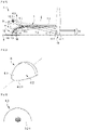
- the figure 1 is a schematic representation of the light device and its principle of operation.
- the light device 2 essentially comprises a light source 4, a collector 6 capable of reflecting the light rays emitted by the light source to form a first light beam 12 along an optical axis 8 of the device, and a projection lens 10 of said beam .
- other systems projection optics as the projection lens are possible, such as in particular one or more mirrors.
- the light source 4 is advantageously of the semiconductor type, such as in particular an electroluminescence diode.
- the light source 4 emits light rays in a half-space delimited by the main plane of said source, according to the example shown, in a main direction perpendicular to said plane and to the optical axis 8.
- the direction main emission may be inclined relative to a direction perpendicular to the optical axis by an angle less than or equal to 25°.
- the collector 6 comprises a support 6.1, in the form of a shell or cap, and a reflecting surface 6.2 on the inner face of the support 6.1.
- the reflective surface 6.2 is advantageously of the profile of the elliptical or parabolic or “free form” type.
- the luminous device 2 also comprises a mirror 7 arranged in the extension of the reflecting surface 6.2 of the collector 6.
- the mirror 7 comprises a support 7.1 and a flat reflecting surface 7.2 formed on the support 7.1. The latter can be confused with or adjacent to the support 6.1 of the collector.
- the reflective surface 6.2 of the collector 6 is advantageously a surface of revolution around an axis parallel to the optical axis 8.
- the expression "parabolic type” generally applies to reflectors whose surface has a single focal point, that is to say a zone of convergence of the light rays such that the light rays emitted by a light source placed at the level of this convergence zone are projected at a great distance after reflection on the surface. Projected at a great distance means that these light rays do not converge on an area located at least 10 times the dimensions of the reflector.
- the reflected rays do not converge towards a convergence zone or, if they do converge, this convergence zone is located at a distance greater than or equal to 10 times the dimensions of the reflector.
- a parabolic-type surface may therefore have parabolic portions or not.
- a reflector having such a surface is generally used alone to create a light beam. Alternatively it can be used as a projection surface associated with an elliptical-type reflector. In this case the light source of the parabolic type reflector is the convergence zone of the rays reflected by the elliptical type reflector.
- the mirror 7, more particularly its flat reflective surface 7.2 is advantageously parallel to the optical axis 8. It can however be inclined with respect to said axis, for example by an angle less than or equal to 10°. If it is tilted, the mirror is advantageously divergent with the optical axis in the main direction of propagation of the light, that is to say from the light source 4 towards the projection lens 10.
- the collector 6 in the form of a shell or cap is advantageously made of materials having good heat resistance, for example glass or synthetic polymers such as polycarbonate PC or polyetherimide PEI.
- the light source 4 is placed at a focal point of the reflective surface 6.2 of the collector 6 so that its rays are collected and reflected towards the mirror 7.
- the latter forms a virtual image 6.2 of the reflective surface 6.2 and a virtual image 4 of the light source 4, shown in broken line at the figure 1 .
- the optical system 10 projects a light image of the virtual image 6.2 of the reflecting surface 6.2 and the virtual image 4 of the light source 4.
- At least some of these rays reflected by the mirror 7 have angles of inclination ⁇ relative to said axis, in a vertical plane, which are less than or equal to 25°, preferably less than or equal to 10°, so as to be under the so-called Gaussian conditions, making it possible to obtain a stigma, that is ie sharpness of the projected image.
- angles of inclination ⁇ relative to said axis, in a vertical plane which are less than or equal to 25°, preferably less than or equal to 10°, so as to be under the so-called Gaussian conditions, making it possible to obtain a stigma, that is ie sharpness of the projected image.
- the projection lens 10 has a first entry face 10.1 and exit face 10.2.
- the lens 10 is said to be thin, for example with a thickness along the optical axis which is less than 7 mm, in particular because of the low height of the lens and its long focal length.
- the lens 10 may have a focal point 10.3 advantageously located between the virtual light source and the virtual reflecting surface.
- the focus 10.3 in question is advantageously located on a zone 6.3 located between the virtual images 6.2 and 4 of the reflecting surface 6.2 and of the light source 4.
- the focus can be located on the virtual image 6.2 of the reflective surface 6.2, axially (that is to say along the optical axis) behind the virtual image 4 of the virtual light source 4.
- this focus it is also possible for this focus to be located at behind or in front of the virtual image of the reflective surface 6.2 of the collector 6 provided that it is close, preferably less than 10 mm, preferably less than 5 mm.
- the lens 10 is advantageously of the symmetrical convergent type with respect to the virtual optical axis 8 (in dashed line) located above the optical axis 8 and advantageously passing through the focal point 10.3.
- the reflective surface 6.2 of the collector 6, if it is of the elliptical type, has a second focus located at the front of the lens 10 and at a distance from the optical axis 8. It should be noted that it is also possible that this focal point is located at the rear of the lens and/or on the optical axis, provided that it is close to the lens, so as to reduce the width of the beam at the level of the entrance face of the lens.
- the light source 4 and the collector 6 are advantageously a first light source and a first collector, the device then possibly comprising a second light source 14 and a second collector 16 (shown in dashed lines).
- the second light source 14 and the second collector 16, forming a second light module are opposite with respect to the optical axis 8 More particularly, the first and second light sources 4 and 14 are on opposite faces of a common substrate through which the optical axis 8 passes.
- the figure 2 is a rear view, in perspective, of a rear part of the collector 6 of the luminous device 2 of the figure 1 .
- the plane in question comprises the rear edge 6.2.1. This extends laterally in the plane on either side of the axis of revolution.
- the picture 3 is a representation of the light intensity at the reflective surface 6.2 of the collector seen from the outside, along the optical axis.
- This is the projected image of the virtual image of the reflective surface 6.2 of the collector, produced by the mirror 7 ( figure 1 ). More specifically, surface illuminance, ie the power of striking electromagnetic radiation per unit area perpendicular to its direction, expressed in W/m 2 .
- the dark zone covering the majority of the surface corresponds to weaker illuminations while the central, lighter zone corresponds to greater illuminations. It can be seen that the dark area is clearly delimited by the lower edge 6.2.1.
- the illuminated surface 6.2 naturally has a sharp lower edge capable of forming a cut in the projected lighting beam imaging this surface and also a light concentration force, in a central position at the height of the light source.
- the figure 4 is a graphic representation of the image projected by the light device of the figure 1 .
- the horizontal axis H and the vertical axis V intersect at the level of the optical axis of the light device.
- the curves are isolux, that is to say correspond to the zones of the light beam 12 which have the same illumination expressed in lux.
- the curves in the center correspond to a higher level of illumination than at the periphery.
- the light beam 12 has a lower horizontal cut-off, essentially at the level of the horizontal axis.
- the cut is not perfectly straight; it has a curvature which corresponds to aberrations of the image thus produced.
- the horizontal cut is made by the edge 6.2.1 ( picture 3 ) which is the trailing edge ( picture 2 ) of the reflective surface 6.2 of the collector 6.
- the focal point 10.3 of the lens 10 ( figure 1 ) is advantageously located close to this edge ( picture 3 ) on the virtual reflecting surface, that is to say behind the virtual image 4 of the (first) light source 4. It can also be observed that the light beam produced has a high concentration of light above above the horizontal axis H.
- This light beam 12 is thus particularly suitable for carrying out a lighting function of the “road” type (“high-beam” in English) in addition to a lighting function of the “code” type (“low-beam” in English). English).
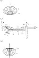
- the figure 5 is a schematic representation of a variant of the luminous device 2 of the first embodiment of the invention, illustrated in figure 1 .
- This variant of differs from the figure 1 in that the components of the light device 2' are turned over by 180° with respect to the optical axis 8, all other things possibly being equal.
- the light beam produced 12' is shown in figure 6 which is to be compared to figure 4 .
- a reversal of the light image can be observed, namely with an upper horizontal cutoff and a strong concentration of light under and at the level of the horizontal axis.
- This light beam is particularly suitable for performing a lighting function of the “code” (“low-beam”) type.
- the figure 7 is a schematic view of a light device according to a second embodiment of the invention.
- the reference numbers of the first embodiment are used to designate identical or corresponding elements, these numbers however being increased by 100. Reference is also made to the description of these elements within the framework of the first embodiment. Specific numbers between 100 and 200 are used to designate elements specific to this embodiment.
- This second embodiment differs from the first embodiment at the figure 1 essentially in that the mirror configured to form a virtual image of the light source and the reflecting surface is arranged differently, namely at the level of the optical axis 108 or at least close to it.
- the mirror 107 extends in fact along the optical axis 108, the latter being advantageously aligned with the support of the light source 104.
- the reflective surface 106.2 of the collector is configured to reflect towards the mirror the rays emitted by the source. light 104. These reflected rays correspond to virtual images 106.2 and 104 of the reflective surface 106.2 and of the light source 104, shown in broken lines.
- the light beam produced 112 will then correspond essentially to the light beam 12 of the first embodiment, illustrated in figure 4 .
- the lens 110 may have a focal point 110.3 advantageously located between the virtual light source and the virtual reflecting surface.
- the focal point 110.3 in question is advantageously located on a zone 106.3 located between the virtual image 106.2 of the reflecting surface 106.2 and the virtual image 104 of the light source 104.
- the focal point can be located on the virtual image 106.2 of the reflective surface 106.2, axially (that is to say along the optical axis) behind the virtual image 104 of the light source 104. It should be noted that it is also possible for this focus to be located at the rear or at the front of the virtual image 106.2 of the reflective surface 106.2 of the collector 106 provided that it is close, preferably less than 10 mm, preferably less than 5 mm.
- the mirror 107 more particularly its flat reflective surface 107.2 is advantageously parallel to the optical axis 108. It can however be inclined with respect to said axis, for example by an angle less than or equal to 10 °.
- the light source 104 and the collector 106 are advantageously a first light source and a first collector, the device then possibly comprising a second light source and a second collector.
- the first light source 104 and the first collector 106, on the one hand, and the second light source and the second collector, on the other hand, can be opposed with respect to the optical axis 8. Alternatively, they can be placed side by side.
- the figure 8 is a schematic representation of a variant of the light device 102 of the second embodiment of the invention illustrated in figure 7 .
- This variant differs from the figure 7 in that the components of the light device 102' are rotated 180° with respect to the optical axis 108, all other things being equal.
- the light beam produced 112' essentially corresponds to the light beam 12' produced by the light device of the figure 5 and illustrated in figure 6 .
- This is a light image reversed in relation to that of the light beam 112 produced by the light device of the figure 7 , essentially corresponding to that of the figure 4 , namely with an upper horizontal cut-off and a light concentration force under and at the level of the horizontal axis H.
- This light beam is particularly suitable for performing a “code” type (“low-beam” in English).
- the light devices which have just been described are particularly advantageous in that, by imaging the illuminated reflective surface, they make it possible to produce light beams with a concentration of light at a vertically off-center position. These beams are particularly useful for carrying out the “code” (“low-beam” in English) and “route” (“high-beam” in English) functions.
- these light devices through the use of a mirror, make it possible to turn over the light source and the collector associated with the light source, and thus accommodate bulk constraints.
Description
L'invention a trait au domaine de l'éclairage et de la signalisation lumineuse, plus particulièrement dans le domaine automobile.The invention relates to the field of lighting and light signaling, more particularly in the automotive field.
Le document de brevet publié
Un tel dispositif lumineux présente l'inconvénient de requérir une précision importante au niveau du positionnement de la plieuse et du bord de coupure. Aussi, la lentille de projection doit être une lentille épaisse en raison de sa faible distance focale, ce qui augmente son poids et complique sa production, comme notamment des défauts de retassures. De plus, le collecteur présente une certaine hauteur et, partant, un certain encombrement en hauteur.Such a light device has the disadvantage of requiring high precision in the positioning of the folder and the cutting edge. Also, the projection lens must be a thick lens due to its short focal length, which increases its weight and complicates its production, such as shrinkage defects in particular. In addition, the collector has a certain height and, therefore, a certain overall height.
Les documents
L'invention a pour objectif de pallier au moins un des inconvénients de l'état de la technique susmentionné. Plus particulièrement, l'invention a pour objectif de proposer un module ou dispositif lumineux d'éclairage et/ou de signalisation qui soit compact et plus économique à produire.The object of the invention is to overcome at least one of the drawbacks of the aforementioned state of the art. More particularly, the object of the invention is to propose a luminous module or device for lighting and/or signaling which is compact and more economical to produce.
L'invention , définie dans la revendication 1, a pour objet un dispositif lumineux, notamment pour véhicule automobile, comprenant une source lumineuse apte à émettre des rayons lumineux ; un collecteur avec une surface réfléchissante configurée pour collecter et réfléchir les rayons lumineux émis par la source lumineuse ; un système optique configuré pour projeter les rayons lumineux provenant de la surface réfléchissante en un faisceau lumineux suivant un axe optique du dispositif lumineux ; remarquable en ce que le dispositif lumineux comprend un miroir configuré pour former une image virtuelle de la source lumineuse et de la surface réfléchissante du collecteur, et le système optique est configuré pour former une image de ladite image virtuelle.The invention, defined in claim 1, relates to a light device, in particular for a motor vehicle, comprising a light source capable of emitting light rays; a collector with a reflecting surface configured to collect and reflect the light rays emitted by the light source; an optical system configured to project the light rays coming from the reflecting surface into a light beam along an optical axis of the light device; remarkable in that the luminous device comprises a mirror configured to form a virtual image of the light source and of the reflective surface of the collector, and the optical system is configured to form an image of said virtual image.
La source lumineuse et la surface réfléchissante forment un module lumineux. Un module lumineux est apte à former un faisceau lumineux. Le dispositif lumineux peut comprendre plusieurs modules lumineux. En présence d'un seul module lumineux, le dispositif lumineux est assimilable au module lumineux. Le dispositif lumineux forme un assemblage autonome en ce que chacun de ses composants, comme par exemple la ou les sources lumineuses, le ou les collecteurs et le système optique, est rigidement lié aux autres des composants, notamment via un support spécifique (non détaillé), et est ainsi positionné optiquement par rapport aux autres composants. Un ou plusieurs dispositifs lumineux peuvent ainsi être disposés dans un boîtier de projecteur afin de réaliser, le cas échéant en combinaison, toutes les fonctions réglementaires d'éclairage et de signalisation.The light source and the reflective surface form a light module. A light module is able to form a light beam. The light device may comprise several light modules. In the presence of a single luminous module, the luminous device is comparable to the luminous module. The light device forms an autonomous assembly in that each of its components, such as for example the light source(s), the collector(s) and the optical system, is rigidly linked to the other components, in particular via a specific support (not detailed) , and is thus optically positioned relative to the other components. One or more lighting devices can thus be arranged in a headlamp housing in order to perform, where appropriate in combination, all the regulatory lighting and signaling functions.
Selon un mode avantageux de l'invention, la surface réfléchissante du collecteur et le miroir sont configurés pour que les rayons lumineux réfléchis par une partie arrière de ladite surface réfléchissante soient parallèles à l'axe optique ou présentent, dans un plan vertical et par rapport audit axe, un angle d'inclinaison inférieur ou égal à 25°, préférentiellement inférieur ou égal à 10°.According to an advantageous embodiment of the invention, the reflective surface of the collector and the mirror are configured so that the light rays reflected by a rear part of said reflective surface are parallel to the optical axis or present, in a vertical plane and relative to said axis, an angle of inclination less than or equal to 25°, preferably less than or equal to 10°.
Selon un mode avantageux de l'invention, le miroir est plan et parallèle à l'axe optique ou est incliné par rapport audit axe optique d'un angle inférieur à 10°.According to an advantageous mode of the invention, the mirror is plane and parallel to the optical axis or is inclined with respect to said optical axis by an angle less than 10°.
Selon un mode avantageux de l'invention, la source lumineuse est configurée pour émettre les rayons lumineux dans une direction principale perpendiculaire à l'axe optique ou inclinée par rapport à une direction perpendiculaire audit axe optique d'un angle inférieur à 25°.According to an advantageous embodiment of the invention, the light source is configured to emit the light rays in a main direction perpendicular to the optical axis or inclined with respect to a direction perpendicular to said optical axis by an angle less than 25°.
Selon un mode avantageux de l'invention, la surface réfléchissante du collecteur présente un profil parabolique ou elliptique. De préférence, elle est une surface de révolution dudit profil. La révolution est autour d'un axe avantageusement parallèle à l'axe optique. Selon une variante, la surface réfléchissante est une surface de forme libre (en langue anglaise « free form ») ou une surface balayée ou une surface asymétrique. Elle peut aussi comporter plusieurs secteurs.According to an advantageous embodiment of the invention, the reflective surface of the collector has a parabolic or elliptical profile. Preferably, it is a surface of revolution of said profile. The revolution is around an axis advantageously parallel to the optical axis. According to a variant, the reflecting surface is a free-form surface or a swept surface or an asymmetrical surface. It can also include several sectors.
Selon un mode avantageux de l'invention, le miroir s'étend dans un prolongement, vers le système optique, de la surface réfléchissante du collecteur.According to an advantageous mode of the invention, the mirror extends in an extension, towards the optical system, of the reflective surface of the collector.
Selon un mode avantageux de l'invention, la surface réfléchissante du collecteur est configurée pour réfléchir les rayons lumineux émis par la source lumineuse suivant une direction principale divergente avec l'axe optique.According to an advantageous embodiment of the invention, the reflective surface of the collector is configured to reflect the light rays emitted by the light source in a main direction divergent with the optical axis.
Selon un mode avantageux de l'invention, la source lumineuse est disposée sur un substrat, le miroir étant aligné avec ledit substrat.According to an advantageous mode of the invention, the light source is arranged on a substrate, the mirror being aligned with said substrate.
Selon un mode avantageux de l'invention, la surface réfléchissante du collecteur est configurée pour réfléchir les rayons lumineux émis par la source lumineuse suivant une direction principale convergente avec l'axe optique, ledit axe optique passant par le substrat.According to an advantageous embodiment of the invention, the reflective surface of the collector is configured to reflect the light rays emitted by the light source in a main direction converging with the optical axis, said optical axis passing through the substrate.
Selon l'invention, le système optique présente un foyer situé sur une zone située entre la source lumineuse virtuelle et la surface réfléchissante virtuelle.According to the invention, the optical system has a focus located on a zone located between the virtual light source and the virtual reflecting surface.
Selon un mode avantageux de l'invention, le foyer du système optique est situé sur la surface réfléchissante virtuelle, à l'arrière de la source lumineuse virtuelle suivant l'axe optique.According to an advantageous mode of the invention, the focal point of the optical system is located on the virtual reflecting surface, at the rear of the virtual light source along the optical axis.
Selon un mode avantageux de l'invention, le système optique comprend une lentille correspondant à une portion de lentille convergente centrée sur un axe optique virtuel parallèle à l'axe optique et passant par le foyer du système optique.According to an advantageous embodiment of the invention, the optical system comprises a lens corresponding to a converging lens portion centered on a virtual optical axis parallel to the optical axis and passing through the focal point of the optical system.
Selon un mode avantageux de l'invention, la surface réfléchissante du collecteur présente un bord arrière, le faisceau lumineux étant un faisceau à coupure horizontale, ladite coupure étant une image dudit bord arrière.According to an advantageous embodiment of the invention, the reflective surface of the collector has a rear edge, the light beam being a horizontal cut-off beam, said cut-off being an image of said rear edge.
Selon un mode avantageux de l'invention, la source lumineuse et le collecteur sont situés au-dessus de l'axe optique lorsque le dispositif lumineux est en position fonctionnelle, la coupure du faisceau lumineux étant une coupure inférieure.According to an advantageous embodiment of the invention, the light source and the collector are located above the optical axis when the light device is in the functional position, the cutoff of the light beam being a lower cutoff.
Selon un mode avantageux de l'invention, la source lumineuse et le collecteur sont situés en-dessous de l'axe optique lorsque le dispositif lumineux est en position fonctionnelle, la coupure du faisceau lumineux étant une coupure supérieure.According to an advantageous embodiment of the invention, the light source and the collector are located below the optical axis when the light device is in the functional position, the cutoff of the light beam being an upper cutoff.
Selon un mode avantageux de l'invention, la source lumineuse, le collecteur et le faisceau lumineux sont une première source lumineuse, un premier collecteur et un premier faisceau lumineux, respectivement, le dispositif lumineux comprenant une deuxième source lumineuse et un deuxième collecteur avec une surface réfléchissante configurée pour collecter et réfléchir les rayons lumineux émis par la deuxième source lumineuse, le système optique étant configuré pour projeter les rayons lumineux provenant de ladite surface réfléchissante en un deuxième faisceau lumineux suivant un axe optique du dispositif et correspondant à une image de ladite surface réfléchissante.According to an advantageous mode of the invention, the light source, the collector and the light beam are a first light source, a first collector and a first light beam, respectively, the light device comprising a second light source and a second collector with a reflective surface configured to collect and reflect the light rays emitted by the second light source, the optical system being configured to project the light rays coming from said reflective surface into a second light beam along an optical axis of the device and corresponding to an image of said reflective surface.
Le premier collecteur et la première source lumineuse forment un premier module lumineux et le deuxième collecteur et la deuxième source lumineuse forment un deuxième module lumineux.The first collector and the first light source form a first light module and the second collector and the second light source form a second light module.
Avantageusement, le dispositif lumineux est configuré pour que le deuxième faisceau lumineux soit une image réelle de la surface réfléchissante du deuxième collecteur éclairée par la deuxième source lumineuse. A cet effet, les rayons lumineux réfléchis par la surface réfléchissante du deuxième collecteur sont transmis au système optique sans être réfléchis par un miroir, contrairement aux rayons lumineux réfléchis par la surface réfléchissante du premier collecteur.Advantageously, the light device is configured so that the second light beam is a real image of the reflecting surface of the second collector illuminated by the second light source. To this end, the light rays reflected by the reflecting surface of the second collector are transmitted to the optical system without being reflected by a mirror, unlike the light rays reflected by the reflecting surface of the first collector.
Selon un mode avantageux de l'invention, le premier collecteur et la première source lumineuse sont opposés, par rapport à l'axe optique, au deuxième collecteur et à la deuxième source lumineuse, respectivement ; ou le premier collecteur et la première source lumineuse, d'une part, et le deuxième collecteur et la deuxième source lumineuse, d'autre part, sont disposés côte-à-côte.According to an advantageous embodiment of the invention, the first collector and the first light source are opposed, with respect to the optical axis, to the second collector and to the second light source, respectively; or the first collector and the first light source, on the one hand, and the second collector and the second light source, on the other hand, are arranged side by side.
Les mesures de l'invention sont intéressantes en ce qu'elles permettent de réaliser un module ou dispositif lumineux compact, d'assemblage facile avec un nombre de pièces réduit et apte à réaliser différentes fonctions d'éclairage et/ou de signalisation. Plus particulièrement, le fait d'imager la surface réfléchissante éclairée du collecteur permet de réaliser un faisceau lumineux avec une concentration de lumière à une position décentrée verticalement dudit faisceau. Aussi, l'invention permet de très facilement retourner l'image produite et ainsi de moduler le ou les faisceaux lumineux aux fonctions d'éclairage et/ou de signalisation à assurer, en particulier les fonctions d'éclairage « code » et « route ».The measures of the invention are advantageous in that they make it possible to produce a compact luminous module or device, easy to assemble with a reduced number of parts and able to carry out various lighting and/or signaling functions. More particularly, the fact of imaging the illuminated reflective surface of the collector makes it possible to produce a light beam with a concentration of light at a vertically off-center position of said beam. Also, the invention makes it very easy to return the image produced and thus to modulate the light beam or beams to the lighting and/or signaling functions to be provided, in particular the "dipped" and "highway" lighting functions. .
D'autres caractéristiques et avantages de la présente invention seront mieux compris à l'aide de la description et des dessins.Other features and advantages of the present invention will be better understood from the description and the drawings.
-
[
Fig 1 ] est une représentation schématique d'un dispositif lumineux selon un premier mode de réalisation de l'invention.[Fig 1 ] is a schematic representation of a light device according to a first embodiment of the invention. -
[
Fig 2 ] est une vue en perspective du collecteur supérieur du dispositif lumineux de lafigure 1 .[Fig 2 ] is a perspective view of the upper collector of the luminous device of thefigure 1 . -
[
Fig 3 ] est une vue de la surface intérieure éclairée du collecteur du dispositif lumineux de lafigure 1 , depuis l'extérieur suivant l'axe optique.[Fig.3 ] is a view of the illuminated interior surface of the collector of the luminous device of thefigure 1 , from the outside along the optical axis. -
[
Fig 4 ] est une représentation graphique de l'image lumineuse du faisceau d'éclairage produit par le dispositif lumineux de lafigure 1 .[Fig 4 ] is a graphical representation of the light image of the illuminating beam produced by the light device of thefigure 1 . -
[
Fig 5 ] est une représentation schématique d'un dispositif lumineux selon une variante du premier mode de réalisation de l'invention.[Fig.5 ] is a schematic representation of a light device according to a variant of the first embodiment of the invention. -
[
Fig 6 ] est une représentation graphique de l'image lumineuse du faisceau d'éclairage produit par le dispositif lumineux de lafigure 5 .[Fig 6 ] is a graphical representation of the light image of the illuminating beam produced by the light device of thefigure 5 . -
[
Fig 7 ] est une représentation schématique d'un dispositif lumineux selon un deuxième mode de réalisation de l'invention.[Fig 7 ] is a schematic representation of a light device according to a second embodiment of the invention. -
[
Fig 8 ] est une représentation schématique d'un dispositif lumineux selon une variante du deuxième mode de réalisation de l'invention.[Fig.8 ] is a schematic representation of a light device according to a variant of the second embodiment of the invention.
Dans la description qui va suivre, les notions de « au-dessus » et « en-dessous » de l'axe optique du dispositif lumineux sont à comprendre lorsque le dispositif lumineux est en position fonctionnelle, c'est-à-dire avec une orientation qui correspond à celle pour laquelle il a été conçu. Similairement, les notions « avant » et « arrière » sont à comprendre suivant la direction générale de la lumière, suivant l'axe optique, lorsque le dispositif lumineux est en position fonctionnelle.In the following description, the notions of "above" and "below" the optical axis of the light device are to be understood when the light device is in the functional position, that is to say with a orientation corresponding to that for which it was designed. Similarly, the notions “front” and “rear” are to be understood along the general direction of the light, along the optical axis, when the luminous device is in the functional position.
Les
La
La source lumineuse 4 est avantageusement du type à semi-conducteur, comme notamment une diode à électroluminescence. La source lumineuse 4 émet des rayons lumineux dans un demi-espace délimité par le plan principal de ladite source, selon l'exemple représenté, dans une direction principale perpendiculaire audit plan et à l'axe optique 8. Selon l'invention, la direction principale d'émission pourra être inclinée par rapport à une direction perpendiculaire à l'axe optique d'un angle inférieur ou égal à 25°.The
Le collecteur 6 comprend un support 6.1, en forme de coque ou calotte, et une surface réfléchissante 6.2 sur la face intérieure du support 6.1. La surface réfléchissante 6.2 est avantageusement de profil du type elliptique ou parabolique ou « free form ». Le dispositif lumineux 2 comprend également un miroir 7 disposé dans le prolongement de la surface réfléchissante 6.2 du collecteur 6. Le miroir 7 comprend un support 7.1 et une surface réfléchissante plane 7.2 formée sur le support 7.1. Ce dernier peut être confondu ou adjacent au support 6.1 du collecteur. La surface réfléchissante 6.2 du collecteur 6 est avantageusement une surface de révolution autour d'un axe parallèle à l'axe optique 8. Alternativement, il peut s'agir d'une surface de forme libre (en langue anglaise « free form ») ou une surface balayée ou une surface asymétrique. Elle peut aussi comporter plusieurs secteurs. L'expression « type parabolique » s'applique de manière générale à des réflecteurs dont la surface présente un seul foyer, c'est-à-dire une zone de convergence des rayons lumineux telle que les rayons lumineux émis par une source lumineuse placée au niveau de cette zone de convergence sont projetés à grande distance après réflexion sur la surface. Projeté à grande distance signifie que ces rayons lumineux ne convergent pas vers une zone située à au moins 10 fois les dimensions du réflecteur. Autrement dit les rayons réfléchis ne convergent pas vers une zone de convergence ou, s'ils convergent, cette zone de convergence est située à une distance supérieure ou égale à 10 fois les dimensions du réflecteur. Une surface de type parabolique peut donc présenter ou non des portions paraboliques. Un réflecteur présentant une telle surface est généralement utilisé seul pour créer un faisceau lumineux. Alternativement il peut être utilisé comme surface de projection associée à un réflecteur de type elliptique. Dans ce cas la source lumineuse du réflecteur de type parabolique est la zone de convergence des rayons réfléchis par le réflecteur de type elliptique.The
Le miroir 7, plus particulièrement sa surface réfléchissante plane 7.2 est avantageusement parallèle à l'axe optique 8. Elle peut cependant être inclinée par rapport audit axe, par exemple d'un angle inférieur ou égal à 10°. Si elle est inclinée, le miroir est avantageusement divergent avec l'axe optique dans la direction principale de propagation de la lumière, c'est-à-dire de la source lumineuse 4 vers la lentille de projection 10.The
Le collecteur 6 en forme de coque ou de calotte est avantageusement réalisé dans des matériaux présentant une bonne tenue à la chaleur, par exemple du verre ou des polymères synthétiques comme du polycarbonate PC ou du polyétherimide PEI.The
La source lumineuse 4 est disposée à un foyer de la surface réfléchissante 6.2 du collecteur 6 de manière à ce que ses rayons soient collectés et réfléchis vers le miroir 7. Ce dernier forme une image virtuelle 6.2 de la surface réfléchissante 6.2 et une image virtuelle 4 de la source lumineuse 4, représentées en trait interrompu à la
La lentille de projection 10 présente une première face d'entrée 10.1 et face de sortie 10.2. La lentille 10 est dite mince, par exemple avec une épaisseur suivant l'axe optique qui est inférieure à 7mm, notamment en raison de la faible hauteur de lentille et de la longue focale de celle-ci. La lentille 10 peut présenter un foyer 10.3 avantageusement situé entre la source lumineuse virtuelle et la surface réfléchissante virtuelle. Le foyer 10.3 en question est avantageusement situé sur une zone 6.3 située entre les images virtuelles 6.2 et 4 de la surface réfléchissante 6.2 et de la source lumineuse 4. En l'occurrence le foyer peut être situé sur l'image virtuelle 6.2 de la surface réfléchissante 6.2, axialement (c'est-à-dire suivant l'axe optique) en arrière de l'image virtuelle 4 de la source lumineuse virtuelle 4. Il est à noter qu'il est aussi possible que ce foyer soit situé à l'arrière ou à l'avant de l'image virtuelle de la surface réfléchissante 6.2 du collecteur 6 pour autant que ce soit à proximité, de préférence à moins de 10 mm, préférentiellement moins de 5 mm.The
Il est aussi à noter que la lentille 10 est avantageusement du type convergent symétrique par rapport l'axe optique virtuel 8 (en trait interrompu) situé au-dessus de l'axe optique 8 et avantageusement passant par le foyer 10.3.It should also be noted that the
La surface réfléchissante 6.2 du collecteur 6, si elle est du type elliptique, présente un deuxième foyer situé à l'avant de la lentille 10 et à distance de l'axe optique 8. Il est à noter qu'il est aussi possible que ce foyer soit situé à l'arrière de la lentille et/ou sur l'axe optique, pour autant que ce soit à proximité de la lentille, de manière à réduire la largeur du faisceau au niveau de la face d'entrée de la lentille.The reflective surface 6.2 of the
La source lumineuse 4 et le collecteur 6 sont avantageusement une première source lumineuse et un premier collecteur, le dispositif pouvant alors comprendre une deuxième source lumineuse 14 et un deuxième collecteur 16 (représentés en trait interrompu). En l'occurrence, la première source lumineuse 4 et le premier collecteur 6, formant un premier module lumineux, et la deuxième source lumineuse 14 et le deuxième collecteur 16, formant un deuxième module lumineux, sont opposés par rapport à l'axe optique 8. Plus particulièrement, les première et deuxième sources lumineuses 4 et 14 sont sur des faces opposées d'un substrat commun par lequel passe l'axe optique 8.The
La
La
La
On peut observer à la
Ce faisceau lumineux 12 est ainsi particulièrement adapté pour réaliser une fonction d'éclairage du type « route » (« high-beam » en anglais) en complément d'une fonction d'éclairage du type « code » (« low-beam » en anglais).This
La
Le faisceau lumineux produit 12' est illustré à la
La
Ce deuxième mode de réalisation se distingue du premier mode de réalisation à la
Similairement au premier mode de réalisation, la lentille 110 peut présenter un foyer 110.3 avantageusement situé entre la source lumineuse virtuelle et la surface réfléchissante virtuelle. Le foyer 110.3 en question est avantageusement situé sur une zone 106.3 située entre l'image virtuelle 106.2 de la surface réfléchissante 106.2 et l'image virtuelle 104 de la source lumineuse 104. En l'occurrence le foyer peut être situé sur l'image virtuelle 106.2 de la surface réfléchissante 106.2, axialement (c'est-à-dire suivant l'axe optique) en arrière de l'image virtuelle 104 de la source lumineuse 104. Il est à noter qu'il est aussi possible que ce foyer soit situé à l'arrière ou à l'avant de l'image virtuelle 106.2 de la surface réfléchissante 106.2 du collecteur 106 pour autant que ce soit à proximité, de préférence à moins de 10 mm, préférentiellement moins de 5 mm.Similar to the first embodiment, the
Encore similairement au premier mode de réalisation, le miroir 107, plus particulièrement sa surface réfléchissante plane 107.2 est avantageusement parallèle à l'axe optique 108. Elle peut cependant être inclinée par rapport audit axe, par exemple d'un angle inférieur ou égal à 10°.Still similarly to the first embodiment, the
Toujours similairement au premier mode de réalisation, la source lumineuse 104 et le collecteur 106 sont avantageusement une première source lumineuse et un premier collecteur, le dispositif pouvant alors comprendre une deuxième source lumineuse et un deuxième collecteur. En l'occurrence, la première source lumineuse 104 et le premier collecteur 106, d'un part, et la deuxième source lumineuse et le deuxième collecteur, d'autre part, peuvent être opposés par rapport à l'axe optique 8. Alternativement, ils peuvent être disposés côte-à-côte.Still similar to the first embodiment, the
La
Le faisceau lumineux produit 112' correspond essentiellement au faisceau lumineux 12' produit par le dispositif lumineux de la
De manière générale, les dispositifs lumineux qui viennent d'être décrits sont particulièrement intéressants en ce que, en imageant la surface réfléchissante éclairée, ils permettent de réaliser des faisceaux lumineux avec une concentration de lumière à une position décentrée verticalement. Ces faisceaux sont particulièrement utiles pour réaliser les fonctions « code » (« low-beam » en anglais) et « route » (« high-beam » en anglais). De plus, ces dispositifs lumineux, de par l'utilisation d'un miroir, permettent de retourner la source lumineuse et le collecteur associé à la source lumineuse, et ainsi s'accommoder de contraintes d'encombrement.In general, the light devices which have just been described are particularly advantageous in that, by imaging the illuminated reflective surface, they make it possible to produce light beams with a concentration of light at a vertically off-center position. These beams are particularly useful for carrying out the “code” (“low-beam” in English) and “route” (“high-beam” in English) functions. In addition, these light devices, through the use of a mirror, make it possible to turn over the light source and the collector associated with the light source, and thus accommodate bulk constraints.
Claims (16)
- Luminous device (2; 102), in particular for a motor vehicle, comprising:- a light source (4; 104) able to emit light rays;- a collector (6; 106) with a reflective surface (6.2; 106.2) configured to collect and reflect the light rays emitted by the light source (4; 104);- an optical system (10; 110) configured to project the light rays coming from the reflective surface (6.2; 106.2) into a light beam (12; 112) along an optical axis of the luminous device (8; 108);the luminous device (2; 102) comprising a mirror (7; 107) configured to form a virtual image (4, 6.2; 104, 106.2) of the light source and of the reflective surface of the collector (6; 106), and the optical system (10; 110) being configured to form an image of said virtual image (4, 6.2; 104, 106.2)
characterized in that the optical system (10; 110) has a focal point (10.3; 110.3) located in a region located between the virtual image (4; 104) of the light source (4; 104) and the virtual image (6.2; 106.2) of the reflective surface (6.2; 106.2). - Luminous device (2; 102) according to Claim 1, characterized in that the reflective surface (6.2; 106.2) of the collector (6; 106) and the mirror (7; 107) are configured so that the light rays reflected by a rear portion of said reflective surface (6.2; 106.2) are parallel to the optical axis (8, 108) or have, in a vertical plane with respect to said axis, an angle of inclination smaller than or equal to 25°, and preferably smaller than or equal to 10°.
- Luminous device (2; 102) according to one of Claims 1 and 2, characterized in that the mirror (7; 107) is planar and parallel to the optical axis (8; 108) or is inclined with respect to said optical axis by an angle smaller than 10°.
- Luminous device (2; 102) according to one of Claims 1 to 3, characterized in that the light source (4; 104) is configured to emit light rays in a main direction that is perpendicular to the optical axis (8; 108) or that is inclined with respect to a direction perpendicular to said optical axis by an angle smaller than 25°.
- Luminous device (2; 102) according to one of Claims 1 to 4, characterized in that the reflective surface (6.2; 106.2) of the collector (6; 106) has a parabolic or elliptical profile.
- Luminous device (2) according to one of Claims 1 to 5, characterized in that the mirror (7) forms an extension, toward the optical system (10), of the reflective surface (6.2) of the collector (6).
- Luminous device (2) according to one of Claims 1 to 6, characterized in that the reflective surface (6.2) of the collector (2) is configured to reflect the light rays emitted by the light source (4) in a main direction that is divergent with the optical axis (8).
- Luminous device (102) according to one of Claims 1 to 5, characterized in that the light source (104) is placed on a substrate (118), the mirror (7) being aligned with said substrate (118).
- Luminous device (102) according to Claim 8, characterized in that the reflective surface (106.2) of the collector (6) is configured to reflect the light rays emitted by the light source (104) in a main direction that is convergent with the optical axis (108), said optical axis passing through the substrate (118).
- Luminous device (2; 102) according to one of Claims 1 to 9, characterized in that the focal point (10.3; 110.3) of the optical system (10; 110) is located on the virtual image (6.2; 106.2) of the reflective surface (6.2; 106.2), behind the virtual image (4; 104) of the virtual light source (4; 104) along the optical axis (8; 108).
- Luminous device (2; 102) according to Claim 10, characterized in that the optical system comprises a lens (10; 110) corresponding to a segment of a convergent lens centred on a virtual optical axis (8; 108) parallel to the optical axis (8; 108) and passing through the focal point (10.3; 110.3) of the optical system.
- Luminous device (2; 102) according to one of Claims 1 to 11, characterized in that the reflective surface (6.2; 106.2) of the collector (6; 106) has a rear edge (6.2.1; 106.2.1), the light beam (12; 112) being a beam containing a flat cutoff, said cutoff being an image of said rear edge.
- Luminous device (2; 102) according to Claim 12, characterized in that the light source (4; 104) and the collector (6; 106) are located above the optical axis (8; 108) when the luminous device is in functional position, the cutoff of the light beam (12; 112) being a lower cutoff.
- Luminous device (2'; 102') according to Claim 12, characterized in that the light source (4; 104) and the collector (6; 106) are located below the optical axis (8; 108) when the luminous device is in functional position, the cutoff of the light beam (12'; 112') being an upper cutoff.
- Luminous device (2) according to one of Claims 1 to 14, characterized in that the light source (4; 104), the collector (6; 106) and the light beam (12; 112) are a first light source, a first collector and a first light beam, respectively, the luminous device comprising a second light source (14) and a second collector (16) with a reflective surface configured to collect and reflect the light rays emitted by the second light source (14), the optical system (10; 110) being configured to project the light rays coming from said reflective surface into a second light beam along an optical axis of the device and corresponding to an image of said reflective surface.
- Luminous device according to Claim 15, characterized in that the first collector (6; 106) and the first light source (4; 104) are opposite, with respect to the optical axis (8; 108), to the second collector (16) and to the second light source (14), respectively; or the first collector and the first light source, on the one hand, and the second collector and the second light source, on the other hand, are placed side-by-side.
Priority Applications (1)
| Application Number | Priority Date | Filing Date | Title |
|---|---|---|---|
| EP22198166.5A EP4134586A1 (en) | 2019-03-14 | 2020-02-21 | Lighting device imaging a virtual illuminated surface of a collector |
Applications Claiming Priority (1)
| Application Number | Priority Date | Filing Date | Title |
|---|---|---|---|
| FR1902615A FR3093788B1 (en) | 2019-03-14 | 2019-03-14 | LIGHT DEVICE IMAGES A VIRTUAL ILLUMINATED SURFACE OF A COLLECTOR |
Related Child Applications (2)
| Application Number | Title | Priority Date | Filing Date |
|---|---|---|---|
| EP22198166.5A Division-Into EP4134586A1 (en) | 2019-03-14 | 2020-02-21 | Lighting device imaging a virtual illuminated surface of a collector |
| EP22198166.5A Division EP4134586A1 (en) | 2019-03-14 | 2020-02-21 | Lighting device imaging a virtual illuminated surface of a collector |
Publications (2)
| Publication Number | Publication Date |
|---|---|
| EP3708905A1 EP3708905A1 (en) | 2020-09-16 |
| EP3708905B1 true EP3708905B1 (en) | 2022-11-09 |
Family
ID=67383999
Family Applications (2)
| Application Number | Title | Priority Date | Filing Date |
|---|---|---|---|
| EP22198166.5A Pending EP4134586A1 (en) | 2019-03-14 | 2020-02-21 | Lighting device imaging a virtual illuminated surface of a collector |
| EP20158866.2A Active EP3708905B1 (en) | 2019-03-14 | 2020-02-21 | Lighting device imaging the mirrored image of a light collector |
Family Applications Before (1)
| Application Number | Title | Priority Date | Filing Date |
|---|---|---|---|
| EP22198166.5A Pending EP4134586A1 (en) | 2019-03-14 | 2020-02-21 | Lighting device imaging a virtual illuminated surface of a collector |
Country Status (7)
| Country | Link |
|---|---|
| US (1) | US10920949B2 (en) |
| EP (2) | EP4134586A1 (en) |
| JP (1) | JP2020149976A (en) |
| KR (1) | KR20200110215A (en) |
| CN (1) | CN111692568A (en) |
| FR (1) | FR3093788B1 (en) |
| PL (1) | PL3708905T3 (en) |
Families Citing this family (4)
| Publication number | Priority date | Publication date | Assignee | Title |
|---|---|---|---|---|
| US10215359B2 (en) * | 2016-01-29 | 2019-02-26 | Gentex Corporation | Indicator optic for vehicle lighting module |
| FR3084728B1 (en) * | 2018-07-31 | 2021-03-19 | Valeo Vision | LIGHT MODULE IMAGING THE ILLUMINATED SURFACE OF A COLLECTOR |
| FR3130011B1 (en) * | 2021-12-07 | 2024-04-05 | Valeo Vision | Lighting device of a motor vehicle |
| WO2024015767A1 (en) * | 2022-07-12 | 2024-01-18 | Muth Mirror Systems, Llc | Reflecting optic assembly |
Family Cites Families (23)
| Publication number | Priority date | Publication date | Assignee | Title |
|---|---|---|---|---|
| FR2830073B1 (en) * | 2001-09-27 | 2003-12-12 | Valeo Vision | ELLIPTICAL LIGHTING PROJECTOR FOR A MOTOR VEHICLE COMPRISING A SECONDARY OPTICAL SYSTEM |
| FR2839139B1 (en) * | 2002-04-25 | 2005-01-14 | Valeo Vision | LUMINAIRE-FREE ELLIPTICAL LIGHTING MODULE COMPRISING A CUT-OFF LIGHTING BEAM AND PROJECTOR COMPRISING SUCH A MODULE |
| JP2004349130A (en) * | 2003-05-22 | 2004-12-09 | Koito Mfg Co Ltd | Vehicular lighting fixture |
| FR2866411A1 (en) * | 2004-02-13 | 2005-08-19 | Valeo Vision | Headlight for motor vehicle, has additional reflector provided on side at level of recess opposite to optical axis of another reflector to collect portion of light from recess and provide supplementary beam not intercepted by lens |
| JP4526256B2 (en) * | 2003-10-17 | 2010-08-18 | スタンレー電気株式会社 | Light source module and lamp having the light source module |
| JP4108597B2 (en) * | 2003-12-24 | 2008-06-25 | 株式会社小糸製作所 | Vehicle lamp unit |
| JP4339143B2 (en) * | 2004-02-10 | 2009-10-07 | 株式会社小糸製作所 | Vehicle lamp unit |
| JP4563338B2 (en) * | 2006-04-18 | 2010-10-13 | 株式会社小糸製作所 | Vehicle headlamp lamp unit |
| JP4458067B2 (en) * | 2006-05-17 | 2010-04-28 | 市光工業株式会社 | Vehicle lighting |
| JP2008123753A (en) * | 2006-11-09 | 2008-05-29 | Koito Mfg Co Ltd | Lamp unit for vehicle |
| JP2009259468A (en) * | 2008-04-14 | 2009-11-05 | Ichikoh Ind Ltd | Vehicle lamp |
| JP5281359B2 (en) * | 2008-10-30 | 2013-09-04 | 株式会社小糸製作所 | Vehicle lamp unit and vehicle lamp |
| FR2940403B1 (en) * | 2008-12-19 | 2014-01-17 | Valeo Vision Sas | LIGHTING DEVICE FOR A VEHICLE HEADLAMP PROVIDING MULTIPLE LIGHTING FUNCTIONS OR A VARIABLE FUNCTION WITH A SINGLE LIGHT SOURCE |
| JP5423159B2 (en) * | 2009-06-04 | 2014-02-19 | スタンレー電気株式会社 | Vehicle lighting |
| DE102011013211B4 (en) * | 2011-03-05 | 2012-12-06 | Automotive Lighting Reutlingen Gmbh | Motor vehicle headlight with a multi-function projection module |
| US8939627B2 (en) * | 2011-07-29 | 2015-01-27 | Stanley Electric Co., Ltd. | Vehicle lighting unit |
| DE102012202290B4 (en) * | 2012-02-15 | 2014-03-27 | Automotive Lighting Reutlingen Gmbh | Light module for a glare-free motor vehicle high beam |
| US9243768B2 (en) * | 2012-03-06 | 2016-01-26 | Mitsubishi Electric Corporation | Light source for headlight and headlight |
| DE102013207845A1 (en) * | 2013-04-29 | 2014-10-30 | Automotive Lighting Reutlingen Gmbh | Light module for a motor vehicle headlight |
| KR102289755B1 (en) * | 2014-12-24 | 2021-08-13 | 에스엘 주식회사 | Low beam shield for head lamp |
| FR3038695A1 (en) * | 2015-07-10 | 2017-01-13 | Valeo Vision | LUMINOUS MODULE FOR LIGHTING AND / OR SIGNALING OF A MOTOR VEHICLE |
| FR3047541B1 (en) * | 2015-12-10 | 2019-10-04 | Valeo Vision | AUTOMOTIVE LIGHTING MODULE WITH COMBINED CODE AND ROAD FUNCTIONS AND ADJUSTABLE LIGHT SOURCE |
| FR3063795B1 (en) * | 2017-03-13 | 2019-04-05 | Valeo Vision | LUMINOUS DEVICE, IN PARTICULAR LIGHTING AND / OR SIGNALING, FOR MOTOR VEHICLE |
-
2019
- 2019-03-14 FR FR1902615A patent/FR3093788B1/en active Active
-
2020
- 2020-02-21 EP EP22198166.5A patent/EP4134586A1/en active Pending
- 2020-02-21 PL PL20158866.2T patent/PL3708905T3/en unknown
- 2020-02-21 EP EP20158866.2A patent/EP3708905B1/en active Active
- 2020-03-11 US US16/815,272 patent/US10920949B2/en active Active
- 2020-03-12 KR KR1020200030690A patent/KR20200110215A/en unknown
- 2020-03-13 CN CN202010176786.8A patent/CN111692568A/en active Pending
- 2020-03-13 JP JP2020044463A patent/JP2020149976A/en active Pending
Also Published As
| Publication number | Publication date |
|---|---|
| US10920949B2 (en) | 2021-02-16 |
| FR3093788A1 (en) | 2020-09-18 |
| CN111692568A (en) | 2020-09-22 |
| EP3708905A1 (en) | 2020-09-16 |
| PL3708905T3 (en) | 2023-03-13 |
| US20200292144A1 (en) | 2020-09-17 |
| JP2020149976A (en) | 2020-09-17 |
| FR3093788B1 (en) | 2022-05-27 |
| KR20200110215A (en) | 2020-09-23 |
| EP4134586A1 (en) | 2023-02-15 |
Similar Documents
| Publication | Publication Date | Title |
|---|---|---|
| EP3708904B1 (en) | Lighting device illustrating the lit surfaces of at least two manifolds | |
| EP3708905B1 (en) | Lighting device imaging the mirrored image of a light collector | |
| WO2020025171A1 (en) | Luminous module that images the illuminated surface of a collector | |
| EP2743567B1 (en) | Primary optical element, lighting module and headlight for motor vehicle | |
| EP3167226B1 (en) | Lighting module for a motor vehicle | |
| EP1528312B1 (en) | Lighting module for vehicle headlamp | |
| FR3047541B1 (en) | AUTOMOTIVE LIGHTING MODULE WITH COMBINED CODE AND ROAD FUNCTIONS AND ADJUSTABLE LIGHT SOURCE | |
| FR3050011A1 (en) | MODULE FOR TRANSMITTING A LUMINOUS BEAM FOR MOTOR VEHICLE PROJECTOR | |
| EP1500869A1 (en) | Elliptical lighting module without screen emitting a low beam and headlamp comprising the same | |
| EP3002504A2 (en) | Lighting module for lighting and/or signalling of a motor vehicle | |
| FR2853393A1 (en) | VEHICLE HEADLIGHT WITH PHOTOEMISSIVE DIODE | |
| WO2021099430A1 (en) | Combined luminous module that images the illuminated surface of a collector | |
| EP4264120A1 (en) | Motor vehicle headlamp with multiple lighting modules on an inclined common plate | |
| EP2976569B1 (en) | Illuminating and/or signalling module for an automotive vehicle | |
| WO2022129420A1 (en) | Light-emitting module that images the illuminated surface of a collector, with a blocker of parasitic rays | |
| EP3521692B1 (en) | Dual-function light module with common lit surface | |
| EP4051954B1 (en) | Headlamp adjustable between left-hand drive and right-hand drive | |
| EP2302292A1 (en) | Optical module with folder formed by a transparent material/air dioptre | |
| WO2022162180A1 (en) | Motor vehicle device for lighting the road | |
| EP4264123A1 (en) | Dual-function lighting device with rotating lens | |
| WO2024033122A1 (en) | Headlamp having a vertical cut-off and extension for a motor vehicle | |
| FR3133901A1 (en) | LIGHT MODULE IMAGING THE ILLUMINATED SURFACE OF A COLLECTOR WITH EXTRUDED PARASITIC RAY BLOCKER | |
| EP3575675A1 (en) | Light module with cut-off with area reflector |
Legal Events
| Date | Code | Title | Description |
|---|---|---|---|
| PUAI | Public reference made under article 153(3) epc to a published international application that has entered the european phase |
Free format text: ORIGINAL CODE: 0009012 |
|
| STAA | Information on the status of an ep patent application or granted ep patent |
Free format text: STATUS: THE APPLICATION HAS BEEN PUBLISHED |
|
| AK | Designated contracting states |
Kind code of ref document: A1 Designated state(s): AL AT BE BG CH CY CZ DE DK EE ES FI FR GB GR HR HU IE IS IT LI LT LU LV MC MK MT NL NO PL PT RO RS SE SI SK SM TR |
|
| AX | Request for extension of the european patent |
Extension state: BA ME |
|
| STAA | Information on the status of an ep patent application or granted ep patent |
Free format text: STATUS: REQUEST FOR EXAMINATION WAS MADE |
|
| 17P | Request for examination filed |
Effective date: 20210316 |
|
| RBV | Designated contracting states (corrected) |
Designated state(s): AL AT BE BG CH CY CZ DE DK EE ES FI FR GB GR HR HU IE IS IT LI LT LU LV MC MK MT NL NO PL PT RO RS SE SI SK SM TR |
|
| GRAP | Despatch of communication of intention to grant a patent |
Free format text: ORIGINAL CODE: EPIDOSNIGR1 |
|
| STAA | Information on the status of an ep patent application or granted ep patent |
Free format text: STATUS: GRANT OF PATENT IS INTENDED |
|
| INTG | Intention to grant announced |
Effective date: 20220530 |
|
| GRAS | Grant fee paid |
Free format text: ORIGINAL CODE: EPIDOSNIGR3 |
|
| GRAA | (expected) grant |
Free format text: ORIGINAL CODE: 0009210 |
|
| STAA | Information on the status of an ep patent application or granted ep patent |
Free format text: STATUS: THE PATENT HAS BEEN GRANTED |
|
| AK | Designated contracting states |
Kind code of ref document: B1 Designated state(s): AL AT BE BG CH CY CZ DE DK EE ES FI FR GB GR HR HU IE IS IT LI LT LU LV MC MK MT NL NO PL PT RO RS SE SI SK SM TR |
|
| REG | Reference to a national code |
Ref country code: GB Ref legal event code: FG4D Free format text: NOT ENGLISH |
|
| REG | Reference to a national code |
Ref country code: CH Ref legal event code: EP Ref country code: AT Ref legal event code: REF Ref document number: 1530589 Country of ref document: AT Kind code of ref document: T Effective date: 20221115 |
|
| REG | Reference to a national code |
Ref country code: DE Ref legal event code: R096 Ref document number: 602020006108 Country of ref document: DE |
|
| REG | Reference to a national code |
Ref country code: IE Ref legal event code: FG4D Free format text: LANGUAGE OF EP DOCUMENT: FRENCH |
|
| REG | Reference to a national code |
Ref country code: LT Ref legal event code: MG9D |
|
| REG | Reference to a national code |
Ref country code: NL Ref legal event code: MP Effective date: 20221109 |
|
| PG25 | Lapsed in a contracting state [announced via postgrant information from national office to epo] |
Ref country code: SE Free format text: LAPSE BECAUSE OF FAILURE TO SUBMIT A TRANSLATION OF THE DESCRIPTION OR TO PAY THE FEE WITHIN THE PRESCRIBED TIME-LIMIT Effective date: 20221109 Ref country code: PT Free format text: LAPSE BECAUSE OF FAILURE TO SUBMIT A TRANSLATION OF THE DESCRIPTION OR TO PAY THE FEE WITHIN THE PRESCRIBED TIME-LIMIT Effective date: 20230309 Ref country code: NO Free format text: LAPSE BECAUSE OF FAILURE TO SUBMIT A TRANSLATION OF THE DESCRIPTION OR TO PAY THE FEE WITHIN THE PRESCRIBED TIME-LIMIT Effective date: 20230209 Ref country code: LT Free format text: LAPSE BECAUSE OF FAILURE TO SUBMIT A TRANSLATION OF THE DESCRIPTION OR TO PAY THE FEE WITHIN THE PRESCRIBED TIME-LIMIT Effective date: 20221109 Ref country code: FI Free format text: LAPSE BECAUSE OF FAILURE TO SUBMIT A TRANSLATION OF THE DESCRIPTION OR TO PAY THE FEE WITHIN THE PRESCRIBED TIME-LIMIT Effective date: 20221109 Ref country code: ES Free format text: LAPSE BECAUSE OF FAILURE TO SUBMIT A TRANSLATION OF THE DESCRIPTION OR TO PAY THE FEE WITHIN THE PRESCRIBED TIME-LIMIT Effective date: 20221109 |
|
| PGFP | Annual fee paid to national office [announced via postgrant information from national office to epo] |
Ref country code: FR Payment date: 20230227 Year of fee payment: 4 Ref country code: CZ Payment date: 20230127 Year of fee payment: 4 |
|
| PG25 | Lapsed in a contracting state [announced via postgrant information from national office to epo] |
Ref country code: RS Free format text: LAPSE BECAUSE OF FAILURE TO SUBMIT A TRANSLATION OF THE DESCRIPTION OR TO PAY THE FEE WITHIN THE PRESCRIBED TIME-LIMIT Effective date: 20221109 Ref country code: LV Free format text: LAPSE BECAUSE OF FAILURE TO SUBMIT A TRANSLATION OF THE DESCRIPTION OR TO PAY THE FEE WITHIN THE PRESCRIBED TIME-LIMIT Effective date: 20221109 Ref country code: IS Free format text: LAPSE BECAUSE OF FAILURE TO SUBMIT A TRANSLATION OF THE DESCRIPTION OR TO PAY THE FEE WITHIN THE PRESCRIBED TIME-LIMIT Effective date: 20230309 Ref country code: HR Free format text: LAPSE BECAUSE OF FAILURE TO SUBMIT A TRANSLATION OF THE DESCRIPTION OR TO PAY THE FEE WITHIN THE PRESCRIBED TIME-LIMIT Effective date: 20221109 Ref country code: GR Free format text: LAPSE BECAUSE OF FAILURE TO SUBMIT A TRANSLATION OF THE DESCRIPTION OR TO PAY THE FEE WITHIN THE PRESCRIBED TIME-LIMIT Effective date: 20230210 |
|
| PGFP | Annual fee paid to national office [announced via postgrant information from national office to epo] |
Ref country code: PL Payment date: 20230206 Year of fee payment: 4 |
|
| PG25 | Lapsed in a contracting state [announced via postgrant information from national office to epo] |
Ref country code: NL Free format text: LAPSE BECAUSE OF FAILURE TO SUBMIT A TRANSLATION OF THE DESCRIPTION OR TO PAY THE FEE WITHIN THE PRESCRIBED TIME-LIMIT Effective date: 20221109 |
|
| P01 | Opt-out of the competence of the unified patent court (upc) registered |
Effective date: 20230528 |
|
| PG25 | Lapsed in a contracting state [announced via postgrant information from national office to epo] |
Ref country code: SM Free format text: LAPSE BECAUSE OF FAILURE TO SUBMIT A TRANSLATION OF THE DESCRIPTION OR TO PAY THE FEE WITHIN THE PRESCRIBED TIME-LIMIT Effective date: 20221109 Ref country code: RO Free format text: LAPSE BECAUSE OF FAILURE TO SUBMIT A TRANSLATION OF THE DESCRIPTION OR TO PAY THE FEE WITHIN THE PRESCRIBED TIME-LIMIT Effective date: 20221109 Ref country code: EE Free format text: LAPSE BECAUSE OF FAILURE TO SUBMIT A TRANSLATION OF THE DESCRIPTION OR TO PAY THE FEE WITHIN THE PRESCRIBED TIME-LIMIT Effective date: 20221109 Ref country code: DK Free format text: LAPSE BECAUSE OF FAILURE TO SUBMIT A TRANSLATION OF THE DESCRIPTION OR TO PAY THE FEE WITHIN THE PRESCRIBED TIME-LIMIT Effective date: 20221109 |
|
| REG | Reference to a national code |
Ref country code: DE Ref legal event code: R097 Ref document number: 602020006108 Country of ref document: DE |
|
| PG25 | Lapsed in a contracting state [announced via postgrant information from national office to epo] |
Ref country code: SK Free format text: LAPSE BECAUSE OF FAILURE TO SUBMIT A TRANSLATION OF THE DESCRIPTION OR TO PAY THE FEE WITHIN THE PRESCRIBED TIME-LIMIT Effective date: 20221109 Ref country code: AL Free format text: LAPSE BECAUSE OF FAILURE TO SUBMIT A TRANSLATION OF THE DESCRIPTION OR TO PAY THE FEE WITHIN THE PRESCRIBED TIME-LIMIT Effective date: 20221109 |
|
| PLBE | No opposition filed within time limit |
Free format text: ORIGINAL CODE: 0009261 |
|
| STAA | Information on the status of an ep patent application or granted ep patent |
Free format text: STATUS: NO OPPOSITION FILED WITHIN TIME LIMIT |
|
| PG25 | Lapsed in a contracting state [announced via postgrant information from national office to epo] |
Ref country code: MC Free format text: LAPSE BECAUSE OF FAILURE TO SUBMIT A TRANSLATION OF THE DESCRIPTION OR TO PAY THE FEE WITHIN THE PRESCRIBED TIME-LIMIT Effective date: 20221109 |
|
| REG | Reference to a national code |
Ref country code: CH Ref legal event code: PL |
|
| 26N | No opposition filed |
Effective date: 20230810 |
|
| REG | Reference to a national code |
Ref country code: BE Ref legal event code: MM Effective date: 20230228 |
|
| PG25 | Lapsed in a contracting state [announced via postgrant information from national office to epo] |
Ref country code: LU Free format text: LAPSE BECAUSE OF NON-PAYMENT OF DUE FEES Effective date: 20230221 Ref country code: LI Free format text: LAPSE BECAUSE OF NON-PAYMENT OF DUE FEES Effective date: 20230228 Ref country code: CH Free format text: LAPSE BECAUSE OF NON-PAYMENT OF DUE FEES Effective date: 20230228 |
|
| PG25 | Lapsed in a contracting state [announced via postgrant information from national office to epo] |
Ref country code: SI Free format text: LAPSE BECAUSE OF FAILURE TO SUBMIT A TRANSLATION OF THE DESCRIPTION OR TO PAY THE FEE WITHIN THE PRESCRIBED TIME-LIMIT Effective date: 20221109 |
|
| REG | Reference to a national code |
Ref country code: IE Ref legal event code: MM4A |
|
| PG25 | Lapsed in a contracting state [announced via postgrant information from national office to epo] |
Ref country code: IE Free format text: LAPSE BECAUSE OF NON-PAYMENT OF DUE FEES Effective date: 20230221 |
|
| PG25 | Lapsed in a contracting state [announced via postgrant information from national office to epo] |
Ref country code: BE Free format text: LAPSE BECAUSE OF NON-PAYMENT OF DUE FEES Effective date: 20230228 |
|
| REG | Reference to a national code |
Ref country code: AT Ref legal event code: UEP Ref document number: 1530589 Country of ref document: AT Kind code of ref document: T Effective date: 20221109 |
|
| PGFP | Annual fee paid to national office [announced via postgrant information from national office to epo] |
Ref country code: DE Payment date: 20240213 Year of fee payment: 5 Ref country code: CZ Payment date: 20240117 Year of fee payment: 5 Ref country code: GB Payment date: 20240221 Year of fee payment: 5 Ref country code: GB Payment date: 20240221 Year of fee payment: 4 |