EP3708238B1 - System und verfahren zur produktion von demineralisiertem wasser an bord eines motorfahrzeugs mittels adsorption und kühlung - Google Patents
System und verfahren zur produktion von demineralisiertem wasser an bord eines motorfahrzeugs mittels adsorption und kühlung Download PDFInfo
- Publication number
- EP3708238B1 EP3708238B1 EP20162309.7A EP20162309A EP3708238B1 EP 3708238 B1 EP3708238 B1 EP 3708238B1 EP 20162309 A EP20162309 A EP 20162309A EP 3708238 B1 EP3708238 B1 EP 3708238B1
- Authority
- EP
- European Patent Office
- Prior art keywords
- motor vehicle
- water
- evaporator
- production
- air
- Prior art date
- Legal status (The legal status is an assumption and is not a legal conclusion. Google has not performed a legal analysis and makes no representation as to the accuracy of the status listed.)
- Active
Links
Images

Classifications
-
- B—PERFORMING OPERATIONS; TRANSPORTING
- B60—VEHICLES IN GENERAL
- B60H—ARRANGEMENTS OF HEATING, COOLING, VENTILATING OR OTHER AIR-TREATING DEVICES SPECIALLY ADAPTED FOR PASSENGER OR GOODS SPACES OF VEHICLES
- B60H3/00—Other air-treating devices
- B60H3/02—Moistening ; Humidity control
- B60H3/024—Moistening ; Humidity control for only dehumidifying the air
-
- F—MECHANICAL ENGINEERING; LIGHTING; HEATING; WEAPONS; BLASTING
- F25—REFRIGERATION OR COOLING; COMBINED HEATING AND REFRIGERATION SYSTEMS; HEAT PUMP SYSTEMS; MANUFACTURE OR STORAGE OF ICE; LIQUEFACTION SOLIDIFICATION OF GASES
- F25B—REFRIGERATION MACHINES, PLANTS OR SYSTEMS; COMBINED HEATING AND REFRIGERATION SYSTEMS; HEAT PUMP SYSTEMS
- F25B17/00—Sorption machines, plants or systems, operating intermittently, e.g. absorption or adsorption type
- F25B17/08—Sorption machines, plants or systems, operating intermittently, e.g. absorption or adsorption type the absorbent or adsorbent being a solid, e.g. salt
- F25B17/086—Sorption machines, plants or systems, operating intermittently, e.g. absorption or adsorption type the absorbent or adsorbent being a solid, e.g. salt with two or more boiler-sorber/evaporator units
-
- B—PERFORMING OPERATIONS; TRANSPORTING
- B01—PHYSICAL OR CHEMICAL PROCESSES OR APPARATUS IN GENERAL
- B01D—SEPARATION
- B01D53/00—Separation of gases or vapours; Recovering vapours of volatile solvents from gases; Chemical or biological purification of waste gases, e.g. engine exhaust gases, smoke, fumes, flue gases, aerosols
- B01D53/02—Separation of gases or vapours; Recovering vapours of volatile solvents from gases; Chemical or biological purification of waste gases, e.g. engine exhaust gases, smoke, fumes, flue gases, aerosols by adsorption, e.g. preparative gas chromatography
- B01D53/04—Separation of gases or vapours; Recovering vapours of volatile solvents from gases; Chemical or biological purification of waste gases, e.g. engine exhaust gases, smoke, fumes, flue gases, aerosols by adsorption, e.g. preparative gas chromatography with stationary adsorbents
- B01D53/0407—Constructional details of adsorbing systems
-
- B—PERFORMING OPERATIONS; TRANSPORTING
- B01—PHYSICAL OR CHEMICAL PROCESSES OR APPARATUS IN GENERAL
- B01D—SEPARATION
- B01D53/00—Separation of gases or vapours; Recovering vapours of volatile solvents from gases; Chemical or biological purification of waste gases, e.g. engine exhaust gases, smoke, fumes, flue gases, aerosols
- B01D53/02—Separation of gases or vapours; Recovering vapours of volatile solvents from gases; Chemical or biological purification of waste gases, e.g. engine exhaust gases, smoke, fumes, flue gases, aerosols by adsorption, e.g. preparative gas chromatography
- B01D53/04—Separation of gases or vapours; Recovering vapours of volatile solvents from gases; Chemical or biological purification of waste gases, e.g. engine exhaust gases, smoke, fumes, flue gases, aerosols by adsorption, e.g. preparative gas chromatography with stationary adsorbents
- B01D53/0407—Constructional details of adsorbing systems
- B01D53/0438—Cooling or heating systems
-
- B—PERFORMING OPERATIONS; TRANSPORTING
- B01—PHYSICAL OR CHEMICAL PROCESSES OR APPARATUS IN GENERAL
- B01D—SEPARATION
- B01D53/00—Separation of gases or vapours; Recovering vapours of volatile solvents from gases; Chemical or biological purification of waste gases, e.g. engine exhaust gases, smoke, fumes, flue gases, aerosols
- B01D53/02—Separation of gases or vapours; Recovering vapours of volatile solvents from gases; Chemical or biological purification of waste gases, e.g. engine exhaust gases, smoke, fumes, flue gases, aerosols by adsorption, e.g. preparative gas chromatography
- B01D53/04—Separation of gases or vapours; Recovering vapours of volatile solvents from gases; Chemical or biological purification of waste gases, e.g. engine exhaust gases, smoke, fumes, flue gases, aerosols by adsorption, e.g. preparative gas chromatography with stationary adsorbents
- B01D53/0407—Constructional details of adsorbing systems
- B01D53/0446—Means for feeding or distributing gases
-
- B—PERFORMING OPERATIONS; TRANSPORTING
- B01—PHYSICAL OR CHEMICAL PROCESSES OR APPARATUS IN GENERAL
- B01D—SEPARATION
- B01D53/00—Separation of gases or vapours; Recovering vapours of volatile solvents from gases; Chemical or biological purification of waste gases, e.g. engine exhaust gases, smoke, fumes, flue gases, aerosols
- B01D53/02—Separation of gases or vapours; Recovering vapours of volatile solvents from gases; Chemical or biological purification of waste gases, e.g. engine exhaust gases, smoke, fumes, flue gases, aerosols by adsorption, e.g. preparative gas chromatography
- B01D53/04—Separation of gases or vapours; Recovering vapours of volatile solvents from gases; Chemical or biological purification of waste gases, e.g. engine exhaust gases, smoke, fumes, flue gases, aerosols by adsorption, e.g. preparative gas chromatography with stationary adsorbents
- B01D53/0454—Controlling adsorption
-
- B—PERFORMING OPERATIONS; TRANSPORTING
- B60—VEHICLES IN GENERAL
- B60H—ARRANGEMENTS OF HEATING, COOLING, VENTILATING OR OTHER AIR-TREATING DEVICES SPECIALLY ADAPTED FOR PASSENGER OR GOODS SPACES OF VEHICLES
- B60H1/00—Heating, cooling or ventilating devices
-
- B—PERFORMING OPERATIONS; TRANSPORTING
- B60—VEHICLES IN GENERAL
- B60H—ARRANGEMENTS OF HEATING, COOLING, VENTILATING OR OTHER AIR-TREATING DEVICES SPECIALLY ADAPTED FOR PASSENGER OR GOODS SPACES OF VEHICLES
- B60H1/00—Heating, cooling or ventilating devices
- B60H1/32—Cooling devices
- B60H1/3204—Cooling devices using compression
- B60H1/3205—Control means therefor
-
- E—FIXED CONSTRUCTIONS
- E03—WATER SUPPLY; SEWERAGE
- E03B—INSTALLATIONS OR METHODS FOR OBTAINING, COLLECTING, OR DISTRIBUTING WATER
- E03B3/00—Methods or installations for obtaining or collecting drinking water or tap water
- E03B3/28—Methods or installations for obtaining or collecting drinking water or tap water from humid air
-
- F—MECHANICAL ENGINEERING; LIGHTING; HEATING; WEAPONS; BLASTING
- F23—COMBUSTION APPARATUS; COMBUSTION PROCESSES
- F23L—SUPPLYING AIR OR NON-COMBUSTIBLE LIQUIDS OR GASES TO COMBUSTION APPARATUS IN GENERAL ; VALVES OR DAMPERS SPECIALLY ADAPTED FOR CONTROLLING AIR SUPPLY OR DRAUGHT IN COMBUSTION APPARATUS; INDUCING DRAUGHT IN COMBUSTION APPARATUS; TOPS FOR CHIMNEYS OR VENTILATING SHAFTS; TERMINALS FOR FLUES
- F23L7/00—Supplying non-combustible liquids or gases, other than air, to the fire, e.g. oxygen, steam
- F23L7/002—Supplying water
-
- F—MECHANICAL ENGINEERING; LIGHTING; HEATING; WEAPONS; BLASTING
- F25—REFRIGERATION OR COOLING; COMBINED HEATING AND REFRIGERATION SYSTEMS; HEAT PUMP SYSTEMS; MANUFACTURE OR STORAGE OF ICE; LIQUEFACTION SOLIDIFICATION OF GASES
- F25B—REFRIGERATION MACHINES, PLANTS OR SYSTEMS; COMBINED HEATING AND REFRIGERATION SYSTEMS; HEAT PUMP SYSTEMS
- F25B37/00—Absorbers; Adsorbers
-
- F—MECHANICAL ENGINEERING; LIGHTING; HEATING; WEAPONS; BLASTING
- F25—REFRIGERATION OR COOLING; COMBINED HEATING AND REFRIGERATION SYSTEMS; HEAT PUMP SYSTEMS; MANUFACTURE OR STORAGE OF ICE; LIQUEFACTION SOLIDIFICATION OF GASES
- F25B—REFRIGERATION MACHINES, PLANTS OR SYSTEMS; COMBINED HEATING AND REFRIGERATION SYSTEMS; HEAT PUMP SYSTEMS
- F25B49/00—Arrangement or mounting of control or safety devices
- F25B49/04—Arrangement or mounting of control or safety devices for sorption type machines, plants or systems
- F25B49/046—Operating intermittently
-
- F—MECHANICAL ENGINEERING; LIGHTING; HEATING; WEAPONS; BLASTING
- F28—HEAT EXCHANGE IN GENERAL
- F28B—STEAM OR VAPOUR CONDENSERS
- F28B9/00—Auxiliary systems, arrangements, or devices
- F28B9/08—Auxiliary systems, arrangements, or devices for collecting and removing condensate
-
- B—PERFORMING OPERATIONS; TRANSPORTING
- B01—PHYSICAL OR CHEMICAL PROCESSES OR APPARATUS IN GENERAL
- B01D—SEPARATION
- B01D2253/00—Adsorbents used in seperation treatment of gases and vapours
- B01D2253/10—Inorganic adsorbents
- B01D2253/106—Silica or silicates
-
- B—PERFORMING OPERATIONS; TRANSPORTING
- B01—PHYSICAL OR CHEMICAL PROCESSES OR APPARATUS IN GENERAL
- B01D—SEPARATION
- B01D2253/00—Adsorbents used in seperation treatment of gases and vapours
- B01D2253/10—Inorganic adsorbents
- B01D2253/106—Silica or silicates
- B01D2253/108—Zeolites
-
- B—PERFORMING OPERATIONS; TRANSPORTING
- B01—PHYSICAL OR CHEMICAL PROCESSES OR APPARATUS IN GENERAL
- B01D—SEPARATION
- B01D2257/00—Components to be removed
- B01D2257/80—Water
-
- B—PERFORMING OPERATIONS; TRANSPORTING
- B01—PHYSICAL OR CHEMICAL PROCESSES OR APPARATUS IN GENERAL
- B01D—SEPARATION
- B01D2258/00—Sources of waste gases
- B01D2258/06—Polluted air
-
- B—PERFORMING OPERATIONS; TRANSPORTING
- B01—PHYSICAL OR CHEMICAL PROCESSES OR APPARATUS IN GENERAL
- B01D—SEPARATION
- B01D2259/00—Type of treatment
- B01D2259/40—Further details for adsorption processes and devices
- B01D2259/40003—Methods relating to valve switching
-
- B—PERFORMING OPERATIONS; TRANSPORTING
- B01—PHYSICAL OR CHEMICAL PROCESSES OR APPARATUS IN GENERAL
- B01D—SEPARATION
- B01D2259/00—Type of treatment
- B01D2259/45—Gas separation or purification devices adapted for specific applications
- B01D2259/4566—Gas separation or purification devices adapted for specific applications for use in transportation means
-
- B—PERFORMING OPERATIONS; TRANSPORTING
- B01—PHYSICAL OR CHEMICAL PROCESSES OR APPARATUS IN GENERAL
- B01D—SEPARATION
- B01D53/00—Separation of gases or vapours; Recovering vapours of volatile solvents from gases; Chemical or biological purification of waste gases, e.g. engine exhaust gases, smoke, fumes, flue gases, aerosols
- B01D53/26—Drying gases or vapours
- B01D53/261—Drying gases or vapours by adsorption
-
- F—MECHANICAL ENGINEERING; LIGHTING; HEATING; WEAPONS; BLASTING
- F02—COMBUSTION ENGINES; HOT-GAS OR COMBUSTION-PRODUCT ENGINE PLANTS
- F02G—HOT GAS OR COMBUSTION-PRODUCT POSITIVE-DISPLACEMENT ENGINE PLANTS; USE OF WASTE HEAT OF COMBUSTION ENGINES; NOT OTHERWISE PROVIDED FOR
- F02G5/00—Profiting from waste heat of combustion engines, not otherwise provided for
-
- F—MECHANICAL ENGINEERING; LIGHTING; HEATING; WEAPONS; BLASTING
- F02—COMBUSTION ENGINES; HOT-GAS OR COMBUSTION-PRODUCT ENGINE PLANTS
- F02M—SUPPLYING COMBUSTION ENGINES IN GENERAL WITH COMBUSTIBLE MIXTURES OR CONSTITUENTS THEREOF
- F02M25/00—Engine-pertinent apparatus for adding non-fuel substances or small quantities of secondary fuel to combustion-air, main fuel or fuel-air mixture
- F02M25/022—Adding fuel and water emulsion, water or steam
- F02M25/025—Adding water
- F02M25/03—Adding water into the cylinder or the pre-combustion chamber
-
- F—MECHANICAL ENGINEERING; LIGHTING; HEATING; WEAPONS; BLASTING
- F24—HEATING; RANGES; VENTILATING
- F24F—AIR-CONDITIONING; AIR-HUMIDIFICATION; VENTILATION; USE OF AIR CURRENTS FOR SCREENING
- F24F3/00—Air-conditioning systems in which conditioned primary air is supplied from one or more central stations to distributing units in the rooms or spaces where it may receive secondary treatment; Apparatus specially designed for such systems
- F24F3/12—Air-conditioning systems in which conditioned primary air is supplied from one or more central stations to distributing units in the rooms or spaces where it may receive secondary treatment; Apparatus specially designed for such systems characterised by the treatment of the air otherwise than by heating and cooling
- F24F3/14—Air-conditioning systems in which conditioned primary air is supplied from one or more central stations to distributing units in the rooms or spaces where it may receive secondary treatment; Apparatus specially designed for such systems characterised by the treatment of the air otherwise than by heating and cooling by humidification; by dehumidification
- F24F3/1411—Air-conditioning systems in which conditioned primary air is supplied from one or more central stations to distributing units in the rooms or spaces where it may receive secondary treatment; Apparatus specially designed for such systems characterised by the treatment of the air otherwise than by heating and cooling by humidification; by dehumidification by absorbing or adsorbing water, e.g. using an hygroscopic desiccant
Definitions
- the present invention relates to an adsorption refrigeration system for the production of demineralized water aboard a motor vehicle, a motor vehicle comprising said system and method for producing demineralized water aboard a motor vehicle thereof.
- the water injection technology can be interesting for all applications provided with an internal combustion engine.
- the water is injected either directly or indirectly (through the intake pipe) into the combustion chamber to mitigate the knock tendency and to contain the temperature of the exhaust gases.
- Diesel cycle engines the water could be injected into the combustion chamber in the same manner but in this case with the aim of reducing the formation of nitrogen oxides.
- it could be necessary to inject demineralized water into the exhaust gas treatment system in the presence of a variable concentration SCR system.
- Such a system or plant should, of course, be energy-efficient so as not to have a significant impact on energy consumption and not to significantly burden the overall cost of the vehicle.
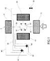
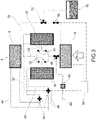
- reference numeral 4 indicates an adsorption refrigeration system aboard a motor vehicle as a whole.
- vehicle is to be understood in a broad sense; in other words, the present invention is easily applied in any type of vehicle.
- the system 4 comprises a condenser 8, adapted to condense a flow of gas or water vapour, an evaporator 12, adapted to generate a gas or water vapour flow, a first adsorbent bed 16 and a second adsorbent bed 20, each containing adsorbent material.
- the type and dimensions of the condenser 8, of the evaporator 12 and of the adsorbent beds 16,20 can be varied, without being restrictive for the purposes of the present invention.
- the adsorbent beds preferably comprise silica-gel and/or zeolites as adsorbent material.
- Each adsorbent bed 16,20 is selectively connectable to the condenser 8 and/or the evaporator 12 by means of pipes or conduits 28 provided with at least one control valve 32.
- the control valves 32 can be of various types, both active and passive.
- said control valves 32 are one-way valves automatically actuated by the pressure and/or depression created by the flows of gas or water vapour from the adsorbent beds in the pipes 28 in which said control valves 32 are inserted.
- This type of passive valve has the advantage of self-adjusting, without requiring a specific drive and/or actuator.
- said control valves 32 are valves selectively operated by actuating means (not shown) to ensure the passage/inhibition of respective flows of water vapour or gas in the respective pipes.
- This embodiment thus provides the use of valves of the active type, so as to have the possibility to guarantee always the correct operation of the valves and possibly to force it, in case of specific system operation requests.
- control valves 32 described above are not mutually alternative or excluding; in other words, a mixed use of said types of control valves 32 is possible within the same system 4.
- control valves The specific operation of the control valves is described in greater detail below.
- each adsorbent bed 16,20 is selectively and alternately connectable to a supply circuit of a heating source 36 and to a supply circuit of a cooling source 40 by means of respective supply valves 44.
- the heating source and the cooling source are typically fluids, i.e. water or coolant, from the engine of the vehicle on which the system 4 is installed. It is also possible to use the heating or cooling fluids in the gaseous state, e.g. the engine exhaust gases for heating and the outside ambient air for cooling.
- the supply circuits of the heating source 36 and of the cooling source 40 typically comprise pipes 48 through which such heating or cooling fluids flow in the liquid or gaseous state.
- the condenser 8 is directly and selectively connectable to the evaporator 12 by a direct branch 52 provided with a respective throttle valve 56.
- the purpose of said throttle valve 56 is to laminate and thus reduce the pressure of the fluid coming from condenser 8 and directed towards evaporator 12, in order to favour its subsequent complete evaporation inside said evaporator 12.
- said system 4 comprises an inlet valve 60 arranged along an air inlet branch 64, adapted to selectively making a fluid connection between the air of the environment outside the system 4 and said adsorbent beds 16,20, so as to capture water from the outside air through an adsorption phenomenon performed by said adsorbent beds 16,20 and to produce water by means of the adsorption phenomenon.
- said inlet valve 60 is a three-way valve able to selectively allow the passage of gas or water vapour from the evaporator 12 towards the adsorbent beds 16, 20 and the passage of external air towards the adsorbent beds 16, 20.
- said air inlet branch 64 is provided with a filter 68.
- said system 4 comprises a bleed valve 72, arranged downstream of the condenser 8 so as to allow condensed water to be bled from said condenser 8.
- said bleed valve 72 is arranged along said direct branch 52, adapted to allow the bleeding of condensed water coming from condenser 8 to evaporator 12.
- said bleed valve 72 is a three-way valve, which selectively allows the direct passage of liquid along the direct branch 52 and the drainage of liquid outside the system 4.
- the bleed valve 72 is connected to a water collection tank 76.
- the present invention consists of an air-cooling system based on an adsorption cycle, appropriately modified so that:
- high outside temperature means a temperature normally above the range of 7°C - 17°C, typically 15°C.
- the "open cycle" adsorption system is used to capture the water contained in the air through the adsorption process by means of the adsorbing beds 16,20.
- one of the two beds e.g. the first adsorbing bed 16
- the adsorption of water from the air is activated, causing a pressure drop which leads to the closing of control valve 32 towards the condenser 8 and the opening of control valve 32 towards inlet valve 60, which, if correctly operated, allows the external air to be introduced through the air inlet branch 64.
- the first adsorbent bed 16 continues to adsorb water from the external air until it reaches saturation.
- the first adsorbing bed 16 is thus heated, thereby activating the water desorption and the consequent pressure increase which leads to the closing of the control valve 32, which connects it to the outside environment through the inlet valve 60 and the air inlet branch 64, and to the opening of the control valve 32 which supplies the condenser 8.
- the vapour produced by heating the first adsorbent bed 16 is then condensed and sent to the water collection tank 76 through the opening of the bleed valve 72.
- one of the two adsorbent beds e.g. the second adsorbent bed 16 is heated with a heat source above 80°C.
- a heat source may be easily available and is, for example, the engine cooling water and/or heat recovered from exhaust gases. It is worth noting that in this manner heat, and therefore thermal energy, which would otherwise be wasted, is recovered: this improves the overall thermal efficiency of the system and the engine of the vehicle on which it is installed.
- the water previously adsorbed by the adsorbing bed is released in form of water vapour and its pressure is increased by closing the control valve 32 connecting to the evaporator 12 and opening the control valve 32 connecting to the condenser 8, which is then supplied by a high-pressure steam flow. Cooling of the vapour occurs in the condenser 8, with the cooling supply circuit 40 at low temperature (preferably below 50°C), consisting of external air or low temperature cooling liquids, which leads to steam condensation.
- low temperature preferably below 50°C
- the condensed water then reaches the evaporator 12 through the throttle valve 56 which lowers the pressure.
- the throttle valve 56 lowers the pressure of the liquid water below a given value, the liquid water goes to the vapour state by removing a quantity of heat equal to its latent vaporizing heat from the outside environment.
- the first adsorbent bed 16 is cooled by means of said cooling supply circuit 40 at low temperature (preferably lower than 50°C), in order to activate the adsorption of the water and therefore the decrease of the pressure which leads to the closing of the control valve 32 towards the condenser 8 and the opening of the one connected to the evaporator 12.
- low temperature preferably lower than 50°C
- the steam generated in the evaporator 12 is adsorbed in the first adsorbent bed 16.
- the first adsorbent bed 16 is completely desorbed, and thus the second adsorbent bed 20 is saturated with water, by means of the supply valves 44, the operation of the two adsorbent beds 16,20 is reversed, thus heating the one which was previously cooled and vice versa cooling the one which was previously heated. In this manner, it is possible to guarantee a practically continuous refrigerating capacity.
- first and second adsorbent bed indicated in the description and in the figures is only indicative and must not be considered in a restrictive sense.
- the water production efficiency depends mainly on environmental conditions (in particular pressure, temperature and relative humidity) and the type of machine (the type of adsorbing material, the temperature of heating and cooling fluids of the adsorbing beds, etc.).
- a given threshold typically between 7 and 17 °C, e.g. 15 °C
- the system is operated as a refrigeration machine and the condensed water is collected near the evaporator 12, if necessary after heating the air in the passenger compartment to ensure passenger comfort.
- a given threshold typically between 7 and 17 °C, e.g. 15 °C
- the system is operated as a refrigeration machine and the condensed water is collected near the evaporator 12, if necessary after heating the air in the passenger compartment to ensure passenger comfort.
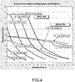
- the adsorbing capacity of the solid matrix decreases with increasing temperature (see Figure 4 )
- the higher thermal gradient between the air and the surface of the evaporator 12 leads to a higher capacity to make water condense from the air.
- the flow rate of water produced will depend on the pressure, temperature and relative humidity of the outside, recirculated air mix.
- the system is made to work in "open circuit" by opening inlet valve 60 and adjusting control valves 32 and supply valves 44.
- the two adsorbent beds 16,20 will work alternately in adsorption and desorption.
- the solid matrix of the adsorbing beds 16,20 is not adsorbed until saturation, but only the time necessary for the complete desorption of the other bed 20,16, because the adsorption rate decreases as the trapped water increases (see Figure 5 ).
- the system When the temperature exceeds the above threshold, or when passengers require cooling of the passenger compartment, the system returns to "closed-circuit" operation by closing the inlet valve 60, closing the bleed valve 72 and moving control valves 32 and the supply valves 44.
- the present invention allows to overcome the drawbacks presented in the prior art.
- the invention allows the production of demineralized water aboard a vehicle in a completely autonomous way, both in high outdoor temperatures and in low outdoor temperatures.
- Such water may be used for injection into the combustion chamber of the internal combustion engine in order to reduce pollutant emissions and/or operating temperature, depending on the type of engine.
- the invention does not require the addition of special components compared to an adsorption air conditioning system and therefore does not imply a significant cost increase compared to a known adsorption system.
- the system according to the present invention is advantageously able to implement the air conditioning of the passenger compartment and the production of demineralized water without the use of a compressor and therefore without taking mechanical energy directly from the internal combustion engine; the production of demineralized water, in particular, is obtained using the thermal power of the combustion engine which is otherwise lost. In this manner, the thermal energy losses from the combustion engine are limited or at least partially recovered and the overall efficiency of the combustion engine is increased.
- an adsorption refrigeration machine allows to remove heat from a low-temperature environment and transfer it to a higher temperature one spending heat instead of mechanical work as in classic compression systems.
- This technology allows to create trigenerative systems, in which, from the waste heat of a car capable of producing mechanical power (i.e. the vehicle traction engine), a heating or refrigerating power is generated.
- mechanical power i.e. the vehicle traction engine
- heating/cooling heat power is used for air conditioning of rooms
- mobile applications in which the mechanical power is typically used directly, or indirectly in the case of series hybrid vehicles, for traction while heat power is used to air-condition the passenger compartment.
- adsorption systems have the advantage of being more compact, of not requiring a circulation pump (with respective energy consumption), of not having the need to contain dangerous water/lithium bromide or water/ammonia liquid solutions and, above all, of not suffering the strong vibrations to which a component mounted on the chassis of a vehicle may be subjected.
- the adsorption consists of the accumulation of molecules of a gas or liquid on the surface of a particular solid, establishing chemical-physical interactions (Wan Der Waals bonds or intermolecular chemical bonds).
- the demineralized water thus produced can also be used for other uses than injection into the combustion chamber; for example, it can be used to top up the cooling system of the engine itself, the tank of the windscreen and/or headlight washer and so on.
Landscapes
- Engineering & Computer Science (AREA)
- Chemical & Material Sciences (AREA)
- Mechanical Engineering (AREA)
- Chemical Kinetics & Catalysis (AREA)
- Oil, Petroleum & Natural Gas (AREA)
- General Chemical & Material Sciences (AREA)
- Analytical Chemistry (AREA)
- Thermal Sciences (AREA)
- Physics & Mathematics (AREA)
- General Engineering & Computer Science (AREA)
- Combustion & Propulsion (AREA)
- Environmental & Geological Engineering (AREA)
- Water Supply & Treatment (AREA)
- Public Health (AREA)
- Hydrology & Water Resources (AREA)
- Life Sciences & Earth Sciences (AREA)
- Health & Medical Sciences (AREA)
- Sorption Type Refrigeration Machines (AREA)
- Separation Of Gases By Adsorption (AREA)
- Air-Conditioning For Vehicles (AREA)
Claims (17)
- Kraftfahrzeug mit einem fahrzeugeigenen Adsorptionskühlsystem (4) zur Erzeugung von entmineralisiertem Wasser, umfassend:- einen Kondensator (8), der geeignet ist, einen Strom von Gas oder Wasserdampf zu kondensieren,- einen Verdampfer (12), der geeignet ist, einen Gas- oder Wasserdampfstrom zu erzeugen,- ein erstes und ein zweites Adsorptionsmittelbett (16, 20), die jeweils Adsorptionsmittel enthalten,- wobei jedes Adsorptionsmittelbett (16, 20) wahlweise mit dem Kondensator (8) und/oder dem Verdampfer (12) über Rohrleitungen (28) verbunden werden kann, die mit wenigstens einem Steuerventil (32) versehen sind,- wobei jedes Adsorptionsmittelbett (16, 20) wahlweise und abwechselnd mit einem Zuführungskreislauf einer Heizquelle (36) und mit einem Zuführungskreislauf einer Kühlquelle (40) mittels Zuführungsventilen (44) verbindbar ist,- wobei der Kondensator (8) über einen direkten Zweig (52), der mit einem entsprechenden Drosselventil (56) versehen ist, direkt und wahlweise mit dem Verdampfer (12) verbindbar ist,dadurch gekennzeichnet, dass- das System (4) ein Einlassventil (60) umfasst, das im Verlauf eines Lufteinlasszweiges (64) angeordnet ist und geeignet ist, wahlweise eine Fluidverbindung zwischen der Umgebungsluft außerhalb des Systems (4) und den Adsorptionsmittelbetten (16, 20) herzustellen, um Wasser aus der Außenluft durch ein Auftreten von Adsorption einzufangen, die von den Adsorptionsmittelbetten (16, 20) durchgeführt wird, und um mittels des Auftretens von Adsorption Wasser zu erzeugen.
- Kraftfahrzeug nach Anspruch 1, wobei das System (4) ein Ablassventil (72) umfasst, das stromabwärts des Kondensators (8) angeordnet ist, um zu ermöglichen, dass kondensiertes Wasser aus dem Kondensator (8) abgelassen wird.
- Kraftfahrzeug nach Anspruch 2, wobei das Ablassventil (72) im Verlauf des direkten Zweiges (52) angeordnet ist und geeignet ist, das Ablassen von aus dem Kondensator (8) stammendem Kondenswasser in Richtung zu dem Verdampfer (12) zu ermöglichen.
- Kraftfahrzeug nach Anspruch 3, wobei das Ablassventil (72) ein Drei-Wege-Ventil ist, das wahlweise das direkte Durchlassen von Flüssigkeit entlang des direkten Zweiges (52) und das Ablassen von Flüssigkeit aus dem System nach außen ermöglicht.
- Kraftfahrzeug nach Anspruch 2, 3 oder 4, wobei das Ablassventil (72) mit einem Wassersammeltank (76) verbunden ist.
- Kraftfahrzeug nach einem der Ansprüche 1 bis 5, wobei wenigstens eines der Steuerventile (32) ein Einwegventil ist, das automatisch durch den Druck und/oder Unterdruck angetrieben wird, der durch die Strömungen von Gas oder Wasserdampf aus den Adsorptionsmittelbetten (16, 20) erzeugt wird, und/oder wobei wenigstens eines der Steuerventile (32) ein Ventil ist, das wahlweise durch Betätigungseinrichtungen betätigt wird, um das Durchlassen / Unterbinden der entsprechenden Wasserdampf- oder Gasströmungen sicherzustellen.
- Kraftfahrzeug nach einem der Ansprüche 1 bis 6, wobei das Einlassventil (60) ein Dreiwegeventil ist, das fähig ist, wahlweise das Durchlassen von Gas oder Wasserdampf von dem Verdampfer (12) in Richtung zu den Adsorptionsmittelbetten (16, 20) und das Durchlassen von Außenluft in Richtung zu den Adsorptionsmittelbetten (16, 20) zu ermöglichen.
- Kraftfahrzeug nach einem der Ansprüche 1 bis 7, wobei das Adsorptionsmittel der Adsorptionsmittelbetten (16, 20) Silikagel und/oder Zeolithe umfasst.
- Kraftfahrzeug nach einem der Ansprüche 1 bis 8, eine Steuereinheit (80) umfassend, wobei die Steuereinheit (80) dazu programmiert ist, die Erzeugung von entmineralisiertem Wasser durch Kondensation der Luft am Verdampfer (12) und/oder durch Adsorption der Feuchtigkeit der Außenluft auf der Grundlage der folgenden Bedingungen zu erlangen:- die mögliche Kühlungsanforderung durch Fahrgäste an Bord des Fahrzeugs,- Temperatur und/oder Feuchtigkeit der Außenluft.
- Kraftfahrzeug nach Anspruch 9, wobei die Steuereinheit (80) dazu programmiert ist, den Betrieb des Kühlsystems zu erzwingen, wobei die Erzeugung von Kondenswasser im Verdampfer (12) bevorzugt wird, wenn die Fahrgäste eine Kühlung des Fahrgastraums anfordern, und/oder wobei die Steuereinheit (80) dazu programmiert ist, in Abwesenheit einer Anforderung zur Kühlung des Fahrgastraums das Verfahren zur Erzeugung von flüssigem Wasser zwischen dem Kondensations- und dem Adsorptionsverfahren zu wählen, je nachdem, welches einen größeren Durchsatz sicherstellt.
- Kraftfahrzeug nach einem der Ansprüche 9 bis 10, wobei die Steuereinheit (80) dazu programmiert ist, die Erzeugung von entmineralisiertem Wasser zu erlangen durch Kondensation der Luft an dem Verdampfer (12) und/oder durch Adsorption der Feuchtigkeit der Außenluft, je nachdem, ob die Außentemperatur über oder unter einem Schwellenwert liegt.
- Kraftfahrzeug nach Anspruch 11, wobei die Steuereinheit (80) so programmiert ist, dass dann, wenn die Außentemperatur unter diesem Schwellenwert liegt, die beiden Adsorptionsmittelbetten (16, 20) abwechselnd zur Adsorption und Desorption veranlasst werden, so dass der festen Grundmasse eines Adsorptionsmittelbettes (16, 20) nicht erlaubt wird, bis zur Sättigung zu adsorbieren, sondern nur so lange, wie es für die vollständige Desorption des anderen Adsorptionsmittelbettes (20, 16) erforderlich ist, und/oder wobei die Steuereinheit (80) so programmiert ist, dass dann, wenn die Außentemperatur über diesem Schwellenwert liegt und/oder wenn die Fahrgäste die Kühlung des Fahrgastraums anfordern, das System (4) in einem "geschlossenen Kreislauf" arbeitet, indem es Kondenswasser an dem Verdampfer (12) erzeugt.
- Verfahren zur Erzeugung von entmineralisiertem Wasser an Bord eines Kraftfahrzeugs, das die folgenden Schritte umfasst:- Bereitstellung eines Kraftfahrzeugs nach einem der Ansprüche 1 bis 12,- Erlangen der Erzeugung von entmineralisiertem Wasser durch Kondensation der Luft an dem Verdampfer (12) und/oder durch Adsorption der Feuchtigkeit der Außenluft auf der Grundlage der folgenden Bedingungen:- die mögliche Kühlungsanforderung durch Fahrgäste an Bord des Fahrzeugs,- Temperatur und/oder Feuchtigkeit der Außenluft.
- Verfahren nach Anspruch 13, wobei vorgesehen ist, den Betrieb des Kühlsystems zu erzwingen, wobei die Erzeugung von Kondenswasser in dem Verdampfer (12) bevorzugt wird, wenn die Fahrgäste eine Kühlung des Fahrgastraums anfordern.
- Verfahren nach einem der Ansprüche 13 bis 14, wobei in Abwesenheit einer Anforderung zur Kühlung des Fahrgastraums das Verfahren zur Erzeugung von flüssigem Wasser zwischen dem Kondensations- und dem Adsorptionsverfahren gewählt wird, je nachdem, welches einen größeren Durchsatz sicherstellt.
- Verfahren nach einem der Ansprüche 13 bis 15, wobei die Erzeugung von entmineralisiertem Wasser durch Kondensation der Luft an dem Verdampfer (12) und/oder durch Adsorption der Feuchtigkeit der Außenluft erlangt wird, je nachdem, ob die Außentemperatur über oder unter einem Schwellenwert liegt.
- Verfahren nach Anspruch 16, wobei dann, wenn die Außentemperatur unter diesem Schwellenwert liegt, die beiden Adsorptionsmittelbetten (16, 20) abwechselnd zur Adsorption und Desorption veranlasst werden, so dass der festen Grundmasse eines Adsorptionsmittelbettes (16, 20) nicht erlaubt wird, bis zur Sättigung zu adsorbieren, sondern nur so lange, wie es für die vollständige Desorption des anderen Adsorptionsmittelbetts (20, 16) erforderlich ist, und/oder wobei dann, wenn die Außentemperatur über diesem Schwellenwert liegt und/oder wenn die Fahrgäste die Kühlung des Fahrgastraums anfordern, das System in einem "geschlossenen Kreislauf" arbeitet, indem es Kondenswasser an dem Verdampfer (12) erzeugt.
Applications Claiming Priority (1)
| Application Number | Priority Date | Filing Date | Title |
|---|---|---|---|
| IT102019000003829A IT201900003829A1 (it) | 2019-03-15 | 2019-03-15 | Impianto frigorifero ad adsorbimento per la produzione di acqua demineralizzata a bordo di un autoveicolo, autoveicolo e metodo di produzione di acqua demineralizzata a bordo di un autoveicolo |
Publications (2)
| Publication Number | Publication Date |
|---|---|
| EP3708238A1 EP3708238A1 (de) | 2020-09-16 |
| EP3708238B1 true EP3708238B1 (de) | 2022-07-27 |
Family
ID=66867672
Family Applications (1)
| Application Number | Title | Priority Date | Filing Date |
|---|---|---|---|
| EP20162309.7A Active EP3708238B1 (de) | 2019-03-15 | 2020-03-11 | System und verfahren zur produktion von demineralisiertem wasser an bord eines motorfahrzeugs mittels adsorption und kühlung |
Country Status (5)
| Country | Link |
|---|---|
| US (1) | US11453271B2 (de) |
| EP (1) | EP3708238B1 (de) |
| JP (1) | JP7474080B2 (de) |
| CN (1) | CN111692776B (de) |
| IT (1) | IT201900003829A1 (de) |
Families Citing this family (2)
| Publication number | Priority date | Publication date | Assignee | Title |
|---|---|---|---|---|
| US11067039B1 (en) * | 2020-05-08 | 2021-07-20 | Saudi Arabian Oil Company | High compression boosting and water generation |
| CN113028675A (zh) * | 2021-03-18 | 2021-06-25 | 上海交通大学 | 一种吸附式制冷系统及其运行方法 |
Family Cites Families (17)
| Publication number | Priority date | Publication date | Assignee | Title |
|---|---|---|---|---|
| US3891410A (en) * | 1973-07-30 | 1975-06-24 | Paul M Hankison | Dehydrating compressed air and gases |
| JPS6014265B2 (ja) * | 1979-03-22 | 1985-04-12 | 三菱電機株式会社 | 造水・空調システム |
| JPH0623628B2 (ja) * | 1987-08-28 | 1994-03-30 | 西淀空調機株式会社 | 吸着式冷凍システムの運転方法 |
| DE3737408A1 (de) * | 1987-11-01 | 1989-05-11 | Schack & Co Rekuperator | Verfahren zur rueckgewinnung des bei der desorption von beladenen sorptionsmaterialien anfallenden desorbats sowie vorrichtung dafuer |
| JP2744714B2 (ja) * | 1991-03-18 | 1998-04-28 | 三菱重工業株式会社 | 吸着式冷却装置 |
| JPH07260285A (ja) * | 1994-03-18 | 1995-10-13 | Nippondenso Co Ltd | 吸着式冷凍装置 |
| KR100197917B1 (ko) * | 1996-07-05 | 1999-06-15 | 최병숙 | 제올라이트와 물을 흡착제와 냉매로 사용한 직화흡착식 냉난방장치 |
| CN1177713A (zh) * | 1996-07-05 | 1998-04-01 | 北京庆东锅炉有限公司 | 直接吸附式制冷暖设备 |
| JP4265067B2 (ja) | 2000-02-07 | 2009-05-20 | 株式会社デンソー | 乗物用空調装置 |
| JP5052486B2 (ja) | 2002-08-15 | 2012-10-17 | 株式会社デンソー | 吸着材 |
| US7384454B2 (en) * | 2005-11-03 | 2008-06-10 | Hamilton Sundstrand Corporation | Combined water-from-air and water-from-exhaust system |
| US8268060B2 (en) * | 2007-10-15 | 2012-09-18 | Green Comfort Systems, Inc. | Dehumidifier system |
| CN102249472B (zh) * | 2011-05-13 | 2012-07-04 | 山东大学 | 一种吸附压缩-多效蒸馏系统 |
| EP2881274B1 (de) * | 2012-08-05 | 2019-06-19 | Yokohama Heat use Technology | Entfeuchtungsvorrichtung für ein fahrzeug |
| DE102013226158A1 (de) * | 2013-12-17 | 2015-06-18 | Robert Bosch Gmbh | Adsorptionskältemaschine, Anordnung und Kraftfahrzeug |
| DE102014116672B4 (de) * | 2014-11-14 | 2016-08-18 | Kaeser Kompressoren Se | Zwischenkühlerbypass |
| US9796240B2 (en) * | 2015-08-12 | 2017-10-24 | Caterpillar Inc. | Engine off vapor compression adsorption cycle |
-
2019
- 2019-03-15 IT IT102019000003829A patent/IT201900003829A1/it unknown
-
2020
- 2020-03-11 EP EP20162309.7A patent/EP3708238B1/de active Active
- 2020-03-13 JP JP2020043660A patent/JP7474080B2/ja active Active
- 2020-03-14 US US16/819,056 patent/US11453271B2/en active Active
- 2020-03-15 CN CN202010178950.9A patent/CN111692776B/zh active Active
Also Published As
| Publication number | Publication date |
|---|---|
| JP7474080B2 (ja) | 2024-04-24 |
| CN111692776B (zh) | 2022-12-27 |
| IT201900003829A1 (it) | 2020-09-15 |
| US11453271B2 (en) | 2022-09-27 |
| US20200290433A1 (en) | 2020-09-17 |
| CN111692776A (zh) | 2020-09-22 |
| EP3708238A1 (de) | 2020-09-16 |
| JP2020146682A (ja) | 2020-09-17 |
Similar Documents
| Publication | Publication Date | Title |
|---|---|---|
| CN109458276B (zh) | 一种混合动力汽车车载油气回收系统及控制方法 | |
| Wang et al. | Design and performance prediction of a novel zeolite–water adsorption air conditioner | |
| CN103026149B (zh) | 用于存储热能以作为车辆中辅助能源的系统和方法 | |
| CN114475161A (zh) | 汽车的热管理系统及汽车 | |
| EP3708238B1 (de) | System und verfahren zur produktion von demineralisiertem wasser an bord eines motorfahrzeugs mittels adsorption und kühlung | |
| CN204605456U (zh) | Lng燃料车用双回路节能制冷系统 | |
| RU137238U1 (ru) | Система климат-контроля автомобиля | |
| JPH1193784A (ja) | 燃料蒸気回収装置 | |
| JP2012127526A (ja) | 吸着式冷凍システム | |
| CN103528260A (zh) | 一种利用汽车尾气余热的汽车空调系统 | |
| KR101514924B1 (ko) | 자동차 내부의 순간 냉방장치와 그에 의한 냉방법 | |
| CN116392924A (zh) | 利用电动汽车电动机冷却液余热直接空气碳捕获系统及方法 | |
| CN115178054A (zh) | 二氧化碳捕集系统和方法 | |
| JP2009097355A (ja) | 車両用蒸発燃料処理装置 | |
| CN107605580B (zh) | 一种车用余热回收与空调制冷复合循环系统及其控制方法 | |
| RU2743472C1 (ru) | Абсорбционный кондиционер автомобиля | |
| CN104442287B (zh) | 一种醇类燃料发动机排气余热空调装置 | |
| CN204630145U (zh) | 一种基于汽车尾气余热利用的吸附式空调装置 | |
| KR101651981B1 (ko) | 흡착식 차량용 공조장치 | |
| CN207261089U (zh) | 一种车用余热回收与空调制冷复合循环系统 | |
| JP2011093338A (ja) | 自動車用暖機装置及び自動車用暖機方法 | |
| CN107560030A (zh) | 吸附储能型空调系统及其控制方法 | |
| RU2832173C1 (ru) | Адсорбционный кондиционер | |
| CN107061062B (zh) | 燃油蒸汽控制系统及控制方法 | |
| JP2014224472A (ja) | 内燃機関の燃料供給装置 |
Legal Events
| Date | Code | Title | Description |
|---|---|---|---|
| PUAI | Public reference made under article 153(3) epc to a published international application that has entered the european phase |
Free format text: ORIGINAL CODE: 0009012 |
|
| STAA | Information on the status of an ep patent application or granted ep patent |
Free format text: STATUS: THE APPLICATION HAS BEEN PUBLISHED |
|
| AK | Designated contracting states |
Kind code of ref document: A1 Designated state(s): AL AT BE BG CH CY CZ DE DK EE ES FI FR GB GR HR HU IE IS IT LI LT LU LV MC MK MT NL NO PL PT RO RS SE SI SK SM TR |
|
| AX | Request for extension of the european patent |
Extension state: BA ME |
|
| STAA | Information on the status of an ep patent application or granted ep patent |
Free format text: STATUS: REQUEST FOR EXAMINATION WAS MADE |
|
| 17P | Request for examination filed |
Effective date: 20210302 |
|
| RBV | Designated contracting states (corrected) |
Designated state(s): AL AT BE BG CH CY CZ DE DK EE ES FI FR GB GR HR HU IE IS IT LI LT LU LV MC MK MT NL NO PL PT RO RS SE SI SK SM TR |
|
| GRAP | Despatch of communication of intention to grant a patent |
Free format text: ORIGINAL CODE: EPIDOSNIGR1 |
|
| STAA | Information on the status of an ep patent application or granted ep patent |
Free format text: STATUS: GRANT OF PATENT IS INTENDED |
|
| INTG | Intention to grant announced |
Effective date: 20220325 |
|
| RIN1 | Information on inventor provided before grant (corrected) |
Inventor name: DE CESARE, MATTEO Inventor name: BRUGNONI, ENRICO |
|
| GRAS | Grant fee paid |
Free format text: ORIGINAL CODE: EPIDOSNIGR3 |
|
| GRAA | (expected) grant |
Free format text: ORIGINAL CODE: 0009210 |
|
| STAA | Information on the status of an ep patent application or granted ep patent |
Free format text: STATUS: THE PATENT HAS BEEN GRANTED |
|
| AK | Designated contracting states |
Kind code of ref document: B1 Designated state(s): AL AT BE BG CH CY CZ DE DK EE ES FI FR GB GR HR HU IE IS IT LI LT LU LV MC MK MT NL NO PL PT RO RS SE SI SK SM TR |
|
| REG | Reference to a national code |
Ref country code: CH Ref legal event code: EP |
|
| REG | Reference to a national code |
Ref country code: AT Ref legal event code: REF Ref document number: 1506700 Country of ref document: AT Kind code of ref document: T Effective date: 20220815 |
|
| REG | Reference to a national code |
Ref country code: DE Ref legal event code: R096 Ref document number: 602020004137 Country of ref document: DE |
|
| REG | Reference to a national code |
Ref country code: IE Ref legal event code: FG4D |
|
| REG | Reference to a national code |
Ref country code: LT Ref legal event code: MG9D |
|
| REG | Reference to a national code |
Ref country code: NL Ref legal event code: MP Effective date: 20220727 |
|
| PG25 | Lapsed in a contracting state [announced via postgrant information from national office to epo] |
Ref country code: SE Free format text: LAPSE BECAUSE OF FAILURE TO SUBMIT A TRANSLATION OF THE DESCRIPTION OR TO PAY THE FEE WITHIN THE PRESCRIBED TIME-LIMIT Effective date: 20220727 Ref country code: RS Free format text: LAPSE BECAUSE OF FAILURE TO SUBMIT A TRANSLATION OF THE DESCRIPTION OR TO PAY THE FEE WITHIN THE PRESCRIBED TIME-LIMIT Effective date: 20220727 Ref country code: PT Free format text: LAPSE BECAUSE OF FAILURE TO SUBMIT A TRANSLATION OF THE DESCRIPTION OR TO PAY THE FEE WITHIN THE PRESCRIBED TIME-LIMIT Effective date: 20221128 Ref country code: NO Free format text: LAPSE BECAUSE OF FAILURE TO SUBMIT A TRANSLATION OF THE DESCRIPTION OR TO PAY THE FEE WITHIN THE PRESCRIBED TIME-LIMIT Effective date: 20221027 Ref country code: NL Free format text: LAPSE BECAUSE OF FAILURE TO SUBMIT A TRANSLATION OF THE DESCRIPTION OR TO PAY THE FEE WITHIN THE PRESCRIBED TIME-LIMIT Effective date: 20220727 Ref country code: LV Free format text: LAPSE BECAUSE OF FAILURE TO SUBMIT A TRANSLATION OF THE DESCRIPTION OR TO PAY THE FEE WITHIN THE PRESCRIBED TIME-LIMIT Effective date: 20220727 Ref country code: LT Free format text: LAPSE BECAUSE OF FAILURE TO SUBMIT A TRANSLATION OF THE DESCRIPTION OR TO PAY THE FEE WITHIN THE PRESCRIBED TIME-LIMIT Effective date: 20220727 Ref country code: FI Free format text: LAPSE BECAUSE OF FAILURE TO SUBMIT A TRANSLATION OF THE DESCRIPTION OR TO PAY THE FEE WITHIN THE PRESCRIBED TIME-LIMIT Effective date: 20220727 Ref country code: ES Free format text: LAPSE BECAUSE OF FAILURE TO SUBMIT A TRANSLATION OF THE DESCRIPTION OR TO PAY THE FEE WITHIN THE PRESCRIBED TIME-LIMIT Effective date: 20220727 |
|
| REG | Reference to a national code |
Ref country code: AT Ref legal event code: MK05 Ref document number: 1506700 Country of ref document: AT Kind code of ref document: T Effective date: 20220727 |
|
| PG25 | Lapsed in a contracting state [announced via postgrant information from national office to epo] |
Ref country code: PL Free format text: LAPSE BECAUSE OF FAILURE TO SUBMIT A TRANSLATION OF THE DESCRIPTION OR TO PAY THE FEE WITHIN THE PRESCRIBED TIME-LIMIT Effective date: 20220727 Ref country code: IS Free format text: LAPSE BECAUSE OF FAILURE TO SUBMIT A TRANSLATION OF THE DESCRIPTION OR TO PAY THE FEE WITHIN THE PRESCRIBED TIME-LIMIT Effective date: 20221127 Ref country code: HR Free format text: LAPSE BECAUSE OF FAILURE TO SUBMIT A TRANSLATION OF THE DESCRIPTION OR TO PAY THE FEE WITHIN THE PRESCRIBED TIME-LIMIT Effective date: 20220727 Ref country code: GR Free format text: LAPSE BECAUSE OF FAILURE TO SUBMIT A TRANSLATION OF THE DESCRIPTION OR TO PAY THE FEE WITHIN THE PRESCRIBED TIME-LIMIT Effective date: 20221028 |
|
| PG25 | Lapsed in a contracting state [announced via postgrant information from national office to epo] |
Ref country code: SM Free format text: LAPSE BECAUSE OF FAILURE TO SUBMIT A TRANSLATION OF THE DESCRIPTION OR TO PAY THE FEE WITHIN THE PRESCRIBED TIME-LIMIT Effective date: 20220727 Ref country code: RO Free format text: LAPSE BECAUSE OF FAILURE TO SUBMIT A TRANSLATION OF THE DESCRIPTION OR TO PAY THE FEE WITHIN THE PRESCRIBED TIME-LIMIT Effective date: 20220727 Ref country code: DK Free format text: LAPSE BECAUSE OF FAILURE TO SUBMIT A TRANSLATION OF THE DESCRIPTION OR TO PAY THE FEE WITHIN THE PRESCRIBED TIME-LIMIT Effective date: 20220727 Ref country code: CZ Free format text: LAPSE BECAUSE OF FAILURE TO SUBMIT A TRANSLATION OF THE DESCRIPTION OR TO PAY THE FEE WITHIN THE PRESCRIBED TIME-LIMIT Effective date: 20220727 Ref country code: AT Free format text: LAPSE BECAUSE OF FAILURE TO SUBMIT A TRANSLATION OF THE DESCRIPTION OR TO PAY THE FEE WITHIN THE PRESCRIBED TIME-LIMIT Effective date: 20220727 |
|
| REG | Reference to a national code |
Ref country code: DE Ref legal event code: R097 Ref document number: 602020004137 Country of ref document: DE |
|
| PG25 | Lapsed in a contracting state [announced via postgrant information from national office to epo] |
Ref country code: SK Free format text: LAPSE BECAUSE OF FAILURE TO SUBMIT A TRANSLATION OF THE DESCRIPTION OR TO PAY THE FEE WITHIN THE PRESCRIBED TIME-LIMIT Effective date: 20220727 Ref country code: EE Free format text: LAPSE BECAUSE OF FAILURE TO SUBMIT A TRANSLATION OF THE DESCRIPTION OR TO PAY THE FEE WITHIN THE PRESCRIBED TIME-LIMIT Effective date: 20220727 |
|
| PLBE | No opposition filed within time limit |
Free format text: ORIGINAL CODE: 0009261 |
|
| STAA | Information on the status of an ep patent application or granted ep patent |
Free format text: STATUS: NO OPPOSITION FILED WITHIN TIME LIMIT |
|
| PG25 | Lapsed in a contracting state [announced via postgrant information from national office to epo] |
Ref country code: AL Free format text: LAPSE BECAUSE OF FAILURE TO SUBMIT A TRANSLATION OF THE DESCRIPTION OR TO PAY THE FEE WITHIN THE PRESCRIBED TIME-LIMIT Effective date: 20220727 |
|
| 26N | No opposition filed |
Effective date: 20230502 |
|
| PG25 | Lapsed in a contracting state [announced via postgrant information from national office to epo] |
Ref country code: SI Free format text: LAPSE BECAUSE OF FAILURE TO SUBMIT A TRANSLATION OF THE DESCRIPTION OR TO PAY THE FEE WITHIN THE PRESCRIBED TIME-LIMIT Effective date: 20220727 |
|
| PG25 | Lapsed in a contracting state [announced via postgrant information from national office to epo] |
Ref country code: MC Free format text: LAPSE BECAUSE OF FAILURE TO SUBMIT A TRANSLATION OF THE DESCRIPTION OR TO PAY THE FEE WITHIN THE PRESCRIBED TIME-LIMIT Effective date: 20220727 |
|
| REG | Reference to a national code |
Ref country code: CH Ref legal event code: PL |
|
| REG | Reference to a national code |
Ref country code: BE Ref legal event code: MM Effective date: 20230331 |
|
| PG25 | Lapsed in a contracting state [announced via postgrant information from national office to epo] |
Ref country code: LU Free format text: LAPSE BECAUSE OF NON-PAYMENT OF DUE FEES Effective date: 20230311 |
|
| REG | Reference to a national code |
Ref country code: IE Ref legal event code: MM4A |
|
| PG25 | Lapsed in a contracting state [announced via postgrant information from national office to epo] |
Ref country code: LI Free format text: LAPSE BECAUSE OF NON-PAYMENT OF DUE FEES Effective date: 20230331 Ref country code: IE Free format text: LAPSE BECAUSE OF NON-PAYMENT OF DUE FEES Effective date: 20230311 Ref country code: CH Free format text: LAPSE BECAUSE OF NON-PAYMENT OF DUE FEES Effective date: 20230331 |
|
| PG25 | Lapsed in a contracting state [announced via postgrant information from national office to epo] |
Ref country code: BE Free format text: LAPSE BECAUSE OF NON-PAYMENT OF DUE FEES Effective date: 20230331 |
|
| PG25 | Lapsed in a contracting state [announced via postgrant information from national office to epo] |
Ref country code: BG Free format text: LAPSE BECAUSE OF FAILURE TO SUBMIT A TRANSLATION OF THE DESCRIPTION OR TO PAY THE FEE WITHIN THE PRESCRIBED TIME-LIMIT Effective date: 20220727 |
|
| GBPC | Gb: european patent ceased through non-payment of renewal fee |
Effective date: 20240311 |
|
| PG25 | Lapsed in a contracting state [announced via postgrant information from national office to epo] |
Ref country code: BG Free format text: LAPSE BECAUSE OF FAILURE TO SUBMIT A TRANSLATION OF THE DESCRIPTION OR TO PAY THE FEE WITHIN THE PRESCRIBED TIME-LIMIT Effective date: 20220727 |
|
| PG25 | Lapsed in a contracting state [announced via postgrant information from national office to epo] |
Ref country code: GB Free format text: LAPSE BECAUSE OF NON-PAYMENT OF DUE FEES Effective date: 20240311 |
|
| PG25 | Lapsed in a contracting state [announced via postgrant information from national office to epo] |
Ref country code: GB Free format text: LAPSE BECAUSE OF NON-PAYMENT OF DUE FEES Effective date: 20240311 |
|
| PG25 | Lapsed in a contracting state [announced via postgrant information from national office to epo] |
Ref country code: CY Free format text: LAPSE BECAUSE OF FAILURE TO SUBMIT A TRANSLATION OF THE DESCRIPTION OR TO PAY THE FEE WITHIN THE PRESCRIBED TIME-LIMIT; INVALID AB INITIO Effective date: 20200311 |
|
| PG25 | Lapsed in a contracting state [announced via postgrant information from national office to epo] |
Ref country code: HU Free format text: LAPSE BECAUSE OF FAILURE TO SUBMIT A TRANSLATION OF THE DESCRIPTION OR TO PAY THE FEE WITHIN THE PRESCRIBED TIME-LIMIT; INVALID AB INITIO Effective date: 20200311 |
|
| PG25 | Lapsed in a contracting state [announced via postgrant information from national office to epo] |
Ref country code: TR Free format text: LAPSE BECAUSE OF FAILURE TO SUBMIT A TRANSLATION OF THE DESCRIPTION OR TO PAY THE FEE WITHIN THE PRESCRIBED TIME-LIMIT Effective date: 20220727 |
|
| PGFP | Annual fee paid to national office [announced via postgrant information from national office to epo] |
Ref country code: DE Payment date: 20260219 Year of fee payment: 7 |
|
| PGFP | Annual fee paid to national office [announced via postgrant information from national office to epo] |
Ref country code: IT Payment date: 20260219 Year of fee payment: 7 |
|
| PGFP | Annual fee paid to national office [announced via postgrant information from national office to epo] |
Ref country code: FR Payment date: 20260220 Year of fee payment: 7 |