EP3708230A1 - Haltevorrichtung für gleitbrette - Google Patents
Haltevorrichtung für gleitbrette Download PDFInfo
- Publication number
- EP3708230A1 EP3708230A1 EP20162182.8A EP20162182A EP3708230A1 EP 3708230 A1 EP3708230 A1 EP 3708230A1 EP 20162182 A EP20162182 A EP 20162182A EP 3708230 A1 EP3708230 A1 EP 3708230A1
- Authority
- EP
- European Patent Office
- Prior art keywords
- frame
- relief
- rack
- reliefs
- complementary
- Prior art date
- Legal status (The legal status is an assumption and is not a legal conclusion. Google has not performed a legal analysis and makes no representation as to the accuracy of the status listed.)
- Granted
Links
Images


Classifications
-
- A—HUMAN NECESSITIES
- A63—SPORTS; GAMES; AMUSEMENTS
- A63C—SKATES; SKIS; ROLLER SKATES; DESIGN OR LAYOUT OF COURTS, RINKS OR THE LIKE
- A63C9/00—Ski bindings
- A63C9/08—Ski bindings yieldable or self-releasing in the event of an accident, i.e. safety bindings
- A63C9/086—Ski bindings yieldable or self-releasing in the event of an accident, i.e. safety bindings using parts which are fixed on the shoe of the user and are releasable from the ski binding
-
- A—HUMAN NECESSITIES
- A63—SPORTS; GAMES; AMUSEMENTS
- A63C—SKATES; SKIS; ROLLER SKATES; DESIGN OR LAYOUT OF COURTS, RINKS OR THE LIKE
- A63C5/00—Skis or snowboards
- A63C5/12—Making thereof; Selection of particular materials
- A63C5/128—A part for the binding being integrated within the board structure, e.g. plate, rail, insert
-
- A—HUMAN NECESSITIES
- A63—SPORTS; GAMES; AMUSEMENTS
- A63C—SKATES; SKIS; ROLLER SKATES; DESIGN OR LAYOUT OF COURTS, RINKS OR THE LIKE
- A63C9/00—Ski bindings
- A63C9/003—Non-swivel sole plate fixed on the ski
-
- A—HUMAN NECESSITIES
- A63—SPORTS; GAMES; AMUSEMENTS
- A63C—SKATES; SKIS; ROLLER SKATES; DESIGN OR LAYOUT OF COURTS, RINKS OR THE LIKE
- A63C9/00—Ski bindings
- A63C9/005—Ski bindings with means for adjusting the position of a shoe holder or of the complete binding relative to the ski
-
- A—HUMAN NECESSITIES
- A63—SPORTS; GAMES; AMUSEMENTS
- A63C—SKATES; SKIS; ROLLER SKATES; DESIGN OR LAYOUT OF COURTS, RINKS OR THE LIKE
- A63C9/00—Ski bindings
- A63C9/08—Ski bindings yieldable or self-releasing in the event of an accident, i.e. safety bindings
- A63C9/0807—Ski bindings yieldable or self-releasing in the event of an accident, i.e. safety bindings for both towing and downhill skiing
-
- A—HUMAN NECESSITIES
- A63—SPORTS; GAMES; AMUSEMENTS
- A63C—SKATES; SKIS; ROLLER SKATES; DESIGN OR LAYOUT OF COURTS, RINKS OR THE LIKE
- A63C9/00—Ski bindings
- A63C9/20—Non-self-releasing bindings with special sole edge holders instead of toe-straps
-
- F—MECHANICAL ENGINEERING; LIGHTING; HEATING; WEAPONS; BLASTING
- F16—ENGINEERING ELEMENTS AND UNITS; GENERAL MEASURES FOR PRODUCING AND MAINTAINING EFFECTIVE FUNCTIONING OF MACHINES OR INSTALLATIONS; THERMAL INSULATION IN GENERAL
- F16H—GEARING
- F16H25/00—Gearings comprising primarily only cams, cam-followers and screw-and-nut mechanisms
- F16H25/18—Gearings comprising primarily only cams, cam-followers and screw-and-nut mechanisms for conveying or interconverting oscillating or reciprocating motions
- F16H25/20—Screw mechanisms
- F16H25/2015—Means specially adapted for stopping actuators in the end position; Position sensing means
-
- A—HUMAN NECESSITIES
- A63—SPORTS; GAMES; AMUSEMENTS
- A63C—SKATES; SKIS; ROLLER SKATES; DESIGN OR LAYOUT OF COURTS, RINKS OR THE LIKE
- A63C9/00—Ski bindings
- A63C2009/008—Ski bindings with a binding element sliding along a rail during use or setting
Definitions
- the invention relates to the field of devices for retaining a boot on a gliding board. It relates more particularly to retaining devices which allow longitudinal adjustment of the position of the boot on the gliding board. It finds a particularly advantageous application in cross-country skiing.
- the retaining device comprises a frame carrying a mechanism for hooking an element belonging to the boot, the frame also carrying an adjustment member. When the user actuates the adjustment member, the frame moves longitudinally on the gliding board, while the boot remains in engagement with the retaining device.
- An object of the present invention is therefore to provide a retaining device making it possible to limit, or even eliminate, at least one of the drawbacks mentioned above.
- the adjustment member comprises a cooperation portion mounted in rotation about an axis of rotation inclined at an angle ⁇ of between 30 ° and 90 ° relative to said main plane (XY) in which mainly extends the lower face. of the chassis, the cooperation portion comprising a lower face bearing at least a first relief.
- the at least one first relief has at least two lateral flanks extending respectively along a curved trajectory shaped so that the distance between a point of one of these trajectories and said axis of rotation varies progressively throughout minus part of the curved path.
- the first relief is configured so that its lateral flanks are able to cooperate with contact surfaces of complementary reliefs of the rack so as to cause the longitudinal sliding of the frame relative to the gliding board under the effect of the rotation of the rack. the cooperation portion around said axis.
- control member is easily accessible. This allows the user to adjust the longitudinal position of his shoe easily and quickly, thereby leading to improved sports performance and comfort.
- this construction allows a particularly compact integration of the adjustment member in the binding. This allows in particular a good balance of the gliding board.
- the weight of the adjustment mechanism can be located near the shoe's holding mechanism.
- the adjustment mechanism is positioned towards the front of the gliding board and at a variable distance from the holding mechanism of the boot, which tends to unbalance the gliding board.
- the adjustment member is little exposed. This leads to reducing the risks of unintentional handling by external elements which can interfere with the restraint device during sliding.
- external elements can for example be another gliding board, typically the user's other ski, roots, safety nets, etc.
- this construction makes it possible to protect the cooperation portion of the adjustment member from the external environment (snow, frost).
- the solution allows adjustment of the longitudinal position of the boot while the latter remains in engagement with the holding mechanism.
- this solution makes it possible to adjust the longitudinal position of the boot over a long stroke length.
- the invention thus offers an improved amplitude of adjustment compared to solutions in which a rack with straight teeth would be driven by a pinion in rotation about a horizontal axis transverse to that of the gliding board.
- the invention provides a retaining device adaptable to a multitude of gliding boards requiring few interfacing elements with the retaining device.
- the retaining device can be mounted directly on the gliding board or on a single intermediate piece, an interface plate, integral with the gliding board.
- a user may prefer one pair of skis over another. Thanks to the invention, he can easily remove the retaining device from a first pair of skis for use on a second pair of skis by handling only very few parts: the retaining device and the gliding board, equipped or not with an interface plate. This is made possible by the fact that the adjusting member making it possible to modify the longitudinal position of the boot is carried, preferably entirely, by the latter's retaining device.
- the rack is formed by an upper face of the gliding board itself.
- the rack is formed by an interface plate which is attached to an upper face of the gliding board. This second embodiment makes it possible to very easily adapt a gliding board so that it becomes compatible with the retaining device according to the invention.
- the invention may further have at least any one of the following characteristics: According to one example, the axis of rotation is included in a median longitudinal plane of the frame.
- the cooperation portion comprises at least one second relief having two lateral flanks respectively extending along a curved path shaped so that the distance between a point of one of the paths of the lateral flanks of the second relief and said axis of rotation gradually varies along at least part of this curved path.
- the two lateral flanks of the second relief are angularly offset with respect to the lateral flanks of the first relief.
- the relief has a curved shape, such as a portion of a spiral, which extends at an angle greater than 180 °.
- the relief has a curved shape, such as a portion of a spiral, which extends at an angle of less than 360 °. This makes it possible to limit the size of the adjustment mechanism. The balance of the gliding board is improved.
- the adjustment member comprises at least one indexing element able to cooperate with a complementary indexing element integral with the frame so as to maintain the cooperation portion in at least one stable angular position.
- the adjustment of the longitudinal position of the shoe is thus made more intuitive, quick and easy. This leads to improving the performance of the skier. Moreover, this makes it possible to reduce, or even avoid, the risks of involuntary manipulation of the adjustment member.
- the at least one stable angular position corresponds to the sliding configuration.
- the cooperation portion is dimensioned and arranged so that when a first portion of the first relief is able to engage with at least one complementary relief of the rack, a second portion of the first relief, arranged in opposition by relative to the axis of rotation, is no longer able to cooperate with at least one complementary relief of the rack.
- the lower face of the cooperation portion is conical.
- the adjustment member comprises a control member configured to be manipulated by the user in order to drive the cooperation portion in rotation around the axis of rotation.
- the frame has an upper part and a lower housing intended to be rotated with respect to the rack, the cooperation portion being housed in said lower housing.
- the retainer includes a control member configured to be manipulated by the user to rotate the cooperating portion about the axis of rotation.
- the control member is positioned above the upper part of the chassis to be accessible manually by the user.
- cooperation portion is housed inside the housing defined by the frame protects the latter from impact and weathering. In particular, this makes it possible to prevent frost or the accumulation of snow from blocking the cooperation of the reliefs such as ribs with the rack.
- the holding mechanism comprises an actuation lever articulated in rotation on the frame, defining a contour, the lever being manipulable by the user between a retention configuration for which the holding mechanism retains the boot and a configuration release for which the holding mechanism authorizes the release of the shoe from the device retainer, the control member being dimensioned and arranged so as to be located above the lever when the latter is in the retention configuration and so as to be able to pass through said contour when passing through the retention configuration to the release configuration.
- the actuating lever has at least two branches extending mainly longitudinally. This embodiment also makes it possible to protect the adjustment mechanism against impacts.
- said main plane in which the lower face of the chassis mainly extends corresponds to a plane parallel to the sliding plane of the gliding board.
- the main plane is substantially horizontal.
- the cooperation portion forms a disc.
- the holding mechanism comprises a jaw movable between an engagement position for which the movable jaw is able to cooperate with the hooking element so as to allow the attachment of the hooking element with the device.
- retainer while allowing rotation of the boot about an axis transverse to the retainer, and a release position for which the movable jaw is in a configuration allowing the separation of the fastening element from the retainer .
- An actuator such as a lever controls a movement of the movable jaw to make it tilt from the engagement position to the release position.
- Another aspect of the present invention relates to an interface plate, extending mainly along a longitudinal axis, and comprising a rack. having complementary reliefs distributed parallel to said longitudinal axis of the interface plate.
- Each complementary relief has at least two curved contact surfaces configured to cooperate with contact surfaces carried by at least one first relief carried by a cooperation portion of a frame of a retaining device for a sliding shoe.
- the at least one first relief has at least two lateral flanks extending respectively along a curved trajectory shaped so that the distance between a point of one of these trajectories and an axis of rotation around which the portion is mounted in rotation. cooperation varies progressively along at least a part of the curved path, so that the rotation of the cooperation portion about its axis of rotation causes the longitudinal sliding of the frame along said longitudinal axis of the interface plate.
- Another aspect of the present invention relates to an interface plate suitable for fixing to a gliding board, and comprising at least one rack configured to cooperate with the adjustment member of a retaining device according to the invention.
- the interface plate extends mainly along a longitudinal axis, the rack having reliefs of which at least one surface is curved.
- these complementary reliefs include at least one curved contact surface.
- the interface plate extends mainly along a longitudinal axis, the rack having reliefs whose alignment is off-center relative to said longitudinal axis of the interface plate. This has the advantage of facilitating longitudinal movement with the adjustment member described above.
- the interface plate comprises complementary reliefs carried by the rack, the complementary reliefs having an asymmetric shape with respect to the longitudinal axis of the interface plate.
- the rack is provided on one of the gliding board and on an interface plate.
- the interface plate can be glued or screwed onto the gliding board.
- the complementary retaining element is formed by one of: the gliding board and an interface plate integral with the gliding board.
- the rack is carried by the complementary retaining element.
- Another aspect of the present invention relates to an assembly comprising a retaining device according to the invention and an interface plate according to the invention.
- Another aspect of the present invention relates to a gliding board equipped with a retaining device according to the invention.
- the gliding board comprises a rack formed by one face of the gliding board.
- the gliding board includes a interface plate, attached to one face of the gliding board and forming at least one of the rack and the complementary retaining element.
- rack designates a mechanical device having complementary reliefs able to cooperate with reliefs of a drive part so that, when the drive part is handled, this cooperation causes the translation of the drive part.
- complementary reliefs or notches are distributed in a substantially linear manner.
- the term “on”, “overcomes” or “underlying” or their equivalents do not necessarily mean “in contact with”.
- first part is placed on a second part, this does not necessarily mean that the two parts are directly in contact with one another, but it means that the first part at least partially covers the second part in being either directly in contact with it or by being separated from it by another part or another element.
- the term “integral” used to qualify the connection between two parts means that the two parts are linked / fixed with respect to each other, according to all the degrees of freedom unless it is explicitly specified differently. For example, if it is indicated that two parts are integral in translation in an X direction, this means that the parts can be mobile, possibly according to several degrees of freedom, to the exclusion of the freedom in translation in the X direction. In other words, if we move a part in the X direction, the other part performs the same movement.
- the main objectives of the invention are the compactness of the binding and its weight reduction, mainly for cross-country skiing or hiking.
- the invention thus makes it possible to take full advantage of the intrinsic performance of the gliding board by having a very good distribution of masses. It is important to avoid a center of gravity positioned too far forward, in particular in front of the axis of rotation of the boot relative to the ski board. In fact, if this is the case, the risk of planting the front tip of the ski board in the snow during propulsion movements is increased.
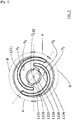
- the figure 1 in particular illustrates a gliding board 20 equipped with a retaining device 10, usually designated by the term “binding”, for a gliding boot (not shown in the figures).
- the gliding board 20 has an upper face 21 facing the retaining device 10 and a lower face 22 intended to come into contact with the substrate, typically snow.
- the lower face 22 thus defines a surface and a sliding plane.
- the sliding plane corresponds to the XY plane of the XYZ orthogonal coordinate system illustrated in figure 1 .
- the retaining device 10 comprises a frame 100 carrying a retaining mechanism 110 for a sliding boot.
- the retention mechanism 110 selectively allows the shoe to be engaged with the retaining device 10 or to release the boot from the retaining device 10.
- the boot can be completely fixed with respect to the retaining device 10. This is for example the case downhill skiing.
- the holding mechanism 110 allows the boot to retain one or more degrees of freedom.
- the boot is articulated in rotation on the retaining device 10 about a horizontal axis transverse to the sliding direction, at the toes.
- the example shown in figure 1 applies, for example, to cross-country skiing.
- the boot then comprises an attachment element, typically a shaft extending in a direction substantially transverse Y to the main longitudinal direction X of the gliding board, when the boot is engaged with the holding mechanism.
- the hooking element is integrated in a recess in the front of the sole of the shoe.
- the shoe can, for example, comply with the technical teaching of the requests EP-A-0 913 102 and or EP-A-0 913 103 which we can refer to for more details.
- the retaining mechanism 110 comprises a fixed jaw 112, a movable jaw 113, an actuator 114 and a movement transformation device 115.
- the actuator 114 such as a lever, controls a movement of the movable jaw 113 to selectively move it from the engagement position to the release position and vice versa.
- the transmission of the movement between the actuator 114 and the movable jaw 113 is ensured by the movement transformation device 115.
- Elements of this movement transformation device 115 are illustrated in figure 2 . They include, in this example, connecting rods 1151, pins 1152 connecting a first end of connecting rods 1151 with the actuator 114, a pin 1153 connecting a second end of connecting rods 1151 with the frame 100 and pins 1154 connecting the actuator 114 with the movable jaw 113.
- the figure 2 also makes visible the arrangements made on the frame 100, namely, a through hole 1156 for the passage of the pin 1153 and oblong holes 1157 for the passage of the pin 1154.
- the movable jaw includes holes 1132 for the passage of a pin 1154.
- the retaining device 10 also comprises an elastic part 130 against which the front of the sliding boot is intended to come into contact.
- This elastic part 130 is usually referred to as a “flexor”.
- An adjustment mechanism 120 carried in part by the frame 100, enables the frame 100 to be moved longitudinally relative to the gliding board 20.
- the adjustment mechanism 120 comprises a rack 32 integral with the gliding board 20. and an adjustment member 1200 configured to cooperate with the rack 32.
- the adjustment member 1200 comprises a control member 121, a cooperation portion 122 and, optionally, a movement transmission device 123.
- the adjustment member 1200 When the adjustment member 1200 is actuated, it causes the longitudinal sliding of the frame 100 relative to the gliding board 20.
- the boot being retained by the holding mechanism 110 carried by the frame 100, it is also driven in translation and the user can adjust its longitudinal position relative to the gliding board.
- the frame 100 has a median longitudinal axis, parallel to the X direction, and comprises two profiles, located on either side of this median longitudinal axis. Each of these profiles form an emerging longitudinal groove 106, transversely, in the direction of the median longitudinal axis. These two grooves, facing each other, are intended to receive respectively a guide rail 31 carried by a complementary retaining element integral with the gliding board 20. These grooves each form a slide 101. Each of these slides 101 is thus guided in translation by the rail 31.
- the complementarity of the frame 100 and the complementary retaining element in addition to providing a translational guiding function, prevents a distance of the frame 100 from the gliding board 20 in the Z direction.
- the kinematic connection formed by each slide 101 and its complementary rail 31 is a sliding connection, that is to say a connection with a single degree of freedom corresponding to the sliding of the frame 100 according to direction X.
- the rails 31 of the additional retaining element are carried by an interface plate 30 integral with the gliding board 20.
- the interface plate 30 is attached to the gliding board 20.
- a lower face 38 of the interface plate 30 is placed directly in contact with the upper face 21 of the gliding board 20.
- the interface plate 30 is for example glued or screwed onto the gliding board 20.
- the sliding board 20 forms the rails 31 for guiding and retaining.
- the complementary retaining element carrying the rails 31 is formed directly by the gliding board 20.
- the frame 100 may have a lower face 103 provided with additional slides 104.
- These additional slides 104 are shaped to cooperate with complementary grooves 35 integral with the gliding board 20.
- these grooves Complementary 35 are carried by the interface plate 30.
- these complementary grooves 35 can be formed directly by the gliding board 20.
- these complementary grooves 35 extend in a direction parallel to the 'X axis.
- the rack 32 of the adjustment mechanism appears more distinctly on the figures 2 , 3 , 4 , and 5 .
- the rack 32 has several complementary reliefs 321.
- these complementary reliefs 321 each have at least one curved contact surface Y1, Y2 capable of cooperating with at least one lateral flank X1, X2 of a relief 1221, 1222 driven by the adjustment member 1200.
- each complementary relief 321 is delimited by two curved contact surfaces whose edges meet.
- Each complementary relief 321 has the shape of a portion of the moon.
- Other forms of complementary relief are perfectly conceivable.
- the complementary reliefs 321 can form portions of truncated moons, or pads, as will be described with reference to figures 9 and 10 .
- the adjuster 1200 of the adjuster 120 appears more distinctly on the figures 2 , 3 , 6 and 7 .
- the adjustment member 1200 comprises a cooperation portion 122, for example having the shape of a disc and bearing at least one relief 1221, 1222.
- the cooperation portion 122 has a lower face 1226 bearing two reliefs 1221, 1222. This number of reliefs is not limiting. These two reliefs 1221, 1222 appear in figure 6 and 7 .
- the adjustment mechanism 120 is shaped so that the actuation of the adjustment member 1200 causes the rotation of the cooperation portion 122 about an axis of rotation z122.
- the relief (s) 1221, 1222 carried by the cooperation portion 122 have two lateral flanks X1, X2 extending respectively along a curved path shaped so that the distance between a point of one of these paths and said axis of rotation z122 of the cooperation portion 122 gradually varies when one traverses part of the curved path.
- the lateral flanks X1, X2 are shaped to cooperate with the contact surfaces Y1, Y2 of the complementary reliefs 321 carried by the rack 32 so as to cause the longitudinal sliding of the frame 100 relative to the gliding board 20 under the effect of the rotation of the cooperation portion 122 about said axis of rotation z122.
- the relief (s) 1221, 1222 carried by the cooperation portion 122 each form a projection, typically on the lower face 1226 of the cooperation portion 122.
- Each relief 1221, 1222 forms a rib. It is this embodiment which is illustrated in the figures. According to an alternative example, these reliefs are hollow. The following description describes the illustrated embodiment having ribs. Nevertheless, each characteristics and advantages mentioned above are perfectly applicable to the embodiments with hollow reliefs.
- the relief (s) 1221, 1222 carried by the cooperation portion 122 can each form a spiral portion. Consequently, the lateral flanks X1, X2 can also each form a portion of a spiral.
- a spiral or portion of a spiral is a curve which evolves around an axis away from the latter.
- this axis corresponds to the axis of rotation z122 of the cooperation portion 122 and passes through the center 1220 of the spiral.
- the spiral has a constant pitch.
- the figure 7 illustrates an embodiment in which the rib has a constant pitch.
- the axis of rotation z122 of the cooperation portion 122 is inclined at an angle ⁇ relative to the main plane in which the lower face 103 of the frame 100 extends. This plane is substantially parallel to the XY plane and to the sliding plane. of the board slides 20.
- the angle ⁇ is between 30 ° and 90 °.
- the axis of rotation z122 is included in a median longitudinal plane of the frame 100, this median longitudinal plane being parallel to the plane ZX.
- the adjustment member 1200 comprises a control member 121 which can be manipulated by the user in order to drive the cooperation portion 122 in rotation about its axis z122.
- control member 121 is a rotation of the control member 121 which causes the rotation of the cooperation portion 122 about its axis z122.
- the control member 121 can be fixed with respect to the cooperation portion 122, that is to say that it has no degree of freedom with respect to the latter.
- the control member 121 drives the cooperation portion 122 in rotation by means of a device 123 for transmitting movements which will be described in more detail below.
- control member 121 When the control member 121 is driven in rotation, it drives the cooperation portion 122 in rotation around the axis z122.
- the at least one relief 1221, 1222 of the cooperation portion 122 for example each forming a spiral portion, cooperates or engages with the complementary reliefs 321 of the rack 32 which causes the sliding of the frame 100.
- the cooperation portion 122 comprises two reliefs 1221, 1222, here two ribs. Each of these reliefs forms a portion of a spiral centered on the axis of rotation z122. Preferably these two portions of the spiral have the same pitch. These two spiral portions are angularly offset. Thus, for a given angle their radial position is different.
- each of these two reliefs 1221, 1222 of the cooperation portion 122 has two lateral flanks X1, X2 respectively extending along a curved path shaped so that the distance between a point of one of the trajectories of the lateral flanks X1, X2 of a relief 1221, 1222 and said axis of rotation z122 varies progressively along at least part of this curved trajectory.
- the two lateral flanks of the second relief 1222 are angularly offset with respect to the lateral flanks of the first relief 1221.
- This construction makes it possible to have, for certain angular positions of the cooperation portion 122, the two reliefs 1221, 1222 which simultaneously cooperate with several complementary reliefs 321 of the rack 32.
- This configuration is illustrated in figure 3 .
- the portions of spiral 1221 ', 1222' are simultaneously engaged with the complementary reliefs 321 '. This allows better transmission of forces in a longitudinal direction X, between the binding and the gliding board, in particular during the phases of propulsion of the skier.
- each of the two reliefs 1221, 1222 does not necessarily extend over a great length.
- each relief 1221, 1222 in this example each portion of a spiral, extends over an angular sector less than 360 ° and preferably less than 180 °. This makes it possible to considerably limit the radial extension of the cooperation portion 122. If the latter has the shape of a disc, then the presence of at least two spiral portions makes it possible to reduce its diameter.
- an embodiment with several reliefs 1221, 1222, typically several portions of shorter spirals, extending over an angle less than 360 °, is more advantageous than an embodiment which would have only one relief 1221 , 1222, typically only a single spiral, extending over a portion greater than 360 °.
- the cooperation portion 122 would have a necessarily larger diameter.
- the embodiment with several portions of spirals thus makes it possible to make the adjustment mechanism 120 more compact by substantially reducing its bulk. This thus makes it possible to better integrate the binding on the gliding board 20 and in particular to design a relatively narrow frame 100 whose width is less than the width of the gliding board 20.
- the retaining device 10 also referred to as binding, does not extend much or not beyond the lateral edges of the ski. This avoids the risk of contact or injury with the frame 100, hindrance in the movements of the skier or even damage the frame 100. This therefore increases the strength of the binding and therefore its reliability. By being more compact, this also allows the center of gravity of the binding to be moved backwards, which contributes to better ski balance.
- the adjustment member 1200 is configured so that the cooperation portion 122 can be positioned angularly, around said axis z122, according to at least two configurations among which: a sliding configuration for which the at least two reliefs 1221, 1222 are able to be simultaneously engaged with the rack 32 and a transient adjustment configuration for which only one of the reliefs is able to engage with rack 32.
- the sliding configuration corresponds to the configuration for which at least the first and the second reliefs 1221, 1222 are able to be simultaneously engaged with at least one of the complementary reliefs 321 of the rack 32 and the adjustment configuration transient corresponds to the configuration for which only some and preferably only one of the at least two reliefs 1221, 1222 are able to engage with at least one of the complementary reliefs 321 of the rack 32.
- This feature makes it possible to reinforce the robustness in the sliding configuration since two reliefs are engaged in this configuration, while limiting the size of the adjustment mechanism 120, due to the fact that a single relief is in engagement with the rack 32 in this configuration. transient adjustment.
- the size of the adjustment mechanism 120 is further reduced and the balancing of the gliding board 20 is further improved.
- this also makes it possible to optimize the weight of the binding.
- the relief is dimensioned so that, only in the sliding configurations, there is sufficient material, with two reliefs engaged, to transmit the longitudinal forces.
- the number of reliefs in engagement is reduced, with a single relief in engagement. The material is then minimized, which saves the weight of the sliding device.
- each relief 1221, 1222 typically each spiral or portion of a spiral, extends over approximately an angular sector of between 200 ° and 240 °.
- the two reliefs 1221, 1222 are arranged so as to have two overlapping zones A, each corresponding to an angular sector in which a radius starting from the center 1220 meets each of the reliefs 1221, 1222.
- These two overlapping zones A are arranged symmetrically with on either side of the center 1220.
- the other angular sectors correspond to non-overlapping zones B, illustrated in figure 7 .
- the cooperation portion 122 is angularly positioned so as to engage the or one of the overlapping zones A with the rack 32 It follows that the two reliefs 1221, 1222 are then engaged with complementary reliefs 321 of the rack 32.
- the cooperation portion 122 is angularly positioned so as to engage a non-overlapping zone B with the rack 32. It s' It follows that only one of the two reliefs 1221, 1222 is then engaged with complementary reliefs 321 of the rack 32.
- the adjustment mechanism comprises an indexing device configured to maintain the control member 121 in a position of stable equilibrium when the latter is in the sliding configuration.
- an involuntary activation of the control member 121 is avoided when the latter is in the sliding configuration.
- the indexing device is configured so that the control member 121 is in an unstable equilibrium position in the transient adjustment configuration.
- the indexing device may comprise an elastic means making it possible to return the control member 121 to a stable position.
- the control member 121 has a tendency to automatically return to the sliding configuration in the event of unintentional manipulation of the latter or if the user forgets to bring it back to the sliding configuration.
- the indexing device also makes it safer, more intuitive, quick and easy to adjust the longitudinal position of the shoe. This leads to shortening the adjustment time and therefore to improving the performance of the skier.
- the indexing device comprises a first indexing element carried by the adjustment member 1200 as well as a complementary indexing element integral with the frame 100.
- the complementary indexing element may be integral with the plank of glide 20. According to one embodiment, it can also be supported by an intermediate part, such as an interface plate 30, fixed to the gliding board 20.
- the first indexing element is a raised area, for example a hollow 1227, carried by an upper face 1225 of the cooperation portion 122, this upper face 1225 being a face opposite to the lower face 1226 bearing the reliefs 1221, 1222.
- the cooperation portion 122 comprises a first indexing element for each of the angular sectors corresponding to a sliding configuration.
- the cooperation portion 122 has a raised zone, here a hollow 1227, in line with each of the overlapping zones 1223.
- the complementary indexing element is for example carried by a face of the frame facing the cooperation portion 122 and which has a complementary relief, for example a projecting relief 1241.
- This complementary projecting relief is for example carried by a elastic tongue 1242.
- the complementary relief is formed by an indexing part 124 carried by or integral with the frame 100.
- the frame 100 forms a housing 105 opening onto its lower face 103.
- the cooperation portion 122 is located inside this housing 105 so as to be confined inside the frame 100. while being able to cooperate with the rack 32 located opposite the underside 103 of the frame 100.
- the cooperation portion 122 carrying the reliefs 1221, 1222 is protected by the frame 100. This makes it possible to protect the cooperation portion 122 from bad weather such as the accumulation of snow or frost which could block its cooperation with the rack 32 and to protect it from shocks.
- the reliability of the adjustment mechanism 120 is thereby enhanced.
- the frame 100 also has an upper part 102.
- the control member 121 is positioned above the upper part 102 so as to be accessible, preferably manually, by the user.
- the cooperation portion 122 is dimensioned and arranged so that when a first portion of a spiral is able to engage with the rack 32, a second portion of this same spiral, disposed in opposition with respect to the axis of rotation z122 is no longer able to cooperate with the rack 32.
- the cooperation portion 122 is dimensioned and arranged so that when a first portion of the first relief 1221 is able to engage with at least one complementary relief 321 of the rack 32, a second portion of the first relief 1221, symmetrically disposed with respect to said axis of rotation z122, is no longer able to cooperate with one of the complementary reliefs 321 of the rack 32.
- This feature makes it possible to improve the reliability of the operation of the mechanism and to avoid the risks of jamming. Indeed, the two portions being in opposition, there is a strong risk of blocking the mechanism if they are engaged simultaneously. This also makes it possible to optimize the shape of the complementary reliefs to make it more robust and to ensure better absorption of the longitudinal forces.
- the lower face 1226 of the cooperation portion 122 can be substantially flared, inclined or conical. Moving away from the center 1220, the lower face of the reliefs 1221, 1222 tends to rise away from the rack 32.
- the portions 1221 'and 1222' of the reliefs 1221, 1222 are in engagement with the reliefs complementary 321 'of the rack 32 while the portions 1221 "and 1222", symmetrical to the portions 1221' and 1222 'with respect to the axis z122, are not in engagement with the complementary reliefs 321 "to the right of which they are however positioned.
- the adjustment mechanism 120 is shaped so that the complementary reliefs 321 'which are engaged are situated between the axis z122 and the holding mechanism 110.
- This makes it possible to reduce the length of the interface plate. 30, this being mainly linked to the position of the rack 32.
- the reliefs 1221, 1222 of the cooperation portion 122 can quickly be engaged with the complementary reliefs 321 of the rack 32 during assembly. of the chassis 100 with the interface plate 30. This allows shortening the length of the interface plate 30 making it more compact and lighter.
- this construction promotes the compactness of the retaining device 10, typically a ski binding. This also makes it possible to move back the center of gravity of the gliding board 20 equipped with the interface plate 30 and the binding towards the rear, which contributes to a better balance of the ski.
- the complementary reliefs 321 carried by the rack 32 have an asymmetric shape with respect to the longitudinal axis X of the interface plate 30.
- the complementary reliefs 321 have an outline formed of two curved trajectories which meet at their ends. These curved trajectories each form contact surfaces Y1, Y2 complementary to the lateral flanks of the reliefs 1221, 1222 of the cooperation portion 122.
- Each contact surface Y1, Y2 of the complementary reliefs 321 carried by the rack 32 respectively extends along a curved path shaped so that the distance between a point of one of these paths and a vertical axis of rotation (Z) passing by a point on the longitudinal axis of the interface plate 30 or of the gliding device, varies progressively when one travels part of the curved path.
- the contact surfaces Y1, Y2 can also each form a portion of a spiral.
- each contact surface Y1, Y2 is dimensioned so as to conform substantially to the lateral flank X1, X2 of the relief 1221, 1222 intended to be opposite the contact surface Y1, Y2, in particular when one turns the cooperation portion 122.
- the rack 32 may be centered relative to the longitudinal axis 37 of the interface plate, this longitudinal axis 37 itself being centered relative to the longitudinal axis 34 of the gliding board 20, typically a ski.
- the rack 32 can be off-center relative to the longitudinal axis 37 of the interface plate. This makes it possible to have more contact surface to take up the longitudinal forces, which makes it possible to reduce the effects of matting.
- the complementary reliefs 321 are aligned along an axis 323 offset transversely, that is to say in the direction Y, relative to the longitudinal axis 37 according to which the interface plate 30 mainly extends. This embodiment is illustrated in figure 4 , this shift being denoted d in this figure.
- complementary relief 321 Several forms of complementary relief 321 are possible. Non-limiting examples of complementary reliefs 321 are illustrated in figures 8 to 10 .
- each complementary relief 321 has contact surfaces Y1, Y2, here at number two, curved and whose ends meet.
- each complementary relief 321 has the shape of a half moon or a portion of a moon.
- the complementary portion 122 carries two reliefs 1221, 1222.
- the lateral flank X1 of each relief 1221, 1222 is in contact with or opposite the contact surface Y1 of a complementary relief 321.
- the lateral flank X1 of the relief 1221 is in contact with or facing the contact surface Y1 of the complementary relief 321c.
- each relief 1221, 1222 is in contact with or facing the contact surface Y2 of a complementary relief 321.
- the lateral flank X2 of the relief 1221 is in contact with or facing the contact surface Y2 of the complementary relief 321b.
- the figure 9 illustrates an embodiment which differs from that of the figure 8 in that the complementary reliefs 321 are truncated so that these complementary reliefs are centered in width with respect to the width of the interface plate 30 or to the gliding board.
- the complementary reliefs 321 have at one of their ends, that is to say at the junction between the two contact surfaces Y1, Y2, a flat portion 3211.
- This flat portion 3211 extends substantially in a plane parallel to the longitudinal axis 37 of the interface plate 30 or to the longitudinal axis 34 of the gliding board 20. This allows a distribution of the force to absorb the longitudinal force centered.
- the figure 10 illustrates an embodiment in which the complementary reliefs 321 each form a stud.
- the complementary reliefs 321 form a succession of pads aligned on the longitudinal axis 37 of the interface plate 30.
- the sides X1 and X2 of the reliefs 1221, 1222 slide on these pads.
- This embodiment makes it possible to reduce the risk of blocking of the adjustment mechanism 120, in particular in the case where the portions of relief, positioned in opposition with respect to the axis z122, are designed to be in engagement with the rack.
- a metal stud or suitable coatings could be provided.
- the figure 11 illustrates an alternative embodiment for the complementary portion 122.
- the complementary portion 122 carries four reliefs 1221, 1222, 1223, 1224. Each of these reliefs 1221, 1222, 1223, 1224 has a sidewall X2 facing towards the center z122 of the complementary portion 122 and a flank X1 facing the outside of the complementary portion 122.
- the complementary portion 122 makes it possible to have a greater number of reliefs engaged with the complementary reliefs 321 integral with the gliding board 20.
- the four reliefs 1221, 1222, 1223, 1224 can be simultaneously engaged with the rack 32.
- the transmission of forces between the frame 100 and the rack 32 is then effected over a larger area.
- the frame 100 will move over a longer stroke length.
- the complementary portion 122 comprises four reliefs.
- the rack 32 can either be formed on an upper face 21 of the sliding board, or be carried by an interface plate 30 attached to the sliding board 20. In this second case, the rack 32 can form with the interface plate 30 a monolithic part. Alternatively, the rack 32 may be an insert attached to the interface plate 30 or to the gliding board. In the latter case, this allows the use of an insert made with a more robust material for the transmission of longitudinal forces while using an interface plate body or ski made from a more economical material.
- an interface plate 30 has the advantage of being able to adapt to any gliding board on the market. This solution therefore allows great versatility in terms of compatibility with the gliding board that best suits the user.
- the interface plate 30 is a relatively simple and inexpensive part since it suffices for it to carry either the rack, or the guide and retaining rails, or these two elements.
- the interface plate 30 can be made mainly or entirely of plastic.
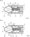
- the control member 121 is mounted in rotation about an axis z121 on the frame 100, preferably on the upper part 102 of the frame 100.
- this axis z121 is included in a plane parallel to the plane ZX while being inclined at an angle ⁇ with respect to the axis Z.
- ⁇ is different from a.
- the z121 axis is inclined by an angle ⁇ 'of between 45 ° and 75 ° relative to the main plane XY. This construction significantly improves the ergonomics of handling of the control member.
- the control member 121 forms a pivot connection or a ball-and-socket connection with the device 123 for transforming movement. This connection allows relative rotation of these two parts around an axis Y transverse to the longitudinal direction X of the frame 100.
- the movement transformation device 123 has a first end 1231 which cooperates with the control member 121 to form this binding.
- the control member 121 and the end 1231 have complementary reliefs so that the rotation of the control member 121 about the axis z121 drives the device 123 in rotation around its axis of rotation z123.
- This axis z123 is inclined by an angle ⁇ with respect to the axis Z.
- ⁇ , ⁇ and ⁇ are different.
- the movement transformation device 123 acts as a cardan joint to transmit the rotation of the control member 121 to the cooperation portion 122.
- control member 121 has a housing 1211 defining a recessed wall 1212.
- the end 1231 of the movement transmission device 123 has a complementary portion of the wall 1212, to fit into the latter, while preventing relative rotation of the control member 121 and of the end 1231 around the axes. z121 and z123.
- This end 1231 is fixed to a drive part 1234 configured to drive the cooperation portion 122.
- the end 1231 comprises drive reliefs 12311 shaped to rotate complementary drive reliefs formed in a housing of the part. drive 1234.
- the drive reliefs 12311 are lugs shaped to fit into housings 12341 formed by the drive part 1234.
- a screw 1233 one head of which is supported on a lower face of the drive part 1234 passes through the latter and cooperates with a nut 1232 inserted in a housing of the first end 1231.
- the first end 1231 is thus made entirely integral with the drive part 1234.
- the latter has a spherical outer wall 12343 complementary to a hollow spherical wall forming a housing 1228 in the lower face 1226 of the cooperation portion 122.
- This housing 1228 of the cooperation portion 122 and the drive part 1234 have complementary reliefs 1229, 12342 making it possible to couple these two parts in rotation around the axes z122 and z123, while allowing rotation around the transverse axis Y to the longitudinal direction X of the frame 100.
- the kinematic connection between the portion of cooperation 122 and the drive part 1234 forms a finger ball joint.
- This structure of the control member 121, of the cooperation portion 122 and of the movement transmission device 123 makes it possible to make the adjustment mechanism 120 particularly compact by being integrated as closely as possible to the shoe while allowing the user to easily and precisely manipulate the control member 121.
- This compactness allows the center of gravity of the binding to be moved backwards, which contributes to better ski balance.
- the motion transmission device 123 is constructed so that the axes z121, z122 and z123 are aligned.
- the actuator 114 of the retaining mechanism 110 forms a lever articulated in rotation on the frame 100 and manipulated by the user to selectively pass the retaining mechanism 110 from the retention configuration to the configuration of release.
- This lever defines a contour, preferably a closed contour.
- This outline is for example defined by branches 1141 extending mainly longitudinally and which meet by a cross member 1142. The interior of the outline defines an opening 1143.
- the control member 121 is dimensioned and arranged so as to be located substantially above the lever when it is in the retention configuration. Thus, in the retention configuration, the control member 121 does not interfere with the lever. The user can then freely manipulate the control member 121 in order to adjust the longitudinal position of the holding mechanism 110, when the boot is engaged with the binding.
- the lever of the actuator 114 and the control member 121 are shaped so that when the latter is in the sliding configuration, it passes through the contour defined by the lever to allow the alternating passage of the lever between the retention and release configurations.
- the control member 121 when the control member 121 is in the transient adjustment configuration, it interferes with the contour and blocks the alternating passage of the lever between the retention and release configurations.
- the control member 121 has a transverse dimension T1, taken in the direction Y, when it is in sliding configuration and it has a transverse dimension T2, taken in the same direction Y, when it is in the transient adjustment configuration.
- T1 is less than T2.
- the transverse dimension, taken in the Y direction, of the opening 1143 is greater than T1 and is less than T2.
- the retaining device 10 can comprise one or two stops to limit the longitudinal movement of the frame 100.
- the device can comprise one or more visual indicators, such as cursors or graduations, making it possible to indicate to the user the position of the binding, more precisely the longitudinal position of the frame 100, with respect to a mark associated with the gliding board 20.
- the graduation can be located on the interface plate 30 or directly on the gliding board 20. This allows the user to more easily adjust the longitudinal position of his boot.
- the adjusting member 1200 is carried by the frame 100.
- the frame 100 can be a single piece unit. Alternatively, the frame 100 can be an assembly of several separate parts or bodies fixed to each other without a degree of freedom.
- the interface plate 30 has all these elements. However, she can only wear one or some of them.
- the interface plate 30 can provide the functions of guiding and retaining the frame 100 without however carrying the rack 32.
- the interface plate 30 can carry the rack without however ensuring the guiding and retaining functions. of the frame 100.
Landscapes
- Engineering & Computer Science (AREA)
- General Engineering & Computer Science (AREA)
- Mechanical Engineering (AREA)
- Footwear And Its Accessory, Manufacturing Method And Apparatuses (AREA)
- Fittings On The Vehicle Exterior For Carrying Loads, And Devices For Holding Or Mounting Articles (AREA)
- Pivots And Pivotal Connections (AREA)
Applications Claiming Priority (1)
| Application Number | Priority Date | Filing Date | Title |
|---|---|---|---|
| FR1902560A FR3093648B1 (fr) | 2019-03-13 | 2019-03-13 | Dispositif de retenue pour planche de glisse |
Publications (2)
| Publication Number | Publication Date |
|---|---|
| EP3708230A1 true EP3708230A1 (de) | 2020-09-16 |
| EP3708230B1 EP3708230B1 (de) | 2023-10-11 |
Family
ID=67262639
Family Applications (1)
| Application Number | Title | Priority Date | Filing Date |
|---|---|---|---|
| EP20162182.8A Active EP3708230B1 (de) | 2019-03-13 | 2020-03-10 | Haltevorrichtung für gleitbrette |
Country Status (2)
| Country | Link |
|---|---|
| EP (1) | EP3708230B1 (de) |
| FR (1) | FR3093648B1 (de) |
Families Citing this family (1)
| Publication number | Priority date | Publication date | Assignee | Title |
|---|---|---|---|---|
| NO349347B1 (no) * | 2024-10-02 | 2025-12-15 | Rottefella As | Langrennsbinding med integrert skinne |
Citations (9)
| Publication number | Priority date | Publication date | Assignee | Title |
|---|---|---|---|---|
| US1422000A (en) * | 1918-03-01 | 1922-07-04 | Henry J Schmick | Cam gearing |
| WO1990005251A1 (en) * | 1987-06-18 | 1990-05-17 | John Douglas Gerisch | Seat adjustment mechanism |
| FR2638974A1 (fr) | 1988-08-16 | 1990-05-18 | Salomon Sa | Fixation de ski de fond de type charniere |
| EP0913102A1 (de) | 1997-10-29 | 1999-05-06 | Salomon S.A. | Sohle fuer sportschuh |
| EP0913103A1 (de) | 1997-10-29 | 1999-05-06 | Salomon S.A. | Sohle fuer sportschuh |
| FR2899121A1 (fr) | 2006-03-29 | 2007-10-05 | Salomon Sa | Ensemble ski de fond et dispositif de fixation de ski de fond |
| WO2012045723A1 (en) | 2010-10-04 | 2012-04-12 | Madshus As | Ski binding |
| WO2017095232A1 (en) | 2015-11-30 | 2017-06-08 | Rottefella As | System for optional dynamic positioning of a ski binding on a ski |
| WO2018143815A1 (en) * | 2017-02-03 | 2018-08-09 | Rottefella As | Mounting plate and mounting plate system for a ski binding |
-
2019
- 2019-03-13 FR FR1902560A patent/FR3093648B1/fr not_active Expired - Fee Related
-
2020
- 2020-03-10 EP EP20162182.8A patent/EP3708230B1/de active Active
Patent Citations (9)
| Publication number | Priority date | Publication date | Assignee | Title |
|---|---|---|---|---|
| US1422000A (en) * | 1918-03-01 | 1922-07-04 | Henry J Schmick | Cam gearing |
| WO1990005251A1 (en) * | 1987-06-18 | 1990-05-17 | John Douglas Gerisch | Seat adjustment mechanism |
| FR2638974A1 (fr) | 1988-08-16 | 1990-05-18 | Salomon Sa | Fixation de ski de fond de type charniere |
| EP0913102A1 (de) | 1997-10-29 | 1999-05-06 | Salomon S.A. | Sohle fuer sportschuh |
| EP0913103A1 (de) | 1997-10-29 | 1999-05-06 | Salomon S.A. | Sohle fuer sportschuh |
| FR2899121A1 (fr) | 2006-03-29 | 2007-10-05 | Salomon Sa | Ensemble ski de fond et dispositif de fixation de ski de fond |
| WO2012045723A1 (en) | 2010-10-04 | 2012-04-12 | Madshus As | Ski binding |
| WO2017095232A1 (en) | 2015-11-30 | 2017-06-08 | Rottefella As | System for optional dynamic positioning of a ski binding on a ski |
| WO2018143815A1 (en) * | 2017-02-03 | 2018-08-09 | Rottefella As | Mounting plate and mounting plate system for a ski binding |
Also Published As
| Publication number | Publication date |
|---|---|
| FR3093648B1 (fr) | 2021-10-29 |
| FR3093648A1 (fr) | 2020-09-18 |
| EP3708230B1 (de) | 2023-10-11 |
Similar Documents
| Publication | Publication Date | Title |
|---|---|---|
| EP1512440B1 (de) | Schuh- oder Fusshaltevorrichtung an einem Sportgerät | |
| EP3260178B2 (de) | Fersenhalter zur befestigung eines schuhes auf einem snowboard | |
| EP1559454B1 (de) | Schuh- oder Fusshaltevorrichtung an einem Sportgerät | |
| EP2446940B1 (de) | Sicherheitsbindung für das Skilaufen | |
| WO1996032992A1 (fr) | Fixation de securite pour le ski de telemark, la randonnee nordique et le saut a ski | |
| EP0825892B1 (de) | Schuhbindungsvorrichtung für einen gleitschuh | |
| EP1935461B1 (de) | Mit einem mindestens zwischen zwei Positionen hin und her schaltbaren, beweglichen Knopf ausgestatteter Artikel | |
| EP4292681B1 (de) | Vorrichtung zum halten eines schuhs auf einem gleitbrett und gleitbrett mit einer solchen vorrichtung | |
| EP3708230B1 (de) | Haltevorrichtung für gleitbrette | |
| EP2903702B1 (de) | Bindungssystem für ein touring-snowboard | |
| EP2552559A1 (de) | Bindung zum üben von skilaufen | |
| EP3785772B1 (de) | Haltevorrichtungen für gleitbrett | |
| FR2745192A1 (fr) | Dispositif de retenue d'une chaussure sur une planche de glisse. | |
| FR2831455A1 (fr) | Ensemble de retenue d'une chaussure sur une planche de glisse | |
| WO1995025567A1 (fr) | Butee avant pour fixation de securite de ski alpin | |
| EP3184156A1 (de) | Skibindung | |
| EP1721641B1 (de) | Bindungsvorrichtung mit einstellbarer Rückhubenergie | |
| EP2889064B1 (de) | Gleitvorrichtung | |
| FR2952308A1 (fr) | Butee avant pour fixation de securite destinee a etre fixee a un ski | |
| FR3141075A1 (fr) | Dispositif de freinage pour une planche de glisse | |
| FR3133020A1 (fr) | Dispositif de fixation arrière pour une planche de glisse | |
| WO2015091912A1 (fr) | Dispositif de liaison d'une chaussure de ski | |
| FR2890871A1 (fr) | Dispositif de retenue d'une chaussure sur une planche de glisse, preferentiellement sur neige. | |
| FR2952548A1 (fr) | Fixation de securite pour la pratique du ski de randonnee |
Legal Events
| Date | Code | Title | Description |
|---|---|---|---|
| PUAI | Public reference made under article 153(3) epc to a published international application that has entered the european phase |
Free format text: ORIGINAL CODE: 0009012 |
|
| STAA | Information on the status of an ep patent application or granted ep patent |
Free format text: STATUS: THE APPLICATION HAS BEEN PUBLISHED |
|
| AK | Designated contracting states |
Kind code of ref document: A1 Designated state(s): AL AT BE BG CH CY CZ DE DK EE ES FI FR GB GR HR HU IE IS IT LI LT LU LV MC MK MT NL NO PL PT RO RS SE SI SK SM TR |
|
| AX | Request for extension of the european patent |
Extension state: BA ME |
|
| STAA | Information on the status of an ep patent application or granted ep patent |
Free format text: STATUS: REQUEST FOR EXAMINATION WAS MADE |
|
| 17P | Request for examination filed |
Effective date: 20210311 |
|
| STAA | Information on the status of an ep patent application or granted ep patent |
Free format text: STATUS: EXAMINATION IS IN PROGRESS |
|
| 17Q | First examination report despatched |
Effective date: 20221011 |
|
| RIC1 | Information provided on ipc code assigned before grant |
Ipc: A63C 9/00 20060101ALN20230126BHEP Ipc: F16H 25/20 20060101ALI20230126BHEP Ipc: F16H 19/00 20060101ALI20230126BHEP Ipc: A63C 5/12 20060101ALI20230126BHEP Ipc: A63C 9/20 20060101ALI20230126BHEP Ipc: A63C 9/08 20060101ALI20230126BHEP Ipc: A63C 9/086 20060101AFI20230126BHEP |
|
| RIC1 | Information provided on ipc code assigned before grant |
Ipc: A63C 9/00 20060101ALN20230213BHEP Ipc: F16H 25/20 20060101ALI20230213BHEP Ipc: F16H 19/00 20060101ALI20230213BHEP Ipc: A63C 5/12 20060101ALI20230213BHEP Ipc: A63C 9/20 20060101ALI20230213BHEP Ipc: A63C 9/08 20060101ALI20230213BHEP Ipc: A63C 9/086 20060101AFI20230213BHEP |
|
| GRAP | Despatch of communication of intention to grant a patent |
Free format text: ORIGINAL CODE: EPIDOSNIGR1 |
|
| STAA | Information on the status of an ep patent application or granted ep patent |
Free format text: STATUS: GRANT OF PATENT IS INTENDED |
|
| RIC1 | Information provided on ipc code assigned before grant |
Ipc: A63C 9/00 20120101ALN20230420BHEP Ipc: F16H 25/20 20060101ALI20230420BHEP Ipc: F16H 19/00 20060101ALI20230420BHEP Ipc: A63C 5/12 20060101ALI20230420BHEP Ipc: A63C 9/20 20120101ALI20230420BHEP Ipc: A63C 9/08 20120101ALI20230420BHEP Ipc: A63C 9/086 20120101AFI20230420BHEP |
|
| INTG | Intention to grant announced |
Effective date: 20230509 |
|
| RIN1 | Information on inventor provided before grant (corrected) |
Inventor name: VERTU, LANDRY Inventor name: YELOVINA, EDDY |
|
| GRAS | Grant fee paid |
Free format text: ORIGINAL CODE: EPIDOSNIGR3 |
|
| GRAA | (expected) grant |
Free format text: ORIGINAL CODE: 0009210 |
|
| STAA | Information on the status of an ep patent application or granted ep patent |
Free format text: STATUS: THE PATENT HAS BEEN GRANTED |
|
| AK | Designated contracting states |
Kind code of ref document: B1 Designated state(s): AL AT BE BG CH CY CZ DE DK EE ES FI FR GB GR HR HU IE IS IT LI LT LU LV MC MK MT NL NO PL PT RO RS SE SI SK SM TR |
|
| REG | Reference to a national code |
Ref country code: GB Ref legal event code: FG4D Free format text: NOT ENGLISH |
|
| REG | Reference to a national code |
Ref country code: CH Ref legal event code: EP |
|
| REG | Reference to a national code |
Ref country code: DE Ref legal event code: R096 Ref document number: 602020018885 Country of ref document: DE |
|
| REG | Reference to a national code |
Ref country code: IE Ref legal event code: FG4D Free format text: LANGUAGE OF EP DOCUMENT: FRENCH |
|
| REG | Reference to a national code |
Ref country code: LT Ref legal event code: MG9D |
|
| REG | Reference to a national code |
Ref country code: NL Ref legal event code: MP Effective date: 20231011 |
|
| REG | Reference to a national code |
Ref country code: AT Ref legal event code: MK05 Ref document number: 1619639 Country of ref document: AT Kind code of ref document: T Effective date: 20231011 |
|
| PG25 | Lapsed in a contracting state [announced via postgrant information from national office to epo] |
Ref country code: NL Free format text: LAPSE BECAUSE OF FAILURE TO SUBMIT A TRANSLATION OF THE DESCRIPTION OR TO PAY THE FEE WITHIN THE PRESCRIBED TIME-LIMIT Effective date: 20231011 |
|
| PG25 | Lapsed in a contracting state [announced via postgrant information from national office to epo] |
Ref country code: GR Free format text: LAPSE BECAUSE OF FAILURE TO SUBMIT A TRANSLATION OF THE DESCRIPTION OR TO PAY THE FEE WITHIN THE PRESCRIBED TIME-LIMIT Effective date: 20240112 |
|
| PG25 | Lapsed in a contracting state [announced via postgrant information from national office to epo] |
Ref country code: IS Free format text: LAPSE BECAUSE OF FAILURE TO SUBMIT A TRANSLATION OF THE DESCRIPTION OR TO PAY THE FEE WITHIN THE PRESCRIBED TIME-LIMIT Effective date: 20240211 |
|
| PG25 | Lapsed in a contracting state [announced via postgrant information from national office to epo] |
Ref country code: LT Free format text: LAPSE BECAUSE OF FAILURE TO SUBMIT A TRANSLATION OF THE DESCRIPTION OR TO PAY THE FEE WITHIN THE PRESCRIBED TIME-LIMIT Effective date: 20231011 |
|
| PG25 | Lapsed in a contracting state [announced via postgrant information from national office to epo] |
Ref country code: AT Free format text: LAPSE BECAUSE OF FAILURE TO SUBMIT A TRANSLATION OF THE DESCRIPTION OR TO PAY THE FEE WITHIN THE PRESCRIBED TIME-LIMIT Effective date: 20231011 |
|
| PG25 | Lapsed in a contracting state [announced via postgrant information from national office to epo] |
Ref country code: ES Free format text: LAPSE BECAUSE OF FAILURE TO SUBMIT A TRANSLATION OF THE DESCRIPTION OR TO PAY THE FEE WITHIN THE PRESCRIBED TIME-LIMIT Effective date: 20231011 |
|
| PG25 | Lapsed in a contracting state [announced via postgrant information from national office to epo] |
Ref country code: LT Free format text: LAPSE BECAUSE OF FAILURE TO SUBMIT A TRANSLATION OF THE DESCRIPTION OR TO PAY THE FEE WITHIN THE PRESCRIBED TIME-LIMIT Effective date: 20231011 Ref country code: IS Free format text: LAPSE BECAUSE OF FAILURE TO SUBMIT A TRANSLATION OF THE DESCRIPTION OR TO PAY THE FEE WITHIN THE PRESCRIBED TIME-LIMIT Effective date: 20240211 Ref country code: GR Free format text: LAPSE BECAUSE OF FAILURE TO SUBMIT A TRANSLATION OF THE DESCRIPTION OR TO PAY THE FEE WITHIN THE PRESCRIBED TIME-LIMIT Effective date: 20240112 Ref country code: ES Free format text: LAPSE BECAUSE OF FAILURE TO SUBMIT A TRANSLATION OF THE DESCRIPTION OR TO PAY THE FEE WITHIN THE PRESCRIBED TIME-LIMIT Effective date: 20231011 Ref country code: BG Free format text: LAPSE BECAUSE OF FAILURE TO SUBMIT A TRANSLATION OF THE DESCRIPTION OR TO PAY THE FEE WITHIN THE PRESCRIBED TIME-LIMIT Effective date: 20240111 Ref country code: AT Free format text: LAPSE BECAUSE OF FAILURE TO SUBMIT A TRANSLATION OF THE DESCRIPTION OR TO PAY THE FEE WITHIN THE PRESCRIBED TIME-LIMIT Effective date: 20231011 Ref country code: PT Free format text: LAPSE BECAUSE OF FAILURE TO SUBMIT A TRANSLATION OF THE DESCRIPTION OR TO PAY THE FEE WITHIN THE PRESCRIBED TIME-LIMIT Effective date: 20240212 |
|
| PG25 | Lapsed in a contracting state [announced via postgrant information from national office to epo] |
Ref country code: SE Free format text: LAPSE BECAUSE OF FAILURE TO SUBMIT A TRANSLATION OF THE DESCRIPTION OR TO PAY THE FEE WITHIN THE PRESCRIBED TIME-LIMIT Effective date: 20231011 Ref country code: RS Free format text: LAPSE BECAUSE OF FAILURE TO SUBMIT A TRANSLATION OF THE DESCRIPTION OR TO PAY THE FEE WITHIN THE PRESCRIBED TIME-LIMIT Effective date: 20231011 Ref country code: PL Free format text: LAPSE BECAUSE OF FAILURE TO SUBMIT A TRANSLATION OF THE DESCRIPTION OR TO PAY THE FEE WITHIN THE PRESCRIBED TIME-LIMIT Effective date: 20231011 Ref country code: NO Free format text: LAPSE BECAUSE OF FAILURE TO SUBMIT A TRANSLATION OF THE DESCRIPTION OR TO PAY THE FEE WITHIN THE PRESCRIBED TIME-LIMIT Effective date: 20240111 Ref country code: LV Free format text: LAPSE BECAUSE OF FAILURE TO SUBMIT A TRANSLATION OF THE DESCRIPTION OR TO PAY THE FEE WITHIN THE PRESCRIBED TIME-LIMIT Effective date: 20231011 Ref country code: HR Free format text: LAPSE BECAUSE OF FAILURE TO SUBMIT A TRANSLATION OF THE DESCRIPTION OR TO PAY THE FEE WITHIN THE PRESCRIBED TIME-LIMIT Effective date: 20231011 |
|
| PG25 | Lapsed in a contracting state [announced via postgrant information from national office to epo] |
Ref country code: DK Free format text: LAPSE BECAUSE OF FAILURE TO SUBMIT A TRANSLATION OF THE DESCRIPTION OR TO PAY THE FEE WITHIN THE PRESCRIBED TIME-LIMIT Effective date: 20231011 |
|
| REG | Reference to a national code |
Ref country code: DE Ref legal event code: R097 Ref document number: 602020018885 Country of ref document: DE |
|
| PG25 | Lapsed in a contracting state [announced via postgrant information from national office to epo] |
Ref country code: CZ Free format text: LAPSE BECAUSE OF FAILURE TO SUBMIT A TRANSLATION OF THE DESCRIPTION OR TO PAY THE FEE WITHIN THE PRESCRIBED TIME-LIMIT Effective date: 20231011 |
|
| PG25 | Lapsed in a contracting state [announced via postgrant information from national office to epo] |
Ref country code: SK Free format text: LAPSE BECAUSE OF FAILURE TO SUBMIT A TRANSLATION OF THE DESCRIPTION OR TO PAY THE FEE WITHIN THE PRESCRIBED TIME-LIMIT Effective date: 20231011 |
|
| PG25 | Lapsed in a contracting state [announced via postgrant information from national office to epo] |
Ref country code: SM Free format text: LAPSE BECAUSE OF FAILURE TO SUBMIT A TRANSLATION OF THE DESCRIPTION OR TO PAY THE FEE WITHIN THE PRESCRIBED TIME-LIMIT Effective date: 20231011 Ref country code: SK Free format text: LAPSE BECAUSE OF FAILURE TO SUBMIT A TRANSLATION OF THE DESCRIPTION OR TO PAY THE FEE WITHIN THE PRESCRIBED TIME-LIMIT Effective date: 20231011 Ref country code: RO Free format text: LAPSE BECAUSE OF FAILURE TO SUBMIT A TRANSLATION OF THE DESCRIPTION OR TO PAY THE FEE WITHIN THE PRESCRIBED TIME-LIMIT Effective date: 20231011 Ref country code: NO Free format text: LAPSE BECAUSE OF FAILURE TO SUBMIT A TRANSLATION OF THE DESCRIPTION OR TO PAY THE FEE WITHIN THE PRESCRIBED TIME-LIMIT Effective date: 20240111 Ref country code: IT Free format text: LAPSE BECAUSE OF FAILURE TO SUBMIT A TRANSLATION OF THE DESCRIPTION OR TO PAY THE FEE WITHIN THE PRESCRIBED TIME-LIMIT Effective date: 20231011 Ref country code: EE Free format text: LAPSE BECAUSE OF FAILURE TO SUBMIT A TRANSLATION OF THE DESCRIPTION OR TO PAY THE FEE WITHIN THE PRESCRIBED TIME-LIMIT Effective date: 20231011 Ref country code: DK Free format text: LAPSE BECAUSE OF FAILURE TO SUBMIT A TRANSLATION OF THE DESCRIPTION OR TO PAY THE FEE WITHIN THE PRESCRIBED TIME-LIMIT Effective date: 20231011 Ref country code: CZ Free format text: LAPSE BECAUSE OF FAILURE TO SUBMIT A TRANSLATION OF THE DESCRIPTION OR TO PAY THE FEE WITHIN THE PRESCRIBED TIME-LIMIT Effective date: 20231011 |
|
| PGRI | Patent reinstated in contracting state [announced from national office to epo] |
Ref country code: NO Effective date: 20240507 |
|
| PLBE | No opposition filed within time limit |
Free format text: ORIGINAL CODE: 0009261 |
|
| STAA | Information on the status of an ep patent application or granted ep patent |
Free format text: STATUS: NO OPPOSITION FILED WITHIN TIME LIMIT |
|
| 26N | No opposition filed |
Effective date: 20240712 |
|
| PG25 | Lapsed in a contracting state [announced via postgrant information from national office to epo] |
Ref country code: SI Free format text: LAPSE BECAUSE OF FAILURE TO SUBMIT A TRANSLATION OF THE DESCRIPTION OR TO PAY THE FEE WITHIN THE PRESCRIBED TIME-LIMIT Effective date: 20231011 |
|
| PG25 | Lapsed in a contracting state [announced via postgrant information from national office to epo] |
Ref country code: SI Free format text: LAPSE BECAUSE OF FAILURE TO SUBMIT A TRANSLATION OF THE DESCRIPTION OR TO PAY THE FEE WITHIN THE PRESCRIBED TIME-LIMIT Effective date: 20231011 |
|
| REG | Reference to a national code |
Ref country code: CH Ref legal event code: PL |
|
| PG25 | Lapsed in a contracting state [announced via postgrant information from national office to epo] |
Ref country code: LU Free format text: LAPSE BECAUSE OF NON-PAYMENT OF DUE FEES Effective date: 20240310 |
|
| PG25 | Lapsed in a contracting state [announced via postgrant information from national office to epo] |
Ref country code: MC Free format text: LAPSE BECAUSE OF FAILURE TO SUBMIT A TRANSLATION OF THE DESCRIPTION OR TO PAY THE FEE WITHIN THE PRESCRIBED TIME-LIMIT Effective date: 20231011 |
|
| GBPC | Gb: european patent ceased through non-payment of renewal fee |
Effective date: 20240310 |
|
| PG25 | Lapsed in a contracting state [announced via postgrant information from national office to epo] |
Ref country code: MC Free format text: LAPSE BECAUSE OF FAILURE TO SUBMIT A TRANSLATION OF THE DESCRIPTION OR TO PAY THE FEE WITHIN THE PRESCRIBED TIME-LIMIT Effective date: 20231011 Ref country code: LU Free format text: LAPSE BECAUSE OF NON-PAYMENT OF DUE FEES Effective date: 20240310 |
|
| REG | Reference to a national code |
Ref country code: BE Ref legal event code: MM Effective date: 20240331 |
|
| PG25 | Lapsed in a contracting state [announced via postgrant information from national office to epo] |
Ref country code: BE Free format text: LAPSE BECAUSE OF NON-PAYMENT OF DUE FEES Effective date: 20240331 |
|
| PG25 | Lapsed in a contracting state [announced via postgrant information from national office to epo] |
Ref country code: GB Free format text: LAPSE BECAUSE OF NON-PAYMENT OF DUE FEES Effective date: 20240310 |
|
| PG25 | Lapsed in a contracting state [announced via postgrant information from national office to epo] |
Ref country code: IE Free format text: LAPSE BECAUSE OF NON-PAYMENT OF DUE FEES Effective date: 20240310 |
|
| PG25 | Lapsed in a contracting state [announced via postgrant information from national office to epo] |
Ref country code: IE Free format text: LAPSE BECAUSE OF NON-PAYMENT OF DUE FEES Effective date: 20240310 Ref country code: GB Free format text: LAPSE BECAUSE OF NON-PAYMENT OF DUE FEES Effective date: 20240310 Ref country code: BE Free format text: LAPSE BECAUSE OF NON-PAYMENT OF DUE FEES Effective date: 20240331 Ref country code: CH Free format text: LAPSE BECAUSE OF NON-PAYMENT OF DUE FEES Effective date: 20240331 |
|
| PG25 | Lapsed in a contracting state [announced via postgrant information from national office to epo] |
Ref country code: CY Free format text: LAPSE BECAUSE OF FAILURE TO SUBMIT A TRANSLATION OF THE DESCRIPTION OR TO PAY THE FEE WITHIN THE PRESCRIBED TIME-LIMIT; INVALID AB INITIO Effective date: 20200310 |
|
| PG25 | Lapsed in a contracting state [announced via postgrant information from national office to epo] |
Ref country code: HU Free format text: LAPSE BECAUSE OF FAILURE TO SUBMIT A TRANSLATION OF THE DESCRIPTION OR TO PAY THE FEE WITHIN THE PRESCRIBED TIME-LIMIT; INVALID AB INITIO Effective date: 20200310 |
|
| PG25 | Lapsed in a contracting state [announced via postgrant information from national office to epo] |
Ref country code: FI Free format text: LAPSE BECAUSE OF FAILURE TO SUBMIT A TRANSLATION OF THE DESCRIPTION OR TO PAY THE FEE WITHIN THE PRESCRIBED TIME-LIMIT Effective date: 20231011 |
|
| PG25 | Lapsed in a contracting state [announced via postgrant information from national office to epo] |
Ref country code: TR Free format text: LAPSE BECAUSE OF FAILURE TO SUBMIT A TRANSLATION OF THE DESCRIPTION OR TO PAY THE FEE WITHIN THE PRESCRIBED TIME-LIMIT Effective date: 20231011 |
|
| PGFP | Annual fee paid to national office [announced via postgrant information from national office to epo] |
Ref country code: NO Payment date: 20260223 Year of fee payment: 7 Ref country code: DE Payment date: 20260219 Year of fee payment: 7 |
|
| PGFP | Annual fee paid to national office [announced via postgrant information from national office to epo] |
Ref country code: FR Payment date: 20260219 Year of fee payment: 7 |