EP3708230A1 - Retaining device for a glideboard - Google Patents
Retaining device for a glideboard Download PDFInfo
- Publication number
- EP3708230A1 EP3708230A1 EP20162182.8A EP20162182A EP3708230A1 EP 3708230 A1 EP3708230 A1 EP 3708230A1 EP 20162182 A EP20162182 A EP 20162182A EP 3708230 A1 EP3708230 A1 EP 3708230A1
- Authority
- EP
- European Patent Office
- Prior art keywords
- frame
- relief
- rack
- reliefs
- complementary
- Prior art date
- Legal status (The legal status is an assumption and is not a legal conclusion. Google has not performed a legal analysis and makes no representation as to the accuracy of the status listed.)
- Granted
Links
- 230000007246 mechanism Effects 0.000 claims abstract description 50
- 230000000295 complement effect Effects 0.000 claims description 102
- 230000001052 transient effect Effects 0.000 claims description 13
- 230000000694 effects Effects 0.000 claims description 4
- 230000033001 locomotion Effects 0.000 description 22
- 230000014759 maintenance of location Effects 0.000 description 12
- 230000008901 benefit Effects 0.000 description 11
- 230000005540 biological transmission Effects 0.000 description 11
- 238000010276 construction Methods 0.000 description 8
- 230000005484 gravity Effects 0.000 description 5
- 239000000463 material Substances 0.000 description 5
- 230000009466 transformation Effects 0.000 description 5
- 238000009825 accumulation Methods 0.000 description 3
- 230000000903 blocking effect Effects 0.000 description 3
- PEDCQBHIVMGVHV-UHFFFAOYSA-N Glycerine Chemical compound OCC(O)CO PEDCQBHIVMGVHV-UHFFFAOYSA-N 0.000 description 2
- 238000010521 absorption reaction Methods 0.000 description 2
- 230000037147 athletic performance Effects 0.000 description 2
- 230000006378 damage Effects 0.000 description 2
- 238000006073 displacement reaction Methods 0.000 description 2
- 238000000926 separation method Methods 0.000 description 2
- 238000004904 shortening Methods 0.000 description 2
- 208000012661 Dyskinesia Diseases 0.000 description 1
- 241001272720 Medialuna californiensis Species 0.000 description 1
- 241000287107 Passer Species 0.000 description 1
- 208000027418 Wounds and injury Diseases 0.000 description 1
- 230000004913 activation Effects 0.000 description 1
- 238000000576 coating method Methods 0.000 description 1
- 230000001010 compromised effect Effects 0.000 description 1
- 230000007423 decrease Effects 0.000 description 1
- 229940082150 encore Drugs 0.000 description 1
- 230000007717 exclusion Effects 0.000 description 1
- 208000014674 injury Diseases 0.000 description 1
- 230000010354 integration Effects 0.000 description 1
- 239000002184 metal Substances 0.000 description 1
- 230000017311 musculoskeletal movement, spinal reflex action Effects 0.000 description 1
- 230000000717 retained effect Effects 0.000 description 1
- 230000035939 shock Effects 0.000 description 1
- 230000037078 sports performance Effects 0.000 description 1
- 239000000758 substrate Substances 0.000 description 1
- 210000003371 toe Anatomy 0.000 description 1
- 230000001131 transforming effect Effects 0.000 description 1
- 230000000007 visual effect Effects 0.000 description 1
- 239000013585 weight reducing agent Substances 0.000 description 1
Images


Classifications
-
- A—HUMAN NECESSITIES
- A63—SPORTS; GAMES; AMUSEMENTS
- A63C—SKATES; SKIS; ROLLER SKATES; DESIGN OR LAYOUT OF COURTS, RINKS OR THE LIKE
- A63C9/00—Ski bindings
- A63C9/08—Ski bindings yieldable or self-releasing in the event of an accident, i.e. safety bindings
- A63C9/086—Ski bindings yieldable or self-releasing in the event of an accident, i.e. safety bindings using parts which are fixed on the shoe of the user and are releasable from the ski binding
-
- A—HUMAN NECESSITIES
- A63—SPORTS; GAMES; AMUSEMENTS
- A63C—SKATES; SKIS; ROLLER SKATES; DESIGN OR LAYOUT OF COURTS, RINKS OR THE LIKE
- A63C5/00—Skis or snowboards
- A63C5/12—Making thereof; Selection of particular materials
- A63C5/128—A part for the binding being integrated within the board structure, e.g. plate, rail, insert
-
- A—HUMAN NECESSITIES
- A63—SPORTS; GAMES; AMUSEMENTS
- A63C—SKATES; SKIS; ROLLER SKATES; DESIGN OR LAYOUT OF COURTS, RINKS OR THE LIKE
- A63C9/00—Ski bindings
- A63C9/003—Non-swivel sole plate fixed on the ski
-
- A—HUMAN NECESSITIES
- A63—SPORTS; GAMES; AMUSEMENTS
- A63C—SKATES; SKIS; ROLLER SKATES; DESIGN OR LAYOUT OF COURTS, RINKS OR THE LIKE
- A63C9/00—Ski bindings
- A63C9/005—Ski bindings with means for adjusting the position of a shoe holder or of the complete binding relative to the ski
-
- A—HUMAN NECESSITIES
- A63—SPORTS; GAMES; AMUSEMENTS
- A63C—SKATES; SKIS; ROLLER SKATES; DESIGN OR LAYOUT OF COURTS, RINKS OR THE LIKE
- A63C9/00—Ski bindings
- A63C9/08—Ski bindings yieldable or self-releasing in the event of an accident, i.e. safety bindings
- A63C9/0807—Ski bindings yieldable or self-releasing in the event of an accident, i.e. safety bindings for both towing and downhill skiing
-
- A—HUMAN NECESSITIES
- A63—SPORTS; GAMES; AMUSEMENTS
- A63C—SKATES; SKIS; ROLLER SKATES; DESIGN OR LAYOUT OF COURTS, RINKS OR THE LIKE
- A63C9/00—Ski bindings
- A63C9/20—Non-self-releasing bindings with special sole edge holders instead of toe-straps
-
- F—MECHANICAL ENGINEERING; LIGHTING; HEATING; WEAPONS; BLASTING
- F16—ENGINEERING ELEMENTS AND UNITS; GENERAL MEASURES FOR PRODUCING AND MAINTAINING EFFECTIVE FUNCTIONING OF MACHINES OR INSTALLATIONS; THERMAL INSULATION IN GENERAL
- F16H—GEARING
- F16H25/00—Gearings comprising primarily only cams, cam-followers and screw-and-nut mechanisms
- F16H25/18—Gearings comprising primarily only cams, cam-followers and screw-and-nut mechanisms for conveying or interconverting oscillating or reciprocating motions
- F16H25/20—Screw mechanisms
- F16H25/2015—Means specially adapted for stopping actuators in the end position; Position sensing means
-
- A—HUMAN NECESSITIES
- A63—SPORTS; GAMES; AMUSEMENTS
- A63C—SKATES; SKIS; ROLLER SKATES; DESIGN OR LAYOUT OF COURTS, RINKS OR THE LIKE
- A63C9/00—Ski bindings
- A63C2009/008—Ski bindings with a binding element sliding along a rail during use or setting
Definitions
- the invention relates to the field of devices for retaining a boot on a gliding board. It relates more particularly to retaining devices which allow longitudinal adjustment of the position of the boot on the gliding board. It finds a particularly advantageous application in cross-country skiing.
- the retaining device comprises a frame carrying a mechanism for hooking an element belonging to the boot, the frame also carrying an adjustment member. When the user actuates the adjustment member, the frame moves longitudinally on the gliding board, while the boot remains in engagement with the retaining device.
- An object of the present invention is therefore to provide a retaining device making it possible to limit, or even eliminate, at least one of the drawbacks mentioned above.
- the adjustment member comprises a cooperation portion mounted in rotation about an axis of rotation inclined at an angle ⁇ of between 30 ° and 90 ° relative to said main plane (XY) in which mainly extends the lower face. of the chassis, the cooperation portion comprising a lower face bearing at least a first relief.
- the at least one first relief has at least two lateral flanks extending respectively along a curved trajectory shaped so that the distance between a point of one of these trajectories and said axis of rotation varies progressively throughout minus part of the curved path.
- the first relief is configured so that its lateral flanks are able to cooperate with contact surfaces of complementary reliefs of the rack so as to cause the longitudinal sliding of the frame relative to the gliding board under the effect of the rotation of the rack. the cooperation portion around said axis.
- control member is easily accessible. This allows the user to adjust the longitudinal position of his shoe easily and quickly, thereby leading to improved sports performance and comfort.
- this construction allows a particularly compact integration of the adjustment member in the binding. This allows in particular a good balance of the gliding board.
- the weight of the adjustment mechanism can be located near the shoe's holding mechanism.
- the adjustment mechanism is positioned towards the front of the gliding board and at a variable distance from the holding mechanism of the boot, which tends to unbalance the gliding board.
- the adjustment member is little exposed. This leads to reducing the risks of unintentional handling by external elements which can interfere with the restraint device during sliding.
- external elements can for example be another gliding board, typically the user's other ski, roots, safety nets, etc.
- this construction makes it possible to protect the cooperation portion of the adjustment member from the external environment (snow, frost).
- the solution allows adjustment of the longitudinal position of the boot while the latter remains in engagement with the holding mechanism.
- this solution makes it possible to adjust the longitudinal position of the boot over a long stroke length.
- the invention thus offers an improved amplitude of adjustment compared to solutions in which a rack with straight teeth would be driven by a pinion in rotation about a horizontal axis transverse to that of the gliding board.
- the invention provides a retaining device adaptable to a multitude of gliding boards requiring few interfacing elements with the retaining device.
- the retaining device can be mounted directly on the gliding board or on a single intermediate piece, an interface plate, integral with the gliding board.
- a user may prefer one pair of skis over another. Thanks to the invention, he can easily remove the retaining device from a first pair of skis for use on a second pair of skis by handling only very few parts: the retaining device and the gliding board, equipped or not with an interface plate. This is made possible by the fact that the adjusting member making it possible to modify the longitudinal position of the boot is carried, preferably entirely, by the latter's retaining device.
- the rack is formed by an upper face of the gliding board itself.
- the rack is formed by an interface plate which is attached to an upper face of the gliding board. This second embodiment makes it possible to very easily adapt a gliding board so that it becomes compatible with the retaining device according to the invention.
- the invention may further have at least any one of the following characteristics: According to one example, the axis of rotation is included in a median longitudinal plane of the frame.
- the cooperation portion comprises at least one second relief having two lateral flanks respectively extending along a curved path shaped so that the distance between a point of one of the paths of the lateral flanks of the second relief and said axis of rotation gradually varies along at least part of this curved path.
- the two lateral flanks of the second relief are angularly offset with respect to the lateral flanks of the first relief.
- the relief has a curved shape, such as a portion of a spiral, which extends at an angle greater than 180 °.
- the relief has a curved shape, such as a portion of a spiral, which extends at an angle of less than 360 °. This makes it possible to limit the size of the adjustment mechanism. The balance of the gliding board is improved.
- the adjustment member comprises at least one indexing element able to cooperate with a complementary indexing element integral with the frame so as to maintain the cooperation portion in at least one stable angular position.
- the adjustment of the longitudinal position of the shoe is thus made more intuitive, quick and easy. This leads to improving the performance of the skier. Moreover, this makes it possible to reduce, or even avoid, the risks of involuntary manipulation of the adjustment member.
- the at least one stable angular position corresponds to the sliding configuration.
- the cooperation portion is dimensioned and arranged so that when a first portion of the first relief is able to engage with at least one complementary relief of the rack, a second portion of the first relief, arranged in opposition by relative to the axis of rotation, is no longer able to cooperate with at least one complementary relief of the rack.
- the lower face of the cooperation portion is conical.
- the adjustment member comprises a control member configured to be manipulated by the user in order to drive the cooperation portion in rotation around the axis of rotation.
- the frame has an upper part and a lower housing intended to be rotated with respect to the rack, the cooperation portion being housed in said lower housing.
- the retainer includes a control member configured to be manipulated by the user to rotate the cooperating portion about the axis of rotation.
- the control member is positioned above the upper part of the chassis to be accessible manually by the user.
- cooperation portion is housed inside the housing defined by the frame protects the latter from impact and weathering. In particular, this makes it possible to prevent frost or the accumulation of snow from blocking the cooperation of the reliefs such as ribs with the rack.
- the holding mechanism comprises an actuation lever articulated in rotation on the frame, defining a contour, the lever being manipulable by the user between a retention configuration for which the holding mechanism retains the boot and a configuration release for which the holding mechanism authorizes the release of the shoe from the device retainer, the control member being dimensioned and arranged so as to be located above the lever when the latter is in the retention configuration and so as to be able to pass through said contour when passing through the retention configuration to the release configuration.
- the actuating lever has at least two branches extending mainly longitudinally. This embodiment also makes it possible to protect the adjustment mechanism against impacts.
- said main plane in which the lower face of the chassis mainly extends corresponds to a plane parallel to the sliding plane of the gliding board.
- the main plane is substantially horizontal.
- the cooperation portion forms a disc.
- the holding mechanism comprises a jaw movable between an engagement position for which the movable jaw is able to cooperate with the hooking element so as to allow the attachment of the hooking element with the device.
- retainer while allowing rotation of the boot about an axis transverse to the retainer, and a release position for which the movable jaw is in a configuration allowing the separation of the fastening element from the retainer .
- An actuator such as a lever controls a movement of the movable jaw to make it tilt from the engagement position to the release position.
- Another aspect of the present invention relates to an interface plate, extending mainly along a longitudinal axis, and comprising a rack. having complementary reliefs distributed parallel to said longitudinal axis of the interface plate.
- Each complementary relief has at least two curved contact surfaces configured to cooperate with contact surfaces carried by at least one first relief carried by a cooperation portion of a frame of a retaining device for a sliding shoe.
- the at least one first relief has at least two lateral flanks extending respectively along a curved trajectory shaped so that the distance between a point of one of these trajectories and an axis of rotation around which the portion is mounted in rotation. cooperation varies progressively along at least a part of the curved path, so that the rotation of the cooperation portion about its axis of rotation causes the longitudinal sliding of the frame along said longitudinal axis of the interface plate.
- Another aspect of the present invention relates to an interface plate suitable for fixing to a gliding board, and comprising at least one rack configured to cooperate with the adjustment member of a retaining device according to the invention.
- the interface plate extends mainly along a longitudinal axis, the rack having reliefs of which at least one surface is curved.
- these complementary reliefs include at least one curved contact surface.
- the interface plate extends mainly along a longitudinal axis, the rack having reliefs whose alignment is off-center relative to said longitudinal axis of the interface plate. This has the advantage of facilitating longitudinal movement with the adjustment member described above.
- the interface plate comprises complementary reliefs carried by the rack, the complementary reliefs having an asymmetric shape with respect to the longitudinal axis of the interface plate.
- the rack is provided on one of the gliding board and on an interface plate.
- the interface plate can be glued or screwed onto the gliding board.
- the complementary retaining element is formed by one of: the gliding board and an interface plate integral with the gliding board.
- the rack is carried by the complementary retaining element.
- Another aspect of the present invention relates to an assembly comprising a retaining device according to the invention and an interface plate according to the invention.
- Another aspect of the present invention relates to a gliding board equipped with a retaining device according to the invention.
- the gliding board comprises a rack formed by one face of the gliding board.
- the gliding board includes a interface plate, attached to one face of the gliding board and forming at least one of the rack and the complementary retaining element.
- rack designates a mechanical device having complementary reliefs able to cooperate with reliefs of a drive part so that, when the drive part is handled, this cooperation causes the translation of the drive part.
- complementary reliefs or notches are distributed in a substantially linear manner.
- the term “on”, “overcomes” or “underlying” or their equivalents do not necessarily mean “in contact with”.
- first part is placed on a second part, this does not necessarily mean that the two parts are directly in contact with one another, but it means that the first part at least partially covers the second part in being either directly in contact with it or by being separated from it by another part or another element.
- the term “integral” used to qualify the connection between two parts means that the two parts are linked / fixed with respect to each other, according to all the degrees of freedom unless it is explicitly specified differently. For example, if it is indicated that two parts are integral in translation in an X direction, this means that the parts can be mobile, possibly according to several degrees of freedom, to the exclusion of the freedom in translation in the X direction. In other words, if we move a part in the X direction, the other part performs the same movement.
- the main objectives of the invention are the compactness of the binding and its weight reduction, mainly for cross-country skiing or hiking.
- the invention thus makes it possible to take full advantage of the intrinsic performance of the gliding board by having a very good distribution of masses. It is important to avoid a center of gravity positioned too far forward, in particular in front of the axis of rotation of the boot relative to the ski board. In fact, if this is the case, the risk of planting the front tip of the ski board in the snow during propulsion movements is increased.
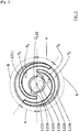
- the figure 1 in particular illustrates a gliding board 20 equipped with a retaining device 10, usually designated by the term “binding”, for a gliding boot (not shown in the figures).
- the gliding board 20 has an upper face 21 facing the retaining device 10 and a lower face 22 intended to come into contact with the substrate, typically snow.
- the lower face 22 thus defines a surface and a sliding plane.
- the sliding plane corresponds to the XY plane of the XYZ orthogonal coordinate system illustrated in figure 1 .
- the retaining device 10 comprises a frame 100 carrying a retaining mechanism 110 for a sliding boot.
- the retention mechanism 110 selectively allows the shoe to be engaged with the retaining device 10 or to release the boot from the retaining device 10.
- the boot can be completely fixed with respect to the retaining device 10. This is for example the case downhill skiing.
- the holding mechanism 110 allows the boot to retain one or more degrees of freedom.
- the boot is articulated in rotation on the retaining device 10 about a horizontal axis transverse to the sliding direction, at the toes.
- the example shown in figure 1 applies, for example, to cross-country skiing.
- the boot then comprises an attachment element, typically a shaft extending in a direction substantially transverse Y to the main longitudinal direction X of the gliding board, when the boot is engaged with the holding mechanism.
- the hooking element is integrated in a recess in the front of the sole of the shoe.
- the shoe can, for example, comply with the technical teaching of the requests EP-A-0 913 102 and or EP-A-0 913 103 which we can refer to for more details.
- the retaining mechanism 110 comprises a fixed jaw 112, a movable jaw 113, an actuator 114 and a movement transformation device 115.
- the actuator 114 such as a lever, controls a movement of the movable jaw 113 to selectively move it from the engagement position to the release position and vice versa.
- the transmission of the movement between the actuator 114 and the movable jaw 113 is ensured by the movement transformation device 115.
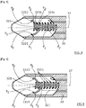
- Elements of this movement transformation device 115 are illustrated in figure 2 . They include, in this example, connecting rods 1151, pins 1152 connecting a first end of connecting rods 1151 with the actuator 114, a pin 1153 connecting a second end of connecting rods 1151 with the frame 100 and pins 1154 connecting the actuator 114 with the movable jaw 113.
- the figure 2 also makes visible the arrangements made on the frame 100, namely, a through hole 1156 for the passage of the pin 1153 and oblong holes 1157 for the passage of the pin 1154.
- the movable jaw includes holes 1132 for the passage of a pin 1154.
- the retaining device 10 also comprises an elastic part 130 against which the front of the sliding boot is intended to come into contact.
- This elastic part 130 is usually referred to as a “flexor”.
- An adjustment mechanism 120 carried in part by the frame 100, enables the frame 100 to be moved longitudinally relative to the gliding board 20.
- the adjustment mechanism 120 comprises a rack 32 integral with the gliding board 20. and an adjustment member 1200 configured to cooperate with the rack 32.
- the adjustment member 1200 comprises a control member 121, a cooperation portion 122 and, optionally, a movement transmission device 123.
- the adjustment member 1200 When the adjustment member 1200 is actuated, it causes the longitudinal sliding of the frame 100 relative to the gliding board 20.
- the boot being retained by the holding mechanism 110 carried by the frame 100, it is also driven in translation and the user can adjust its longitudinal position relative to the gliding board.
- the frame 100 has a median longitudinal axis, parallel to the X direction, and comprises two profiles, located on either side of this median longitudinal axis. Each of these profiles form an emerging longitudinal groove 106, transversely, in the direction of the median longitudinal axis. These two grooves, facing each other, are intended to receive respectively a guide rail 31 carried by a complementary retaining element integral with the gliding board 20. These grooves each form a slide 101. Each of these slides 101 is thus guided in translation by the rail 31.
- the complementarity of the frame 100 and the complementary retaining element in addition to providing a translational guiding function, prevents a distance of the frame 100 from the gliding board 20 in the Z direction.
- the kinematic connection formed by each slide 101 and its complementary rail 31 is a sliding connection, that is to say a connection with a single degree of freedom corresponding to the sliding of the frame 100 according to direction X.
- the rails 31 of the additional retaining element are carried by an interface plate 30 integral with the gliding board 20.
- the interface plate 30 is attached to the gliding board 20.
- a lower face 38 of the interface plate 30 is placed directly in contact with the upper face 21 of the gliding board 20.
- the interface plate 30 is for example glued or screwed onto the gliding board 20.
- the sliding board 20 forms the rails 31 for guiding and retaining.
- the complementary retaining element carrying the rails 31 is formed directly by the gliding board 20.
- the frame 100 may have a lower face 103 provided with additional slides 104.
- These additional slides 104 are shaped to cooperate with complementary grooves 35 integral with the gliding board 20.
- these grooves Complementary 35 are carried by the interface plate 30.
- these complementary grooves 35 can be formed directly by the gliding board 20.
- these complementary grooves 35 extend in a direction parallel to the 'X axis.
- the rack 32 of the adjustment mechanism appears more distinctly on the figures 2 , 3 , 4 , and 5 .
- the rack 32 has several complementary reliefs 321.
- these complementary reliefs 321 each have at least one curved contact surface Y1, Y2 capable of cooperating with at least one lateral flank X1, X2 of a relief 1221, 1222 driven by the adjustment member 1200.
- each complementary relief 321 is delimited by two curved contact surfaces whose edges meet.
- Each complementary relief 321 has the shape of a portion of the moon.
- Other forms of complementary relief are perfectly conceivable.
- the complementary reliefs 321 can form portions of truncated moons, or pads, as will be described with reference to figures 9 and 10 .
- the adjuster 1200 of the adjuster 120 appears more distinctly on the figures 2 , 3 , 6 and 7 .
- the adjustment member 1200 comprises a cooperation portion 122, for example having the shape of a disc and bearing at least one relief 1221, 1222.
- the cooperation portion 122 has a lower face 1226 bearing two reliefs 1221, 1222. This number of reliefs is not limiting. These two reliefs 1221, 1222 appear in figure 6 and 7 .
- the adjustment mechanism 120 is shaped so that the actuation of the adjustment member 1200 causes the rotation of the cooperation portion 122 about an axis of rotation z122.
- the relief (s) 1221, 1222 carried by the cooperation portion 122 have two lateral flanks X1, X2 extending respectively along a curved path shaped so that the distance between a point of one of these paths and said axis of rotation z122 of the cooperation portion 122 gradually varies when one traverses part of the curved path.
- the lateral flanks X1, X2 are shaped to cooperate with the contact surfaces Y1, Y2 of the complementary reliefs 321 carried by the rack 32 so as to cause the longitudinal sliding of the frame 100 relative to the gliding board 20 under the effect of the rotation of the cooperation portion 122 about said axis of rotation z122.
- the relief (s) 1221, 1222 carried by the cooperation portion 122 each form a projection, typically on the lower face 1226 of the cooperation portion 122.
- Each relief 1221, 1222 forms a rib. It is this embodiment which is illustrated in the figures. According to an alternative example, these reliefs are hollow. The following description describes the illustrated embodiment having ribs. Nevertheless, each characteristics and advantages mentioned above are perfectly applicable to the embodiments with hollow reliefs.
- the relief (s) 1221, 1222 carried by the cooperation portion 122 can each form a spiral portion. Consequently, the lateral flanks X1, X2 can also each form a portion of a spiral.
- a spiral or portion of a spiral is a curve which evolves around an axis away from the latter.
- this axis corresponds to the axis of rotation z122 of the cooperation portion 122 and passes through the center 1220 of the spiral.
- the spiral has a constant pitch.
- the figure 7 illustrates an embodiment in which the rib has a constant pitch.
- the axis of rotation z122 of the cooperation portion 122 is inclined at an angle ⁇ relative to the main plane in which the lower face 103 of the frame 100 extends. This plane is substantially parallel to the XY plane and to the sliding plane. of the board slides 20.
- the angle ⁇ is between 30 ° and 90 °.
- the axis of rotation z122 is included in a median longitudinal plane of the frame 100, this median longitudinal plane being parallel to the plane ZX.
- the adjustment member 1200 comprises a control member 121 which can be manipulated by the user in order to drive the cooperation portion 122 in rotation about its axis z122.
- control member 121 is a rotation of the control member 121 which causes the rotation of the cooperation portion 122 about its axis z122.
- the control member 121 can be fixed with respect to the cooperation portion 122, that is to say that it has no degree of freedom with respect to the latter.
- the control member 121 drives the cooperation portion 122 in rotation by means of a device 123 for transmitting movements which will be described in more detail below.
- control member 121 When the control member 121 is driven in rotation, it drives the cooperation portion 122 in rotation around the axis z122.
- the at least one relief 1221, 1222 of the cooperation portion 122 for example each forming a spiral portion, cooperates or engages with the complementary reliefs 321 of the rack 32 which causes the sliding of the frame 100.
- the cooperation portion 122 comprises two reliefs 1221, 1222, here two ribs. Each of these reliefs forms a portion of a spiral centered on the axis of rotation z122. Preferably these two portions of the spiral have the same pitch. These two spiral portions are angularly offset. Thus, for a given angle their radial position is different.
- each of these two reliefs 1221, 1222 of the cooperation portion 122 has two lateral flanks X1, X2 respectively extending along a curved path shaped so that the distance between a point of one of the trajectories of the lateral flanks X1, X2 of a relief 1221, 1222 and said axis of rotation z122 varies progressively along at least part of this curved trajectory.
- the two lateral flanks of the second relief 1222 are angularly offset with respect to the lateral flanks of the first relief 1221.
- This construction makes it possible to have, for certain angular positions of the cooperation portion 122, the two reliefs 1221, 1222 which simultaneously cooperate with several complementary reliefs 321 of the rack 32.
- This configuration is illustrated in figure 3 .
- the portions of spiral 1221 ', 1222' are simultaneously engaged with the complementary reliefs 321 '. This allows better transmission of forces in a longitudinal direction X, between the binding and the gliding board, in particular during the phases of propulsion of the skier.
- each of the two reliefs 1221, 1222 does not necessarily extend over a great length.
- each relief 1221, 1222 in this example each portion of a spiral, extends over an angular sector less than 360 ° and preferably less than 180 °. This makes it possible to considerably limit the radial extension of the cooperation portion 122. If the latter has the shape of a disc, then the presence of at least two spiral portions makes it possible to reduce its diameter.
- an embodiment with several reliefs 1221, 1222, typically several portions of shorter spirals, extending over an angle less than 360 °, is more advantageous than an embodiment which would have only one relief 1221 , 1222, typically only a single spiral, extending over a portion greater than 360 °.
- the cooperation portion 122 would have a necessarily larger diameter.
- the embodiment with several portions of spirals thus makes it possible to make the adjustment mechanism 120 more compact by substantially reducing its bulk. This thus makes it possible to better integrate the binding on the gliding board 20 and in particular to design a relatively narrow frame 100 whose width is less than the width of the gliding board 20.
- the retaining device 10 also referred to as binding, does not extend much or not beyond the lateral edges of the ski. This avoids the risk of contact or injury with the frame 100, hindrance in the movements of the skier or even damage the frame 100. This therefore increases the strength of the binding and therefore its reliability. By being more compact, this also allows the center of gravity of the binding to be moved backwards, which contributes to better ski balance.
- the adjustment member 1200 is configured so that the cooperation portion 122 can be positioned angularly, around said axis z122, according to at least two configurations among which: a sliding configuration for which the at least two reliefs 1221, 1222 are able to be simultaneously engaged with the rack 32 and a transient adjustment configuration for which only one of the reliefs is able to engage with rack 32.
- the sliding configuration corresponds to the configuration for which at least the first and the second reliefs 1221, 1222 are able to be simultaneously engaged with at least one of the complementary reliefs 321 of the rack 32 and the adjustment configuration transient corresponds to the configuration for which only some and preferably only one of the at least two reliefs 1221, 1222 are able to engage with at least one of the complementary reliefs 321 of the rack 32.
- This feature makes it possible to reinforce the robustness in the sliding configuration since two reliefs are engaged in this configuration, while limiting the size of the adjustment mechanism 120, due to the fact that a single relief is in engagement with the rack 32 in this configuration. transient adjustment.
- the size of the adjustment mechanism 120 is further reduced and the balancing of the gliding board 20 is further improved.
- this also makes it possible to optimize the weight of the binding.
- the relief is dimensioned so that, only in the sliding configurations, there is sufficient material, with two reliefs engaged, to transmit the longitudinal forces.
- the number of reliefs in engagement is reduced, with a single relief in engagement. The material is then minimized, which saves the weight of the sliding device.
- each relief 1221, 1222 typically each spiral or portion of a spiral, extends over approximately an angular sector of between 200 ° and 240 °.
- the two reliefs 1221, 1222 are arranged so as to have two overlapping zones A, each corresponding to an angular sector in which a radius starting from the center 1220 meets each of the reliefs 1221, 1222.
- These two overlapping zones A are arranged symmetrically with on either side of the center 1220.
- the other angular sectors correspond to non-overlapping zones B, illustrated in figure 7 .
- the cooperation portion 122 is angularly positioned so as to engage the or one of the overlapping zones A with the rack 32 It follows that the two reliefs 1221, 1222 are then engaged with complementary reliefs 321 of the rack 32.
- the cooperation portion 122 is angularly positioned so as to engage a non-overlapping zone B with the rack 32. It s' It follows that only one of the two reliefs 1221, 1222 is then engaged with complementary reliefs 321 of the rack 32.
- the adjustment mechanism comprises an indexing device configured to maintain the control member 121 in a position of stable equilibrium when the latter is in the sliding configuration.
- an involuntary activation of the control member 121 is avoided when the latter is in the sliding configuration.
- the indexing device is configured so that the control member 121 is in an unstable equilibrium position in the transient adjustment configuration.
- the indexing device may comprise an elastic means making it possible to return the control member 121 to a stable position.
- the control member 121 has a tendency to automatically return to the sliding configuration in the event of unintentional manipulation of the latter or if the user forgets to bring it back to the sliding configuration.
- the indexing device also makes it safer, more intuitive, quick and easy to adjust the longitudinal position of the shoe. This leads to shortening the adjustment time and therefore to improving the performance of the skier.
- the indexing device comprises a first indexing element carried by the adjustment member 1200 as well as a complementary indexing element integral with the frame 100.
- the complementary indexing element may be integral with the plank of glide 20. According to one embodiment, it can also be supported by an intermediate part, such as an interface plate 30, fixed to the gliding board 20.
- the first indexing element is a raised area, for example a hollow 1227, carried by an upper face 1225 of the cooperation portion 122, this upper face 1225 being a face opposite to the lower face 1226 bearing the reliefs 1221, 1222.
- the cooperation portion 122 comprises a first indexing element for each of the angular sectors corresponding to a sliding configuration.
- the cooperation portion 122 has a raised zone, here a hollow 1227, in line with each of the overlapping zones 1223.
- the complementary indexing element is for example carried by a face of the frame facing the cooperation portion 122 and which has a complementary relief, for example a projecting relief 1241.
- This complementary projecting relief is for example carried by a elastic tongue 1242.
- the complementary relief is formed by an indexing part 124 carried by or integral with the frame 100.
- the frame 100 forms a housing 105 opening onto its lower face 103.
- the cooperation portion 122 is located inside this housing 105 so as to be confined inside the frame 100. while being able to cooperate with the rack 32 located opposite the underside 103 of the frame 100.
- the cooperation portion 122 carrying the reliefs 1221, 1222 is protected by the frame 100. This makes it possible to protect the cooperation portion 122 from bad weather such as the accumulation of snow or frost which could block its cooperation with the rack 32 and to protect it from shocks.
- the reliability of the adjustment mechanism 120 is thereby enhanced.
- the frame 100 also has an upper part 102.
- the control member 121 is positioned above the upper part 102 so as to be accessible, preferably manually, by the user.
- the cooperation portion 122 is dimensioned and arranged so that when a first portion of a spiral is able to engage with the rack 32, a second portion of this same spiral, disposed in opposition with respect to the axis of rotation z122 is no longer able to cooperate with the rack 32.
- the cooperation portion 122 is dimensioned and arranged so that when a first portion of the first relief 1221 is able to engage with at least one complementary relief 321 of the rack 32, a second portion of the first relief 1221, symmetrically disposed with respect to said axis of rotation z122, is no longer able to cooperate with one of the complementary reliefs 321 of the rack 32.
- This feature makes it possible to improve the reliability of the operation of the mechanism and to avoid the risks of jamming. Indeed, the two portions being in opposition, there is a strong risk of blocking the mechanism if they are engaged simultaneously. This also makes it possible to optimize the shape of the complementary reliefs to make it more robust and to ensure better absorption of the longitudinal forces.
- the lower face 1226 of the cooperation portion 122 can be substantially flared, inclined or conical. Moving away from the center 1220, the lower face of the reliefs 1221, 1222 tends to rise away from the rack 32.
- the portions 1221 'and 1222' of the reliefs 1221, 1222 are in engagement with the reliefs complementary 321 'of the rack 32 while the portions 1221 "and 1222", symmetrical to the portions 1221' and 1222 'with respect to the axis z122, are not in engagement with the complementary reliefs 321 "to the right of which they are however positioned.
- the adjustment mechanism 120 is shaped so that the complementary reliefs 321 'which are engaged are situated between the axis z122 and the holding mechanism 110.
- This makes it possible to reduce the length of the interface plate. 30, this being mainly linked to the position of the rack 32.
- the reliefs 1221, 1222 of the cooperation portion 122 can quickly be engaged with the complementary reliefs 321 of the rack 32 during assembly. of the chassis 100 with the interface plate 30. This allows shortening the length of the interface plate 30 making it more compact and lighter.
- this construction promotes the compactness of the retaining device 10, typically a ski binding. This also makes it possible to move back the center of gravity of the gliding board 20 equipped with the interface plate 30 and the binding towards the rear, which contributes to a better balance of the ski.
- the complementary reliefs 321 carried by the rack 32 have an asymmetric shape with respect to the longitudinal axis X of the interface plate 30.
- the complementary reliefs 321 have an outline formed of two curved trajectories which meet at their ends. These curved trajectories each form contact surfaces Y1, Y2 complementary to the lateral flanks of the reliefs 1221, 1222 of the cooperation portion 122.
- Each contact surface Y1, Y2 of the complementary reliefs 321 carried by the rack 32 respectively extends along a curved path shaped so that the distance between a point of one of these paths and a vertical axis of rotation (Z) passing by a point on the longitudinal axis of the interface plate 30 or of the gliding device, varies progressively when one travels part of the curved path.
- the contact surfaces Y1, Y2 can also each form a portion of a spiral.
- each contact surface Y1, Y2 is dimensioned so as to conform substantially to the lateral flank X1, X2 of the relief 1221, 1222 intended to be opposite the contact surface Y1, Y2, in particular when one turns the cooperation portion 122.
- the rack 32 may be centered relative to the longitudinal axis 37 of the interface plate, this longitudinal axis 37 itself being centered relative to the longitudinal axis 34 of the gliding board 20, typically a ski.
- the rack 32 can be off-center relative to the longitudinal axis 37 of the interface plate. This makes it possible to have more contact surface to take up the longitudinal forces, which makes it possible to reduce the effects of matting.
- the complementary reliefs 321 are aligned along an axis 323 offset transversely, that is to say in the direction Y, relative to the longitudinal axis 37 according to which the interface plate 30 mainly extends. This embodiment is illustrated in figure 4 , this shift being denoted d in this figure.
- complementary relief 321 Several forms of complementary relief 321 are possible. Non-limiting examples of complementary reliefs 321 are illustrated in figures 8 to 10 .
- each complementary relief 321 has contact surfaces Y1, Y2, here at number two, curved and whose ends meet.
- each complementary relief 321 has the shape of a half moon or a portion of a moon.
- the complementary portion 122 carries two reliefs 1221, 1222.
- the lateral flank X1 of each relief 1221, 1222 is in contact with or opposite the contact surface Y1 of a complementary relief 321.
- the lateral flank X1 of the relief 1221 is in contact with or facing the contact surface Y1 of the complementary relief 321c.
- each relief 1221, 1222 is in contact with or facing the contact surface Y2 of a complementary relief 321.
- the lateral flank X2 of the relief 1221 is in contact with or facing the contact surface Y2 of the complementary relief 321b.
- the figure 9 illustrates an embodiment which differs from that of the figure 8 in that the complementary reliefs 321 are truncated so that these complementary reliefs are centered in width with respect to the width of the interface plate 30 or to the gliding board.
- the complementary reliefs 321 have at one of their ends, that is to say at the junction between the two contact surfaces Y1, Y2, a flat portion 3211.
- This flat portion 3211 extends substantially in a plane parallel to the longitudinal axis 37 of the interface plate 30 or to the longitudinal axis 34 of the gliding board 20. This allows a distribution of the force to absorb the longitudinal force centered.
- the figure 10 illustrates an embodiment in which the complementary reliefs 321 each form a stud.
- the complementary reliefs 321 form a succession of pads aligned on the longitudinal axis 37 of the interface plate 30.
- the sides X1 and X2 of the reliefs 1221, 1222 slide on these pads.
- This embodiment makes it possible to reduce the risk of blocking of the adjustment mechanism 120, in particular in the case where the portions of relief, positioned in opposition with respect to the axis z122, are designed to be in engagement with the rack.
- a metal stud or suitable coatings could be provided.
- the figure 11 illustrates an alternative embodiment for the complementary portion 122.
- the complementary portion 122 carries four reliefs 1221, 1222, 1223, 1224. Each of these reliefs 1221, 1222, 1223, 1224 has a sidewall X2 facing towards the center z122 of the complementary portion 122 and a flank X1 facing the outside of the complementary portion 122.
- the complementary portion 122 makes it possible to have a greater number of reliefs engaged with the complementary reliefs 321 integral with the gliding board 20.
- the four reliefs 1221, 1222, 1223, 1224 can be simultaneously engaged with the rack 32.
- the transmission of forces between the frame 100 and the rack 32 is then effected over a larger area.
- the frame 100 will move over a longer stroke length.
- the complementary portion 122 comprises four reliefs.
- the rack 32 can either be formed on an upper face 21 of the sliding board, or be carried by an interface plate 30 attached to the sliding board 20. In this second case, the rack 32 can form with the interface plate 30 a monolithic part. Alternatively, the rack 32 may be an insert attached to the interface plate 30 or to the gliding board. In the latter case, this allows the use of an insert made with a more robust material for the transmission of longitudinal forces while using an interface plate body or ski made from a more economical material.
- an interface plate 30 has the advantage of being able to adapt to any gliding board on the market. This solution therefore allows great versatility in terms of compatibility with the gliding board that best suits the user.
- the interface plate 30 is a relatively simple and inexpensive part since it suffices for it to carry either the rack, or the guide and retaining rails, or these two elements.
- the interface plate 30 can be made mainly or entirely of plastic.
- the control member 121 is mounted in rotation about an axis z121 on the frame 100, preferably on the upper part 102 of the frame 100.
- this axis z121 is included in a plane parallel to the plane ZX while being inclined at an angle ⁇ with respect to the axis Z.
- ⁇ is different from a.
- the z121 axis is inclined by an angle ⁇ 'of between 45 ° and 75 ° relative to the main plane XY. This construction significantly improves the ergonomics of handling of the control member.
- the control member 121 forms a pivot connection or a ball-and-socket connection with the device 123 for transforming movement. This connection allows relative rotation of these two parts around an axis Y transverse to the longitudinal direction X of the frame 100.
- the movement transformation device 123 has a first end 1231 which cooperates with the control member 121 to form this binding.
- the control member 121 and the end 1231 have complementary reliefs so that the rotation of the control member 121 about the axis z121 drives the device 123 in rotation around its axis of rotation z123.
- This axis z123 is inclined by an angle ⁇ with respect to the axis Z.
- ⁇ , ⁇ and ⁇ are different.
- the movement transformation device 123 acts as a cardan joint to transmit the rotation of the control member 121 to the cooperation portion 122.
- control member 121 has a housing 1211 defining a recessed wall 1212.
- the end 1231 of the movement transmission device 123 has a complementary portion of the wall 1212, to fit into the latter, while preventing relative rotation of the control member 121 and of the end 1231 around the axes. z121 and z123.
- This end 1231 is fixed to a drive part 1234 configured to drive the cooperation portion 122.
- the end 1231 comprises drive reliefs 12311 shaped to rotate complementary drive reliefs formed in a housing of the part. drive 1234.
- the drive reliefs 12311 are lugs shaped to fit into housings 12341 formed by the drive part 1234.
- a screw 1233 one head of which is supported on a lower face of the drive part 1234 passes through the latter and cooperates with a nut 1232 inserted in a housing of the first end 1231.
- the first end 1231 is thus made entirely integral with the drive part 1234.
- the latter has a spherical outer wall 12343 complementary to a hollow spherical wall forming a housing 1228 in the lower face 1226 of the cooperation portion 122.
- This housing 1228 of the cooperation portion 122 and the drive part 1234 have complementary reliefs 1229, 12342 making it possible to couple these two parts in rotation around the axes z122 and z123, while allowing rotation around the transverse axis Y to the longitudinal direction X of the frame 100.
- the kinematic connection between the portion of cooperation 122 and the drive part 1234 forms a finger ball joint.
- This structure of the control member 121, of the cooperation portion 122 and of the movement transmission device 123 makes it possible to make the adjustment mechanism 120 particularly compact by being integrated as closely as possible to the shoe while allowing the user to easily and precisely manipulate the control member 121.
- This compactness allows the center of gravity of the binding to be moved backwards, which contributes to better ski balance.
- the motion transmission device 123 is constructed so that the axes z121, z122 and z123 are aligned.
- the actuator 114 of the retaining mechanism 110 forms a lever articulated in rotation on the frame 100 and manipulated by the user to selectively pass the retaining mechanism 110 from the retention configuration to the configuration of release.
- This lever defines a contour, preferably a closed contour.
- This outline is for example defined by branches 1141 extending mainly longitudinally and which meet by a cross member 1142. The interior of the outline defines an opening 1143.
- the control member 121 is dimensioned and arranged so as to be located substantially above the lever when it is in the retention configuration. Thus, in the retention configuration, the control member 121 does not interfere with the lever. The user can then freely manipulate the control member 121 in order to adjust the longitudinal position of the holding mechanism 110, when the boot is engaged with the binding.
- the lever of the actuator 114 and the control member 121 are shaped so that when the latter is in the sliding configuration, it passes through the contour defined by the lever to allow the alternating passage of the lever between the retention and release configurations.
- the control member 121 when the control member 121 is in the transient adjustment configuration, it interferes with the contour and blocks the alternating passage of the lever between the retention and release configurations.
- the control member 121 has a transverse dimension T1, taken in the direction Y, when it is in sliding configuration and it has a transverse dimension T2, taken in the same direction Y, when it is in the transient adjustment configuration.
- T1 is less than T2.
- the transverse dimension, taken in the Y direction, of the opening 1143 is greater than T1 and is less than T2.
- the retaining device 10 can comprise one or two stops to limit the longitudinal movement of the frame 100.
- the device can comprise one or more visual indicators, such as cursors or graduations, making it possible to indicate to the user the position of the binding, more precisely the longitudinal position of the frame 100, with respect to a mark associated with the gliding board 20.
- the graduation can be located on the interface plate 30 or directly on the gliding board 20. This allows the user to more easily adjust the longitudinal position of his boot.
- the adjusting member 1200 is carried by the frame 100.
- the frame 100 can be a single piece unit. Alternatively, the frame 100 can be an assembly of several separate parts or bodies fixed to each other without a degree of freedom.
- the interface plate 30 has all these elements. However, she can only wear one or some of them.
- the interface plate 30 can provide the functions of guiding and retaining the frame 100 without however carrying the rack 32.
- the interface plate 30 can carry the rack without however ensuring the guiding and retaining functions. of the frame 100.
Abstract
L'invention concerne un dispositif de retenue (10) d'une chaussure sur une planche de glisse (20), le dispositif de retenue (10) comprenant :- un châssis (100) configuré pour coopérer avec la planche de glisse (20) de manière à pouvoir coulisser longitudinalement par rapport à la planche de glisse (20), le châssis (100) présentant une face inférieure (103), s'étendant principalement selon un plan, dit plan principal (XY),- un mécanisme de maintien (110) d'un élément d'accrochage appartenant à la chaussure,- un organe de réglage (1200).L'organe de réglage (1200) comprend une portion de coopération (122) montée en rotation autour d'un axe de rotation (z122) inclinée d'un angle (α) compris entre 30° et 90° par rapport audit plan principal (XY), la portion de coopération (122) comprenant une portion de spirale configurée pour coopérer avec la crémaillère (32) de manière à entraîner le coulissement longitudinal du châssis (100) par rapport à la planche de glisse (20).The invention relates to a device (10) for retaining a boot on a gliding board (20), the retaining device (10) comprising: - a frame (100) configured to cooperate with the gliding board (20) so as to be able to slide longitudinally relative to the gliding board (20), the frame (100) having a lower face (103), extending mainly along a plane, called the main plane (XY), - a holding mechanism (110) of a fastening element belonging to the shoe, - an adjustment member (1200). The adjustment member (1200) comprises a cooperation portion (122) mounted in rotation about an axis of rotation (z122) inclined at an angle (α) comprised between 30 ° and 90 ° relative to said main plane (XY), the cooperation portion (122) comprising a spiral portion configured to cooperate with the rack (32) so to cause the longitudinal sliding of the frame (100) relative to the gliding board (20).
Description
L'invention concerne le domaine des dispositifs de retenue d'une chaussure sur une planche de glisse. Elle concerne plus particulièrement les dispositifs de retenue qui permettent un réglage longitudinal de la position de la chaussure sur la planche de glisse. Elle trouve pour application particulièrement avantageuse le ski de fond.The invention relates to the field of devices for retaining a boot on a gliding board. It relates more particularly to retaining devices which allow longitudinal adjustment of the position of the boot on the gliding board. It finds a particularly advantageous application in cross-country skiing.
Dans certains sports de glisse il est avantageux de pouvoir régler la position longitudinale d'un dispositif de retenue d'une chaussure sur une planche de glisse. Dans le cas du ski de fond par exemple, l'utilisateur souhaitera en effet modifier la position longitudinale de sa chaussure sur le ski notamment pour s'adapter aux conditions d'enneigement, améliorer ses performances ou améliorer son confort. De manière simplifiée, si l'utilisateur déplace le dispositif de retenue et donc sa chaussure vers l'avant, cela conduira à améliorer la friction et l'accroche de la planche de glisse dans la neige. Si au contraire l'utilisateur déplace le dispositif de retenue vers l'arrière de la planche de glisse, la friction sera réduite favorisant la glisse et donc la vitesse de l'utilisateur.In certain sliding sports, it is advantageous to be able to adjust the longitudinal position of a device for retaining a boot on a sliding board. In the case of cross-country skiing, for example, the user will indeed wish to modify the longitudinal position of his boot on the ski, in particular to adapt to snow conditions, improve performance or improve comfort. In a simplified manner, if the user moves the retainer and therefore his boot forward, this will improve the friction and the grip of the board for gliding in the snow. If, on the contrary, the user moves the retainer towards the rear of the gliding board, the friction will be reduced, favoring gliding and therefore the speed of the user.
Plusieurs solutions ont été proposées pour permettre un réglage de la position longitudinale du dispositif de retenue sur la planche de glisse, ceci, sans avoir à retirer la chaussure de la fixation. Les documents
Ces solutions présentent quelques inconvénients. En particulier, l'actionnement de l'organe de réglage de certains modes de réalisation peut s'avérer complexe pour l'utilisateur. La course de déplacement longitudinal est parfois réduite du fait de la construction des mécanismes. Par ailleurs, plusieurs de ces solutions se sont avérées relativement encombrantes. L'agencement de plusieurs solutions tend à alourdir l'avant du ski au détriment de l'équilibre du ski. Du fait de leur exposition à l'environnement extérieur et en particulier au gel ou à l'accumulation de neige, leur fiabilité peut être compromise lors de la pratique en extérieur.These solutions have some drawbacks. In particular, the actuation of the adjustment member of certain embodiments can prove to be complex for the user. The longitudinal displacement stroke is sometimes reduced due to the construction of the mechanisms. Moreover, several of these solutions have proved to be relatively bulky. The arrangement of several solutions tends to weigh down the front of the ski to the detriment of the balance of the ski. Due to their exposure to the external environment and in particular to frost or snow accumulation, their reliability may be compromised when practicing outdoors.
Un objet de la présente invention est donc de proposer un dispositif de retenue permettant de limiter, voire de supprimer, au moins l'un des inconvénients mentionnés ci-dessus.An object of the present invention is therefore to provide a retaining device making it possible to limit, or even eliminate, at least one of the drawbacks mentioned above.
Les autres objets, caractéristiques et avantages de la présente invention apparaîtront à l'examen de la description suivante et des dessins d'accompagnement. Il est entendu que d'autres avantages peuvent être incorporés.The other objects, features and advantages of the present invention will become apparent on examination of the following description and the accompanying drawings. It is understood that other advantages can be incorporated.
Pour atteindre cet objectif, selon un mode de réalisation la présente invention prévoit un dispositif de retenue d'une chaussure sur une planche de glisse, le dispositif de retenue comprenant :
- un châssis configuré pour coopérer avec un élément complémentaire de retenue solidaire de la planche de glisse de manière à pouvoir coulisser longitudinalement par rapport à la planche de glisse, le châssis présentant une face inférieure, destinée à être tournée au regard de la planche de glisse et s'étendant principalement selon un plan, dit plan principal,
- un mécanisme de maintien configuré pour coopérer avec un élément d'accrochage appartenant à la chaussure de sorte que la chaussure soit maintenue en position par rapport au châssis, le mécanisme de maintien étant porté par le châssis,
- un organe de réglage configuré pour coopérer avec une crémaillère solidaire de la planche de glisse de sorte que l'actionnement de l'organe de réglage entraîne le coulissement longitudinal du châssis par rapport à la planche de glisse, l'organe de réglage étant porté par le châssis.
- a frame configured to cooperate with a complementary retaining element integral with the gliding board so as to be able to slide longitudinally with respect to the gliding board, the frame having a lower face, intended to be turned facing the gliding board and extending mainly according to a plane, called the main plane,
- a holding mechanism configured to cooperate with a fastening element belonging to the shoe so that the shoe is held in position relative to the frame, the holding mechanism being carried by the frame,
- an adjustment member configured to cooperate with a rack integral with the gliding board so that the actuation of the adjustment member causes the longitudinal sliding of the frame relative to the gliding board, the adjustment member being carried by the chassis.
L'organe de réglage comprend une portion de coopération montée en rotation autour d'un axe de rotation inclinée d'un angle α compris entre 30° et 90° par rapport audit plan principal (XY) dans lequel s'étend principalement la face inférieure du châssis, la portion de coopération comprenant une face inférieure portant au moins un premier relief. L'au moins un premier relief présente au moins deux flancs latéraux s'étendant respectivement selon une trajectoire courbe conformée de sorte que la distance entre un point de l'une de ces trajectoires et ledit axe de rotation varie progressivement tout le long d'au moins une partie de la trajectoire courbe. Le premier relief est configuré de sorte que ses flancs latéraux soient aptes à coopérer avec des surfaces de contact de reliefs complémentaires de la crémaillère de manière à entraîner le coulissement longitudinal du châssis par rapport à la planche de glisse sous l'effet de la rotation de la portion de coopération autour dudit axe.The adjustment member comprises a cooperation portion mounted in rotation about an axis of rotation inclined at an angle α of between 30 ° and 90 ° relative to said main plane (XY) in which mainly extends the lower face. of the chassis, the cooperation portion comprising a lower face bearing at least a first relief. The at least one first relief has at least two lateral flanks extending respectively along a curved trajectory shaped so that the distance between a point of one of these trajectories and said axis of rotation varies progressively throughout minus part of the curved path. The first relief is configured so that its lateral flanks are able to cooperate with contact surfaces of complementary reliefs of the rack so as to cause the longitudinal sliding of the frame relative to the gliding board under the effect of the rotation of the rack. the cooperation portion around said axis.
Cette solution présente de nombreux avantages.This solution has many advantages.
Notamment, l'organe de commande est aisément accessible. Cela permet à l'utilisateur de régler la position longitudinale de sa chaussure de manière aisée et rapide, conduisant de ce fait à des performances sportives et un confort améliorés.In particular, the control member is easily accessible. This allows the user to adjust the longitudinal position of his shoe easily and quickly, thereby leading to improved sports performance and comfort.
Par ailleurs, cette construction permet une intégration particulièrement compacte de l'organe de réglage dans la fixation. Cela permet notamment un bon équilibrage de la planche de glisse. En effet, le poids du mécanisme de réglage peut être localisé près du mécanisme de maintien de la chaussure. Dans de nombreuses solutions existantes, le mécanisme de réglage est positionné vers l'avant de la planche de glisse et à une distance variable du mécanisme de maintien de la chaussure, ce qui tend à déséquilibrer la planche de glisse.Moreover, this construction allows a particularly compact integration of the adjustment member in the binding. This allows in particular a good balance of the gliding board. In fact, the weight of the adjustment mechanism can be located near the shoe's holding mechanism. In many existing solutions, the adjustment mechanism is positioned towards the front of the gliding board and at a variable distance from the holding mechanism of the boot, which tends to unbalance the gliding board.
Grâce à cette compacité, l'organe de réglage est peu exposé. Cela conduit à réduire les risques de manipulation involontaire par des éléments extérieurs qui peuvent interférer avec le dispositif de retenue lors de la glisse. De tels éléments extérieurs peuvent par exemple être une autre planche de glisse, typiquement l'autre ski de l'utilisateur, des racines, des filets de sécurité etc.Thanks to this compactness, the adjustment member is little exposed. This leads to reducing the risks of unintentional handling by external elements which can interfere with the restraint device during sliding. Such exterior elements can for example be another gliding board, typically the user's other ski, roots, safety nets, etc.
De plus, cette construction permet de protéger la portion de coopération de l'organe de réglage de l'environnement extérieur (neige, gel).In addition, this construction makes it possible to protect the cooperation portion of the adjustment member from the external environment (snow, frost).
La solution permet un réglage de la position longitudinale de la chaussure alors que cette dernière reste en prise avec le mécanisme de maintien.The solution allows adjustment of the longitudinal position of the boot while the latter remains in engagement with the holding mechanism.
En outre, cette solution permet de régler la position longitudinale de la chaussure sur une grande longueur de course. L'invention offre ainsi une amplitude de réglage améliorée par rapport à des solutions dans lesquelles une crémaillère à dents droites serait engrainée par un pignon en rotation selon un axe horizontal et transversal à celui de la planche de glisse.In addition, this solution makes it possible to adjust the longitudinal position of the boot over a long stroke length. The invention thus offers an improved amplitude of adjustment compared to solutions in which a rack with straight teeth would be driven by a pinion in rotation about a horizontal axis transverse to that of the gliding board.
L'invention propose un dispositif de retenue adaptable à une multitude de planches de glisse nécessitant peu d'éléments d'interfaçage avec le dispositif de retenue. En effet, le dispositif de retenue peut se monter directement sur la planche de glisse ou sur une seule pièce intercalaire, une plaque d'interface, solidaire de la planche de glisse.The invention provides a retaining device adaptable to a multitude of gliding boards requiring few interfacing elements with the retaining device. Indeed, the retaining device can be mounted directly on the gliding board or on a single intermediate piece, an interface plate, integral with the gliding board.
En fonction des conditions d'enneigement par exemple ou du style de glisse qu'il souhaite mettre en œuvre, un utilisateur peut préférer une paire de skis plutôt qu'une autre. Grâce à l'invention, il peut aisément retirer le dispositif de retenue d'une première paire de ski pour l'utiliser sur une deuxième paire de ski en ne manipulant que très peu de pièce : le dispositif de retenue et la planche de glisse, équipée ou non d'une plaque d'interface. Cela est rendu possible par le fait que l'organe de réglage permettant de modifier la position longitudinale de la chaussure est porté, de préférence entièrement, par le dispositif de retenue de cette dernière.Depending on the snow conditions, for example, or the style of sliding he wishes to implement, a user may prefer one pair of skis over another. Thanks to the invention, he can easily remove the retaining device from a first pair of skis for use on a second pair of skis by handling only very few parts: the retaining device and the gliding board, equipped or not with an interface plate. This is made possible by the fact that the adjusting member making it possible to modify the longitudinal position of the boot is carried, preferably entirely, by the latter's retaining device.
Selon un premier mode de réalisation, la crémaillère est formée par une face supérieure de la planche de glisse elle-même. Selon un deuxième mode de réalisation, la crémaillère est formée par une plaque interface qui est rapportée sur une face supérieure de la planche de glisse. Ce deuxième mode de réalisation permet d'adapter très aisément une planche de glisse pour qu'elle devienne compatible avec le dispositif de retenue selon l'invention.According to a first embodiment, the rack is formed by an upper face of the gliding board itself. According to a second embodiment, the rack is formed by an interface plate which is attached to an upper face of the gliding board. This second embodiment makes it possible to very easily adapt a gliding board so that it becomes compatible with the retaining device according to the invention.
De manière facultative, l'invention peut en outre présenter au moins l'une quelconque des caractéristiques suivantes :
Selon un exemple, l'axe de rotation est inclus dans un plan longitudinal médian du châssis.Optionally, the invention may further have at least any one of the following characteristics:
According to one example, the axis of rotation is included in a median longitudinal plane of the frame.
Selon un exemple, la portion de coopération comprend au moins un deuxième relief présentant deux flancs latéraux s'étendant respectivement selon une trajectoire courbe conformée de sorte que la distance entre un point de l'une des trajectoires des flancs latéraux du deuxième relief et ledit axe de rotation varie progressivement tout le long d'au moins une partie de cette trajectoire courbe. Les deux flancs latéraux du deuxième relief sont décalés angulairement par rapport aux flancs latéraux du premier relief.According to one example, the cooperation portion comprises at least one second relief having two lateral flanks respectively extending along a curved path shaped so that the distance between a point of one of the paths of the lateral flanks of the second relief and said axis of rotation gradually varies along at least part of this curved path. The two lateral flanks of the second relief are angularly offset with respect to the lateral flanks of the first relief.
Cela permet de renforcer la robustesse du mécanisme de réglage tout en limitant l'encombrement. En effet, les forces de contact et la friction se répartissent sur deux reliefs tels que des nervures, et donc sur une surface plus importante, tout en limitant l'encombrement par rapport à une solution comprenant un unique relief, telle qu'une spirale, qui s'étendrait sur un angle supérieur à 360°.This makes it possible to reinforce the robustness of the adjustment mechanism while limiting the bulk. Indeed, the contact forces and the friction are distributed over two reliefs such as ribs, and therefore over a larger area, while limiting the size compared to a solution comprising a single relief, such as a spiral, which would extend over an angle greater than 360 °.
Selon un exemple, l'organe de réglage est configuré de sorte que la portion de coopération peut être positionnée angulairement, autour dudit axe de rotation de la portion de coopération, selon au moins deux configurations parmi lesquelles :
- une configuration de glisse pour laquelle au moins le premier et le deuxième reliefs sont aptes à être simultanément en prise avec au moins l'un des reliefs complémentaires de la crémaillère et une configuration de réglage transitoire pour laquelle seulement certains et de préférence l'un seulement parmi les au moins deux reliefs sont aptes à être en prise avec au moins l'un des reliefs complémentaires de la crémaillère et
- une configuration de réglage transitoire pour laquelle seulement l'un des deux reliefs est apte à être en prise avec au moins un relief complémentaire de la crémaillère.
- a sliding configuration for which at least the first and the second reliefs are able to be simultaneously engaged with at least one of the complementary reliefs of the rack and a transient adjustment configuration for which only some and preferably only one among the at least two reliefs are able to engage with at least one of the complementary reliefs of the rack and
- a transient adjustment configuration for which only one of the two reliefs is able to engage with at least one complementary relief of the rack.
Cela permet de renforcer la robustesse en configuration de glisse tout en limitant l'encombrement du mécanisme de réglage. L'équilibrage de la planche de glisse en est amélioré.This makes it possible to reinforce the robustness in the sliding configuration while limiting the size of the adjustment mechanism. The balance of the gliding board is improved.
Selon un exemple, le relief présente une forme courbe, telle qu'une portion de spirale, qui s'étend selon un angle supérieur à 180°.According to one example, the relief has a curved shape, such as a portion of a spiral, which extends at an angle greater than 180 °.
Selon un exemple, le relief présente une forme courbe, telle qu'une portion de spirale, qui s'étend selon un angle inférieur à 360°. Cela permet de limiter l'encombrement du mécanisme de réglage. L'équilibrage de la planche de glisse en est amélioré.According to one example, the relief has a curved shape, such as a portion of a spiral, which extends at an angle of less than 360 °. This makes it possible to limit the size of the adjustment mechanism. The balance of the gliding board is improved.
Selon un exemple, l'organe de réglage comprend au moins un élément d'indexation apte à coopérer avec un élément d'indexation complémentaire solidaire du châssis de manière à maintenir la portion de coopération dans au moins une position angulaire stable.According to one example, the adjustment member comprises at least one indexing element able to cooperate with a complementary indexing element integral with the frame so as to maintain the cooperation portion in at least one stable angular position.
Le réglage de la position longitudinale de la chaussure est ainsi rendu plus intuitif, rapide et aisé. Cela conduit à améliorer les performances du skieur. Par ailleurs, cela permet de réduire, voire d'éviter les risques de manipulation involontaire de l'organe de réglage.The adjustment of the longitudinal position of the shoe is thus made more intuitive, quick and easy. This leads to improving the performance of the skier. Moreover, this makes it possible to reduce, or even avoid, the risks of involuntary manipulation of the adjustment member.
Selon un exemple, l'au moins une position angulaire stable correspond à la configuration de glisse.According to one example, the at least one stable angular position corresponds to the sliding configuration.
Selon un exemple, la portion de coopération est dimensionnée et agencée de sorte que lorsqu'une première portion du premier relief est apte à être en prise avec au moins un relief complémentaire de la crémaillère, une deuxième portion du premier relief, disposée en opposition par rapport à l'axe de rotation, n'est plus apte à coopérer avec au moins un relief complémentaire de la crémaillère.According to one example, the cooperation portion is dimensioned and arranged so that when a first portion of the first relief is able to engage with at least one complementary relief of the rack, a second portion of the first relief, arranged in opposition by relative to the axis of rotation, is no longer able to cooperate with at least one complementary relief of the rack.
Cela permet de réduire encore l'encombrement tout en offrant une grande plage de réglage.This makes it possible to further reduce the bulk while offering a large adjustment range.
Selon un exemple, la face inférieure de la portion de coopération est conique.According to one example, the lower face of the cooperation portion is conical.
Selon un exemple, l'organe de réglage comprend un organe de commande configuré pour être manipulé par l'utilisateur afin d'entraîner en rotation la portion de coopération autour de l'axe de rotation.According to one example, the adjustment member comprises a control member configured to be manipulated by the user in order to drive the cooperation portion in rotation around the axis of rotation.
Selon un exemple, le châssis présente une partie supérieure et un logement inférieur destiné à être tourné au regard de la crémaillère, la portion de coopération étant logée dans ledit logement inférieur.According to one example, the frame has an upper part and a lower housing intended to be rotated with respect to the rack, the cooperation portion being housed in said lower housing.
Le dispositif de retenue comprend un organe de commande configuré pour être manipulé par l'utilisateur afin d'entraîner en rotation la portion de coopération autour de l'axe de rotation. L'organe de commande est positionné au-dessus de la partie supérieure du châssis pour être accessible manuellement par l'utilisateur.The retainer includes a control member configured to be manipulated by the user to rotate the cooperating portion about the axis of rotation. The control member is positioned above the upper part of the chassis to be accessible manually by the user.
Le fait que la portion de coopération soit logée à l'intérieur du logement défini par le châssis protège cette dernière des chocs et des intempéries. En particulier, cela permet d'éviter que le gel ou l'accumulation de neige vienne bloquer la coopération des reliefs tels que des nervures avec la crémaillère.The fact that the cooperation portion is housed inside the housing defined by the frame protects the latter from impact and weathering. In particular, this makes it possible to prevent frost or the accumulation of snow from blocking the cooperation of the reliefs such as ribs with the rack.
Selon un exemple, le mécanisme de maintien comprend un levier d'actionnement articulé en rotation sur le châssis, définissant un contour, le levier étant manipulable par l'utilisateur entre une configuration de rétention pour laquelle le mécanisme de maintien retient la chaussure et une configuration de libération pour laquelle le mécanisme de maintien autorise la libération de la chaussure par rapport au dispositif de retenue, l'organe de commande étant dimensionné et agencé de sorte à être situé au-dessus du levier lorsque celui-ci est dans la configuration de rétention et de sorte à pouvoir passer au travers dudit contour lors du passage de la configuration de rétention à la configuration de libération.According to one example, the holding mechanism comprises an actuation lever articulated in rotation on the frame, defining a contour, the lever being manipulable by the user between a retention configuration for which the holding mechanism retains the boot and a configuration release for which the holding mechanism authorizes the release of the shoe from the device retainer, the control member being dimensioned and arranged so as to be located above the lever when the latter is in the retention configuration and so as to be able to pass through said contour when passing through the retention configuration to the release configuration.
Selon un exemple, l'organe de commande est conformé de sorte que :
- dans la configuration de glisse il autorise le passage alternatif du levier entre les configurations de rétention et de libération,
- dans la configuration de réglage transitoire il bloque le passage alternatif du levier entre les configurations de rétention et de libération,
- lorsque le levier est en configuration de rétention, l'organe de commande peut être librement manipulé pour passer de la configuration de glisse à la configuration de réglage transitoire.
- in the sliding configuration, it allows the lever to alternate between the retention and release configurations,
- in the transient adjustment configuration it blocks the alternating passage of the lever between the retention and release configurations,
- when the lever is in the retention configuration, the control member can be freely manipulated to switch from the sliding configuration to the transient adjustment configuration.
Ceci permet de régler la position longitudinale de la chaussure lorsque cette dernière est accrochée sur la planche de glisse, sans risque que cette manipulation entraîne de manière involontaire un mouvement du levier et libère la chaussure. En pratique, cela représente un avantage considérable en termes de rapidité et de sécurité du réglage. L'utilisateur peut ainsi exécuter un réglage longitudinal de manière très rapide, voire alors qu'il est toujours en phase de glisse à vitesse mesurée. Cela permet donc d'améliorer significativement les performances sportives de l'utilisateur.This makes it possible to adjust the longitudinal position of the boot when the latter is hooked onto the gliding board, without the risk that this manipulation will involuntarily cause a movement of the lever and release the boot. In practice, this represents a considerable advantage in terms of speed and safety of the adjustment. The user can thus perform a longitudinal adjustment very quickly, or even while he is still in the sliding phase at measured speed. This therefore significantly improves the athletic performance of the user.
Selon un exemple, le levier d'actionnement présente au moins deux branches s'étendant principalement longitudinalement. Ce mode de réalisation permet également de protéger le mécanisme de réglage contre les chocs.According to one example, the actuating lever has at least two branches extending mainly longitudinally. This embodiment also makes it possible to protect the adjustment mechanism against impacts.
Selon un exemple, ledit plan principal dans lequel s'étend principalement la face inférieure du châssis correspond à un plan parallèle au plan de glisse de la planche de glisse. Typiquement lorsque la planche de glisse est posée à plat sur une surface horizontale et que le skieur exerce son poids sur la partie médiane du ski via la fixation, le plan principal est sensiblement horizontal.According to one example, said main plane in which the lower face of the chassis mainly extends corresponds to a plane parallel to the sliding plane of the gliding board. Typically when the gliding board is laid flat on a horizontal surface and the skier exerts his weight on the median part of the ski via the binding, the main plane is substantially horizontal.
Selon un exemple, la portion de coopération forme un disque.According to one example, the cooperation portion forms a disc.
Selon un exemple, le mécanisme de maintien comprend une mâchoire mobile entre une position d'enclenchement pour laquelle la mâchoire mobile est apte à coopérer avec l'élément d'accrochage de sorte à permettre la solidarisation de l'élément d'accrochage avec le dispositif de retenue tout en permettant la rotation de la chaussure autour d'un axe transversal au dispositif de retenue, et une position de libération pour laquelle la mâchoire mobile est dans une configuration permettant la désolidarisation de l'élément d'accrochage avec le dispositif de retenue. Un organe d'actionnement tel qu'un levier commande un déplacement de la mâchoire mobile pour la faire basculer de la position d'enclenchement vers la position de libération.According to one example, the holding mechanism comprises a jaw movable between an engagement position for which the movable jaw is able to cooperate with the hooking element so as to allow the attachment of the hooking element with the device. retainer while allowing rotation of the boot about an axis transverse to the retainer, and a release position for which the movable jaw is in a configuration allowing the separation of the fastening element from the retainer . An actuator such as a lever controls a movement of the movable jaw to make it tilt from the engagement position to the release position.
Un autre aspect de la présente invention concerne une plaque d'interface, s'étendant principalement selon un axe longitudinal, et comprenant une crémaillère présentant des reliefs complémentaires répartis parallèlement audit axe longitudinal de la plaque interface. Chaque relief complémentaire présente au moins deux surfaces de contact courbes et configurée pour coopérer avec des surfaces de contact portées par au moins un premier relief porté par une portion de coopération d'un châssis de dispositif de retenue pour chaussure de glisse. L'au moins un premier relief présente au moins deux flancs latéraux s'étendant respectivement selon une trajectoire courbe conformée de sorte que la distance entre un point de l'une de ces trajectoires et un axe de rotation autour duquel est montée en rotation la portion de coopération varie progressivement tout le long d'au moins une partie de la trajectoire courbe, de sorte que la rotation de la portion de coopération autour de son axe de rotation entraîne le coulissement longitudinal du châssis le long dudit axe longitudinal de la plaque interface.Another aspect of the present invention relates to an interface plate, extending mainly along a longitudinal axis, and comprising a rack. having complementary reliefs distributed parallel to said longitudinal axis of the interface plate. Each complementary relief has at least two curved contact surfaces configured to cooperate with contact surfaces carried by at least one first relief carried by a cooperation portion of a frame of a retaining device for a sliding shoe. The at least one first relief has at least two lateral flanks extending respectively along a curved trajectory shaped so that the distance between a point of one of these trajectories and an axis of rotation around which the portion is mounted in rotation. cooperation varies progressively along at least a part of the curved path, so that the rotation of the cooperation portion about its axis of rotation causes the longitudinal sliding of the frame along said longitudinal axis of the interface plate.
Un autre aspect de la présente invention concerne une plaque d'interface apte à se fixer sur une planche de glisse, et comprenant au moins une crémaillère configurée pour coopérer avec l'organe de réglage d'un dispositif de retenue selon l'invention.Another aspect of the present invention relates to an interface plate suitable for fixing to a gliding board, and comprising at least one rack configured to cooperate with the adjustment member of a retaining device according to the invention.
Selon un exemple, la plaque d'interface s'étend principalement selon un axe longitudinal, la crémaillère présentant des reliefs dont une surface au moins est courbe. Autrement dit, ces reliefs complémentaires comprennent au moins une surface de contact courbe.According to one example, the interface plate extends mainly along a longitudinal axis, the rack having reliefs of which at least one surface is curved. In other words, these complementary reliefs include at least one curved contact surface.
Selon un exemple, la plaque d'interface s'étend principalement selon un axe longitudinal, la crémaillère présentant des reliefs dont l'alignement est décentré par rapport audit axe longitudinal de la plaque interface. Ceci présente pour avantage de faciliter le déplacement longitudinal avec l'organe de réglage décrit ci-dessus.According to one example, the interface plate extends mainly along a longitudinal axis, the rack having reliefs whose alignment is off-center relative to said longitudinal axis of the interface plate. This has the advantage of facilitating longitudinal movement with the adjustment member described above.
Selon un exemple, la plaque d'interface comprend des reliefs complémentaires portés par la crémaillère, les reliefs complémentaires présentant une forme asymétrique par rapport à l'axe longitudinal de la plaque d'interface.According to one example, the interface plate comprises complementary reliefs carried by the rack, the complementary reliefs having an asymmetric shape with respect to the longitudinal axis of the interface plate.
Ainsi, la crémaillère est ménagée sur l'un parmi la planche de glisse et sur une plaque interface. Selon ce mode de réalisation, la plaque interface peut-être collée ou vissée sur la planche de glisse.Thus, the rack is provided on one of the gliding board and on an interface plate. According to this embodiment, the interface plate can be glued or screwed onto the gliding board.
Selon un exemple, l'élément complémentaire de retenue est formé par l'un parmi : la planche de glisse et une plaque d'interface solidaire de la planche de glisse.According to one example, the complementary retaining element is formed by one of: the gliding board and an interface plate integral with the gliding board.
Selon un exemple, la crémaillère est portée par l'élément complémentaire de retenue.According to one example, the rack is carried by the complementary retaining element.
Un autre aspect de la présente invention concerne un ensemble comprenant un dispositif de retenue selon l'invention et une plaque d'interface selon l'invention.Another aspect of the present invention relates to an assembly comprising a retaining device according to the invention and an interface plate according to the invention.
Un autre aspect de la présente invention concerne une planche de glisse équipée d'un dispositif de retenue selon l'invention.Another aspect of the present invention relates to a gliding board equipped with a retaining device according to the invention.
Selon un exemple la planche de glisse comprend une crémaillère formée par une face de la planche de glisse. Alternativement la planche de glisse comprend une plaque interface, rapportée sur une face de la planche de glisse et formant au moins l'un parmi la crémaillère et l'élément complémentaire de retenue.According to one example, the gliding board comprises a rack formed by one face of the gliding board. Alternatively the gliding board includes a interface plate, attached to one face of the gliding board and forming at least one of the rack and the complementary retaining element.
Les buts, objets, ainsi que les caractéristiques et avantages de l'invention ressortiront mieux de la description détaillée d'un mode de réalisation de cette dernière qui est illustré par les dessins d'accompagnement suivants dans lesquels :
- [
Fig. 1 ] est une vue en perspective d'un exemple de dispositif de retenue selon un exemple de réalisation de la présente invention. - [
Fig. 2 ] est une vue éclatée du dispositif de retenue illustré enfigure 1 . - [
Fig. 3 ] est une vue en coupe longitudinale du dispositif de retenue illustré enfigure 1 . - [
Fig. 4 ] est une vue du dessus d'une planche de glisse équipée d'une plaque d'interface selon un mode de réalisation. - [
Fig. 5 ] est une vue en perspective de la planche de glisse et de la plaque d'interface illustrées enfigure 4 . - [
Fig. 6 ] est une vue du dessous du dispositif de retenue illustré enfigure 1 . - [
Fig. 7 ] est une vue du dessous d'une portion de coopération faisant partie du mécanisme de réglage du dispositif de retenue illustré enfigure 1 . - [
Fig. 8 ] est une vue du dessus d'une plaque d'interface portant un exemple de crémaillère. - [
Fig. 9 ] est une vue du dessus d'une plaque d'interface portant un autre exemple de crémaillère. - [
Fig. 10 ] est une vue du dessus d'une plaque d'interface portant encore un autre exemple de crémaillère. - [
Fig. 11 ] est une vue du dessous d'une portion de coopération selon un mode de réalisation alternatif à celui illustré enfigure 7 .
- [
Fig. 1 ] is a perspective view of an exemplary retainer according to an exemplary embodiment of the present invention. - [
Fig. 2 ] is an exploded view of the retainer shown infigure 1 . - [
Fig. 3 ] is a longitudinal sectional view of the retainer shown infigure 1 . - [
Fig. 4 ] is a top view of a gliding board equipped with an interface plate according to one embodiment. - [
Fig. 5 ] is a perspective view of the gliding board and the interface plate shown infigure 4 . - [
Fig. 6 ] is a bottom view of the retainer shown infigure 1 . - [
Fig. 7 ] is a bottom view of a cooperating portion forming part of the retainer adjustment mechanism shown infigure 1 . - [
Fig. 8 ] is a top view of an interface plate carrying an example of a rack. - [
Fig. 9 ] is a top view of an interface plate carrying another example of a rack. - [
Fig. 10 ] is a top view of an interface plate carrying yet another example of a rack. - [
Fig. 11 ] is a bottom view of a cooperation portion according to an alternative embodiment to that illustrated infigure 7 .
Les dessins sont donnés à titre d'exemples et ne sont pas limitatifs de l'invention. Ils constituent des représentations schématiques de principe destinées à faciliter la compréhension de l'invention et ne sont pas nécessairement à l'échelle des applications pratiques.The drawings are given by way of example and do not limit the invention. They constitute schematic representations of principle intended to facilitate understanding of the invention and are not necessarily on the scale of practical applications.
De manière classique, dans le cadre de la présente invention, le terme crémaillère désigne un dispositif mécanique présentant des reliefs complémentaires aptes à coopérer avec des reliefs d'une pièce d'entraînement de sorte que, lorsque la pièce d'entraînement est manipulée, cette coopération provoque la translation de la pièce d'entraînement. Ces reliefs complémentaires ou crans sont répartis de manière sensiblement linéaire.Conventionally, in the context of the present invention, the term rack designates a mechanical device having complementary reliefs able to cooperate with reliefs of a drive part so that, when the drive part is handled, this cooperation causes the translation of the drive part. These complementary reliefs or notches are distributed in a substantially linear manner.
Il est précisé que dans le cadre de la présente invention, le terme « sur », « surmonte » ou « sous-jacent » ou leurs équivalents ne signifient pas obligatoirement « au contact de ». Ainsi par exemple, si une première pièce est disposée sur une deuxième pièce, cela ne signifie pas obligatoirement que les deux pièces sont directement au contact l'une de l'autre mais cela signifie que la première pièce recouvre au moins partiellement la deuxième pièce en étant soit directement à son contact soit en étant séparée d'elle par une autre pièce ou un autre élément.It is specified that in the context of the present invention, the term “on”, “overcomes” or “underlying” or their equivalents do not necessarily mean “in contact with”. Thus, for example, if a first part is placed on a second part, this does not necessarily mean that the two parts are directly in contact with one another, but it means that the first part at least partially covers the second part in being either directly in contact with it or by being separated from it by another part or another element.
Dans la présente demande de brevet, le terme « solidaire » utilisé pour qualifier la liaison entre deux pièces signifie que les deux pièces sont liées/fixées l'une par rapport à l'autre, selon tous les degrés de liberté sauf s'il est explicitement spécifié différemment. Par exemple, s'il est indiqué que deux pièces sont solidaires en translation selon une direction X, cela signifie que les pièces peuvent être mobiles, possiblement selon plusieurs degrés de liberté, à l'exclusion de la liberté en translation selon la direction X. Autrement dit, si on déplace une pièce selon la direction X, l'autre pièce effectue le même déplacement.In the present patent application, the term “integral” used to qualify the connection between two parts means that the two parts are linked / fixed with respect to each other, according to all the degrees of freedom unless it is explicitly specified differently. For example, if it is indicated that two parts are integral in translation in an X direction, this means that the parts can be mobile, possibly according to several degrees of freedom, to the exclusion of the freedom in translation in the X direction. In other words, if we move a part in the X direction, the other part performs the same movement.
Les principaux objectifs de l'invention sont la compacité de la fixation et son allégement, principalement pour une pratique de ski de fond ou de randonnée. L'invention permet ainsi de tirer pleinement partie de la performance intrinsèque de la planche de glisse en ayant une très bonne répartition des masses. Il importe d'éviter un centre de gravité positionné trop vers l'avant, notamment devant l'axe de rotation de la chaussure par rapport à la planche de ski. En effet, si tel est le cas, on augmente le risque de planter la spatule avant de la planche de ski dans la neige lors des mouvements de propulsion. Ainsi, ramener la position longitudinale du centre de gravité de la fixation vers la position de l'axe de rotation de la chaussure par rapport à l'engin de glisse ou légèrement à l'arrière de cette position d'axe de rotation, contribue à un meilleur équilibre du ski équipé et donc améliore sensiblement la pratique.The main objectives of the invention are the compactness of the binding and its weight reduction, mainly for cross-country skiing or hiking. The invention thus makes it possible to take full advantage of the intrinsic performance of the gliding board by having a very good distribution of masses. It is important to avoid a center of gravity positioned too far forward, in particular in front of the axis of rotation of the boot relative to the ski board. In fact, if this is the case, the risk of planting the front tip of the ski board in the snow during propulsion movements is increased. Thus, bringing the longitudinal position of the center of gravity of the binding back to the position of the axis of rotation of the boot relative to the gliding device or slightly behind this position of the axis of rotation, contributes to a better balance of the equipped ski and therefore significantly improves the practice.
En référence aux
La
La planche de glisse 20 présente une face supérieure 21 tournée au regard du dispositif de retenue 10 et une face inférieure 22 destinée à venir au contact du substrat, typiquement de la neige. La face inférieure 22 définit ainsi une surface et un plan de glisse. Le plan de glisse correspond au plan XY du repère orthogonal XYZ illustré en
De manière parfaitement connue, le dispositif de retenue 10 comprend un châssis 100 portant un mécanisme de maintien 110 pour chaussure de glisse. Le mécanisme de maintien 110 permet sélectivement de mettre en prise la chaussure avec le dispositif de retenue 10 ou de libérer la chaussure du dispositif de retenue 10. Lorsque la chaussure est en prise avec le mécanisme de maintien 110, la chaussure peut être entièrement fixe par rapport au dispositif de retenue 10. Tel est par exemple le cas du ski alpin. Selon d'autres pratiques, par exemple en ski de fond ou en ski de randonnée, le mécanisme de maintien 110 permet à la chaussure de conserver un ou plusieurs degrés de liberté. Généralement, la chaussure est articulée en rotation sur le dispositif de retenue 10 autour d'un axe horizontal transverse à la direction de glisse, au niveau des orteils.In a perfectly known manner, the retaining device 10 comprises a
L'exemple illustré en
Pour assurer la solidarisation de la chaussure avec le dispositif de retenue 10, le mécanisme de maintien 110 comprend une mâchoire fixe 112, une mâchoire mobile 113, un organe d'actionnement 114 et un dispositif de transformation de mouvement 115.To ensure the attachment of the boot with the retaining device 10, the
La mâchoire mobile 113 comprend, par exemple, un crochet 1131 qui permet de venir fermer un logement 111 défini par la mâchoire fixe 112 et à l'intérieur duquel s'insère l'élément d'accrochage de la chaussure. Selon un mode de réalisation, la mâchoire fixe est réalisée par une partie du châssis. La mâchoire 113 est mobile entre :
- une position d'enclenchement pour laquelle elle est apte à coopérer avec l'élément d'accrochage de sorte à permettre la solidarisation de l'élément d'accrochage avec le dispositif de retenue 10 tout en permettant la rotation de la chaussure autour d'un axe transversal Y au dispositif de retenue 10, et
- une position de libération pour laquelle elle est dans une configuration permettant la désolidarisation de l'élément d'accrochage avec le dispositif de retenue 10.
- a locking position for which it is able to cooperate with the hooking element so as to allow the attachment of the hooking element with the retaining device 10 while allowing the boot to rotate around a transverse axis Y to the retainer 10, and
- a release position for which it is in a configuration allowing the separation of the hooking element from the retaining device 10.
L'organe d'actionnement 114, tel qu'un levier, commande un déplacement de la mâchoire mobile 113 pour la faire sélectivement passer de la position d'enclenchement vers la position de libération et inversement. La transmission du mouvement entre l'organe d'actionnement 114 et la mâchoire mobile 113 est assurée par le dispositif de transformation de mouvement 115. Des éléments de ce dispositif de transformation de mouvement 115 sont illustrés en
Pour plus de détails sur un exemple de fonctionnement du mécanisme de maintien 110, on pourra se référer aux documents
Sur l'exemple illustré, on notera que le dispositif de retenue 10 comporte également une pièce élastique 130 contre laquelle l'avant de la chaussure de glisse est destiné à entrer au contact. Cette pièce élastique 130 est habituellement qualifiée de « flexor ».In the example illustrated, it will be noted that the retaining device 10 also comprises an
Un mécanisme de réglage 120, porté en partie par le châssis 100, permet de déplacer longitudinalement le châssis 100 par rapport à la planche de glisse 20. A cet effet, le mécanisme de réglage 120 comporte une crémaillère 32 solidaire de la planche de glisse 20 et un organe de réglage 1200 configuré pour coopérer avec la crémaillère 32. Dans cet exemple, et comme nous le verrons par la suite, l'organe de réglage 1200 comprend un organe de commande 121, une portion de coopération 122 et, éventuellement, un dispositif de transmission de mouvement 123. Lorsque l'organe de réglage 1200 est actionné, il entraîne le coulissement longitudinal du châssis 100 par rapport à la planche de glisse 20. La chaussure étant retenue par le mécanisme de maintien 110 porté par le châssis 100, elle se trouve également entraînée en translation et l'utilisateur peut régler sa position longitudinale par rapport à la planche de glisse.An adjustment mechanism 120, carried in part by the
Les éléments permettant le guidage du châssis 100 par rapport à la planche de glisse 20 apparaissent plus distinctement sur les
Sur l'exemple de réalisation illustré, les rails 31 de l'élément complémentaire de retenue sont portés par une plaque d'interface 30 solidaire de la planche de glisse 20. La plaque d'interface 30 est rapportée sur la planche de glisse 20. De préférence, une face inférieure 38 de la plaque d'interface 30 est placée directement au contact de la face supérieure 21 de la planche de glisse 20. La plaque d'interface 30 est par exemple collée ou vissée sur la planche de glisse 20.In the exemplary embodiment illustrated, the
Selon un exemple de réalisation alternatif non illustré, la planche de glisse 20 forme les rails 31 de guidage et de retenue. Ainsi l'élément complémentaire de retenue portant les rails 31 est formé directement par la planche de glisse 20.According to an alternative embodiment which is not illustrated, the sliding
Du fait du besoin d'un guidage en translation du châssis 100 sur une course relativement importante, il est nécessaire d'introduire un jeu de fonctionnement pour que le châssis 100 puisse facilement coulisser le long de la planche de glisse 20 ou d'une pièce intermédiaire, telle qu'une plaque d'interface 30, fixée sur la planche de glisse 30. Le système de guidage précédent assure un bon guidage vertical (Z) mais présente un guidage transversal (Y) avec un peu de débattement. Pour réduire ce jeu latéral, on peut prévoir d'autres moyens de guidage.Due to the need for translational guidance of the
Ainsi, de manière avantageuse, le châssis 100 peut présenter une face inférieure 103 munie de coulisseaux additionnels 104. Ces coulisseaux additionnels 104 sont conformés pour coopérer avec des rainures complémentaires 35 solidaires de la planche de glisse 20. Sur l'exemple illustré, ces rainures complémentaires 35 sont portées par la plaque d'interface 30. Selon une variante, ces rainures complémentaires 35 peuvent être formées directement par la planche de glisse 20. Sur l'exemple illustré, ces rainures complémentaires 35 s'étendent selon une direction parallèle à l'axe X.Thus, advantageously, the
La crémaillère 32 du mécanisme de réglage apparaît plus distinctement sur les
Par la suite, lorsqu'on évoque la coopération entre un relief 1221, 1222 et un relief complémentaire 321 ou qu'un relief 1221, 1222 est en prise avec la crémaillère 32, on fera référence à la coopération entre, au moins, un flanc latéral X1, X2 d'un relief 1221, 1222 et une surface de contact Y1, Y2 d'un relief complémentaire 321.Subsequently, when we discuss the cooperation between a
L'organe de réglage 1200 du mécanisme de réglage 120 apparaît plus distinctement sur les
Sur l'exemple illustré, la portion de coopération 122 présente une face inférieure 1226 portant deux reliefs 1221, 1222. Ce nombre de reliefs n'est pas limitatif. Ces deux reliefs 1221, 1222 apparaissent en
Le mécanisme de réglage 120 est conformé de sorte que l'actionnement de l'organe de réglage 1200 provoque la rotation de la portion de coopération 122 autour d'un axe de rotation z122.The adjustment mechanism 120 is shaped so that the actuation of the
La ou les reliefs 1221, 1222 portés par la portion de coopération 122 présentent deux flancs latéraux X1, X2 s'étendant respectivement selon une trajectoire courbe conformée de sorte que la distance entre un point de l'une de ces trajectoires et ledit axe de rotation z122 de la portion de coopération 122 varie progressivement lorsque l'on parcourt une partie de la trajectoire courbe.The relief (s) 1221, 1222 carried by the
Ainsi, si l'on considère un rayon donné issu du centre z122, lorsque la portion de coopération 122 est tournée dans un premier sens la distance entre ce centre z122 et un flanc latéral X1, X2 augmente. Lorsque la portion de coopération 122 est tournée dans un deuxième sens opposé au premier sens cette distance diminue.Thus, if we consider a given radius coming from the center z122, when the
Les flancs latéraux X1, X2 sont conformés pour coopérer avec les surfaces de contact Y1, Y2 des reliefs complémentaires 321 portés par la crémaillère 32 de manière à entraîner le coulissement longitudinal du châssis 100 par rapport à la planche de glisse 20 sous l'effet de la rotation de la portion de coopération 122 autour dudit axe de rotation z122.The lateral flanks X1, X2 are shaped to cooperate with the contact surfaces Y1, Y2 of the
Selon un exemple de réalisation, le ou les reliefs 1221, 1222 portés par la portion de coopération 122 forment chacun une saillie, typiquement sur la face inférieure 1226 de la portion de coopération 122. Chaque relief 1221, 1222 forme une nervure. C'est ce mode de réalisation qui est illustré sur les figures. Selon un exemple alternatif, ces reliefs sont en creux. La description qui suit décrit le mode de réalisation illustré présentant des nervures. Néanmoins, chaque caractéristiques et avantages mentionnés ci-dessus sont parfaitement applicables aux modes de réalisation avec des reliefs en creux.According to an exemplary embodiment, the relief (s) 1221, 1222 carried by the
Selon un exemple de réalisation, le ou les reliefs 1221, 1222 portés par la portion de coopération 122, qu'ils soient en creux ou en relief, peuvent former chacun une portion de spirale. En conséquence, les flancs latéraux X1, X2 peuvent aussi former chacun une portion de spirale.According to an exemplary embodiment, the relief (s) 1221, 1222 carried by the
Dans le cadre de la présente invention, on qualifie de spirale ou de portion de spirale une courbe qui évolue autour d'un axe en s'éloignant de ce dernier. Sur la
L'axe de rotation z122 de la portion de coopération 122 est incliné d'un angle α par rapport au plan principal dans lequel s'étend la face inférieure 103 du châssis 100. Ce plan est sensiblement parallèle au plan XY et au plan de glisse de la planche glisse 20. L'angle α est compris entre 30° et 90°.The axis of rotation z122 of the
De préférence, l'axe de rotation z122 est inclus dans un plan longitudinal médian du châssis 100, ce plan longitudinal médian étant parallèle au plan ZX.Preferably, the axis of rotation z122 is included in a median longitudinal plane of the
L'organe de réglage 1200 comporte un organe de commande 121, manipulable par l'utilisateur pour entraîner en rotation la portion de coopération 122 autour de son axe z122.The
Dans l'exemple illustré, c'est une rotation de l'organe de commande 121 qui entraîne la rotation de la portion de coopération 122 autour de son axe z122. L'organe de commande 121 peut être fixe par rapport à la portion de coopération 122, c'est-à-dire qu'il ne présente aucun degré de liberté par rapport à cette dernière. Dans le mode de réalisation non limitatif et illustré sur les figures, l'organe de commande 121 entraîne la portion de coopération 122 en rotation par l'intermédiaire d'un dispositif 123 de transmission de mouvements qui sera décrit plus en détail par la suite.In the example illustrated, it is a rotation of the
Lorsque l'organe de commande 121 est entraîné en rotation, il entraîne en rotation la portion de coopération 122 autour de l'axe z122. L'au moins un relief 1221, 1222 de la portion de coopération 122, par exemple formant chacun une portion de spirale, coopère ou engraine avec les reliefs complémentaires 321 de la crémaillère 32 ce qui provoque le coulissement du châssis 100.When the
Sur l'exemple illustré, la portion de coopération 122 comporte deux reliefs 1221, 1222, ici deux nervures. Chacun de ces reliefs forme une portion de spirale centrée sur l'axe de rotation z122. De préférence ces deux portions de spirale présentent le même pas. Ces deux portions de spirale sont décalées angulairement. Ainsi, pour un angle donné leur position radiale est différente.In the example illustrated, the
Autrement dit, dans ce mode de réalisation, chacun de ces deux reliefs 1221, 1222 de la portion de coopération 122 présente deux flancs latéraux X1, X2 s'étendant respectivement selon une trajectoire courbe conformée de sorte que la distance entre un point de l'une des trajectoires des flancs latéraux X1, X2 d'un relief 1221, 1222 et ledit axe de rotation z122 varie progressivement tout le long d'au moins une partie de cette trajectoire courbe. Ici, les deux flancs latéraux du deuxième relief 1222 sont décalés angulairement par rapport aux flancs latéraux du premier relief 1221.In other words, in this embodiment, each of these two
Cette construction permet d'avoir, pour certaines positions angulaires de la portion de coopération 122, les deux reliefs 1221, 1222 qui coopèrent simultanément avec plusieurs reliefs complémentaires 321 de la crémaillère 32. Cette configuration est illustrée en
Ainsi chacun des deux reliefs 1221, 1222 ne s'étende pas nécessairement sur une grande longueur. Typiquement, chaque relief 1221, 1222, dans cet exemple chaque portion de spirale, s'étend sur un secteur angulaire inférieur à 360° et de préférence inférieur à 180°. Cela permet de limiter considérablement l'extension radiale de la portion de coopération 122. Si cette dernière présente une forme de disque, alors, la présence d'au moins deux portions de spirale permet de réduire son diamètre.Thus each of the two
Ainsi, un mode de réalisation avec plusieurs reliefs 1221, 1222, typiquement plusieurs portions de spirales plus courtes, s'étendant sur un angle inférieur à 360°, est plus avantageux qu'un mode de réalisation qui ne comporterait qu'un seul relief 1221, 1222, typiquement qu'une seule spirale, s'étendant sur une portion supérieure à 360°. En effet, dans un tel mode de réalisation, la portion de coopération 122 présenterait un diamètre nécessairement plus grand. Le mode de réalisation avec plusieurs portions de spirales permet ainsi de rendre le mécanisme de réglage 120 plus compact en réduisant sensiblement son encombrement. Cela permet ainsi de mieux intégrer la fixation sur la planche de glisse 20 et notamment de concevoir un châssis 100 relativement étroit dont la largeur est inférieure à la largeur de la planche de glisse 20. Ainsi, avec des skis étroits, le dispositif de retenue 10, également désigné fixation, ne déborde peu ou pas des bords latéraux du ski. On évite ainsi des risques de contact ou de blessure avec le châssis 100, de gêne dans les mouvements du skieur ou encore d'abîmer le châssis 100. Cela permet donc d'accroître la robustesse de la fixation et donc sa fiabilité. En étant plus compact, cela permet aussi de reculer le centre de gravité de la fixation vers l'arrière ce qui contribue à un meilleur équilibre du ski.Thus, an embodiment with
De préférence l'organe de réglage 1200 est configuré de sorte que la portion de coopération 122 peut être positionnée angulairement, autour dudit axe z122, selon au moins deux configurations parmi lesquelles : une configuration de glisse pour laquelle les au moins deux reliefs 1221, 1222 sont aptes à être simultanément en prise avec la crémaillère 32 et une configuration de réglage transitoire pour laquelle seulement l'un des reliefs est apte à être en prise avec la crémaillère 32.Preferably, the
Autrement dit, la configuration de glisse correspond à la configuration pour laquelle au moins le premier et le deuxième reliefs 1221, 1222 sont aptes à être simultanément en prise avec au moins l'un des reliefs complémentaires 321 de la crémaillère 32 et la configuration de réglage transitoire correspond à la configuration pour laquelle seulement certains et de préférence l'un seulement parmi les au moins deux reliefs 1221, 1222 sont aptes à être en prise avec au moins l'un des reliefs complémentaire 321 de la crémaillère 32.In other words, the sliding configuration corresponds to the configuration for which at least the first and the
Cette caractéristique permet de renforcer la robustesse en configuration de glisse puisque deux reliefs sont en prise dans cette configuration, tout en limitant l'encombrement du mécanisme de réglage 120, du fait qu'un seul relief est en prise avec la crémaillère 32 dans cette configuration de réglage transitoire. L'encombrement du mécanisme de réglage 120 est encore réduite et l'équilibrage de la planche de glisse 20 en est encore amélioré. De plus, cela permet aussi d'optimiser le poids de la fixation. En effet, on dimensionne le relief pour que, uniquement dans les configurations de glisse, on a suffisamment de matière, avec deux reliefs en prise, pour transmettre les efforts longitudinaux. Ainsi, pour les phases transitoires de réglage pour lesquelles il n'y a pas besoin de transmission d'effort, on diminue le nombre de reliefs en prise, avec un seul relief en prise. On minimise alors la matière, ce qui permet un gain de poids de l'engin de glisse.This feature makes it possible to reinforce the robustness in the sliding configuration since two reliefs are engaged in this configuration, while limiting the size of the adjustment mechanism 120, due to the fact that a single relief is in engagement with the
La
Ainsi, selon une première position angulaire de l'organe de commande 121, correspondant à la configuration de glisse, la portion de coopération 122 est angulairement positionnée de sorte à mettre en prise les ou l'une des zones de chevauchement A avec la crémaillère 32. Il s'ensuit que les deux reliefs 1221, 1222 sont alors en prise avec des reliefs complémentaires 321 de la crémaillère 32.Thus, according to a first angular position of the
Selon d'autres positions angulaires de l'organe de commande 121, correspondant à la configuration de réglage transitoire, la portion de coopération 122 est angulairement positionnée de sorte à mettre en prise une zone de non chevauchement B avec la crémaillère 32. Il s'ensuit que seul l'un des deux reliefs 1221, 1222 est alors en prise avec des reliefs complémentaires 321 de la crémaillère 32.According to other angular positions of the
De préférence, le mécanisme de réglage comprend un dispositif d'indexation configuré pour maintenir l'organe de commande 121 dans une position d'équilibre stable lorsque ce dernier est en configuration de glisse. Ainsi, on évite une activation involontaire de l'organe de commande 121 lorsque celui-ci est dans la configuration de glisse. De préférence, le dispositif d'indexation est configuré pour que l'organe de commande 121 soit dans une position d'équilibre instable en configuration de réglage transitoire.Preferably, the adjustment mechanism comprises an indexing device configured to maintain the
Selon un mode de réalisation, le dispositif d'indexation peut comprendre un moyen élastique permettant de ramener l'organe de commande 121 vers une position stable. Ainsi, l'organe de commande 121 a tendance à revenir automatiquement dans la configuration de glisse en cas de manipulation involontaire de ce dernier ou si l'utilisateur oublie de le ramener en configuration de glisse.According to one embodiment, the indexing device may comprise an elastic means making it possible to return the
Le dispositif d'indexation permet également de rendre plus sûr, intuitif, rapide et aisé le réglage la position longitudinale de la chaussure. Cela conduit à raccourcir le temps de réglage et donc à améliorer les performances du skieur.The indexing device also makes it safer, more intuitive, quick and easy to adjust the longitudinal position of the shoe. This leads to shortening the adjustment time and therefore to improving the performance of the skier.
Le dispositif d'indexation comprend un premier élément d'indexation porté par l'organe de réglage 1200 ainsi qu'un élément d'indexation complémentaire solidaire du châssis 100. Alternativement, l'élément d'indexation complémentaire peut être solidaire de la planche de glisse 20. Selon un mode de réalisation, il peut aussi être supporté par une pièce intermédiaire, telle qu'une plaque d'interface 30, fixée sur la planche de glisse 20.The indexing device comprises a first indexing element carried by the
Dans l'exemple illustré, le premier élément d'indexation est une zone en relief, par exemple un creux 1227, porté par une face supérieure 1225 de la portion de coopération 122, cette face supérieure 1225 étant une face opposée à la face inférieure 1226 portant les reliefs 1221, 1222. De préférence, la portion de coopération 122 comprend un premier élément d'indexation pour chacun des secteurs angulaires correspondant à une configuration de glisse. Dans l'exemple illustré, la portion de coopération 122 présente une zone en relief, ici un creux 1227, au droit de chacune des zones de chevauchement 1223.In the example illustrated, the first indexing element is a raised area, for example a hollow 1227, carried by an
L'élément d'indexation complémentaire est par exemple porté par une face du châssis en regard de la portion de coopération 122 et qui présente un relief complémentaire, par exemple un relief en saillie 1241. Ce relief complémentaire en saillie est par exemple porté par une languette élastique 1242. Comme cela paraît en
De préférence, le châssis 100 forme un logement 105 débouchant sur sa face inférieure 103. Une fois assemblée au châssis, la portion de coopération 122 est située à l'intérieur de ce logement 105 de sorte à être confinée à l'intérieur du châssis 100 tout en pouvant coopérer avec la crémaillère 32 située en regard de la face inférieure 103 du châssis 100. Ainsi, la portion de coopération 122 portant les reliefs 1221, 1222, est protégée par le châssis 100. Cela permet de protéger la portion de coopération 122 des intempéries telles que l'accumulation de neige ou le gel qui pourrait bloquer sa coopération avec la crémaillère 32 et de la prémunir des chocs. La fiabilité du mécanisme de réglage 120 en est ainsi renforcée.Preferably, the
Le châssis 100 présente également une partie supérieure 102. L'organe de commande 121 est positionné au-dessus de la partie supérieure 102 de sorte à être accessible de préférence manuellement, par l'utilisateur.The
De manière avantageuse, la portion de coopération 122 est dimensionnée et agencée de sorte que lorsqu'une première portion d'une spirale est apte à être en prise avec la crémaillère 32, une deuxième portion de cette même spirale, disposée en opposition par rapport à l'axe de rotation z122, n'est plus apte à coopérer avec la crémaillère 32.Advantageously, the
Autrement dit, la portion de coopération 122 est dimensionnée et agencée de sorte que lorsqu'une première portion du premier relief 1221 est apte à être en prise avec au moins un relief complémentaire 321 de la crémaillère 32, une deuxième portion du premier relief 1221, symétriquement disposée par rapport audit axe de rotation z122, n'est plus apte à coopérer avec un des reliefs complémentaires 321 de la crémaillère 32.In other words, the
Cette caractéristique permet d'améliorer la fiabilité du fonctionnement du mécanisme et d'éviter les risques de coincement. En effet, les deux portions étant en opposition, il y a un fort risque de bloquer le mécanisme si elles sont en prise simultanément. Cela permet aussi d'optimiser la forme des reliefs complémentaires pour le rendre plus robuste et assurer une meilleure reprise des efforts longitudinaux.This feature makes it possible to improve the reliability of the operation of the mechanism and to avoid the risks of jamming. Indeed, the two portions being in opposition, there is a strong risk of blocking the mechanism if they are engaged simultaneously. This also makes it possible to optimize the shape of the complementary reliefs to make it more robust and to ensure better absorption of the longitudinal forces.
À cet effet, et comme cela est illustré en
De manière avantageuse, le mécanisme de réglage 120 est conformé de sorte que les reliefs complémentaires 321' qui sont en prise, soient situés entre l'axe z122 et le mécanisme de maintien 110. Cela permet de réduire la longueur de la plaque d'interface 30, celle-ci étant principalement liée à la position de la crémaillère 32. Avec cette construction, les reliefs 1221, 1222 de la portion de coopération 122 peuvent rapidement être en prise avec les reliefs complémentaires 321 de la crémaillère 32 lors de l'assemblage du châssis 100 avec la plaque d'interface 30. Cela permet de raccourcir la longueur de la plaque d'interface 30 en la rendant plus compacte et plus légère. De plus, cette construction favorise la compacité du dispositif de retenue 10, typiquement une fixation de ski. Cela permet aussi de reculer le centre de gravité de la planche de glisse 20 équipée de la plaque d'interface 30 et de la fixation vers l'arrière ce qui contribue à un meilleur équilibre du ski.Advantageously, the adjustment mechanism 120 is shaped so that the complementary reliefs 321 'which are engaged are situated between the axis z122 and the
Selon un mode de réalisation, les reliefs complémentaires 321 portés par la crémaillère 32 présentent une forme asymétrique par rapport à l'axe longitudinal X de la plaque d'interface 30. Selon un mode de réalisation, les reliefs complémentaires 321 présentent un contour formé de deux trajectoires courbes qui se rejoignent à leurs extrémités. Ces trajectoires courbes forment chacune des surfaces de contact Y1, Y2 complémentaires aux flancs latéraux des reliefs 1221, 1222 de la portion de coopération 122.According to one embodiment, the
Chaque surface de contact Y1, Y2 des reliefs complémentaires 321 portés par la crémaillère 32 s'étende respectivement selon une trajectoire courbe conformée de sorte que la distance entre un point de l'une de ces trajectoires et un axe de rotation vertical (Z) passant par un point de l'axe longitudinal de la plaque d'interface 30 ou de l'engin de glisse, varie progressivement lorsque l'on parcourt une partie de la trajectoire courbe. Les surfaces de contact Y1, Y2 peuvent aussi former chacune une portion de spirale.Each contact surface Y1, Y2 of the
Selon un mode de réalisation, chaque surface de contact Y1, Y2 est dimensionnée de sorte à se conformer sensiblement au flanc latéral X1, X2 du relief 1221, 1222 destiné à être en regard de la surface de contact Y1, Y2, en particulier lorsque on tourne la portion de coopération 122.According to one embodiment, each contact surface Y1, Y2 is dimensioned so as to conform substantially to the lateral flank X1, X2 of the
Selon un exemple de réalisation, comme celui illustré en
Selon un autre exemple de réalisation, la crémaillère 32 peut être décentrée par rapport à l'axe longitudinal 37 de la plaque d'interface. Cela permet d'avoir davantage de surface de contact pour reprendre les efforts longitudinaux ce qui permet de réduire les effets de matage. Pour réaliser ce mode de réalisation, on peut par exemple prévoir que les reliefs complémentaires 321 soient alignés le long d'un axe 323 décalé transversalement, c'est-à-dire selon la direction Y, par rapport à l'axe longitudinal 37 selon laquelle la plaque d'interface 30 s'étend principalement. Ce mode de réalisation est illustré en
Plusieurs formes de reliefs complémentaires 321 sont envisageables. Des exemples non limitatifs de reliefs complémentaires 321 sont illustrés en
La
La
Tous les modes de réalisation mentionnés ci-dessus et décrivant des variantes de reliefs complémentaires 321 de crémaillères 32 s'appliquent aussi bien à des crémaillères 32 formées par la planche de glisse 20 qu'à des crémaillères 32 portées par une plaque d'interface 30.All the embodiments mentioned above and describing variants of
La
La
Augmenter le nombre de reliefs portés par la portion complémentaire 122 permet d'avoir un plus grand nombre de reliefs en prise avec les reliefs complémentaires 321 solidaires de la planche de glisse 20. Avec l'exemple illustré en
Sur l'exemple illustré en
Comme pour les rails de retenue du châssis 100, la crémaillère 32 peut être soit formée sur une face supérieure 21 de la planche glisse, soit être portée par une plaque d'interface 30 rapportée sur la planche de glisse 20. Dans ce deuxième cas, la crémaillère 32 peut former avec la plaque d'interface 30 une pièce monolithique. Alternativement, la crémaillère 32 peut-être un insert rapporté sur la plaque d'interface 30 ou sur la planche de glisse. Dans ce dernier cas, cela permet l'utilisation d'un insert réalisé avec un matériau plus robuste pour la transmission des efforts longitudinaux tout en utilisant un corps de plaque d'interface ou du ski réalisé dans un matériau plus économique.As for the retaining rails of the
Ces constructions présentent pour avantage d'offrir une grande polyvalence à l'utilisateur puisqu'il peut utiliser ses différentes paires de planches de glisse 20 avec un unique dispositif de retenue 10.These constructions have the advantage of offering great versatility to the user since he can use his different pairs of gliding
L'utilisation d'une plaque d'interface 30 présente l'avantage de pouvoir s'adapter à n'importe quelle planche de glisse du marché. Cette solution permet donc une grande polyvalence en ce qui concerne la compatibilité avec la planche de glisse qui convient le mieux à l'utilisateur. De manière préférée, la plaque d'interface 30 est une pièce relativement simple et peu coûteuse puisqu'il suffit qu'elle porte soit la crémaillère, soit les rails de guidage et de retenue, soit ces deux éléments. Typiquement la plaque d'interface 30 peut être réalisée principalement ou entièrement de plastique.The use of an
Un exemple de dispositif 123 permettant la transmission du mouvement entre l'organe de commande 121 et la portion de coopération 122 va maintenant être décrit.An example of a
Comme illustré en
Avantageusement, l'axe z121 est incliné d'un angle β' compris entre 45° et 75° par rapport au plan principal XY. Cette construction améliore sensiblement l'ergonomie de manipulation de l'organe de commande.Advantageously, the z121 axis is inclined by an angle β 'of between 45 ° and 75 ° relative to the main plane XY. This construction significantly improves the ergonomics of handling of the control member.
L'organe de commande 121 forme une liaison pivot ou une liaison rotule à doigt avec le dispositif 123 de transformation de mouvement. Cette liaison permet une rotation relative de ces deux pièces autour d'un axe transverse Y à la direction longitudinale X du châssis 100. Le dispositif 123 de transformation de mouvement présente une première extrémité 1231 qui coopère avec l'organe de commande 121 pour former cette liaison. L'organe de commande 121 et l'extrémité 1231 présentent des reliefs complémentaires pour que la rotation de l'organe de commande 121 autour de l'axe z121 entraîne en rotation le dispositif 123 autour de son axe de rotation z123. Cet axe z123 est incliné d'un angle γ par rapport à l'axe Z. Par ailleurs, l'axe z123 est incliné d'un angle γ' de préférence compris entre 30° et 90° par rapport au plan principal XY, avec γ'= 90- γ. De préférence, γ, β et α sont différents.The
Ainsi, le dispositif 123 de transformation de mouvement fait office de joint de cardan pour transmettre la rotation de l'organe de commande 121 jusqu'à la portion de coopération 122.Thus, the
Plus en détail, l'organe de commande 121 présente un logement 1211 définissant une paroi 1212 en creux. L'extrémité 1231 du dispositif 123 de transmission de mouvement présente une portion complémentaire de la paroi 1212, pour s'insérer dans cette dernière, tout en empêchant une rotation relative de l'organe de commande 121 et de l'extrémité 1231 autour des axes z121 et z123.In more detail, the
Cette extrémité 1231 est fixée à une pièce d'entraînement 1234 configurée pour entraîner la portion de coopération 122. L'extrémité 1231 comporte des reliefs d'entraînement 12311 conformés pour entraîner en rotation des reliefs d'entraînement complémentaires formés dans un logement de la pièce d'entraînement 1234. Typiquement, les reliefs d'entraînement 12311 sont des ergots conformés pour s'insérer dans des logements 12341 formés de la pièce d'entraînement 1234. De préférence, une vis 1233 dont une tête prend appui sur une face inférieure de la pièce d'entraînement 1234, traverse cette dernière et coopère avec un écrou 1232 inséré dans un logement de la première extrémité 1231. La première extrémité 1231 est ainsi rendue entièrement solidaire de la pièce d'entraînement 1234.This
Cette dernière présente une paroi externe sphérique 12343 complémentaire d'une paroi sphérique en creux formant un logement 1228 dans la face inférieure 1226 de la portion de coopération 122. Ce logement 1228 de la portion de coopération 122 et la pièce d'entraînement 1234 présentent des reliefs complémentaires 1229, 12342 permettant de coupler ces deux pièces en rotation autour des axes z122 et z123, tout en autorisant une rotation autour de l'axe transverse Y à la direction longitudinale X du châssis 100. De préférence la liaison cinématique entre la portion de coopération 122 et la pièce d'entraînement 1234 forme une rotule à doigt.The latter has a spherical
Cette structure de l'organe de commande 121, de la portion de coopération 122 et du dispositif 123 de transmission de mouvement permet de rendre le mécanisme de réglage 120 particulièrement compact en s'intégrant au plus près de la chaussure tout en permettant à l'utilisateur de manipuler de manière aisée et précise l'organe de commande 121. Cette compacité permet de reculer le centre de gravité de la fixation vers l'arrière ce qui contribue à un meilleur équilibre du ski.This structure of the
Selon un mode de réalisation, le dispositif 123 de transmission de mouvement est construit de sorte que les axes z121, z122 et z123 soient alignés.According to one embodiment, the
Comme indiqué précédemment, l'organe d'actionnement 114 du mécanisme de maintien 110 forme un levier articulé en rotation sur le châssis 100 et manipulable par l'utilisateur pour faire passer sélectivement le mécanisme de maintien 110 de la configuration de rétention à la configuration de libération. Ce levier définit un contour, de préférence un contour fermé. Ce contour est par exemple défini par des branches 1141 s'étendant principalement longitudinalement et qui se rejoignent par une traverse 1142. L'intérieur du contour définit une ouverture 1143. L'organe de commande 121 est dimensionné et agencé de sorte à être situé sensiblement au-dessus du levier lorsque celui-ci est dans la configuration de rétention. Ainsi, dans la configuration de rétention, l'organe de commande 121 n'interfère pas avec le levier. L'utilisateur peut alors librement manipuler l'organe de commande 121 afin de régler la position longitudinale du mécanisme de maintien 110, lorsque la chaussure est en prise avec la fixation.As indicated previously, the
Selon un mode de réalisation, le levier de l'organe d'actionnement 114 et l'organe de commande 121 sont conformés de sorte que lorsque ce dernier est dans la configuration de glisse, il passe au travers du contour défini par le levier pour autoriser le passage alternatif du levier entre les configurations de rétention et de libération. En revanche, lorsque l'organe de commande 121 est dans la configuration de réglage transitoire il interfère avec le contour et bloque le passage alternatif du levier entre les configurations de rétention et de libération. Typiquement, l'organe de commande 121 présente une dimension transversale T1, prise selon la direction Y, lorsqu'il est en configuration de glisse et il présente une dimension transversale T2, prise selon cette même direction Y, lorsqu'il est en configuration de réglage transitoire. T1 est inférieure à T2. Par ailleurs, la dimension transversale, prise selon la direction Y, de l'ouverture 1143 est supérieure à T1 et est inférieure à T2.According to one embodiment, the lever of the
Ceci permet de régler la position longitudinale de la chaussure lorsque cette dernière est accrochée sur la planche de glisse, sans risque que cette manipulation entraîne de manière involontaire un mouvement du levier et provoque la libération de la chaussure. En pratique, cela représente un avantage considérable en termes de rapidité et de sécurité du réglage. L'utilisateur peut ainsi exécuter un réglage longitudinal de manière très rapide, voire alors qu'il est toujours en phase de glisse à vitesse mesurée. Cela permet donc d'améliorer significativement les performances sportives de l'utilisateur. Cela permet aussi à l'utilisateur d'être plus sûr que l'actionnement du mécanisme de maintien 110 est réalisé pour une position du châssis 100 stable, configuration de glisse pour laquelle la coopération entre les reliefs 1221, 1222 et les reliefs complémentaires 321 est optimale pour la reprise des efforts longitudinaux. On améliore ainsi la fiabilité d'utilisation de la fixation.This makes it possible to adjust the longitudinal position of the boot when the latter is hooked onto the gliding board, without the risk of this manipulation causing involuntary movement of the lever and causing the boot to be released. In practice, this represents a considerable advantage in terms of speed and safety of the adjustment. The user can thus perform a longitudinal adjustment very quickly, or even while he is still in the sliding phase at measured speed. This therefore significantly improves the athletic performance of the user. This also allows the user to be more sure that the actuation of the
Ce mode de réalisation permet également de protéger le mécanisme de réglage contre les chocs. Selon un exemple de réalisation, le dispositif de retenue 10 peut comprendre une ou deux butées pour limiter le déplacement longitudinal du châssis 100.This embodiment also makes it possible to protect the adjustment mechanism against impacts. According to an exemplary embodiment, the retaining device 10 can comprise one or two stops to limit the longitudinal movement of the
Selon un exemple de réalisation, le dispositif peut comprendre un ou plusieurs indicateurs visuels, tels que des curseurs ou des graduations, permettant d'indiquer à l'utilisateur la position de la fixation, plus précisément la position longitudinale du châssis 100, par rapport à un repère associé à la planche de glisse 20. La graduation peut être située sur la plaque d'interface 30 ou directement sur la planche de glisse 20. Cela permet à l'utilisateur de régler plus facilement la position longitudinale de sa chaussure.According to an exemplary embodiment, the device can comprise one or more visual indicators, such as cursors or graduations, making it possible to indicate to the user the position of the binding, more precisely the longitudinal position of the
L'organe de réglage 1200 est porté par le châssis 100. Le châssis 100 peut être une pièce unitaire monobloc. Alternativement, le châssis 100 peut être un assemblage de plusieurs pièces ou corps distincts fixés les uns aux autres sans degré de liberté.The adjusting
L'invention n'est pas limitée aux modes de réalisations précédemment décrits. Il est possible de combiner ces modes de réalisation. L'invention s'étend à tous les modes de réalisation couverts par les revendications.The invention is not limited to the embodiments described above. It is possible to combine these embodiments. The invention extends to all the embodiments covered by the claims.
Par exemple, on peut prévoir qu'une plaque d'interface 30 soit rapportée sur la planche de glisse 20 et que cette plaque d'interface 30 comporte l'un seulement ou plusieurs des éléments suivants :
- un ou des rails principaux 31,
- un ou des rails complémentaires 35,
- une ou plusieurs crémaillères 32.
- one or more
main rails 31, - one or more
additional rails 35, - one or more racks 32.
En effet, dans l'exemple décrit ci-dessus et illustré sur les figures, la plaque d'interface 30 présente tous ces éléments. Pour autant, elle peut n'en porter que l'un ou certains d'entre eux. En particulier, la plaque d'interface 30 peut assurer les fonctions de guidage et de retenue du châssis 100 sans pour autant porter la crémaillère 32. Inversement, la plaque interface 30 peut porter la crémaillère sans pour autant assurer les fonctions de guidage et de retenue du châssis 100.In fact, in the example described above and illustrated in the figures, the
Claims (14)
caractérisé en ce que
l'organe de réglage (1200) comprend une portion de coopération (122) montée en rotation autour d'un axe de rotation (z122) inclinée d'un angle (a) compris entre 30° et 90° par rapport audit plan principal (XY) dans lequel s'étend principalement la face inférieure (103) du châssis (100), la portion de coopération (122) comprenant une face inférieure (1226) portant au moins un premier relief (1221) présentant deux flancs latéraux (X1, X2) s'étendant respectivement selon une trajectoire courbe conformée de sorte que la distance entre un point de l'une de ces trajectoires et ledit axe de rotation (z122) varie progressivement tout le long d'au moins une partie de la trajectoire courbe, le premier relief (1221) étant configuré de sorte que ses flancs latéraux (X1, X2) soient aptes à coopérer avec des surfaces de contact (Y1, Y2) de reliefs complémentaires (321) de la crémaillère (32) de manière à entraîner le coulissement longitudinal du châssis (100) par rapport à la planche de glisse (20) sous l'effet de la rotation de la portion de coopération (122) autour dudit axe de rotation (z122).
characterized in that
the adjustment member (1200) comprises a cooperation portion (122) mounted in rotation around an axis of rotation (z122) inclined at an angle (a) of between 30 ° and 90 ° with respect to said main plane ( XY) in which mainly extends the lower face (103) of the frame (100), the cooperation portion (122) comprising a lower face (1226) carrying at least a first relief (1221) having two lateral sides (X1, X2) respectively extending along a curved trajectory shaped so that the distance between a point of one of these trajectories and said axis of rotation (z122) varies progressively along at least part of the curved trajectory, the first relief (1221) being configured so that its side flanks (X1, X2) are able to cooperate with contact surfaces (Y1, Y2) of complementary reliefs (321) of the rack (32) so as to drive the longitudinal sliding of the frame (100) relative to the gliding board (20) under the effect of the rotation of the cooperation portion (122) around said axis of rotation (z122).
et dans lequel le dispositif de retenue comprend un organe de commande (121) configuré pour être manipulé par l'utilisateur afin d'entraîner en rotation la portion de coopération (122) autour de l'axe de rotation (z122), l'organe de commande (121) étant positionné au-dessus de la partie supérieure (102) du châssis (100) pour être accessible manuellement par l'utilisateur.
and wherein the retainer comprises an actuator (121) configured to be manipulated by the user to rotate the cooperating portion (122) about the axis of rotation (z122), the member control (121) being positioned above the upper part (102) of the frame (100) to be accessible manually by the user.
Applications Claiming Priority (1)
| Application Number | Priority Date | Filing Date | Title |
|---|---|---|---|
| FR1902560A FR3093648B1 (en) | 2019-03-13 | 2019-03-13 | Gliding board retainer |
Publications (2)
| Publication Number | Publication Date |
|---|---|
| EP3708230A1 true EP3708230A1 (en) | 2020-09-16 |
| EP3708230B1 EP3708230B1 (en) | 2023-10-11 |
Family
ID=67262639
Family Applications (1)
| Application Number | Title | Priority Date | Filing Date |
|---|---|---|---|
| EP20162182.8A Active EP3708230B1 (en) | 2019-03-13 | 2020-03-10 | Retaining device for a glideboard |
Country Status (2)
| Country | Link |
|---|---|
| EP (1) | EP3708230B1 (en) |
| FR (1) | FR3093648B1 (en) |
Citations (9)
| Publication number | Priority date | Publication date | Assignee | Title |
|---|---|---|---|---|
| US1422000A (en) * | 1918-03-01 | 1922-07-04 | Henry J Schmick | Cam gearing |
| WO1990005251A1 (en) * | 1987-06-18 | 1990-05-17 | John Douglas Gerisch | Seat adjustment mechanism |
| FR2638974A1 (en) | 1988-08-16 | 1990-05-18 | Salomon Sa | ATTACHMENT OF HINGED TYPE BACKGROUND SKI |
| EP0913103A1 (en) | 1997-10-29 | 1999-05-06 | Salomon S.A. | Sole for sportsshoe |
| EP0913102A1 (en) | 1997-10-29 | 1999-05-06 | Salomon S.A. | Sole for sportsshoe |
| FR2899121A1 (en) | 2006-03-29 | 2007-10-05 | Salomon Sa | BACKGROUND SKI SET AND DOWNHOLE SKI FIXING DEVICE |
| WO2012045723A1 (en) | 2010-10-04 | 2012-04-12 | Madshus As | Ski binding |
| WO2017095232A1 (en) | 2015-11-30 | 2017-06-08 | Rottefella As | System for optional dynamic positioning of a ski binding on a ski |
| WO2018143815A1 (en) * | 2017-02-03 | 2018-08-09 | Rottefella As | Mounting plate and mounting plate system for a ski binding |
-
2019
- 2019-03-13 FR FR1902560A patent/FR3093648B1/en active Active
-
2020
- 2020-03-10 EP EP20162182.8A patent/EP3708230B1/en active Active
Patent Citations (9)
| Publication number | Priority date | Publication date | Assignee | Title |
|---|---|---|---|---|
| US1422000A (en) * | 1918-03-01 | 1922-07-04 | Henry J Schmick | Cam gearing |
| WO1990005251A1 (en) * | 1987-06-18 | 1990-05-17 | John Douglas Gerisch | Seat adjustment mechanism |
| FR2638974A1 (en) | 1988-08-16 | 1990-05-18 | Salomon Sa | ATTACHMENT OF HINGED TYPE BACKGROUND SKI |
| EP0913103A1 (en) | 1997-10-29 | 1999-05-06 | Salomon S.A. | Sole for sportsshoe |
| EP0913102A1 (en) | 1997-10-29 | 1999-05-06 | Salomon S.A. | Sole for sportsshoe |
| FR2899121A1 (en) | 2006-03-29 | 2007-10-05 | Salomon Sa | BACKGROUND SKI SET AND DOWNHOLE SKI FIXING DEVICE |
| WO2012045723A1 (en) | 2010-10-04 | 2012-04-12 | Madshus As | Ski binding |
| WO2017095232A1 (en) | 2015-11-30 | 2017-06-08 | Rottefella As | System for optional dynamic positioning of a ski binding on a ski |
| WO2018143815A1 (en) * | 2017-02-03 | 2018-08-09 | Rottefella As | Mounting plate and mounting plate system for a ski binding |
Also Published As
| Publication number | Publication date |
|---|---|
| FR3093648A1 (en) | 2020-09-18 |
| FR3093648B1 (en) | 2021-10-29 |
| EP3708230B1 (en) | 2023-10-11 |
Similar Documents
| Publication | Publication Date | Title |
|---|---|---|
| EP1512440B1 (en) | Fastening device for a boot or a shoe on a sporting good | |
| EP3260178B2 (en) | Heel-piece for binding a boot on a gliding board | |
| EP1559454B1 (en) | Fastening device for a boot or a shoe on a sports apparatus | |
| EP2446940B1 (en) | Safety binding for skiing | |
| EP1935461B1 (en) | Article comprising a button mobile between at least two positions | |
| FR2733159A1 (en) | SAFETY BINDING FOR TELEMARK SKIING, NORTHERN HIKING AND SKI JUMP | |
| EP0825892B1 (en) | Device for holding a boot on a snowboard | |
| EP2903702B1 (en) | Binding system for a touring snowboard | |
| WO2011124785A1 (en) | Binding for the practice of skiing | |
| EP3708230B1 (en) | Retaining device for a glideboard | |
| EP3785772B1 (en) | Retaining device for gliding board | |
| FR2745192A1 (en) | DEVICE FOR RETAINING A SHOE ON A SNOWBOARD. | |
| EP1721641B1 (en) | Binding construction with adjustable return energy | |
| FR2831455A1 (en) | SHOE RETAINING ASSEMBLY ON A SNOWBOARD | |
| FR2467611A1 (en) | Ski brake with metal clamp and two braking pins - is operated by pedal mounted on axle which acts in conjunction with guide plate | |
| EP3184156A1 (en) | Ski binding | |
| EP2889064B1 (en) | Sliding apparatus | |
| FR2952308A1 (en) | Front abutment for safety fixing device of off-track ski, has two shifting arms mounted pivotingly with respect to body, where each shifting arm is rotated by pivoting respective levers in order to hook end of spring | |
| EP4292681A1 (en) | Device for retaining a boot on a gliding board and gliding board comprising such a device | |
| FR3133020A1 (en) | Rear attachment device for a gliding board | |
| WO2015091912A1 (en) | Connecting device for a ski boot | |
| FR2890871A1 (en) | Boot fastening system, especially for snowboard, has connectors, lock and clamp located on one side of boot | |
| FR2952548A1 (en) | Safety binding for practicing off-track skiing, has gripping unit driven by lever for fixing junction unit with rear base in pivoting position of lever and for releasing junction unit from rear base in another pivoting position of lever |
Legal Events
| Date | Code | Title | Description |
|---|---|---|---|
| PUAI | Public reference made under article 153(3) epc to a published international application that has entered the european phase |
Free format text: ORIGINAL CODE: 0009012 |
|
| STAA | Information on the status of an ep patent application or granted ep patent |
Free format text: STATUS: THE APPLICATION HAS BEEN PUBLISHED |
|
| AK | Designated contracting states |
Kind code of ref document: A1 Designated state(s): AL AT BE BG CH CY CZ DE DK EE ES FI FR GB GR HR HU IE IS IT LI LT LU LV MC MK MT NL NO PL PT RO RS SE SI SK SM TR |
|
| AX | Request for extension of the european patent |
Extension state: BA ME |
|
| STAA | Information on the status of an ep patent application or granted ep patent |
Free format text: STATUS: REQUEST FOR EXAMINATION WAS MADE |
|
| 17P | Request for examination filed |
Effective date: 20210311 |
|
| STAA | Information on the status of an ep patent application or granted ep patent |
Free format text: STATUS: EXAMINATION IS IN PROGRESS |
|
| 17Q | First examination report despatched |
Effective date: 20221011 |
|
| RIC1 | Information provided on ipc code assigned before grant |
Ipc: A63C 9/00 20060101ALN20230126BHEP Ipc: F16H 25/20 20060101ALI20230126BHEP Ipc: F16H 19/00 20060101ALI20230126BHEP Ipc: A63C 5/12 20060101ALI20230126BHEP Ipc: A63C 9/20 20060101ALI20230126BHEP Ipc: A63C 9/08 20060101ALI20230126BHEP Ipc: A63C 9/086 20060101AFI20230126BHEP |
|
| RIC1 | Information provided on ipc code assigned before grant |
Ipc: A63C 9/00 20060101ALN20230213BHEP Ipc: F16H 25/20 20060101ALI20230213BHEP Ipc: F16H 19/00 20060101ALI20230213BHEP Ipc: A63C 5/12 20060101ALI20230213BHEP Ipc: A63C 9/20 20060101ALI20230213BHEP Ipc: A63C 9/08 20060101ALI20230213BHEP Ipc: A63C 9/086 20060101AFI20230213BHEP |
|
| GRAP | Despatch of communication of intention to grant a patent |
Free format text: ORIGINAL CODE: EPIDOSNIGR1 |
|
| STAA | Information on the status of an ep patent application or granted ep patent |
Free format text: STATUS: GRANT OF PATENT IS INTENDED |
|
| RIC1 | Information provided on ipc code assigned before grant |
Ipc: A63C 9/00 20120101ALN20230420BHEP Ipc: F16H 25/20 20060101ALI20230420BHEP Ipc: F16H 19/00 20060101ALI20230420BHEP Ipc: A63C 5/12 20060101ALI20230420BHEP Ipc: A63C 9/20 20120101ALI20230420BHEP Ipc: A63C 9/08 20120101ALI20230420BHEP Ipc: A63C 9/086 20120101AFI20230420BHEP |
|
| INTG | Intention to grant announced |
Effective date: 20230509 |
|
| RIN1 | Information on inventor provided before grant (corrected) |
Inventor name: VERTU, LANDRY Inventor name: YELOVINA, EDDY |
|
| GRAS | Grant fee paid |
Free format text: ORIGINAL CODE: EPIDOSNIGR3 |
|
| GRAA | (expected) grant |
Free format text: ORIGINAL CODE: 0009210 |
|
| STAA | Information on the status of an ep patent application or granted ep patent |
Free format text: STATUS: THE PATENT HAS BEEN GRANTED |
|
| AK | Designated contracting states |
Kind code of ref document: B1 Designated state(s): AL AT BE BG CH CY CZ DE DK EE ES FI FR GB GR HR HU IE IS IT LI LT LU LV MC MK MT NL NO PL PT RO RS SE SI SK SM TR |
|
| REG | Reference to a national code |
Ref country code: GB Ref legal event code: FG4D Free format text: NOT ENGLISH |
|
| REG | Reference to a national code |
Ref country code: CH Ref legal event code: EP |
|
| REG | Reference to a national code |
Ref country code: DE Ref legal event code: R096 Ref document number: 602020018885 Country of ref document: DE |
|
| REG | Reference to a national code |
Ref country code: IE Ref legal event code: FG4D Free format text: LANGUAGE OF EP DOCUMENT: FRENCH |
|
| REG | Reference to a national code |
Ref country code: LT Ref legal event code: MG9D |
|
| REG | Reference to a national code |
Ref country code: NL Ref legal event code: MP Effective date: 20231011 |
|
| REG | Reference to a national code |
Ref country code: AT Ref legal event code: MK05 Ref document number: 1619639 Country of ref document: AT Kind code of ref document: T Effective date: 20231011 |
|
| PG25 | Lapsed in a contracting state [announced via postgrant information from national office to epo] |
Ref country code: NL Free format text: LAPSE BECAUSE OF FAILURE TO SUBMIT A TRANSLATION OF THE DESCRIPTION OR TO PAY THE FEE WITHIN THE PRESCRIBED TIME-LIMIT Effective date: 20231011 |
|
| PG25 | Lapsed in a contracting state [announced via postgrant information from national office to epo] |
Ref country code: GR Free format text: LAPSE BECAUSE OF FAILURE TO SUBMIT A TRANSLATION OF THE DESCRIPTION OR TO PAY THE FEE WITHIN THE PRESCRIBED TIME-LIMIT Effective date: 20240112 |
|
| PG25 | Lapsed in a contracting state [announced via postgrant information from national office to epo] |
Ref country code: IS Free format text: LAPSE BECAUSE OF FAILURE TO SUBMIT A TRANSLATION OF THE DESCRIPTION OR TO PAY THE FEE WITHIN THE PRESCRIBED TIME-LIMIT Effective date: 20240211 |
|
| PG25 | Lapsed in a contracting state [announced via postgrant information from national office to epo] |
Ref country code: LT Free format text: LAPSE BECAUSE OF FAILURE TO SUBMIT A TRANSLATION OF THE DESCRIPTION OR TO PAY THE FEE WITHIN THE PRESCRIBED TIME-LIMIT Effective date: 20231011 |
|
| PG25 | Lapsed in a contracting state [announced via postgrant information from national office to epo] |
Ref country code: AT Free format text: LAPSE BECAUSE OF FAILURE TO SUBMIT A TRANSLATION OF THE DESCRIPTION OR TO PAY THE FEE WITHIN THE PRESCRIBED TIME-LIMIT Effective date: 20231011 |