EP3708035B1 - Manual garlic peeling accessory - Google Patents
Manual garlic peeling accessory Download PDFInfo
- Publication number
- EP3708035B1 EP3708035B1 EP20162869.0A EP20162869A EP3708035B1 EP 3708035 B1 EP3708035 B1 EP 3708035B1 EP 20162869 A EP20162869 A EP 20162869A EP 3708035 B1 EP3708035 B1 EP 3708035B1
- Authority
- EP
- European Patent Office
- Prior art keywords
- working chamber
- tubular body
- open end
- cross
- section
- Prior art date
- Legal status (The legal status is an assumption and is not a legal conclusion. Google has not performed a legal analysis and makes no representation as to the accuracy of the status listed.)
- Active
Links
- 235000004611 garlic Nutrition 0.000 title claims description 79
- 244000245420 ail Species 0.000 title 1
- 240000002234 Allium sativum Species 0.000 claims description 78
- 244000223014 Syzygium aromaticum Species 0.000 claims description 42
- 235000016639 Syzygium aromaticum Nutrition 0.000 claims description 42
- 239000000463 material Substances 0.000 claims description 12
- 230000000694 effects Effects 0.000 claims description 3
- 229920001296 polysiloxane Polymers 0.000 claims description 3
- 229920001971 elastomer Polymers 0.000 claims description 2
- 239000000806 elastomer Substances 0.000 claims description 2
- 238000004140 cleaning Methods 0.000 description 5
- 238000004519 manufacturing process Methods 0.000 description 5
- 230000003247 decreasing effect Effects 0.000 description 3
- 238000005096 rolling process Methods 0.000 description 3
- 235000013305 food Nutrition 0.000 description 2
- 230000014759 maintenance of location Effects 0.000 description 2
- 239000013536 elastomeric material Substances 0.000 description 1
- 230000004048 modification Effects 0.000 description 1
- 238000012986 modification Methods 0.000 description 1
- 238000002360 preparation method Methods 0.000 description 1
- 230000000717 retained effect Effects 0.000 description 1
Images
Classifications
-
- A—HUMAN NECESSITIES
- A47—FURNITURE; DOMESTIC ARTICLES OR APPLIANCES; COFFEE MILLS; SPICE MILLS; SUCTION CLEANERS IN GENERAL
- A47J—KITCHEN EQUIPMENT; COFFEE MILLS; SPICE MILLS; APPARATUS FOR MAKING BEVERAGES
- A47J17/00—Household peeling, stringing, or paring implements or machines
- A47J17/02—Hand devices for scraping or peeling vegetables or the like
-
- A—HUMAN NECESSITIES
- A47—FURNITURE; DOMESTIC ARTICLES OR APPLIANCES; COFFEE MILLS; SPICE MILLS; SUCTION CLEANERS IN GENERAL
- A47J—KITCHEN EQUIPMENT; COFFEE MILLS; SPICE MILLS; APPARATUS FOR MAKING BEVERAGES
- A47J17/00—Household peeling, stringing, or paring implements or machines
- A47J17/10—Vegetable or fruit grippers or holders for use while peeling
Definitions
- the present invention generally relates to the field of culinary preparation accessories.
- the present invention relates more particularly to a manual peel-garlic accessory designed to facilitate the removal of the outer envelope of one or more cloves of garlic.
- a manual garlic peeler accessory comprising a tubular body having a hollow interior extending from a first open end to a second open end, in which the tubular body is made of a flexible material allowing the tubular body to deform under the effect of pressure exerted when using the garlic peeler accessory.
- the tubular body has a cylindrical geometry and the garlic cloves tend to escape through one or the other of the open ends when using the accessory.
- the document CN204683289U proposes making a manual garlic peeler accessory in which the tubular body forms a working chamber extending between a first section restriction and a second section restriction each arranged at a distance from the open ends. These arrangements contribute to improving the retention of the garlic cloves inside the working chamber, however the distance between each of the section restrictions and the adjacent open end is small, so that this improvement is limited.
- the inner surface of the tubular body has studs, which makes the garlic peeler accessory difficult to clean.
- An object of the present invention is to provide a manual garlic peeler accessory of the aforementioned type which is effective and easy to use.
- An object of the present invention is to provide a manual garlic peeler accessory of the aforementioned type which is easy to make.
- the first section restriction formed by a first annular shrinkage facilitates the use of the garlic peeler accessory by making the deformation of the garlic peeler accessory more regular at the level of the first section restriction during rolling of the garlic peeler on the work surface.
- the second section restriction formed by a second annular constriction facilitates the use of the garlic peeler accessory by making the deformation of the garlic peeler accessory more regular at the level of the second section restriction during rolling of the garlic peeler.
- garlic peeler accessory on the worktop The third sectional restriction merged with the first open end makes it possible to simplify the production of the garlic peeler accessory.
- a first maximum section of the first working chamber is greater than a second maximum section of the second working chamber.
- the second section restriction is arranged at a distance from the second open end, and the tubular body has a third working chamber configured to accommodate at least the major part of a clove of garlic, the third working chamber being arranged between the second section restriction and the second open end, the third working chamber being delimited by the second section restriction and by a fourth section restriction.
- This arrangement makes it possible to better use the first working chamber by facilitating the retention of the garlic cloves escaping from the first working chamber by the first section restriction or by the second section restriction.
- the user feeling the presence of garlic cloves in the second working chamber or in the third working chamber, or seeing garlic cloves starting to come out from the first open end or from the second open end can adapt the position with his hand on the tubular body to bring said cloves of garlic back to the first working chamber.
- the fourth section restriction coincides with the second open end. This arrangement makes it possible to simplify the production of the garlic-peeler accessory.
- a first maximum section of the first working chamber is greater than a third maximum section of the third working chamber.
- the user can thus preferentially house the garlic clove or cloves to be peeled in the first working chamber, and roll the accessory by directing the garlic clove or cloves towards the first restriction separating the first working chamber from the second working chamber or towards the second restriction separating the first working chamber from the third working chamber.
- the second working chamber and the third working chamber are arranged symmetrically on either side of the first working chamber.
- This arrangement makes it possible to simplify the use of the garlic peeler accessory, the symmetry of arrangement making the behavior of the garlic peeler accessory more predictable during its deformation.
- the tubular body has a smooth inner face. This arrangement makes it easier to clean the garlic peeler accessory. This arrangement also contributes to simplifying the production of the garlic peeler accessory.
- the tubular body is made of food grade elastomeric material.
- the tubular body is made of food grade silicone material.
- the flexible material of the tubular body has a hardness of between 50 and 65 Shores A, preferably between 55 and 60 Shores A.
- the tubular body has a geometry of revolution. This arrangement makes it easier to use the garlic peeler accessory by making the deformation of the garlic peeler accessory more regular when rolling the garlic peeler accessory on the work surface.
- the tubular body has a wall thickness of between 1.5 and 2 mm.
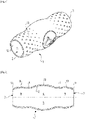
- the manual garlic peeler attachment shown on the figures 1 and 2 comprises a tubular body 1 having a first open end 2, a second open end 3 opposite the first open end 2, and a hollow interior 4 extending from the first open end 2 to the second open end 3.
- the first open end 2 and the second open end 3 are each configured for the introduction of a clove of garlic into the tubular body 1.
- the tubular body 1 is made of flexible material allowing the tubular body 1 to deform under the effect of pressure exerted during use of the garlic peeler accessory.
- the tubular body 1 has for example a wall with a thickness of between 1.5 and 2 mm.
- the tubular body 1 may have a smooth inner face 12 to facilitate cleaning and an at least partially non-smooth outer face 13, to make it easier to hold in the hand.
- the outer face 13 may for example have several series of cavities, as shown in the figure 1 .
- the tubular body 1 is made of food-grade elastomer material, in particular of food-grade silicone material.
- the flexible material of the tubular body 1 has a hardness of between 50 and 65 Shores A, preferably between 55 and 60 Shores A.
- the tubular body 1 has a first section restriction 6 and a second section restriction 7.
- the first section restriction 6 is arranged at a distance from the first open end 2.
- the tubular body 1 provides a first working chamber 5 extending between the first section restriction 6 and the second section restriction 7.
- the first section restriction 6 and the second section restriction 7 are each configured for the introduction of a clove of garlic in the first working chamber 5.
- the first working chamber 5 has a first maximum section 15 arranged between the first section restriction 6 and the second section restriction 7.
- the first working chamber 5 advantageously has a regular curvature with a section decreasing on either side of the first maximum section 15 in the direction of the first section restriction 6 and the second section restriction 7.
- the tubular body 1 has a second working chamber 8 arranged between the first section restriction 6 and the first open end 2.
- the second working chamber 8 is delimited by the first section restriction 6 and by a third section restriction 10 of the tubular body 1.
- the second working chamber 8 is configured to house at least the major part of a clove of garlic.
- the second working chamber 8 has a second maximum section 18 arranged between the first section restriction 6 and the third section restriction 10.
- the second working chamber 8 advantageously has a regular curvature with a section decreasing on either side of the second maximum section 18 towards the first section restriction 6 and the third section restriction 10.
- the first maximum section 15 of the first working chamber 5 is greater than the second maximum section 18 of the second working chamber 8. Furthermore, the third section restriction 10 coincides with the first open end 2.
- the second section restriction 7 is arranged at a distance from the second open end 3.
- the tubular body 1 has a third working chamber 9 arranged between the second section restriction 7 and the second open end 3.
- the third working chamber 9 is delimited by the second section restriction 7 and by a fourth section restriction 11 of the tubular body 1.
- the third working chamber 9 is configured to house at least the major part of a clove of garlic.
- the third working chamber 9 has a maximum third section 19 arranged between the second section restriction 7 and the fourth section restriction 11.
- the third working chamber 9 advantageously has a regular curvature with a section decreasing on either side of the third maximum section 19 in the direction of the second section restriction 7 and the fourth section restriction 11.
- the first maximum section 15 of the first working chamber 5 is greater than the third maximum section 19 of the third working chamber 9
- the fourth section restriction 11 coincides with the second open end 3.
- the second working chamber 8 and the third working chamber 9 are arranged symmetrically with respect to the first working chamber 5.
- the second maximum section 18 and the third section maximum 19 are advantageously identical.
- the tubular body 1 has a geometry of revolution.
- the first section restriction 6 is formed by a first annular constriction
- the second section restriction 7 is formed by a second annular constriction.
- the inner face 12 of the tubular body 1 does not have any internal projection at the level of the first section restriction 6 or of the second section restriction 7, but only a convex curvature, which contributes to facilitating the cleaning of the internal face. 12 of the tubular body 1.
- the first open end 2 is formed by a third annular neck
- the second open end 3 is formed by a fourth annular neck.
- the inner face 12 of the tubular body 1 does not have any internal projection at the level of the third section restriction 10 or the fourth section restriction 11, but only a convex curvature, which contributes to facilitating cleaning of the internal face. 12 of the tubular body 1, but also which contributes to a more homogeneous and more predictable deformation of the tubular body.
- the manual garlic peeler attachment shown on the figures 1 and 2 is used as follows.
- the user introduces at least one clove of garlic into the tubular body 1, through the first open end 2 or through the second open end 3, preferably as far as the first working chamber 5.
- the user positions the tubular body 1 thus filled on a work surface, and rolls it using the palm of the hand.
- the first section restriction 6 and the second section restriction 7 contribute to containing the garlic clove or cloves in the first working chamber 5, while contributing to the peeling, due to the shear stress exerted by the section variation of the tubular body on the skin of the garlic cloves, thanks to the adhesion of the flexible material used for the production of the tubular body 1.
- the second working chamber 8 and the third working chamber 9 make it possible to collect the clove or cloves of garlic escaping from the first working chamber 5, the third section restriction 10 and the fourth section restriction 11 contributing to contain the garlic clove or cloves in the tubular body 1.
- the garlic cloves thus have less tendency to escape from the tubular body 1.
- the structure of the tubular body 1 open at both ends facilitates cleaning of the manual garlic peel accessory. The use of the manual garlic peeler accessory is thus facilitated.
- At least the first open end 2, respectively at least the second open end 3, is configured for the introduction of a garlic clove into the tubular body 1.
- at least the first section restriction 6 , respectively at least the second section restriction 7 is configured for the introduction of a clove of garlic into the first working chamber 5.
- the tubular body 1 does not necessarily have a third working chamber configured to accommodate at least the major part of a clove of garlic.
- the second section restriction 7 can be merged with the second open end 3.
- the second section restriction 7 can extend away from the second open end 3 without however forming a working chamber configured to accommodate at least most of a clove of garlic.
Description
La présente invention concerne de manière générale le domaine des accessoires de préparation culinaire.The present invention generally relates to the field of culinary preparation accessories.
La présente invention concerne plus particulièrement un accessoire pèle-ail manuel prévu pour faciliter le retrait de l'enveloppe extérieure d'une ou de plusieurs gousses d'ail.The present invention relates more particularly to a manual peel-garlic accessory designed to facilitate the removal of the outer envelope of one or more cloves of garlic.
Il est connu du document
Le document
Un objet de la présente invention est de proposer un accessoire pèle-ail manuel du type précité qui soit efficace et facile à utiliser.An object of the present invention is to provide a manual garlic peeler accessory of the aforementioned type which is effective and easy to use.
Un objet de la présente invention est de proposer un accessoire pèle-ail manuel du type précité qui soit facile à réaliser.An object of the present invention is to provide a manual garlic peeler accessory of the aforementioned type which is easy to make.
Ces objets sont atteints avec un accessoire pèle-ail manuel selon la revendication 1. Ainsi lorsqu'une gousse d'ail s'échappe de la première chambre de travail par la première restriction de section, cette gousse d'ail peut être retenue par la troisième restriction de section dans la deuxième chambre de travail, même si une extrémité de ladite gousse d'ail tend à commencer à traverser la première extrémité ouverte. Les gousses d'ail introduites dans le corps tubulaire sont davantage confinées à l'intérieur du corps tubulaire et s'échappent moins par la première extrémité ouverte. La présence de deux extrémités ouvertes facilite la réalisation de l'accessoire ainsi que l'utilisation de l'accessoire. Les deux extrémités ouvertes permettent de mieux contrôler la déformation de l'accessoire lorsque l'utilisateur fait rouler sur un support approprié le corps tubulaire contenant une ou plusieurs gousses d'ail. L'utilisateur peut facilement retirer les gousses d'ail pelées ainsi que les pelures. Le nettoyage est également facilité par la configuration tubulaire de l'accessoire.These objects are achieved with a manual garlic peeler according to claim 1. Thus when a clove of garlic escapes from the first working chamber by the first section restriction, this clove of garlic can be retained by the third section restriction in the second working chamber, even if one end of said garlic clove tends to begin to pass through the first open end. The garlic cloves introduced into the tubular body are more confined within the tubular body and escape less through the first open end. The presence of two open ends facilitates the production of the accessory as well as the use of the accessory. The two open ends make it possible to better control the deformation of the accessory when the user rolls the tubular body containing one or more cloves of garlic on a suitable support. The user can easily remove the peeled garlic cloves as well as the peels. Cleaning is also facilitated by the tubular configuration of the accessory.
La première restriction de section formée par un premier rétreint annulaire permet de faciliter l'utilisation de l'accessoire pèle-ail en rendant plus régulière la déformation de l'accessoire pèle-ail au niveau de la première restriction de section lors du roulement de l'accessoire pèle-ail sur le plan de travail. La deuxième restriction de section formée par un deuxième rétreint annulaire permet de faciliter l'utilisation de l'accessoire pèle-ail en rendant plus régulière la déformation de l'accessoire pèle-ail au niveau de la deuxième restriction de section lors du roulement de l'accessoire pèle-ail sur le plan de travail. La troisième restriction de section confondue avec la première extrémité ouverte permet de simplifier la réalisation de l'accessoire pèle-ail.The first section restriction formed by a first annular shrinkage facilitates the use of the garlic peeler accessory by making the deformation of the garlic peeler accessory more regular at the level of the first section restriction during rolling of the garlic peeler on the work surface. The second section restriction formed by a second annular constriction facilitates the use of the garlic peeler accessory by making the deformation of the garlic peeler accessory more regular at the level of the second section restriction during rolling of the garlic peeler. garlic peeler accessory on the worktop. The third sectional restriction merged with the first open end makes it possible to simplify the production of the garlic peeler accessory.
Avantageusement encore, une première section maximale de la première chambre de travail est supérieure à une deuxième section maximale de la deuxième chambre de travail. L'utilisateur peut ainsi loger préférentiellement la ou les gousses d'ail à éplucher dans la première chambre de travail, et faire rouler l'accessoire en dirigeant préférentiellement la ou les gousses d'ail vers la première restriction séparant la première chambre de travail de la deuxième chambre de travail.Advantageously again, a first maximum section of the first working chamber is greater than a second maximum section of the second working chamber. The user can thus preferentially house the garlic clove or cloves to be peeled in the first working chamber, and roll the accessory by preferentially directing the garlic clove or cloves towards the first restriction separating the first working chamber from the second working chamber.
Avantageusement encore, la deuxième restriction de section est agencée à distance de la deuxième extrémité ouverte, et le corps tubulaire présente une troisième chambre de travail configurée pour loger au moins la majeure partie d'une gousse d'ail, la troisième chambre de travail étant agencée entre la deuxième restriction de section et la deuxième extrémité ouverte, la troisième chambre de travail étant délimitée par la deuxième restriction de section et par une quatrième restriction de section. Cette disposition permet de mieux utiliser la première chambre de travail en facilitant la rétention des gousses d'ail s'échappant de la première chambre de travail par la première restriction de section ou par la deuxième restriction de section. L'utilisateur palpant la présence de gousses d'ail dans la deuxième chambre de travail ou dans la troisième chambre de travail, ou voyant des gousses d'ail commencer à sortir par la première extrémité ouverte ou par la deuxième extrémité ouverte peut adapter la position de sa main sur le corps tubulaire pour ramener lesdites gousses d'ail vers la première chambre de travail.Advantageously again, the second section restriction is arranged at a distance from the second open end, and the tubular body has a third working chamber configured to accommodate at least the major part of a clove of garlic, the third working chamber being arranged between the second section restriction and the second open end, the third working chamber being delimited by the second section restriction and by a fourth section restriction. This arrangement makes it possible to better use the first working chamber by facilitating the retention of the garlic cloves escaping from the first working chamber by the first section restriction or by the second section restriction. The user feeling the presence of garlic cloves in the second working chamber or in the third working chamber, or seeing garlic cloves starting to come out from the first open end or from the second open end can adapt the position with his hand on the tubular body to bring said cloves of garlic back to the first working chamber.
Avantageusement alors, la quatrième restriction de section est confondue avec la deuxième extrémité ouverte. Cette disposition permet de simplifier la réalisation de l'accessoire pèle-ail.Advantageously then, the fourth section restriction coincides with the second open end. This arrangement makes it possible to simplify the production of the garlic-peeler accessory.
Avantageusement encore, une première section maximale de la première chambre de travail est supérieure à une troisième section maximale de la troisième chambre de travail. L'utilisateur peut ainsi loger préférentiellement la ou les gousses d'ail à éplucher dans la première chambre de travail, et faire rouler l'accessoire en dirigeant la ou les gousses d'ail vers la première restriction séparant la première chambre de travail de la deuxième chambre de travail ou vers la deuxième restriction séparant la première chambre de travail de la troisième chambre de travail.Advantageously again, a first maximum section of the first working chamber is greater than a third maximum section of the third working chamber. The user can thus preferentially house the garlic clove or cloves to be peeled in the first working chamber, and roll the accessory by directing the garlic clove or cloves towards the first restriction separating the first working chamber from the second working chamber or towards the second restriction separating the first working chamber from the third working chamber.
Avantageusement encore, la deuxième chambre de travail et la troisième chambre de travail sont agencées de manière symétrique de part et d'autre de la première chambre de travail. Cette disposition permet de simplifier l'utilisation de l'accessoire pèle-ail, la symétrie d'agencement rendant plus prévisible le comportement de l'accessoire pèle-ail lors de sa déformation.Advantageously, the second working chamber and the third working chamber are arranged symmetrically on either side of the first working chamber. This arrangement makes it possible to simplify the use of the garlic peeler accessory, the symmetry of arrangement making the behavior of the garlic peeler accessory more predictable during its deformation.
Avantageusement encore, le corps tubulaire présente une face intérieure lisse. Cette disposition permet de faciliter le nettoyage de l'accessoire pèle-ail. Cette disposition contribue également à simplifier la réalisation de l'accessoire pèle-ail.Advantageously, the tubular body has a smooth inner face. This arrangement makes it easier to clean the garlic peeler accessory. This arrangement also contributes to simplifying the production of the garlic peeler accessory.
Selon une forme de réalisation, le corps tubulaire est réalisé en matériau élastomère de qualité alimentaire.According to one embodiment, the tubular body is made of food grade elastomeric material.
Selon une forme de réalisation, le corps tubulaire est réalisé en matériau silicone de qualité alimentaire.According to one embodiment, the tubular body is made of food grade silicone material.
Selon une forme de réalisation, le matériau flexible du corps tubulaire présente une dureté comprise entre 50 et 65 Shores A, de préférence comprise entre 55 et 60 Shores A.According to one embodiment, the flexible material of the tubular body has a hardness of between 50 and 65 Shores A, preferably between 55 and 60 Shores A.
Avantageusement encore, le corps tubulaire présente une géométrie de révolution. Cette disposition permet de faciliter l'utilisation de l'accessoire pèle-ail en rendant plus régulière la déformation de l'accessoire pèle-ail lors du roulement de l'accessoire pèle-ail sur le plan de travail.Advantageously, the tubular body has a geometry of revolution. This arrangement makes it easier to use the garlic peeler accessory by making the deformation of the garlic peeler accessory more regular when rolling the garlic peeler accessory on the work surface.
Avantageusement encore, le corps tubulaire présente une paroi d'épaisseur comprise entre 1,5 et 2 mm.Advantageously, the tubular body has a wall thickness of between 1.5 and 2 mm.
D'autres caractéristiques et avantages de la présente invention apparaîtront plus clairement à la lecture de la description détaillée qui suit d'un exemple de réalisation, pris à titre nullement limitatif, illustré dans les figures annexées, dans lesquelles :
- La
figure 1 représente une vue en perspective d'un exemple de réalisation d'un accessoire pèle-ail manuel selon l'invention. - La
figure 2 représente une vue en coupe longitudinale de l'exemple de réalisation d'un accessoire pèle-ail manuel selon l'invention illustré sur lafigure 1 .
- The
figure 1 shows a perspective view of an embodiment of a manual garlic peeler accessory according to the invention. - The
picture 2figure 1 .
L'accessoire pèle-ail manuel illustré sur les
Le corps tubulaire 1 est réalisé en matériau flexible permettant au corps tubulaire 1 de se déformer sous l'effet d'une pression exercée lors d'une utilisation de l'accessoire pèle-ail. Le corps tubulaire 1 présente par exemple une paroi d'épaisseur comprise entre 1,5 et 2 mm.The tubular body 1 is made of flexible material allowing the tubular body 1 to deform under the effect of pressure exerted during use of the garlic peeler accessory. The tubular body 1 has for example a wall with a thickness of between 1.5 and 2 mm.
Le corps tubulaire 1 peut présenter une face intérieure 12 lisse pour faciliter le nettoyage et une face extérieure 13 au moins partiellement non lisse, pour faciliter la tenue en main. La face extérieure 13 peut présenter par exemple plusieurs séries de cavité, tel que représenté sur la
Le corps tubulaire 1 est réalisé en matériau élastomère de qualité alimentaire, notamment en matériau silicone de qualité alimentaire. Avantageusement, le matériau flexible du corps tubulaire 1 présente une dureté comprise entre 50 et 65 Shores A, de préférence comprise entre 55 et 60 Shores A.The tubular body 1 is made of food-grade elastomer material, in particular of food-grade silicone material. Advantageously, the flexible material of the tubular body 1 has a hardness of between 50 and 65 Shores A, preferably between 55 and 60 Shores A.
Tel que mieux visible sur la
Le corps tubulaire 1 ménage une première chambre de travail 5 s'étendant entre la première restriction de section 6 et la deuxième restriction de section 7. La première restriction de section 6 et la deuxième restriction de section 7 sont chacune configurée pour l'introduction d'une gousse d'ail dans la première chambre de travail 5. La première chambre de travail 5 présente une première section maximale 15 agencée entre la première restriction de section 6 et la deuxième restriction de section 7. La première chambre de travail 5 présente avantageusement une courbure régulière avec une section diminuant de part et d'autre de la première section maximale 15 en direction de la première restriction de section 6 et de la deuxième restriction de section 7.The tubular body 1 provides a first
Tel que bien visible sur la
Plus particulièrement dans l'exemple de réalisation illustré sur les figures, la première section maximale 15 de la première chambre de travail 5 est supérieure à la deuxième section maximale 18 de la deuxième chambre de travail 8. Par ailleurs, la troisième restriction de section 10 est confondue avec la première extrémité ouverte 2.More particularly in the embodiment illustrated in the figures, the first
Plus particulièrement dans l'exemple de réalisation illustré sur les figures, la deuxième restriction de section 7 est agencée à distance de la deuxième extrémité ouverte 3. Le corps tubulaire 1 présente une troisième chambre de travail 9 agencée entre la deuxième restriction de section 7 et la deuxième extrémité ouverte 3. La troisième chambre de travail 9 est délimitée par la deuxième restriction de section 7 et par une quatrième restriction de section 11 du corps tubulaire 1. La troisième chambre de travail 9 est configurée pour loger au moins la majeure partie d'une gousse d'ail. La troisième chambre de travail 9 présente une troisième section maximale 19 agencée entre la deuxième restriction de section 7 et la quatrième restriction de section 11. La troisième chambre de travail 9 présente avantageusement une courbure régulière avec une section diminuant de part et d'autre de la troisième section maximale 19 en direction de la deuxième restriction de section 7 et de la quatrième restriction de section 11. La première section maximale 15 de la première chambre de travail 5 est supérieure à la troisième section maximale 19 de la troisième chambre de travail 9. Par ailleurs, la quatrième restriction de section 11 est confondue avec la deuxième extrémité ouverte 3.More particularly in the embodiment illustrated in the figures, the
Plus particulièrement dans l'exemple de réalisation illustré sur les figures, la deuxième chambre de travail 8 et la troisième chambre de travail 9 sont agencées de manière symétrique par rapport à la première chambre de travail 5. La deuxième section maximale 18 et la troisième section maximale 19 sont avantageusement identiques.More particularly in the embodiment illustrated in the figures, the second working
Plus particulièrement dans l'exemple de réalisation illustré sur les figures, le corps tubulaire 1 présente une géométrie de révolution. La première restriction de section 6 est formée par un premier rétreint annulaire, et la deuxième restriction de section 7 est formée par un deuxième rétreint annulaire. Ainsi la face intérieure 12 du corps tubulaire 1 ne présente pas de saillie interne au niveau de la première restriction de section 6 ou de la deuxième restriction de section 7, mais seulement une courbure convexe, ce qui contribue à faciliter le nettoyage de la face intérieure 12 du corps tubulaire 1. La première extrémité ouverte 2 est formée par un troisième rétreint annulaire, et la deuxième extrémité ouverte 3 est formée par un quatrième rétreint annulaire. Ainsi la face intérieure 12 du corps tubulaire 1 ne présente pas de saillie interne au niveau de la troisième restriction de section 10 ou de la quatrième restriction de section 11, mais seulement une courbure convexe, ce qui contribue à faciliter le nettoyage de la face intérieure 12 du corps tubulaire 1, mais aussi ce qui contribue à une déformation plus homogène et plus prévisible du corps tubulaire.More particularly in the embodiment illustrated in the figures, the tubular body 1 has a geometry of revolution. The first section restriction 6 is formed by a first annular constriction, and the
L'accessoire pèle-ail manuel illustré sur les
A titre de variante, au moins la première extrémité ouverte 2, respectivement au moins la deuxième extrémité ouverte 3, est configurée pour l'introduction d'une gousse d'ail dans le corps tubulaire 1. Alors au moins la première restriction de section 6, respectivement au moins la deuxième restriction de section 7 est configurée pour l'introduction d'une gousse d'ail dans la première chambre de travail 5.Alternatively, at least the first
A titre de variante, le corps tubulaire 1 ne présente pas nécessairement une troisième chambre de travail configurée pour loger au moins la majeure partie d'une gousse d'ail. Si désiré, la deuxième restriction de section 7 peut être confondue avec la deuxième extrémité ouverte 3. En alternative, la deuxième restriction de section 7 peut s'étendre à distance de la deuxième extrémité ouverte 3 sans pour autant former une chambre de travail configurée pour loger au moins la majeure partie d'une gousse d'ail.As a variant, the tubular body 1 does not necessarily have a third working chamber configured to accommodate at least the major part of a clove of garlic. If desired, the
La présente invention n'est nullement limitée à l'exemple de réalisation décrit et à ses variantes, mais englobe de nombreuses modifications dans le cadre des revendications.The present invention is in no way limited to the embodiment described and its variants, but encompasses numerous modifications within the scope of the claims.
Claims (13)
- Manual garlic peeling accessory comprising a tubular body (1) having a first open end (2), a second open end (3) opposite the first open end (2), and a hollow interior (4) extending from the first open end (2) to the second open end (3), the tubular body (1) being made of a flexible material allowing the tubular body (1) to deform under the effect of pressure exerted when the garlic peeling accessory is used, the tubular body (1) having a first working chamber (5) configured to accommodate at least one garlic clove, the tubular body (1) having a first cross-sectional restriction (6) arranged at a distance from the first open end (2) and a second cross-sectional restriction (7), the first working chamber (5) extending between the first cross-sectional restriction (6) and the second cross-sectional restriction (7), the tubular body (1) having a second working chamber (8) configured to accommodate at least the majority of a garlic clove, the second working chamber (8) being arranged between the first cross-sectional restriction (6) and the first open end (2), the second working chamber (8) being delimited by the first cross-sectional restriction (6) and by a third cross-sectional restriction (10), characterised in that the first cross-sectional restriction (6) is formed by a first annular constriction, in that the second cross-sectional restriction (7) is formed by a second annular constriction, in that the third cross-sectional restriction (10) is merged with the first open end (2), and in that the first open end (2) is formed by a third annular constriction.
- Manual garlic peeling accessory according to claim 1, characterised in that a first maximum cross-section (15) of the first working chamber (5) is greater than a second maximum cross-section (18) of the second working chamber (8).
- Manual garlic peeling accessory according to any of claims 1 or 2, characterised in that the second cross-sectional restriction (7) is arranged at a distance from the second open end (3), and in that the tubular body (1) has a third working chamber (9) configured to accommodate at least the majority of a garlic clove, the third working chamber (9) being arranged between the second cross-sectional restriction (7) and the second open end (3), the third working chamber (9) being delimited by the second cross-sectional restriction (7) and by a fourth cross-sectional restriction (11).
- Manual garlic peeling accessory according to claim 3, characterised in that the fourth cross-sectional restriction (11) is merged with the second open end (3).
- Manual garlic peeling accessory according to any of claims 3 or 4, characterised in that a first maximum cross-section (15) of the first working chamber (5) is greater than a third maximum cross-section (19) of the third working chamber (9).
- Manual garlic peeling accessory according to any of claims 3 to 5, characterised in that the second working chamber (8) and the third working chamber (9) are arranged symmetrically on either side of the first working chamber (5).
- Manual garlic peeling accessory according to any of claims 1 to 6, characterised in that the second open end (3) is formed by a fourth annular constriction.
- Manual garlic peeling accessory according to any of claims 1 to 7, characterised in that the tubular body (1) has a smooth inner face (12).
- Manual garlic peeling accessory according to any of claims 1 to 8, characterised in that the tubular body (1) is made of food-grade elastomer material.
- Manual garlic peeling accessory according to any of claims 1 to 9, characterised in that the tubular body (1) is made of food-grade silicone material.
- Manual garlic peeling accessory according to any of claims 1 to 10, characterised in that the flexible material of the tubular body (1) has a hardness of between 50 and 65 Shore A, preferably between 55 and 60 Shore A.
- Manual garlic peeling accessory according to any of claims 1 to 11, characterised in that the tubular body (1) has a geometry of revolution.
- Manual garlic peeling accessory according to any of claims 1 to 12, characterised in that the tubular body (1) has a wall with a thickness of between 1.5 and 2 mm.
Applications Claiming Priority (1)
| Application Number | Priority Date | Filing Date | Title |
|---|---|---|---|
| FR1902626A FR3093629B1 (en) | 2019-03-14 | 2019-03-14 | MANUAL GARLIC PEELER ACCESSORY |
Publications (2)
| Publication Number | Publication Date |
|---|---|
| EP3708035A1 EP3708035A1 (en) | 2020-09-16 |
| EP3708035B1 true EP3708035B1 (en) | 2022-04-27 |
Family
ID=67384000
Family Applications (1)
| Application Number | Title | Priority Date | Filing Date |
|---|---|---|---|
| EP20162869.0A Active EP3708035B1 (en) | 2019-03-14 | 2020-03-13 | Manual garlic peeling accessory |
Country Status (3)
| Country | Link |
|---|---|
| EP (1) | EP3708035B1 (en) |
| CN (1) | CN111685571B (en) |
| FR (1) | FR3093629B1 (en) |
Family Cites Families (10)
| Publication number | Priority date | Publication date | Assignee | Title |
|---|---|---|---|---|
| US5573803A (en) | 1994-06-06 | 1996-11-12 | Omessi; Benjamin | Vegetable peeler |
| GB2315990A (en) * | 1996-08-03 | 1998-02-18 | Benjamin Beveridge | Hand operated garlic peeler |
| CN2593691Y (en) * | 2003-01-20 | 2003-12-24 | 王建鹏 | Garlic clove peeler |
| CN100558250C (en) * | 2004-08-05 | 2009-11-11 | 梯库姆高新消费品配送股份有限公司 | Garlic peeler |
| CN2778134Y (en) * | 2005-03-01 | 2006-05-10 | 王长林 | Garlic peeling implement |
| CN201295119Y (en) * | 2008-07-24 | 2009-08-26 | 浙江苏泊尔橡塑制品有限公司 | Garlic peeler |
| KR101591514B1 (en) * | 2013-11-13 | 2016-02-03 | 최병철 | Peeling apparatus for garlic |
| WO2015116546A1 (en) * | 2014-01-28 | 2015-08-06 | Garlic Shaker, Inc. | Produce shaker |
| CN204683289U (en) | 2015-05-27 | 2015-10-07 | 郑珂 | Palm magnetic massage Garlic peeler |
| US10888190B2 (en) * | 2016-07-13 | 2021-01-12 | Progressive International Corporation | Flexible tubular garlic peeler having a rigid pick |
-
2019
- 2019-03-14 FR FR1902626A patent/FR3093629B1/en active Active
-
2020
- 2020-03-13 CN CN202010173646.5A patent/CN111685571B/en active Active
- 2020-03-13 EP EP20162869.0A patent/EP3708035B1/en active Active
Also Published As
| Publication number | Publication date |
|---|---|
| FR3093629A1 (en) | 2020-09-18 |
| EP3708035A1 (en) | 2020-09-16 |
| CN111685571A (en) | 2020-09-22 |
| CN111685571B (en) | 2023-08-08 |
| FR3093629B1 (en) | 2022-02-18 |
Similar Documents
| Publication | Publication Date | Title |
|---|---|---|
| CA2639892C (en) | Hollow kitchen utensil handle | |
| FR2855420A3 (en) | Ear stoppers for use in swimming to prevent water from entering the ear are made from one-piece rubber and have protector (30) which fits into an ear canal | |
| CA3056322A1 (en) | Syringe with optimised centre of gravity | |
| FR2698781A1 (en) | Device intended to remedy light urinary incontinence in women. | |
| EP3708035B1 (en) | Manual garlic peeling accessory | |
| FR2916135A1 (en) | Manual cleaning utensil for e.g. nostril of nose, has unit adjusting curve or bending of vanes, where position of unit determines configuration of functional part, and displacement of unit drives modification of curve shape of vanes | |
| FR2947153A1 (en) | INTERCHANGEABLE ENVELOPE FOR HELMETS AND HELMETS PROVIDED WITH SUCH AN ENVELOPE, TO MITIGATE THE TRAUMATING EFFECTS OF ROTATIONAL SHOCK | |
| FR2834447A3 (en) | Ear stopper for swimmers has void terminating in a sound diaphragm | |
| WO1991012841A1 (en) | Syringe with retractable needle | |
| FR2886709A1 (en) | Medical liquid transferring connector, has valve with elastomer skirt, case comprising conduit with small and large diameter sections, and fixed nozzle that slides in cover of valve without penetrating in valve slot | |
| FR2990353A1 (en) | Protection device for needle of hypodermic syringe, has cover including resiliently deformable peripheral wall to be able to assume extended position in which cover covers entire zone occupied by needle for protection of needle | |
| EP2782520B1 (en) | Toothbrush apparatus having multiple rotatable brushing systems | |
| BE1021827B1 (en) | FRUIT OR VEGETABLE FACTOR | |
| CH359330A (en) | Connection of tubular elements | |
| FR2886954A3 (en) | Guard for bathroom shower hose or pipe consists of one or more bead-like bodies with a central aperture for the hose or pipe | |
| FR3060300A1 (en) | MASSAGE DEVICE | |
| BE1023098B1 (en) | REMOVABLE HANDLE FOR UTENSILS | |
| FR3136341A1 (en) | Cosmetic product application brush with deformable handle | |
| WO2019170975A1 (en) | Applicator device for a cosmetic product | |
| EP1495701B1 (en) | Joining element for cooking untensil called couscous vessel | |
| EP1589854B1 (en) | Pillow of the type comprising a central core | |
| FR3109071A1 (en) | Adjustable cosmetic sets and applicators | |
| EP0544901A1 (en) | Releasable sealed attachment of a boot or glove to the free end of the corresponding portion of a protective garment. | |
| FR3060973A1 (en) | USTENSILE A HAND FOR MANUAL MASSAGE OF THE FACE HAVING A COMBINATION OF BODY MASSING | |
| EP3662768A1 (en) | Multifunctional safety cutting tool and consumption kit comprising such a tool |
Legal Events
| Date | Code | Title | Description |
|---|---|---|---|
| PUAI | Public reference made under article 153(3) epc to a published international application that has entered the european phase |
Free format text: ORIGINAL CODE: 0009012 |
|
| STAA | Information on the status of an ep patent application or granted ep patent |
Free format text: STATUS: THE APPLICATION HAS BEEN PUBLISHED |
|
| AK | Designated contracting states |
Kind code of ref document: A1 Designated state(s): AL AT BE BG CH CY CZ DE DK EE ES FI FR GB GR HR HU IE IS IT LI LT LU LV MC MK MT NL NO PL PT RO RS SE SI SK SM TR |
|
| AX | Request for extension of the european patent |
Extension state: BA ME |
|
| STAA | Information on the status of an ep patent application or granted ep patent |
Free format text: STATUS: REQUEST FOR EXAMINATION WAS MADE |
|
| 17P | Request for examination filed |
Effective date: 20210315 |
|
| RBV | Designated contracting states (corrected) |
Designated state(s): AL AT BE BG CH CY CZ DE DK EE ES FI FR GB GR HR HU IE IS IT LI LT LU LV MC MK MT NL NO PL PT RO RS SE SI SK SM TR |
|
| STAA | Information on the status of an ep patent application or granted ep patent |
Free format text: STATUS: EXAMINATION IS IN PROGRESS |
|
| 17Q | First examination report despatched |
Effective date: 20210428 |
|
| GRAP | Despatch of communication of intention to grant a patent |
Free format text: ORIGINAL CODE: EPIDOSNIGR1 |
|
| STAA | Information on the status of an ep patent application or granted ep patent |
Free format text: STATUS: GRANT OF PATENT IS INTENDED |
|
| INTG | Intention to grant announced |
Effective date: 20211207 |
|
| GRAS | Grant fee paid |
Free format text: ORIGINAL CODE: EPIDOSNIGR3 |
|
| GRAA | (expected) grant |
Free format text: ORIGINAL CODE: 0009210 |
|
| STAA | Information on the status of an ep patent application or granted ep patent |
Free format text: STATUS: THE PATENT HAS BEEN GRANTED |
|
| AK | Designated contracting states |
Kind code of ref document: B1 Designated state(s): AL AT BE BG CH CY CZ DE DK EE ES FI FR GB GR HR HU IE IS IT LI LT LU LV MC MK MT NL NO PL PT RO RS SE SI SK SM TR |
|
| REG | Reference to a national code |
Ref country code: GB Ref legal event code: FG4D Free format text: NOT ENGLISH |
|
| REG | Reference to a national code |
Ref country code: CH Ref legal event code: EP |
|
| REG | Reference to a national code |
Ref country code: AT Ref legal event code: REF Ref document number: 1486263 Country of ref document: AT Kind code of ref document: T Effective date: 20220515 |
|
| REG | Reference to a national code |
Ref country code: DE Ref legal event code: R096 Ref document number: 602020002789 Country of ref document: DE |
|
| REG | Reference to a national code |
Ref country code: IE Ref legal event code: FG4D Free format text: LANGUAGE OF EP DOCUMENT: FRENCH |
|
| REG | Reference to a national code |
Ref country code: LT Ref legal event code: MG9D |
|
| REG | Reference to a national code |
Ref country code: NL Ref legal event code: MP Effective date: 20220427 |
|
| REG | Reference to a national code |
Ref country code: AT Ref legal event code: MK05 Ref document number: 1486263 Country of ref document: AT Kind code of ref document: T Effective date: 20220427 |
|
| PG25 | Lapsed in a contracting state [announced via postgrant information from national office to epo] |
Ref country code: NL Free format text: LAPSE BECAUSE OF FAILURE TO SUBMIT A TRANSLATION OF THE DESCRIPTION OR TO PAY THE FEE WITHIN THE PRESCRIBED TIME-LIMIT Effective date: 20220427 |
|
| PG25 | Lapsed in a contracting state [announced via postgrant information from national office to epo] |
Ref country code: SE Free format text: LAPSE BECAUSE OF FAILURE TO SUBMIT A TRANSLATION OF THE DESCRIPTION OR TO PAY THE FEE WITHIN THE PRESCRIBED TIME-LIMIT Effective date: 20220427 Ref country code: PT Free format text: LAPSE BECAUSE OF FAILURE TO SUBMIT A TRANSLATION OF THE DESCRIPTION OR TO PAY THE FEE WITHIN THE PRESCRIBED TIME-LIMIT Effective date: 20220829 Ref country code: NO Free format text: LAPSE BECAUSE OF FAILURE TO SUBMIT A TRANSLATION OF THE DESCRIPTION OR TO PAY THE FEE WITHIN THE PRESCRIBED TIME-LIMIT Effective date: 20220727 Ref country code: LT Free format text: LAPSE BECAUSE OF FAILURE TO SUBMIT A TRANSLATION OF THE DESCRIPTION OR TO PAY THE FEE WITHIN THE PRESCRIBED TIME-LIMIT Effective date: 20220427 Ref country code: HR Free format text: LAPSE BECAUSE OF FAILURE TO SUBMIT A TRANSLATION OF THE DESCRIPTION OR TO PAY THE FEE WITHIN THE PRESCRIBED TIME-LIMIT Effective date: 20220427 Ref country code: GR Free format text: LAPSE BECAUSE OF FAILURE TO SUBMIT A TRANSLATION OF THE DESCRIPTION OR TO PAY THE FEE WITHIN THE PRESCRIBED TIME-LIMIT Effective date: 20220728 Ref country code: FI Free format text: LAPSE BECAUSE OF FAILURE TO SUBMIT A TRANSLATION OF THE DESCRIPTION OR TO PAY THE FEE WITHIN THE PRESCRIBED TIME-LIMIT Effective date: 20220427 Ref country code: ES Free format text: LAPSE BECAUSE OF FAILURE TO SUBMIT A TRANSLATION OF THE DESCRIPTION OR TO PAY THE FEE WITHIN THE PRESCRIBED TIME-LIMIT Effective date: 20220427 Ref country code: BG Free format text: LAPSE BECAUSE OF FAILURE TO SUBMIT A TRANSLATION OF THE DESCRIPTION OR TO PAY THE FEE WITHIN THE PRESCRIBED TIME-LIMIT Effective date: 20220727 Ref country code: AT Free format text: LAPSE BECAUSE OF FAILURE TO SUBMIT A TRANSLATION OF THE DESCRIPTION OR TO PAY THE FEE WITHIN THE PRESCRIBED TIME-LIMIT Effective date: 20220427 |
|
| PG25 | Lapsed in a contracting state [announced via postgrant information from national office to epo] |
Ref country code: RS Free format text: LAPSE BECAUSE OF FAILURE TO SUBMIT A TRANSLATION OF THE DESCRIPTION OR TO PAY THE FEE WITHIN THE PRESCRIBED TIME-LIMIT Effective date: 20220427 Ref country code: PL Free format text: LAPSE BECAUSE OF FAILURE TO SUBMIT A TRANSLATION OF THE DESCRIPTION OR TO PAY THE FEE WITHIN THE PRESCRIBED TIME-LIMIT Effective date: 20220427 Ref country code: LV Free format text: LAPSE BECAUSE OF FAILURE TO SUBMIT A TRANSLATION OF THE DESCRIPTION OR TO PAY THE FEE WITHIN THE PRESCRIBED TIME-LIMIT Effective date: 20220427 Ref country code: IS Free format text: LAPSE BECAUSE OF FAILURE TO SUBMIT A TRANSLATION OF THE DESCRIPTION OR TO PAY THE FEE WITHIN THE PRESCRIBED TIME-LIMIT Effective date: 20220827 |
|
| REG | Reference to a national code |
Ref country code: DE Ref legal event code: R097 Ref document number: 602020002789 Country of ref document: DE |
|
| PG25 | Lapsed in a contracting state [announced via postgrant information from national office to epo] |
Ref country code: SM Free format text: LAPSE BECAUSE OF FAILURE TO SUBMIT A TRANSLATION OF THE DESCRIPTION OR TO PAY THE FEE WITHIN THE PRESCRIBED TIME-LIMIT Effective date: 20220427 Ref country code: SK Free format text: LAPSE BECAUSE OF FAILURE TO SUBMIT A TRANSLATION OF THE DESCRIPTION OR TO PAY THE FEE WITHIN THE PRESCRIBED TIME-LIMIT Effective date: 20220427 Ref country code: RO Free format text: LAPSE BECAUSE OF FAILURE TO SUBMIT A TRANSLATION OF THE DESCRIPTION OR TO PAY THE FEE WITHIN THE PRESCRIBED TIME-LIMIT Effective date: 20220427 Ref country code: EE Free format text: LAPSE BECAUSE OF FAILURE TO SUBMIT A TRANSLATION OF THE DESCRIPTION OR TO PAY THE FEE WITHIN THE PRESCRIBED TIME-LIMIT Effective date: 20220427 Ref country code: DK Free format text: LAPSE BECAUSE OF FAILURE TO SUBMIT A TRANSLATION OF THE DESCRIPTION OR TO PAY THE FEE WITHIN THE PRESCRIBED TIME-LIMIT Effective date: 20220427 Ref country code: CZ Free format text: LAPSE BECAUSE OF FAILURE TO SUBMIT A TRANSLATION OF THE DESCRIPTION OR TO PAY THE FEE WITHIN THE PRESCRIBED TIME-LIMIT Effective date: 20220427 |
|
| PLBE | No opposition filed within time limit |
Free format text: ORIGINAL CODE: 0009261 |
|
| STAA | Information on the status of an ep patent application or granted ep patent |
Free format text: STATUS: NO OPPOSITION FILED WITHIN TIME LIMIT |
|
| PG25 | Lapsed in a contracting state [announced via postgrant information from national office to epo] |
Ref country code: AL Free format text: LAPSE BECAUSE OF FAILURE TO SUBMIT A TRANSLATION OF THE DESCRIPTION OR TO PAY THE FEE WITHIN THE PRESCRIBED TIME-LIMIT Effective date: 20220427 |
|
| 26N | No opposition filed |
Effective date: 20230130 |
|
| PGFP | Annual fee paid to national office [announced via postgrant information from national office to epo] |
Ref country code: FR Payment date: 20230320 Year of fee payment: 4 |
|
| PG25 | Lapsed in a contracting state [announced via postgrant information from national office to epo] |
Ref country code: SI Free format text: LAPSE BECAUSE OF FAILURE TO SUBMIT A TRANSLATION OF THE DESCRIPTION OR TO PAY THE FEE WITHIN THE PRESCRIBED TIME-LIMIT Effective date: 20220427 |
|
| PGFP | Annual fee paid to national office [announced via postgrant information from national office to epo] |
Ref country code: DE Payment date: 20230307 Year of fee payment: 4 |
|
| PG25 | Lapsed in a contracting state [announced via postgrant information from national office to epo] |
Ref country code: MC Free format text: LAPSE BECAUSE OF FAILURE TO SUBMIT A TRANSLATION OF THE DESCRIPTION OR TO PAY THE FEE WITHIN THE PRESCRIBED TIME-LIMIT Effective date: 20220427 |
|
| REG | Reference to a national code |
Ref country code: CH Ref legal event code: PL |
|
| REG | Reference to a national code |
Ref country code: BE Ref legal event code: MM Effective date: 20230331 |
|
| PG25 | Lapsed in a contracting state [announced via postgrant information from national office to epo] |
Ref country code: LU Free format text: LAPSE BECAUSE OF NON-PAYMENT OF DUE FEES Effective date: 20230313 |
|
| REG | Reference to a national code |
Ref country code: IE Ref legal event code: MM4A |
|
| PG25 | Lapsed in a contracting state [announced via postgrant information from national office to epo] |
Ref country code: LI Free format text: LAPSE BECAUSE OF NON-PAYMENT OF DUE FEES Effective date: 20230331 Ref country code: IT Free format text: LAPSE BECAUSE OF FAILURE TO SUBMIT A TRANSLATION OF THE DESCRIPTION OR TO PAY THE FEE WITHIN THE PRESCRIBED TIME-LIMIT Effective date: 20220427 Ref country code: IE Free format text: LAPSE BECAUSE OF NON-PAYMENT OF DUE FEES Effective date: 20230313 Ref country code: CH Free format text: LAPSE BECAUSE OF NON-PAYMENT OF DUE FEES Effective date: 20230331 |
|
| PG25 | Lapsed in a contracting state [announced via postgrant information from national office to epo] |
Ref country code: BE Free format text: LAPSE BECAUSE OF NON-PAYMENT OF DUE FEES Effective date: 20230331 |
|
| PGFP | Annual fee paid to national office [announced via postgrant information from national office to epo] |
Ref country code: DE Payment date: 20240307 Year of fee payment: 5 |