EP3708012B1 - Vorrichtung zur aerosolerzeugung und bedienungsverfahren dafür - Google Patents
Vorrichtung zur aerosolerzeugung und bedienungsverfahren dafür Download PDFInfo
- Publication number
- EP3708012B1 EP3708012B1 EP18872139.3A EP18872139A EP3708012B1 EP 3708012 B1 EP3708012 B1 EP 3708012B1 EP 18872139 A EP18872139 A EP 18872139A EP 3708012 B1 EP3708012 B1 EP 3708012B1
- Authority
- EP
- European Patent Office
- Prior art keywords
- aerosol generating
- magnetic force
- case
- heater
- generating device
- Prior art date
- Legal status (The legal status is an assumption and is not a legal conclusion. Google has not performed a legal analysis and makes no representation as to the accuracy of the status listed.)
- Active
Links
Images




Classifications
-
- A—HUMAN NECESSITIES
- A24—TOBACCO; CIGARS; CIGARETTES; SIMULATED SMOKING DEVICES; SMOKERS' REQUISITES
- A24F—SMOKERS' REQUISITES; MATCH BOXES; SIMULATED SMOKING DEVICES
- A24F40/00—Electrically operated smoking devices; Component parts thereof; Manufacture thereof; Maintenance or testing thereof; Charging means specially adapted therefor
- A24F40/40—Constructional details, e.g. connection of cartridges and battery parts
- A24F40/46—Shape or structure of electric heating means
- A24F40/465—Shape or structure of electric heating means specially adapted for induction heating
-
- A—HUMAN NECESSITIES
- A24—TOBACCO; CIGARS; CIGARETTES; SIMULATED SMOKING DEVICES; SMOKERS' REQUISITES
- A24F—SMOKERS' REQUISITES; MATCH BOXES; SIMULATED SMOKING DEVICES
- A24F40/00—Electrically operated smoking devices; Component parts thereof; Manufacture thereof; Maintenance or testing thereof; Charging means specially adapted therefor
- A24F40/50—Control or monitoring
-
- A—HUMAN NECESSITIES
- A24—TOBACCO; CIGARS; CIGARETTES; SIMULATED SMOKING DEVICES; SMOKERS' REQUISITES
- A24B—MANUFACTURE OR PREPARATION OF TOBACCO FOR SMOKING OR CHEWING; TOBACCO; SNUFF
- A24B15/00—Chemical features or treatment of tobacco; Tobacco substitutes, e.g. in liquid form
- A24B15/10—Chemical features of tobacco products or tobacco substitutes
- A24B15/16—Chemical features of tobacco products or tobacco substitutes of tobacco substitutes
- A24B15/167—Chemical features of tobacco products or tobacco substitutes of tobacco substitutes in liquid or vaporisable form, e.g. liquid compositions for electronic cigarettes
-
- A—HUMAN NECESSITIES
- A24—TOBACCO; CIGARS; CIGARETTES; SIMULATED SMOKING DEVICES; SMOKERS' REQUISITES
- A24F—SMOKERS' REQUISITES; MATCH BOXES; SIMULATED SMOKING DEVICES
- A24F40/00—Electrically operated smoking devices; Component parts thereof; Manufacture thereof; Maintenance or testing thereof; Charging means specially adapted therefor
- A24F40/10—Devices using liquid inhalable precursors
-
- A—HUMAN NECESSITIES
- A24—TOBACCO; CIGARS; CIGARETTES; SIMULATED SMOKING DEVICES; SMOKERS' REQUISITES
- A24F—SMOKERS' REQUISITES; MATCH BOXES; SIMULATED SMOKING DEVICES
- A24F40/00—Electrically operated smoking devices; Component parts thereof; Manufacture thereof; Maintenance or testing thereof; Charging means specially adapted therefor
- A24F40/20—Devices using solid inhalable precursors
-
- A—HUMAN NECESSITIES
- A24—TOBACCO; CIGARS; CIGARETTES; SIMULATED SMOKING DEVICES; SMOKERS' REQUISITES
- A24F—SMOKERS' REQUISITES; MATCH BOXES; SIMULATED SMOKING DEVICES
- A24F40/00—Electrically operated smoking devices; Component parts thereof; Manufacture thereof; Maintenance or testing thereof; Charging means specially adapted therefor
- A24F40/40—Constructional details, e.g. connection of cartridges and battery parts
- A24F40/46—Shape or structure of electric heating means
-
- A—HUMAN NECESSITIES
- A24—TOBACCO; CIGARS; CIGARETTES; SIMULATED SMOKING DEVICES; SMOKERS' REQUISITES
- A24F—SMOKERS' REQUISITES; MATCH BOXES; SIMULATED SMOKING DEVICES
- A24F40/00—Electrically operated smoking devices; Component parts thereof; Manufacture thereof; Maintenance or testing thereof; Charging means specially adapted therefor
- A24F40/50—Control or monitoring
- A24F40/51—Arrangement of sensors
-
- A—HUMAN NECESSITIES
- A24—TOBACCO; CIGARS; CIGARETTES; SIMULATED SMOKING DEVICES; SMOKERS' REQUISITES
- A24F—SMOKERS' REQUISITES; MATCH BOXES; SIMULATED SMOKING DEVICES
- A24F40/00—Electrically operated smoking devices; Component parts thereof; Manufacture thereof; Maintenance or testing thereof; Charging means specially adapted therefor
- A24F40/50—Control or monitoring
- A24F40/57—Temperature control
-
- A—HUMAN NECESSITIES
- A24—TOBACCO; CIGARS; CIGARETTES; SIMULATED SMOKING DEVICES; SMOKERS' REQUISITES
- A24F—SMOKERS' REQUISITES; MATCH BOXES; SIMULATED SMOKING DEVICES
- A24F40/00—Electrically operated smoking devices; Component parts thereof; Manufacture thereof; Maintenance or testing thereof; Charging means specially adapted therefor
- A24F40/60—Devices with integrated user interfaces
-
- A—HUMAN NECESSITIES
- A61—MEDICAL OR VETERINARY SCIENCE; HYGIENE
- A61M—DEVICES FOR INTRODUCING MEDIA INTO, OR ONTO, THE BODY; DEVICES FOR TRANSDUCING BODY MEDIA OR FOR TAKING MEDIA FROM THE BODY; DEVICES FOR PRODUCING OR ENDING SLEEP OR STUPOR
- A61M15/00—Inhalators
- A61M15/06—Inhaling appliances shaped like cigars, cigarettes or pipes
-
- A—HUMAN NECESSITIES
- A24—TOBACCO; CIGARS; CIGARETTES; SIMULATED SMOKING DEVICES; SMOKERS' REQUISITES
- A24F—SMOKERS' REQUISITES; MATCH BOXES; SIMULATED SMOKING DEVICES
- A24F40/00—Electrically operated smoking devices; Component parts thereof; Manufacture thereof; Maintenance or testing thereof; Charging means specially adapted therefor
- A24F40/40—Constructional details, e.g. connection of cartridges and battery parts
Definitions
- the present disclosure disclosed by the present application relates to an aerosol generating device and an operation method thereof, and more specifically, to an aerosol generating device for adjusting coupling force between a cover and a case by using magnetic force, and an operation method thereof.
- WO 2017/207435 A1 relates to an electrically operated aerosol-generating system comprising: a main unit comprising a heating portion at an outer surface of the main unit, the heating portion comprising one or more electric heaters; and a tubular aerosol-generating article comprising: a tubular aerosol-forming substrate; and an inner passage, wherein: the inner passage of the tubular aerosol-generating article is configured to receive the heating portion of the main unit; the one or more electric heaters are arranged to heat the tubular aerosol-forming substrate when the tubular aerosol-generating article is received on the heating portion of the main unit; and at least one of the main unit and the tubular aerosol-generating article comprises at least one retaining feature configured to removably retain the tubular aerosol-generating article on the heating portion of the main unit when the tubular aerosol-generating article is received on the heating portion of the main unit.
- WO 2016/141555 A1 relates to an electronic cigarette that comprises a cigarette cartridge, an atomization device and a magnetic force generation device.
- US 2017/119044 A1 relates to a case that includes a drawer within a cover.
- An objective of the present disclosure is to provide an aerosol generating device capable of controlling coupling force of a cover by using magnetic force, and an operation method thereof.
- Another objective of the present disclosure is to provide an aerosol generating device for controlling a current applied to a coil to heat an aerosol generating material or control the coupling force of the cover, and an operation method thereof.
- An aerosol generating device includes a case, a cover having a metallic body and configured to be coupled to the case, a heater configured to heat an aerosol generating material, a magnetic force generator arranged in the case and configured to generate a magnetic force acting on the metallic body according to a current applied thereto, and a controller configured to adjust coupling force between the cover and the case, which is generated by the magnetic force, by controlling the current applied to the magnetic force generator based on an operating state of the heater.
- the controller may control the current applied to the magnetic force generator to strengthen the coupling force.
- the controller may control the current applied to the magnetic force generator to weaken the coupling force.
- the controller may apply a current having a first current value to the magnetic force generator, and when the heater does not heat the aerosol generating material, may apply a current having a second current value smaller than the first current value to the magnetic force generator.
- the second current value may be 0.
- the aerosol generating device may further include an input unit configured to receive a user input for generating aerosol, and when the user input is received through the input unit, the controller may apply a current to the magnetic force generator and then operate the heater.
- the controller may stop applying the current to the magnetic force generator to facilitate separation of the cover and the case.
- the controller may stop a heating operation of the heater and then stop applying the current to the magnetic force generator.
- the aerosol generating device may further include a puff sensor configured to sense a user's puffs, and the condition may be that the number of a user's puffs, detected through the puff sensor, exceeds a preset puff limit.
- condition may be that a time of a heating operation of the heater exceeds a preset time limit.
- the aerosol generating device may further include an input unit configured to receive a user input, and the condition may be that a user input for stopping heating is received through the input unit.
- the aerosol generating device may further include a temperature sensor configured to measure a temperature of the heater, and the condition may be that, after a heating operation of the heater is stopped, a temperature of the heater descends to below a preset temperature limit.
- the aerosol generating device may further include an input unit configured to receive a user input, and when the heater heats the aerosol generating material, the controller may apply a current to the magnetic force generator, and may reheat the heater while maintaining the current applied to the magnetic force generator when the user input for generating aerosol is received through the input unit, after a heating operation of the heater is stopped but before a temperature of the heater that descends to below a preset temperature limit.
- condition may be that a preset standby time elapses after a heating operation of the heater is stopped.
- the aerosol generating device may further include an input unit configured to receive a user input, and when the heater heats the aerosol generating material, the controller may apply a current to the magnetic force generator, and may reheat the heater while maintaining the current applied to the magnetic force generator when the user input for generating aerosol is received through the input unit, after a heating operation of the heater is stopped but before a preset standby time elapses.
- the heater may be arranged on one upper side of the case
- the magnetic force generator may be arranged on another upper side of the case
- the metallic body may be provided on one side of the cover which faces the other upper side of the case when the cover is coupled to an upper portion of the case.
- An aerosol generating device includes a case, a cover having a metallic body and configured to be coupled to the case, a coil arranged in the case and configured to, according to a current applied, generate an induced current in a susceptor to heat an aerosol generating material, or generate magnetic force acting on the metallic body, and a controller configured to adjust coupling force between the cover and the case which is generated by the magnetic force, and a heating state of the aerosol generating material, by controlling the current applied to the coil.
- the controller may adjust the coupling force between the cover and the case based on the heating state of the aerosol generating material.
- the controller may generate magnetic force through the coil to strengthen the coupling force between the cover and the case.
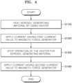
- An operation method of an aerosol generating device is an operation method of an aerosol generating device including a case and a cover couplable to the case, wherein the aerosol generating device includes a metallic body provided in the cover and a magnetic force generator provided in the case and configured to generate magnetic force acting on the metallic body according to a current applied thereto, the operation method including applying a first current to the magnetic force generator to strengthen coupling force between the cover and the case when the aerosol generating material is heated, and applying a second current smaller than the first current to the magnetic force generator to weaken the coupling force, when the aerosol generating material is not heated.
- the operation method of the aerosol generating device may further include receiving a user input for heating the aerosol generating material, applying a current to the magnetic force generator to strengthen the coupling force between the cover and the case, and heating the aerosol generating material after applying the current.
- a user's injury caused in relation to heating of an aerosol generating material may be prevented by adjusting coupling force of a cover by using magnetic force.
- an aerosol generating device may be simply and directly designed by providing a coil which heats the aerosol generating material or adjusts the coupling force of the cover.
- An aerosol generating device includes a case, a cover having a metallic body and being couplable to the case, a heater configured to heat an aerosol generating material, a magnetic force generator arranged in the case and configured to generate magnetic force acting on the metallic body according to a current applied thereto, and a controller configured to adjust coupling force between the cover and the case, which is generated by the magnetic force, by controlling the current applied to the magnetic force generator based on an operating state of the heater, wherein the cover comprises an outer hole aligned with an insertion hole of the case for allowing a cigarette to penetrate the cover through the outer holes and reach the insertion hole of the case.
- An operation method of an aerosol generating device is an operation method of an aerosol generating device including a case and a cover couplable to the case, wherein the aerosol generating device includes a metallic body in the cover and a magnetic force generator, in the case, which generates magnetic force for the metallic body according to a current applied thereto, wherein the cover comprises an outer hole aligned with an insertion hole of the case for allowing a cigarette to penetrate the cover through the outer holes and reach the insertion hole of the case, the operation method including applying a first current to the magnetic force generator to strengthen coupling force between the cover and the case when the aerosol generating material is heated, and applying a second current, which is smaller than the first current, to the magnetic force generator to weaken the coupling force when the aerosol generating material is not heated.
- the general terms which are currently and widely used are selected in consideration of functions of structural elements in the various exemplary embodiments of the present disclosure.
- meanings of the terms can be changed according to intention, a judicial precedence, the appearance of a new technology, and the like.
- a term which is not commonly used can be selected. In such a case, the meaning of the term will be described in detail at the corresponding portion in the description of the present disclosure. Therefore, the terms used in the various exemplary embodiments of the present disclosure should be defined based on the meanings of the terms and the descriptions provided herein.
- aerosol generating material may refer to a material which can generate aerosol, and may also refer to an aerosol forming substrate.
- the aerosol may include a volatile compound.
- the aerosol generating material may be solid or liquid.
- a solid aerosol generating material may include solid materials based on tobacco raw materials such as tobacco sheet cigarettes, pipe tobaccos, reconstituted cigarettes, etc.
- a liquid aerosol generating material may include liquid materials based on nicotine, tobacco extracts, and various flavoring agents.
- the present disclosure is not limited to the above examples.
- the aerosol generating device may be a device for generating aerosol by using an aerosol generating material in order to generate aerosol which can be directly inhaled into a user's lungs through a user's mouth.
- the aerosol generating device may be a holder.
- the term "puff” may refer to inhalation of the user, and the inhalation may refer to a situation in which the user draws air into the user's oral cavity, nasal cavity, or lungs via the user's mouth or nose.
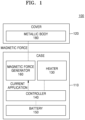
- FIG. 1 is a block diagram of an aerosol generating device according to an exemplary embodiment.
- the aerosol generating device 100 may include a case 110, a cover 120, a heater 130, a magnetic force generator 160, a battery 150, a controller 140, and a metallic body 180 provided in the cover 120.
- the aerosol generating device 100 may heat the heater 130, and an aerosol generating material may be vaporized by the heater 130 to generate aerosol.
- the generated aerosol is delivered to the user by a user's inhalation.
- the case 110 forms a part of an external appearance of the aerosol generating device 100, and functions to accommodate and protect various elements therein.
- the case 110 may include the magnetic force generator 160.
- the case 110 is illustrated as having the magnetic force generator 160, the heater 130, the controller 140, and the battery 150.
- the order and arrangement of the magnetic force generator 160, the heater 130, the controller 140, and the battery 150 illustrated in FIG. 1 may be changed according to the design of the aerosol generating device 100.
- the arrangement of each element is not limited to the inside of the case 110, but may be changed to be arranged outside the case 110, or to be arranged inside or outside the cover 120.
- the cover 120 may be coupled to or separated from the case 110.
- the case 110 and the cover 120 together form the external appearance of the aerosol generating device 100.
- the cover 120 may be coupled to the case 110 to protect internal elements of the aerosol generating device 100.
- the cover 120 When the cover 120 is coupled to the case 110, the cover 120 may prevent heat generated from the heater 130 from being transferred to the outside of the aerosol generating device 100. Accordingly, it is possible to prevent injuries that may occur due to a user inadvertently contacting the heater 130 directly or touching an area of the case 110 heated by the heater 130 during an operation of the heater 130.
- the cover 120 when the cover 120 is coupled to the case 110, the cover 120 may fix the aerosol generating material inserted into and accommodated in the case 110, and thus may prevent the aerosol generating material from being separated from and falling out of the case 110.
- an area of the case 110 that is blocked by the cover 120 while the cover 120 is combined with the case 110 may be exposed to the outside. Accordingly, cleaning of residues of the aerosol generating material or the like may be easily performed.
- the cover 120 may include the metallic body 180.
- Attractive force may be applied to the metallic body 180 in the direction of the magnetic force generator 160 by magnetic force (magnetism) generated by the magnetic force generator 160.
- magnetic force magnetism
- the magnetic force generated by the magnetic force generator 160 may act on the metallic body 180, and thus the coupling force between the cover 120 and the case 110 may be changed.
- the coupling force between the cover 120 and the case 110 may be strengthened, and when the magnetic force is weakened, the coupling force between the cover 120 and the case 110 may be weakened. Accordingly, for the convenience of users or for safety reasons, the cover 120 may be strongly coupled to the case 110, or the cover 120 may be separated from the case 110.
- the heater 130 may be heated by power supplied from the battery 150 to thereby heat and vaporize the aerosol generating material.
- the heater 130 may be any type of heater which can heat aerosol up to a desired temperature for vaporizing aerosol.
- the desired temperature may be set in the aerosol generating device 100 in advance, or may be set by a user.
- the aerosol generating device 100 may temporarily stop a heating operation of the heater 130 or supply a current supplied to the heater 130 in a waveform form in order to maintain the temperature of the heater 130 at a proper temperature.
- the heater 130 may be an electric resistive heater.
- the heater 130 may include an electrically conductive track, and the heater 130 may be heated as a current flows in the electrically conductive track.
- the heater 130 may be an inductive heating-type heater.
- the heater 130 may include an electrically conductive coil 260 for heating the aerosol generating material by using inductive heating
- the cigarette or liquid cartridge may include a susceptor 320 which can be heated by the inductive heating-type heater.
- the magnetic force generator 160 may generate magnetic force (magnetism) according to a command of the controller 140, and may adjust a magnitude of the magnetic force.
- the magnetic force generated by the magnetic force generator 160 may act as an attractive force on the metallic body 180 provided in the cover 120.
- the magnetic force generator 160 may be any electronic device which generates a magnetic force by a current.
- the magnetic force generator 160 may be a solenoid coil, an electromagnet holder, a bipolar electromagnet having both poles provided on one surface thereof together, a unipolar electromagnet having only one pole provided on one surface thereof, a bobbin electromagnet manufactured by winding a coil on an insulator, etc.
- the battery 150 supplies power used to operate the aerosol generating device 100.
- the battery 150 may supply power to heat the heater 130, and may supply power required to operate the controller 140.
- the battery 150 may supply a current to the magnetic force generator 160 according to a command of the controller 140 such that the magnetic force generator 160 may generate magnetic force.
- the battery 150 may supply power required to operate a display, a sensor, a motor, etc. installed in the aerosol generating device 100.
- the controller 140 controls an overall operation of the aerosol generating device 100.
- the controller 140 controls operations of other elements included in the aerosol generating device 100 as well as operations of the battery 150, the heater 130, and the magnetic force generator 160.
- the controller 140 may determine whether the aerosol generating device 100 is in an operable state by checking a state of each element of the aerosol generating device 100.
- the controller 140 may control an operation of the magnetic force generator 160.
- the controller 140 may control the operation of the magnetic force generator 160 by controlling a current applied to the magnetic force generator 160.
- the controller 140 may control the operation of the magnetic force generator 160 based on an operating state of the heater 130.
- the controller 140 may operate the magnetic force generator 160 or may strengthen the magnetic force generated by the magnetic force generator 160, such that the cover 120 is coupled to the case 110 more strongly.
- the controller 140 may stop the operation of the magnetic force generator 160 or may weaken the magnetic force generated by the magnetic force generator 160, such that the cover 120 is easily separable from the case 110. A method, performed by the controller 140, of operating the heater 130 and the magnetic force generator 160 will be described later in more detail.
- the controller 1400 may include at least one processor.
- a processor can be implemented as an array of a plurality of logic gates or can be implemented as a combination of a general-purpose microprocessor and a memory in which a program executable in the microprocessor is stored. It will be understood by one of ordinary skill in the art that the processor can be implemented in other forms of hardware.
- the aerosol generating device 100 may further include general-purpose components in addition to the battery 150, the controller 140, and the heater 130.
- the aerosol generating device 100 may include a display capable of outputting visual information, a motor for outputting haptic information, and/or charging contact for charging battery.
- the motor may notify through vibration that the heating of the heater 130 is completed.
- the aerosol generating device 100 may comprise an LED and display an operating state of the heater 130 through the LED.
- the aerosol generating device 100 may include at least one sensor (a puff detecting sensor, a temperature detecting sensor, a cigarette insertion detecting sensor, etc.).
- the puff detecting sensor may detect puffs in various ways.
- the puffs may be detected by comparing and analyzing a difference between a temperature of introduced air and a temperature inside the aerosol generating device 100.
- the puff detecting sensor may detect the puffs by detecting a change in an air flow inside the aerosol generating device 100, caused by a user's puffs.
- the puff detecting sensor may detect the puffs by a change in resistance of the electrically conductive track that constitutes the heater 130.
- the puff detecting sensor may detect the user's puffs based on a change in a voltage level of the heater 130.
- the controller 140 may determine the presence of a user's puffs and strengths of the puffs through the puff detecting sensor, and may count the number of the puffs.
- the aerosol generating device 100 may include an input unit (not shown). As the input unit is manipulated, the operation of the aerosol generating device 100 may be controlled. For example, the aerosol generating device 100 may receive various inputs through the input unit, such as an input for starting a heating operation, an input for stopping the heating operation, a heating intensity, a heating time, and an intensity of magnetic force generated by the magnetic force generator.
- the input unit may be, for example, a button, a switch, or a touch screen installed on an external surface of the case 110.
- FIG. 2 is a perspective view of an aerosol generating device in which a cover is separated from a case, according to an exemplary embodiment.
- FIGS. 2 and 3 illustrate the aerosol generating device 100 in a case where the aerosol generating material is contained in a cigarette
- the following descriptions made under the assumption that the aerosol generating material is provided in the form of a cigarette may be applied to a case where the aerosol generating material is stored in a liquid cartridge.
- an internal space of the aerosol generating device 100, the heater 130, etc. may be exposed to the outside. Accordingly, a user who finished smoking a cigarette may separate the cigarette from the aerosol generating device 100, and then perform a cleaning operation to remove any tobacco material remaining in the aerosol generating device 100.
- the aerosol generating device 100 may weaken the magnetic force generated by the magnetic force generator 160 such that the cover 120 and the case 110 are easily separable from each other. For example, the aerosol generating device 100 may stop magnetic force generation of the magnetic force generator 160.
- the metallic body 180 and the magnetic force generator 160 may be arranged such that the coupling force between the cover 120 and the case 110 is effectively adjustable due to a change in the magnetic force.
- the heater 130 may be arranged on one upper side of the case 110
- the magnetic force generator 160 may be arranged on the other upper side of the case 110.
- the metallic body 180 may be arranged on one side of the cover 120 facing the other upper side of the case 110 in which the magnetic force generator 160 is arranged.
- Shapes and arrangements of the magnetic force generator 160 and the metallic body 180 are not limited to those illustrated in FIG. 2 .
- the magnetic force generator 160 may be arranged to extend along an upper circumference of the case 110.
- the metallic body may be arranged to extend along a lower circumference of the cover.
- the magnetic force generator 160 may be arranged such that the magnetic force is directed toward the metallic body 180, not toward the controller 140, to minimize the influence of the magnetic force on electronic elements.
- the controller 140 may be arranged in the bottom portion of the case 110, and the magnetic force generator 160 may be arranged in the top portion of the case 110, such that the magnetic force may be directed upward.
- the magnetic force generator 160 and the metallic body 180 may be designed in various shapes such as a rectangular shape, a circular shape, a ring shape, etc.
- the case 110 may have a cigarette receiver 190 formed thereon.
- the heater 130 may be arranged in the cigarette receiver 190, and the heater 130 may heat a cigarette with an aerosol generating material mounted in the cigarette receiver 190.
- the case 110 may have an insertion hole 112 formed in the cigarette receiver 190, and the cigarette may be inserted into the cigarette receiver 190 through the insertion hole 112.
- the cover 120 may have an outer hole 122 aligned with the insertion hole 112 when the case 110 is coupled thereto.
- the cigarette can penetrate the cover 120 through the outer hole and reach the insertion hole 112 of the case 110.
- the cover 120 and the case 110 may be formed of a plastic material that does not transfer heat well, or a metallic material having a heat blocking material coated on surfaces thereof.
- the cover 120 and the case 110 may be manufactured by using, for example, an injection molding method, a three-dimensional (3D) printing method, or a method of assembling small components manufactured by injection molding.
- the shape of the heater 130 is not limited to the shape illustrated in FIG. 2 , and the heater 130 may be manufactured in various shapes.
- the heater 130 may include a tubetype heating element, a plate-type heating element, a needle-type heating element, or a rod-type heating element.
- the heater 130 may heat the inside or the outside of the cigarette according to the shape of the heating element.
- the present disclosure is not limited thereto, and a plurality of heaters 130 may be arranged in the aerosol generating device 100.
- the plurality of heaters 130 may be inserted into the inside of the cigarette or may be arranged outside the cigarette. Also, some of the plurality of heaters 130 may be inserted into the cigarette, and the others may be arranged outside the cigarette.
- the controller 140 and the battery 150 may be arranged under the case 110.
- the controller 140 and the battery 150 may extend in one direction, and may be arranged to extend along an extension direction of the case 110.
- the battery 150 may be charged by receiving power from the outside through a terminal formed under the case 110.
Landscapes
- Engineering & Computer Science (AREA)
- Health & Medical Sciences (AREA)
- Human Computer Interaction (AREA)
- Life Sciences & Earth Sciences (AREA)
- General Health & Medical Sciences (AREA)
- Biomedical Technology (AREA)
- Heart & Thoracic Surgery (AREA)
- Hematology (AREA)
- Pulmonology (AREA)
- Animal Behavior & Ethology (AREA)
- Anesthesiology (AREA)
- Public Health (AREA)
- Veterinary Medicine (AREA)
- Bioinformatics & Cheminformatics (AREA)
- Chemical & Material Sciences (AREA)
- Chemical Kinetics & Catalysis (AREA)
- General Chemical & Material Sciences (AREA)
- Disinfection, Sterilisation Or Deodorisation Of Air (AREA)
- Containers And Packaging Bodies Having A Special Means To Remove Contents (AREA)
Claims (15)
- Aerosolerzeugungsvorrichtung, die Folgendes umfasst:ein Gehäuse (110);eine Abdeckung (120), die einen metallischen Körper (180) aufweist und so konfiguriert ist, dass sie mit dem Gehäuse (110) gekoppelt wird;eine Heizeinrichtung (130), die konfiguriert ist, ein Aerosolerzeugungsmaterial zu erhitzen;einen Magnetkraftgenerator (160), der im Gehäuse (110) angeordnet ist und konfiguriert ist, entsprechend einem zugeführten Strom eine Magnetkraft zu erzeugen, die auf den metallischen Körper (180) wirkt; undeine Steuereinheit (140), die konfiguriert ist, die Kopplungskraft zwischen der Abdeckung (120) und dem Gehäuse (110), die durch die Magnetkraft erzeugt wird, durch Steuern des Stroms, der dem Magnetkraftgenerator (160) zugeführt wird, auf der Basis eines Betriebszustands der Heizeinrichtung (130) anzupassen,dadurch gekennzeichnet, dassdie Abdeckung (120) ein Außenloch (122) umfasst, das auf ein Einsetzloch (112) des Gehäuses (110) ausgerichtet ist, damit eine Zigarette durch das Außenloch (122) durch die Abdeckung (120) hindurch verlaufen und das Einsetzloch (112) des Gehäuses (110) erreichen kann.
- Aerosolerzeugungsvorrichtung nach Anspruch 1, wobei die Steuereinheit (140) konfiguriert ist, den Strom, der dem Magnetkraftgenerator (160) zugeführt wird, zu steuern, um basierend darauf, dass die Heizeinrichtung (130) das Aerosolerzeugungsmaterial erhitzt, die Kopplungskraft zu verstärken, oder wobei die Steuereinheit (140) konfiguriert ist, den Strom, der dem Magnetkraftgenerator (160) zugeführt wird, zu steuern, um basierend darauf, dass die Heizeinrichtung (130) das Aerosolerzeugungsmaterial nicht erhitzt, die Kopplungskraft abzuschwächen.
- Aerosolerzeugungsvorrichtung nach Anspruch 1, wobei die Steuereinheit (140) konfiguriert ist zum:Zuführen eines Stroms, der einen ersten Stromwert hat, zum Magnetkraftgenerator (160) basierend darauf, dass die Heizeinrichtung (130) das Aerosolerzeugungsmaterial erhitzt, undZuführen eines Stroms, der einen zweiten Stromwert hat, der kleiner als der erste Stromwert ist, zum Magnetkraftgenerator (160) basierend darauf, dass die Heizeinrichtung das Aerosolerzeugungsmaterial nicht erhitzt, wobei der zweite Stromwert vorzugsweise null ist.
- Aerosolerzeugungsvorrichtung nach Anspruch 1, die ferner eine Eingabeeinheit umfasst, die konfiguriert ist, eine Benutzereingabe zum Erzeugen von Aerosol zu erhalten,
wobei die Steuereinheit (140) konfiguriert ist, entsprechend der Benutzereingabe, die durch die Eingabeeinheit erhalten wird, nach dem Zuführen des Stroms zum Magnetkraftgenerator (160) die Heizeinrichtung (130) zu betreiben. - Aerosolerzeugungsvorrichtung nach Anspruch 1, wobei der Magnetkraftgenerator (160) eine Magnetspule, einen Elektromagneten oder eine Kombination davon umfasst.
- Aerosolerzeugungsvorrichtung nach Anspruch 1, wobei die Steuereinheit (140) konfiguriert ist, das Zuführen des Stroms zum Magnetkraftgenerator (160) zu stoppen, um die Trennung der Abdeckung (120) und des Gehäuses (110) zu ermöglichen, basierend darauf, dass eine zuvor eingestellte Bedingung erfüllt ist.
- Aerosolerzeugungsvorrichtung nach Anspruch 6, wobei die Steuereinheit (140) konfiguriert ist, basierend darauf, dass die zuvor eingestellte Bedingung erfüllt ist, das Zuführen des Stroms zum Magnetkraftgenerator (160) zu stoppen, nachdem ein Heizbetrieb der Heizeinrichtung (130) gestoppt worden ist.
- Aerosolerzeugungsvorrichtung nach Anspruch 6, die ferner einen Zugsensor umfasst, der konfiguriert ist, den Zug eines Benutzers zu erfassen, wobei die zuvor eingestellte Bedingung darin besteht, dass die Anzahl von Zügen eines Benutzers, die durch den Zugsensor detektiert wird, eine zuvor eingestellte Zuggrenze überschreitet.
- Aerosolerzeugungsvorrichtung nach Anspruch 6, wobei die zuvor eingestellte Bedingung darin besteht, dass eine Zeit eines Heizbetriebs der Heizeinrichtung (130) eine zuvor eingestellte Zeitgrenze überschreitet, und/oder die zuvor eingestellte Bedingung darin besteht, dass eine zuvor eingestellte Standby-Zeit verstrichen ist, nachdem ein Heizbetrieb der Heizeinrichtung (130) gestoppt worden ist.
- Aerosolerzeugungsvorrichtung nach Anspruch 6, die ferner eine Eingabeeinheit umfasst, die konfiguriert ist, eine Benutzereingabe zu erhalten, wobei die zuvor eingestellte Bedingung darin besteht, dass eine Benutzereingabe zum Stoppen des Heizens durch die Eingabeeinheit erhalten wird.
- Aerosolerzeugungsvorrichtung nach Anspruch 6, die ferner einen Temperatursensor umfasst, der konfiguriert ist, eine Temperatur der Heizeinrichtung (130) zu messen, wobei die zuvor eingestellte Bedingung darin besteht, dass dann, nachdem ein Heizbetrieb der Heizeinrichtung (130) gestoppt worden ist, eine Temperatur der Heizeinrichtung (130) unter eine zuvor eingestellte Temperaturgrenze sinkt.
- Aerosolerzeugungsvorrichtung nach Anspruch 1, die ferner eine Eingabeeinheit umfasst, die konfiguriert ist, eine Benutzereingabe zu erhalten, wobei die Steuereinheit (140) konfiguriert ist zum:Zuführen des Stroms zum Magnetkraftgenerator (160) basierend darauf, dass die Heizeinrichtung (130) das Aerosolerzeugungsmaterial erhitzt, underneuten Heizen der Heizeinrichtung (130), während der Strom, der dem Magnetkraftgenerator (160) zugeführt wird, entsprechend der Benutzereingabe zum Erzeugen von Aerosol, die durch die Eingabeeinheit erhalten wurde, aufrechterhalten wird, nachdem ein Heizbetrieb der Heizeinrichtung (130) gestoppt worden ist, j edoch bevor eine Temperatur der Heizeinrichtung (130) unter eine zuvor eingestellte Temperaturgrenze sinkt.
- Aerosolerzeugungsvorrichtung nach Anspruch 1, wobeidie Heizeinrichtung (130) an einer oberen Seite des Gehäuses (110) angeordnet ist,der Magnetkraftgenerator (160) an einer anderen oberen Seite des Gehäuses (110) angeordnet ist, undder metallische Körper (180) an einer Seite der Abdeckung (120) vorgesehen ist, die zur anderen oberen Seite des Gehäuses (110) zeigt, wenn die Abdeckung (110) mit einem oberen Abschnitt des Gehäuses (110) gekoppelt ist.
- Aerosolerzeugungsvorrichtung nach Anspruch 1, wobeiein Magnetkraftgenerator (160) eine Spule umfasst,und die Spule konfiguriert ist, entsprechend einem Strom, der der Spule (260) zugeführt wird, ein Aerosolerzeugungsmaterial zu erhitzen oder durch Erzeugen eines induzierten Stroms in einer Empfängerspule (320) eine Magnetkraft zu erzeugen, die auf den metallischen Körper (180) wirkt, unddie Steuereinheit (140) konfiguriert ist, die Kopplungskraft zwischen der Abdeckung (120) und dem Gehäuse (110) durch die Magnetkraft anzupassen, und einen Heizzustand des Aerosolerzeugungsmaterials durch Steuern des Stroms, der der Spule (260) zugeführt wird, anzupassen.
- Verfahren zum Betreiben einer Aerosolerzeugungsvorrichtung, die ein Gehäuse (110) und eine Abdeckung (120), die mit dem Gehäuse (110) gekoppelt werden kann, umfasst,wobei die Aerosolerzeugungsvorrichtung (100) einen metallischen Körper (180), der in der Abdeckung (120) vorgesehen ist, und einen Magnetkraftgenerator (160), der im Gehäuse (110) vorgesehen ist und konfiguriert ist, entsprechend einem Strom, der zugeführt wird, eine Magnetkraft zu erzeugen, die auf den Festkörper wirkt, umfasst,wobei die Abdeckung (120) ein Außenloch (122), das auf das Einsetzloch (112) des Gehäuses (110) ausgerichtet ist, umfasst, damit eine Zigarette durch das Außenloch (122) durch die Abdeckung (120) verlaufen und das Einsetzloch (112) des Gehäuses (110) erreichen kann, undwobei das Verfahren zum Betreiben die folgenden Schritte umfasst:Stärken der Kopplungskraft zwischen der Abdeckung (110) und dem Gehäuse (120) durch Zuführen eines ersten Stroms zum Magnetkraftgenerator (160), basierend darauf, dass das Aerosolerzeugungsmaterial erhitzt wird; undSchwächen der Kopplungskraft durch Zuführen eines zweiten Stroms, der kleiner als der erste Strom ist, zum Magnetkraftgenerator (160), basierend darauf, dass das Aerosolerzeugungsmaterial nicht erhitzt wird.
Applications Claiming Priority (4)
| Application Number | Priority Date | Filing Date | Title |
|---|---|---|---|
| KR20170146974 | 2017-11-06 | ||
| KR20180007797 | 2018-01-22 | ||
| KR1020180119997A KR102101939B1 (ko) | 2017-11-06 | 2018-10-08 | 에어로졸 생성 장치 및 그 동작 방법 |
| PCT/KR2018/012880 WO2019088605A2 (ko) | 2017-11-06 | 2018-10-29 | 에어로졸 생성 장치 및 그 동작 방법 |
Publications (3)
| Publication Number | Publication Date |
|---|---|
| EP3708012A2 EP3708012A2 (de) | 2020-09-16 |
| EP3708012A4 EP3708012A4 (de) | 2021-08-18 |
| EP3708012B1 true EP3708012B1 (de) | 2025-01-15 |
Family
ID=66579956
Family Applications (1)
| Application Number | Title | Priority Date | Filing Date |
|---|---|---|---|
| EP18872139.3A Active EP3708012B1 (de) | 2017-11-06 | 2018-10-29 | Vorrichtung zur aerosolerzeugung und bedienungsverfahren dafür |
Country Status (5)
| Country | Link |
|---|---|
| US (1) | US11547148B2 (de) |
| EP (1) | EP3708012B1 (de) |
| JP (1) | JP6958960B2 (de) |
| KR (1) | KR102101939B1 (de) |
| CN (1) | CN111278309B (de) |
Families Citing this family (25)
| Publication number | Priority date | Publication date | Assignee | Title |
|---|---|---|---|---|
| KR102074934B1 (ko) * | 2018-06-04 | 2020-02-07 | 주식회사 케이티앤지 | 에어로졸 생성 장치 |
| JP1650475S (ja) * | 2019-03-19 | 2023-01-11 | 電子タバコ用蓋 | |
| USD905901S1 (en) * | 2019-03-19 | 2020-12-22 | Kt&G Corporation | Electronic cigarette |
| KR102278594B1 (ko) * | 2019-08-02 | 2021-07-16 | 주식회사 케이티앤지 | 에어로졸 생성 장치 및 이와 결합 가능한 외장 전력 공급 장치 |
| KR20210039199A (ko) | 2019-10-01 | 2021-04-09 | 주식회사 케이티앤지 | 디스플레이를 포함하는 에어로졸 생성 장치 |
| KR20210060071A (ko) * | 2019-11-18 | 2021-05-26 | 주식회사 이엠텍 | 휴대용 에어로졸 발생장치 |
| US12127584B2 (en) * | 2019-12-19 | 2024-10-29 | Armen Tovmasyan | Vaporizer accessory case and kit |
| CN113519909A (zh) * | 2020-04-22 | 2021-10-22 | 深圳市合元科技有限公司 | 气溶胶生成装置及其控制方法 |
| KR102465729B1 (ko) * | 2020-06-24 | 2022-11-14 | 주식회사 이엠텍 | 단열구조를 가지는 미세입자 발생장치 |
| KR102477681B1 (ko) | 2020-07-06 | 2022-12-14 | 주식회사 케이티앤지 | 에어로졸 생성 장치 |
| KR102509093B1 (ko) | 2020-09-16 | 2023-03-10 | 주식회사 케이티앤지 | 에어로졸 생성 장치 및 에어로졸 생성 시스템 |
| USD957661S1 (en) * | 2020-10-14 | 2022-07-12 | Coway Co., Ltd. | Skin care apparatus |
| US12520880B2 (en) | 2021-01-18 | 2026-01-13 | Altria Client Services Llc | Heat-not-burn (HNB) aerosol-generating devices including energy based heater control, and methods of controlling a heater |
| KR102579817B1 (ko) * | 2021-03-02 | 2023-09-15 | 주식회사 케이티앤지 | 에어로졸 생성 장치 |
| KR102589104B1 (ko) * | 2021-03-05 | 2023-10-12 | 주식회사 케이티앤지 | 에어로졸 생성 장치 |
| GB202103375D0 (en) * | 2021-03-11 | 2021-04-28 | Nicoventures Trading Ltd | Aerosol provision system |
| KR102533271B1 (ko) * | 2021-03-16 | 2023-05-15 | 주식회사 케이티앤지 | 에어로졸 생성 장치 |
| KR102600665B1 (ko) * | 2021-07-22 | 2023-11-09 | 주식회사 케이티앤지 | 에어로졸 생성 물품을 감지하는 에어로졸 생성 장치 및 그의 동작 방법 |
| WO2023068638A1 (en) * | 2021-10-19 | 2023-04-27 | Kt&G Corporation | Aerosol generating device and method of operating the same |
| US20240407454A1 (en) * | 2021-10-19 | 2024-12-12 | Kt&G Corporation | Aerosol generating device |
| KR102769346B1 (ko) * | 2021-10-19 | 2025-02-18 | 주식회사 케이티앤지 | 에어로졸 생성장치 및 그 동작방법 |
| GB202115369D0 (en) * | 2021-10-26 | 2021-12-08 | Nicoventures Trading Ltd | Aerosol provision device |
| KR102753582B1 (ko) | 2021-11-18 | 2025-01-14 | 주식회사 케이티앤지 | 배터리 충전 중 사용자 입력을 처리하는 방법 및 장치 |
| KR102514527B1 (ko) * | 2022-02-25 | 2023-03-24 | 주식회사 태광테크놀로지 | 가열 코일 교체형 전자 담배 |
| US12550942B2 (en) | 2022-09-19 | 2026-02-17 | Altria Client Services Llc | Session control system |
Family Cites Families (26)
| Publication number | Priority date | Publication date | Assignee | Title |
|---|---|---|---|---|
| KR19990031883U (ko) | 1997-12-31 | 1999-07-26 | 정몽규 | 시거 라이터 제어장치 |
| KR101085901B1 (ko) | 2006-09-28 | 2011-11-23 | 삼성전자주식회사 | 가열조리기 |
| EP2740508B1 (de) | 2011-08-16 | 2016-06-15 | PAX Labs, Inc. | Elektronische Verdampfungsvorrichtung mit niedriger Temperatur |
| WO2013034454A1 (en) * | 2011-09-06 | 2013-03-14 | British American Tobacco (Investments) Limited | Heating smokeable material |
| MY168388A (en) * | 2012-01-03 | 2018-10-31 | Philip Morris Products Sa | Power supply system for portable aerosol-generating device |
| CN203234036U (zh) | 2012-07-23 | 2013-10-16 | 刘秋明 | 电子烟 |
| GB2508816B (en) * | 2012-07-23 | 2016-05-04 | Kimree Hi Tech Inc | Electronic cigarette |
| GB201217067D0 (en) * | 2012-09-25 | 2012-11-07 | British American Tobacco Co | Heating smokable material |
| CN203152491U (zh) * | 2013-03-20 | 2013-08-28 | 深圳市美昌科技有限公司 | 一种采用磁性连接的电子烟 |
| CN103355745B (zh) * | 2013-08-07 | 2016-08-10 | 林光榕 | 磁力插接式电子烟及制造方法、连接组件、雾化组件 |
| GB2518598B (en) * | 2013-08-30 | 2016-06-01 | Nicoventures Holdings Ltd | Apparatus with battery power control |
| CN103519352A (zh) | 2013-11-07 | 2014-01-22 | 袁恩泽 | 一种电子烟 |
| US10081531B2 (en) * | 2014-02-28 | 2018-09-25 | Beyond Twenty Ltd. | Electronic vaporiser system |
| KR200488727Y1 (ko) * | 2014-05-21 | 2019-03-11 | 석인선 | 전자담배 |
| KR20160001171A (ko) | 2014-06-26 | 2016-01-06 | 주식회사 포워드벤처스 | 쇼핑 서비스 제공 장치, 시스템, 방법 및 컴퓨터 판독 가능한 기록 매체 |
| KR20160026464A (ko) * | 2014-09-01 | 2016-03-09 | 김한기 | 자력 체결 구조의 전자담배 |
| MX2017007758A (es) | 2014-12-15 | 2017-09-05 | Philip Morris Products Sa | Dispositivo generador de aerosol. |
| KR101523089B1 (ko) | 2015-02-16 | 2015-05-26 | 전병철 | 전자 담배 |
| WO2016141555A1 (zh) * | 2015-03-10 | 2016-09-15 | 深圳麦克韦尔股份有限公司 | 电子烟 |
| KR20160001171U (ko) * | 2015-07-20 | 2016-04-07 | 이충언 | 캡이 구비된 전자담배 |
| WO2017079453A1 (en) * | 2015-11-03 | 2017-05-11 | Hydra Vapor Tech, Llc | Vaporizer case |
| CN205624467U (zh) * | 2016-03-21 | 2016-10-12 | 深圳市合元科技有限公司 | 一种烟油加热组件及包括该烟油加热组件的电子烟和雾化器 |
| EP3462941B1 (de) | 2016-05-31 | 2022-04-27 | Philip Morris Products S.A. | Elektrisch betriebenes aerosolerzeugungssystem mit einem rohrförmigen aerosolerzeugungsartikel artikel und haltemitteln |
| GB201805169D0 (en) * | 2018-03-29 | 2018-05-16 | Nicoventures Holdings Ltd | A control device for an electronic aerosol provision system |
| US11156766B2 (en) * | 2018-11-19 | 2021-10-26 | Rai Strategic Holdings, Inc. | Aerosol delivery device |
| KR102328200B1 (ko) * | 2019-07-23 | 2021-11-17 | 주식회사 케이티앤지 | 카트리지 및 이를 포함하는 에어로졸 생성 장치 |
-
2018
- 2018-10-08 KR KR1020180119997A patent/KR102101939B1/ko active Active
- 2018-10-29 JP JP2020516531A patent/JP6958960B2/ja active Active
- 2018-10-29 CN CN201880059279.7A patent/CN111278309B/zh active Active
- 2018-10-29 US US16/648,335 patent/US11547148B2/en active Active
- 2018-10-29 EP EP18872139.3A patent/EP3708012B1/de active Active
Also Published As
| Publication number | Publication date |
|---|---|
| US11547148B2 (en) | 2023-01-10 |
| KR102101939B1 (ko) | 2020-04-17 |
| JP2020534006A (ja) | 2020-11-26 |
| KR20190051789A (ko) | 2019-05-15 |
| CN111278309A (zh) | 2020-06-12 |
| US20200214355A1 (en) | 2020-07-09 |
| EP3708012A4 (de) | 2021-08-18 |
| CN111278309B (zh) | 2023-04-14 |
| EP3708012A2 (de) | 2020-09-16 |
| JP6958960B2 (ja) | 2021-11-02 |
Similar Documents
| Publication | Publication Date | Title |
|---|---|---|
| EP3708012B1 (de) | Vorrichtung zur aerosolerzeugung und bedienungsverfahren dafür | |
| CN111511233B (zh) | 气溶胶生成装置及其动作方法 | |
| EP3694356B1 (de) | Aerosolbereitstellungssysteme | |
| KR102324483B1 (ko) | 양변위 에어로졸 송달 기구를 구비하는 에어로졸 송달 장치 | |
| EP3361888B1 (de) | Verfahren zum betrieb eines elektronischen dampfinhalators | |
| EP3694355B1 (de) | Dampfbereitstellungssysteme | |
| JP2021182913A (ja) | 微細粒子発生装置 | |
| UA126927C2 (uk) | Системи надання аерозолю | |
| JP6993048B2 (ja) | 磁気センサーを含むエアロゾル生成装置及びその作動方法 | |
| KR20230052181A (ko) | 다수의 히터를 갖는 에어로졸 발생 장치와 그 제어 방법 | |
| JP2024510118A (ja) | エアロゾル供給システム | |
| KR102586969B1 (ko) | 에어로졸 생성장치 | |
| JP7148032B2 (ja) | 蒸気供給システム | |
| KR102323786B1 (ko) | 미세 입자 발생 장치 | |
| KR20190143720A (ko) | 미세 입자 발생 장치 | |
| KR20230120298A (ko) | 궐련 판별 기능을 갖는 에어로졸 발생장치 | |
| KR102832996B1 (ko) | 에어로졸 발생 장치 | |
| JP7697052B2 (ja) | エアロゾル供給デバイス | |
| KR20260038269A (ko) | 가열 온도 변동 기능이 있는 에어로졸 발생 장치 | |
| KR20260000482A (ko) | 에어로졸 생성 장치 및 에어로졸 생성 장치의 제어 방법 | |
| KR20260037635A (ko) | 퍼프 가변성이 있는 에어로졸 발생 장치 | |
| TW202437938A (zh) | 用於氣溶膠提供設備的用戶介面 | |
| KR20180085645A (ko) | 가열 방식의 미세 입자 발생 장치 | |
| KR20250041438A (ko) | 에어로졸 생성 장치 | |
| KR20260000481A (ko) | 에어로졸 생성 장치 및 에어로졸 생성 장치의 제어 방법 |
Legal Events
| Date | Code | Title | Description |
|---|---|---|---|
| STAA | Information on the status of an ep patent application or granted ep patent |
Free format text: STATUS: THE INTERNATIONAL PUBLICATION HAS BEEN MADE |
|
| PUAI | Public reference made under article 153(3) epc to a published international application that has entered the european phase |
Free format text: ORIGINAL CODE: 0009012 |
|
| STAA | Information on the status of an ep patent application or granted ep patent |
Free format text: STATUS: REQUEST FOR EXAMINATION WAS MADE |
|
| 17P | Request for examination filed |
Effective date: 20200505 |
|
| AK | Designated contracting states |
Kind code of ref document: A2 Designated state(s): AL AT BE BG CH CY CZ DE DK EE ES FI FR GB GR HR HU IE IS IT LI LT LU LV MC MK MT NL NO PL PT RO RS SE SI SK SM TR |
|
| AX | Request for extension of the european patent |
Extension state: BA ME |
|
| DAV | Request for validation of the european patent (deleted) | ||
| DAX | Request for extension of the european patent (deleted) | ||
| A4 | Supplementary search report drawn up and despatched |
Effective date: 20210720 |
|
| RIC1 | Information provided on ipc code assigned before grant |
Ipc: A24F 47/00 20200101AFI20210714BHEP Ipc: A24F 40/50 20200101ALI20210714BHEP |
|
| P01 | Opt-out of the competence of the unified patent court (upc) registered |
Effective date: 20230526 |
|
| REG | Reference to a national code |
Ref country code: DE Ref legal event code: R079 Free format text: PREVIOUS MAIN CLASS: A24F0047000000 Ipc: A24F0040500000 Ref document number: 602018078591 Country of ref document: DE |
|
| GRAP | Despatch of communication of intention to grant a patent |
Free format text: ORIGINAL CODE: EPIDOSNIGR1 |
|
| STAA | Information on the status of an ep patent application or granted ep patent |
Free format text: STATUS: GRANT OF PATENT IS INTENDED |
|
| RIC1 | Information provided on ipc code assigned before grant |
Ipc: A24F 40/40 20200101ALN20240725BHEP Ipc: A24F 40/20 20200101ALN20240725BHEP Ipc: A24F 40/50 20200101AFI20240725BHEP |
|
| INTG | Intention to grant announced |
Effective date: 20240809 |
|
| GRAS | Grant fee paid |
Free format text: ORIGINAL CODE: EPIDOSNIGR3 |
|
| GRAA | (expected) grant |
Free format text: ORIGINAL CODE: 0009210 |
|
| STAA | Information on the status of an ep patent application or granted ep patent |
Free format text: STATUS: THE PATENT HAS BEEN GRANTED |
|
| AK | Designated contracting states |
Kind code of ref document: B1 Designated state(s): AL AT BE BG CH CY CZ DE DK EE ES FI FR GB GR HR HU IE IS IT LI LT LU LV MC MK MT NL NO PL PT RO RS SE SI SK SM TR |
|
| REG | Reference to a national code |
Ref country code: CH Ref legal event code: EP Ref country code: GB Ref legal event code: FG4D |
|
| REG | Reference to a national code |
Ref country code: DE Ref legal event code: R096 Ref document number: 602018078591 Country of ref document: DE |
|
| REG | Reference to a national code |
Ref country code: IE Ref legal event code: FG4D |
|
| REG | Reference to a national code |
Ref country code: NL Ref legal event code: MP Effective date: 20250115 |
|
| PG25 | Lapsed in a contracting state [announced via postgrant information from national office to epo] |
Ref country code: NL Free format text: LAPSE BECAUSE OF FAILURE TO SUBMIT A TRANSLATION OF THE DESCRIPTION OR TO PAY THE FEE WITHIN THE PRESCRIBED TIME-LIMIT Effective date: 20250115 |
|
| PG25 | Lapsed in a contracting state [announced via postgrant information from national office to epo] |
Ref country code: RS Free format text: LAPSE BECAUSE OF FAILURE TO SUBMIT A TRANSLATION OF THE DESCRIPTION OR TO PAY THE FEE WITHIN THE PRESCRIBED TIME-LIMIT Effective date: 20250415 |
|
| PG25 | Lapsed in a contracting state [announced via postgrant information from national office to epo] |
Ref country code: FI Free format text: LAPSE BECAUSE OF FAILURE TO SUBMIT A TRANSLATION OF THE DESCRIPTION OR TO PAY THE FEE WITHIN THE PRESCRIBED TIME-LIMIT Effective date: 20250115 |
|
| PG25 | Lapsed in a contracting state [announced via postgrant information from national office to epo] |
Ref country code: PL Free format text: LAPSE BECAUSE OF FAILURE TO SUBMIT A TRANSLATION OF THE DESCRIPTION OR TO PAY THE FEE WITHIN THE PRESCRIBED TIME-LIMIT Effective date: 20250115 |
|
| PG25 | Lapsed in a contracting state [announced via postgrant information from national office to epo] |
Ref country code: ES Free format text: LAPSE BECAUSE OF FAILURE TO SUBMIT A TRANSLATION OF THE DESCRIPTION OR TO PAY THE FEE WITHIN THE PRESCRIBED TIME-LIMIT Effective date: 20250115 |
|
| REG | Reference to a national code |
Ref country code: LT Ref legal event code: MG9D |
|
| PG25 | Lapsed in a contracting state [announced via postgrant information from national office to epo] |
Ref country code: IS Free format text: LAPSE BECAUSE OF FAILURE TO SUBMIT A TRANSLATION OF THE DESCRIPTION OR TO PAY THE FEE WITHIN THE PRESCRIBED TIME-LIMIT Effective date: 20250515 Ref country code: NO Free format text: LAPSE BECAUSE OF FAILURE TO SUBMIT A TRANSLATION OF THE DESCRIPTION OR TO PAY THE FEE WITHIN THE PRESCRIBED TIME-LIMIT Effective date: 20250415 |
|
| REG | Reference to a national code |
Ref country code: AT Ref legal event code: MK05 Ref document number: 1759232 Country of ref document: AT Kind code of ref document: T Effective date: 20250115 |
|
| PG25 | Lapsed in a contracting state [announced via postgrant information from national office to epo] |
Ref country code: HR Free format text: LAPSE BECAUSE OF FAILURE TO SUBMIT A TRANSLATION OF THE DESCRIPTION OR TO PAY THE FEE WITHIN THE PRESCRIBED TIME-LIMIT Effective date: 20250115 |
|
| PG25 | Lapsed in a contracting state [announced via postgrant information from national office to epo] |
Ref country code: LV Free format text: LAPSE BECAUSE OF FAILURE TO SUBMIT A TRANSLATION OF THE DESCRIPTION OR TO PAY THE FEE WITHIN THE PRESCRIBED TIME-LIMIT Effective date: 20250115 Ref country code: PT Free format text: LAPSE BECAUSE OF FAILURE TO SUBMIT A TRANSLATION OF THE DESCRIPTION OR TO PAY THE FEE WITHIN THE PRESCRIBED TIME-LIMIT Effective date: 20250515 |
|
| PG25 | Lapsed in a contracting state [announced via postgrant information from national office to epo] |
Ref country code: BG Free format text: LAPSE BECAUSE OF FAILURE TO SUBMIT A TRANSLATION OF THE DESCRIPTION OR TO PAY THE FEE WITHIN THE PRESCRIBED TIME-LIMIT Effective date: 20250115 Ref country code: GR Free format text: LAPSE BECAUSE OF FAILURE TO SUBMIT A TRANSLATION OF THE DESCRIPTION OR TO PAY THE FEE WITHIN THE PRESCRIBED TIME-LIMIT Effective date: 20250416 |
|
| PG25 | Lapsed in a contracting state [announced via postgrant information from national office to epo] |
Ref country code: AT Free format text: LAPSE BECAUSE OF FAILURE TO SUBMIT A TRANSLATION OF THE DESCRIPTION OR TO PAY THE FEE WITHIN THE PRESCRIBED TIME-LIMIT Effective date: 20250115 |
|
| PG25 | Lapsed in a contracting state [announced via postgrant information from national office to epo] |
Ref country code: SE Free format text: LAPSE BECAUSE OF FAILURE TO SUBMIT A TRANSLATION OF THE DESCRIPTION OR TO PAY THE FEE WITHIN THE PRESCRIBED TIME-LIMIT Effective date: 20250115 |
|
| PG25 | Lapsed in a contracting state [announced via postgrant information from national office to epo] |
Ref country code: SM Free format text: LAPSE BECAUSE OF FAILURE TO SUBMIT A TRANSLATION OF THE DESCRIPTION OR TO PAY THE FEE WITHIN THE PRESCRIBED TIME-LIMIT Effective date: 20250115 |
|
| PG25 | Lapsed in a contracting state [announced via postgrant information from national office to epo] |
Ref country code: DK Free format text: LAPSE BECAUSE OF FAILURE TO SUBMIT A TRANSLATION OF THE DESCRIPTION OR TO PAY THE FEE WITHIN THE PRESCRIBED TIME-LIMIT Effective date: 20250115 |
|
| PGFP | Annual fee paid to national office [announced via postgrant information from national office to epo] |
Ref country code: IT Payment date: 20250924 Year of fee payment: 8 |
|
| PGFP | Annual fee paid to national office [announced via postgrant information from national office to epo] |
Ref country code: GB Payment date: 20250922 Year of fee payment: 8 |
|
| REG | Reference to a national code |
Ref country code: DE Ref legal event code: R097 Ref document number: 602018078591 Country of ref document: DE |
|
| PGFP | Annual fee paid to national office [announced via postgrant information from national office to epo] |
Ref country code: FR Payment date: 20250925 Year of fee payment: 8 |
|
| PG25 | Lapsed in a contracting state [announced via postgrant information from national office to epo] |
Ref country code: CZ Free format text: LAPSE BECAUSE OF FAILURE TO SUBMIT A TRANSLATION OF THE DESCRIPTION OR TO PAY THE FEE WITHIN THE PRESCRIBED TIME-LIMIT Effective date: 20250115 Ref country code: EE Free format text: LAPSE BECAUSE OF FAILURE TO SUBMIT A TRANSLATION OF THE DESCRIPTION OR TO PAY THE FEE WITHIN THE PRESCRIBED TIME-LIMIT Effective date: 20250115 |
|
| PG25 | Lapsed in a contracting state [announced via postgrant information from national office to epo] |
Ref country code: RO Free format text: LAPSE BECAUSE OF FAILURE TO SUBMIT A TRANSLATION OF THE DESCRIPTION OR TO PAY THE FEE WITHIN THE PRESCRIBED TIME-LIMIT Effective date: 20250115 |
|
| PG25 | Lapsed in a contracting state [announced via postgrant information from national office to epo] |
Ref country code: SK Free format text: LAPSE BECAUSE OF FAILURE TO SUBMIT A TRANSLATION OF THE DESCRIPTION OR TO PAY THE FEE WITHIN THE PRESCRIBED TIME-LIMIT Effective date: 20250115 |
|
| PLBE | No opposition filed within time limit |
Free format text: ORIGINAL CODE: 0009261 |
|
| STAA | Information on the status of an ep patent application or granted ep patent |
Free format text: STATUS: NO OPPOSITION FILED WITHIN TIME LIMIT |
|
| 26N | No opposition filed |
Effective date: 20251016 |
|
| PGFP | Annual fee paid to national office [announced via postgrant information from national office to epo] |
Ref country code: DE Payment date: 20250922 Year of fee payment: 8 |