EP3707911B1 - Übertragungsvorrichtung und -verfahren mit modusauswahl der region von interesse - Google Patents
Übertragungsvorrichtung und -verfahren mit modusauswahl der region von interesse Download PDFInfo
- Publication number
- EP3707911B1 EP3707911B1 EP18795820.2A EP18795820A EP3707911B1 EP 3707911 B1 EP3707911 B1 EP 3707911B1 EP 18795820 A EP18795820 A EP 18795820A EP 3707911 B1 EP3707911 B1 EP 3707911B1
- Authority
- EP
- European Patent Office
- Prior art keywords
- image
- region
- data
- information
- roi
- Prior art date
- Legal status (The legal status is an assumption and is not a legal conclusion. Google has not performed a legal analysis and makes no representation as to the accuracy of the status listed.)
- Active
Links
Images


Classifications
-
- H—ELECTRICITY
- H04—ELECTRIC COMMUNICATION TECHNIQUE
- H04N—PICTORIAL COMMUNICATION, e.g. TELEVISION
- H04N23/00—Cameras or camera modules comprising electronic image sensors; Control thereof
- H04N23/80—Camera processing pipelines; Components thereof
-
- G—PHYSICS
- G06—COMPUTING OR CALCULATING; COUNTING
- G06F—ELECTRIC DIGITAL DATA PROCESSING
- G06F13/00—Interconnection of, or transfer of information or other signals between, memories, input/output devices or central processing units
- G06F13/38—Information transfer, e.g. on bus
-
- G—PHYSICS
- G06—COMPUTING OR CALCULATING; COUNTING
- G06F—ELECTRIC DIGITAL DATA PROCESSING
- G06F3/00—Input arrangements for transferring data to be processed into a form capable of being handled by the computer; Output arrangements for transferring data from processing unit to output unit, e.g. interface arrangements
- G06F3/14—Digital output to display device ; Cooperation and interconnection of the display device with other functional units
-
- G—PHYSICS
- G09—EDUCATION; CRYPTOGRAPHY; DISPLAY; ADVERTISING; SEALS
- G09G—ARRANGEMENTS OR CIRCUITS FOR CONTROL OF INDICATING DEVICES USING STATIC MEANS TO PRESENT VARIABLE INFORMATION
- G09G5/00—Control arrangements or circuits for visual indicators common to cathode-ray tube indicators and other visual indicators
- G09G5/003—Details of a display terminal, the details relating to the control arrangement of the display terminal and to the interfaces thereto
- G09G5/006—Details of the interface to the display terminal
-
- H—ELECTRICITY
- H04—ELECTRIC COMMUNICATION TECHNIQUE
- H04N—PICTORIAL COMMUNICATION, e.g. TELEVISION
- H04N21/00—Selective content distribution, e.g. interactive television or video on demand [VOD]
- H04N21/40—Client devices specifically adapted for the reception of or interaction with content, e.g. set-top-box [STB]; Operations thereof
- H04N21/43—Processing of content or additional data, e.g. demultiplexing additional data from a digital video stream; Elementary client operations, e.g. monitoring of home network or synchronising decoder's clock; Client middleware
- H04N21/433—Content storage operation, e.g. storage operation in response to a pause request, caching operations
- H04N21/4331—Caching operations, e.g. of an advertisement for later insertion during playback
-
- H—ELECTRICITY
- H04—ELECTRIC COMMUNICATION TECHNIQUE
- H04N—PICTORIAL COMMUNICATION, e.g. TELEVISION
- H04N21/00—Selective content distribution, e.g. interactive television or video on demand [VOD]
- H04N21/40—Client devices specifically adapted for the reception of or interaction with content, e.g. set-top-box [STB]; Operations thereof
- H04N21/43—Processing of content or additional data, e.g. demultiplexing additional data from a digital video stream; Elementary client operations, e.g. monitoring of home network or synchronising decoder's clock; Client middleware
- H04N21/434—Disassembling of a multiplex stream, e.g. demultiplexing audio and video streams, extraction of additional data from a video stream; Remultiplexing of multiplex streams; Extraction or processing of SI; Disassembling of packetised elementary stream
- H04N21/4347—Demultiplexing of several video streams
-
- H—ELECTRICITY
- H04—ELECTRIC COMMUNICATION TECHNIQUE
- H04N—PICTORIAL COMMUNICATION, e.g. TELEVISION
- H04N23/00—Cameras or camera modules comprising electronic image sensors; Control thereof
- H04N23/60—Control of cameras or camera modules
-
- H—ELECTRICITY
- H04—ELECTRIC COMMUNICATION TECHNIQUE
- H04N—PICTORIAL COMMUNICATION, e.g. TELEVISION
- H04N23/00—Cameras or camera modules comprising electronic image sensors; Control thereof
- H04N23/60—Control of cameras or camera modules
- H04N23/667—Camera operation mode switching, e.g. between still and video, sport and normal or high- and low-resolution modes
-
- G—PHYSICS
- G09—EDUCATION; CRYPTOGRAPHY; DISPLAY; ADVERTISING; SEALS
- G09G—ARRANGEMENTS OR CIRCUITS FOR CONTROL OF INDICATING DEVICES USING STATIC MEANS TO PRESENT VARIABLE INFORMATION
- G09G2370/00—Aspects of data communication
- G09G2370/10—Use of a protocol of communication by packets in interfaces along the display data pipeline
Definitions
- the present disclosure relates to a transmission device.
- MIPI CSI-2 (Camera Serial Interface 2) is known as a widely adopted, high-speed protocol for transmitting still and video images from image sensors to application processors. Further, technologies for cutting a partial region of an image captured by an imaging device and transferring data of the cut region have been developed.
- the technology described in PTL 1 below, for example, can be listed among the aforementioned technologies.
- the technologies described in Patent Literatures 2 to 4 below, for example, can be listed among the technologies for cutting a partial region of an image.
- cut region according to the technology described in PTL 1 is a rectangular region, and transferring data in a region with another shape is not particularly taken into consideration.
- cut regions are also rectangular regions according to the technologies of cutting partial regions of images as described in PTLS 2 to 4. Therefore, it is difficult to transfer data in a region with an arbitrary shape set in an image using the existing technologies in PTLS 1 to 4.
- the present disclosure will propose a novel and improved transmission device capable of transmitting data in a region with an arbitrary shape set in an image.
- a transmission device a reception device, a communication system, and method as defined in the appended claims.
- a communication scheme between devices that are included in the communication system according to the embodiment is a communication scheme in accordance with Mobile Industry Processor Interface (MIPI) Camera Serial Interface 2 (CSI-2) standards
- MIPI Mobile Industry Processor Interface
- CSI-2 Camera Serial Interface 2
- the communication scheme between the devices that are included in the communication system according to the embodiment is not limited to the communication scheme in accordance with the MIPI CSI-2 standards.
- the communication between the devices that are included in the communication system according to the embodiment may be another standard defined by the MIPI alliance, such as a communication scheme in accordance with MIPI CSI-3 standards or a communication scheme in accordance with MIPI Display Serial Interface (DSI).
- DSI MIPI Display Serial Interface
- the communication scheme to which the transmission method according to the embodiment can be applied is not limited to the communication scheme related to the standards defined by the MIPI alliance.
- FIG. 1 is an explanatory diagram illustrating an example of a configuration of a communication system 1000 according to the embodiment.
- a communication device such as a smartphone, a drone (equipment capable of performing operations through remote operations or autonomous operations), a moving body such as a vehicle, and the like are exemplified, for example.
- the application examples of the communication system 1000 are not limited to the examples described above. Other application examples of the communication system 1000 will be described later.
- the communication system 1000 has an image sensor 100, a processor 200, a memory 300, and a display device 400, for example.
- the image sensor 100 has an imaging function and a transmission function and transmits data indicating an image generated by image capturing.
- the processor 200 receives data transmitted from the image sensor 100 and processes the received data. That is, the image sensor 100 serves as a transmission device while the processor 200 serves as a reception device, in the communication system 1000.
- FIG. 1 illustrates the communication system 1000 that has one image sensor 100
- the number of the image sensors 100 that the communication system according to the embodiment has is not limited to the example illustrated in FIG. 1 .
- the communication system according to the embodiment may have two or more image sensors 100.
- FIG. 1 illustrates the communication system 1000 that has one processor 200
- the number of the processors 200 that the communication system according to the embodiment has is not limited to the example illustrated in FIG. 1 .
- the communication system according to the embodiment may have two or more processors 200.
- the image sensors 100 and the processors 200 may have one-to-one correspondence, or one processor 200 may have correspondence with a plurality of image sensors 100.
- a plurality of processors 200 may have correspondence with one image sensor 100.
- the image sensor 100 and the processor 200 are electrically connected to each other by a data bus B1.
- the data bus B1 is a transfer path of one signal for connecting the image sensor 100 and the processor 200.
- image data data indicating an image transmitted from the image sensor 100 (hereinafter referred to as "image data" in some cases) is transferred from the image sensor 100 to the processor 200 via the data bus B1.
- a signal transferred via the data bus B1 in the communication system 1000 is transferred according to a communication scheme in accordance with predetermined standards, such as MIPI CSI-2 standards, for example.
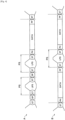
- FIGS. 2 and 3 are explanatory diagrams illustrating formats of packets defined by the MIPI CSI-2 standards.
- FIG. 2 illustrates a format of a short packet defined by the MIPI CSI-2 standards
- FIG. 3 illustrates a format of a long packet defined by the MIPI CSI-2 standards.
- the long packet is data including a packet header ("PH" illustrated in FIG. 3 ), a payload ("Payload Data” illustrated in FIG. 3 ), and a packet footer ("PF" illustrated in FIG. 3 ).
- the short packet is data that has a structure similar to the packet header ("PH" illustrated in FIG. 3 ) as illustrated in FIG. 2 .
- VVC Virtual channel
- VC values are recorded in header portions of both the short packet and the long packet, and arbitrary VC numbers can be applied to each packet. Packets to which the same VC number is applied are handled as packets that belong to the same image data.
- DT data type
- the end of the packet is recorded as the number of words in Word Count in the header portion of the long packet.
- An error correcting code is recorded in ECC in the header portions of the short packet and the long packet.
- a high-speed differential signal is used in a period during which a data signal is transferred, and a low-power signal is used in a blanking period of the data signal.
- the period during which the high-speed differential signal is used is called a high speed state (HPS) period while the period during which the low power signal is used is called a low power state (LPS) period.
- HPS high speed state
- LPS low power state
- FIG. 4 is an explanatory diagram illustrating an example of a signal waveform related to transmission of a packet in accordance with the MIPI CSI-2 standards.
- a in FIG. 4 illustrates an example of transfer of a packet
- B in FIG. 4 illustrates another example of transfer of a packet.
- ST, "ET”, “PH” "PF”, 'SP", and "PS" illustrated in FIG. 4 have the following meanings.
- the image sensor 100 and the processor 200 are electrically connected to each other by a control bus B2 that is different from the data bus B1, for example.
- the control bus B2 is a transfer path for other signals, and connects the image sensor 100 to the processor 200. For example, control information output from the processor 200 is transferred from the processor 200 to the image sensor 100 via the control bus B2.
- the control information includes information for control and processing commands, for example.
- information for control data for controlling functions of the image sensor 100, such as one or two or more of data indicating an image size, data indicating a frame rate, and data indicating the amount of an output delay from reception of an image output command to an image output is exemplified.
- control information may include identification information indicating the image sensor 100.
- identification information arbitrary data with which it is possible to specify the image sensor 100, such as an ID set for the image sensor 100 is exemplified.
- the information transferred from the processor 200 to the image sensor 100 via the control bus B2 is not limited to the example described above.
- the processor 200 may transfer region designation information designating a region in an image via the control bus B2.
- region designation information data in an arbitrary form with which a region can be specified, such as data indicating a position of a pixel included in the region (for example, coordinate data representing a position of a pixel included in the region using coordinates), is exemplified.
- FIG. 1 illustrates an example in which the image sensor 100 and the processor 200 are electrically connected to each other by the control bus B2, the image sensor 100 and the processor 200 may not be connected by the control bus B2.
- the image sensor 100 and the processor 200 may transmit and receive control information and the like through wireless communication of an arbitrary communication scheme.
- the memory 300 is a recording medium that the communication system 1000 has.
- a volatile memory such as a random access memory (RAM) or a nonvolatile memory such as a flash memory is exemplified.
- the memory 300 operates using electrical power supplied from an internal power source (not illustrated) that is included in the communication system 1000, such as a battery, or electrical power supplied from an external power source of the communication system 1000.
- An image output from the image sensor 100 for example, is stored in the memory 300.
- the recording of the image in the memory 300 is controlled by the processor 200, for example.
- the display device 400 is a display device that the communication system 1000 has.
- a liquid crystal display and an organic electro-luminescence display (organic EL display), also known as an organic light emitting diode display (OLED display) are exemplified.
- the display device 400 operates using electrical power supplied from an internal power source (not illustrated) that is included in the communication system 1000, such as a battery, or electrical power supplied from an external power source of the communication system 1000.
- Various images and screens such as an image output from the image sensor 100, a screen related to an application that is executed by the processor 200, and a screen related to a user interface (UI), are displayed on a display screen of the display device 400.
- the display of the image and the like on the display screen of the display device 400 is controlled by the processor 200, for example.
- the processor 200 receives data transmitted from the image sensor 100 and processes the received data. As described above, the processor 200 serves as a reception device in the communication system 1000. An example of a configuration related to processing of data transmitted from the image sensor 100 (a configuration for serving as the reception device) will be described later.
- the processor 200 includes one or two or more processors, various processing circuits, and the like that include arithmetic circuits such as a micro processing unit (MPU), for example.
- the processor 200 operates using electrical power supplied from an internal power source (not illustrated) that is included in the communication system 1000, such as a battery, or electrical power supplied from an external power source of the communication system 1000.
- the processor 200 performs various kinds of processing such as processing related to control of recording of image data in the recording medium such as the memory 300, processing related to control of display of an image on the display screen of the display device 400, and processing of executing arbitrary application software, for example.
- processing related to the control of recording "processing of delivering control data including a recording command and data that is caused to be recorded in the recording medium to the recording medium such as the memory 300" is exemplified.
- processing related to the control of the display "processing of delivering control data including a display command and data that is caused to be displayed on the display screen to the display device such as a display device 400” is exemplified.
- the processor 200 may control functions of the image sensor 100 by transmitting control information to the image sensor 100, for example.
- the processor 200 can also control data to be transmitted from the image sensor 100 by transmitting region designation information to the image sensor 100, for example.
- Image sensor 100 transmission device
- the image sensor 100 has an imaging function and a transmission function and transmits data indicating an image generated by image capturing. As described above, the image sensor 100 serves as a transmission device in the communication system 1000.
- the image sensor 100 includes "an imaging device such as a digital still camera, a digital video camera, or a stereo camera” or an image sensor device of an arbitrary scheme capable of generating an image, such as “an infrared sensor” and "a distance image sensor” and has a function of transmitting the generated image.
- the image generated by the image sensor 100 corresponds to data indicating a sensing result of the image sensor 100.
- An example of a configuration of the image sensor 100 will be described later.
- the image sensor 100 transmits data corresponding to a region set in an image (hereinafter referred to as "region data") according to the transmission method according to the embodiment, which will be described later.
- region data data corresponding to a region set in an image
- the control related to the transmission of the region data is performed by a component (which will be described later) that functions as an image processing unit in the image sensor 100, for example.
- the region set in an image is referred to as a region of interest (ROI) in some cases.
- ROI region of interest
- processing related to the setting of a region in the image arbitrary processing with which it is possible to specify a partial region in the image (or arbitrary processing capable of cutting a partial region from the image) such as "processing of detecting an object in the image and setting a region including the detected object," or "processing of setting a region designated by an operation performed on an arbitrary operation device or the like" is exemplified.
- the processing related to the setting of the region in the image may be performed by the image sensor 100 or may be performed by an external device such as the processor 200.
- the image sensor 100 specifies the region in accordance with a result of the processing related to the setting of the region in the image.
- the image sensor 100 specifies the region on the basis of region designation information acquired from the external device.
- the amount of data related to the transfer becomes smaller than the data amount when the entire image is transferred because the region data, that is, partial data of the image, is transmitted. Accordingly, various advantages achieved by the reduction of the data amount are achieved by the image sensor 100 transmitting the region data, and for example, a transfer time is shortened and a load related to the transfer is reduced in the communication system 1000.
- the image sensor 100 can also transmit data indicating the entire image.
- the image sensor 100 can perform the transmission of the region data and the transmission of the data indicating the entire image in a selectively switched manner.
- the image sensor 100 transmits the region data or transmits the data indicating the entire image depending on a set operation mode, for example.
- the setting of the operation mode is performed by an operation performed on an arbitrary operation device, for example.
- the image sensor 100 may selectively switch between the transmission of the region data and the transmission of the data indicating the entire image on the basis of region designation information acquired from an external device.
- the image sensor 100 transmits the region data of the region corresponding to the region designation information.
- the image sensor 100 transmits data indicating the entire image.
- the communication system 1000 has the configuration illustrated in FIG. 1 , for example. Note that the configuration of the communication system according to the embodiment is not limited to the example illustrated in FIG. 1 .
- the image sensor 100 has been exemplified as the device that serves as the transmission device in FIG. 1
- a device that serves as the transmission device is not limited to the image sensor 100.
- the communication system according to the embodiment has a configuration that has an image sensor device such as an imaging device and a transmitter that is electrically connected to the image sensor device, the transmitter may serve as the transmission device.
- the processor 200 has been exemplified as the device that serves as the reception device in FIG. 1
- the device that serves as the reception device is not limited to the processor 200.
- an arbitrary device that has a function of receiving data can serve as the reception device in the communication system according to the embodiment.
- the communication system according to the embodiment may not have the memory 300 in a case in which the image transmitted from the image sensor 100 is stored in a recording medium outside the communication system, in a case in which the image transmitted from the image sensor 100 is stored in a memory provided in the processor 200, in a case in which the image transmitted from the image sensor 100 is not recorded, or the like.
- the communication system according to the embodiment can employ a configuration in which the communication system does not have the display device 400 illustrated in FIG. 1 .
- the communication system according to the embodiment may have an arbitrary configuration in accordance with functions of an electronic device to which the communication system according to the embodiment is applied as will be described later.
- the embodiment is not limited to such an example.
- the embodiment can be applied to various electronic devices such as a communication device such as a smartphone, a drone (equipment capable of performing operations through remote operations or autonomous operations), a moving body such as a vehicle, a computer such as a personal computer (PC), a tablet-type device, and a game console.
- a communication device such as a smartphone, a drone (equipment capable of performing operations through remote operations or autonomous operations), a moving body such as a vehicle, a computer such as a personal computer (PC), a tablet-type device, and a game console.
- the transmission method according to the embodiment is applied to the image sensor 100 (the transmission device according to the embodiment) illustrated in FIG. 1
- the processing related to the transmission method according to the embodiment is performed by an IC chip (which will be described later) that functions as an image processing unit, for example, in the image sensor 100.
- the processing related to the transmission method according to the embodiment may be performed by another component that functions as an image processing unit in the image sensor 100.
- FIG. 5 san explanatory diagram illustrating an example of regions set in the image.
- FIG. 5 illustrates four regions, namely a region 1, a region 2, a region 3, and a region 4 as an example of the regions. Note that it is needless to say that the region set in the image is not limited to the example illustrated in FIG. 5 .
- the row in the image means that the y coordinates are the same when the positions of the pixels are represented by a two-dimensional plane coordinates (x, y).
- the image sensor 100 sets region information corresponding to the region set in the image for each row in the image.
- the image sensor 100 causes the set region information and the region data corresponding to the region to be transmitted for each row.
- the image sensor 100 causes the region information and the region data for each row to be transmitted in accordance with a predetermined order, such as an ascending order a descending order of the values of the y coordinates, for example.
- the image sensor 100 may cause the region information and the region data for each row to be transmitted in a random order.
- the region information according to the embodiment is data (data group) for specifying, on the side of the reception device, the region set in the image.
- the region information includes, for example, information indicating the position of the row, identification information of the region included in the row, information indicating the position of a column of the region included in the row, and information indicating the size of the region included in the row.
- the information included in the region information can change depending on a transmission scheme, which will be described later.
- one or both of the identification information of the region included in the row and the information indicating the size of the region included in the row may not be included in a second transmission scheme and a third transmission scheme, which will be described later.
- the VC number may serve as the identification information of the region included in the row according to the second transmission scheme and the third transmission scheme, which will be described later.
- the region information includes the information indicating the position of the row, the identification information of the region included in the row, the information indicating the position of the column of the region included in the row, and the information indicating the size of the region included in the row.
- the information indicating the position of a row arbitrary data with which it is possible to specify a row, such as data indicating a number of a y coordinate or data indicating a value of a y coordinate calculated by incrementing an initial value (for example, "0 (zero)" is exemplified.
- the information indicating the position of the row will be referred to as "Y" in some cases.
- identification information of a region arbitrary data with which it is possible to uniquely specify the region, such as data indicating an ID of a region such as a number applied to the region is exemplified.
- the identification information of the region will be referred to as "ROI ID” or "I” in some cases.
- the information indicating the position of a column of the region As the information indicating the position of a column of the region, arbitrary data with which it is possible to specify the column, such as data indicating a number of an x coordinate, is exemplified.
- the information indicating the position of the column in the region will be referred to as "ROI X" or "X" in some cases.
- the reception device that has received the region information by the information indicating the position of the row, the identification information of the region, the information indicating the position of the column of the region, and the information indicating the size of the region being set in the region information as described above, for example, can perform specification of the region, specification of the position of the region, and specification of the ROI length. In addition, it is possible to uniquely specify at which position and with which ROI length the region has been set in the row by the specification of the region, the specification of the position of the region, and the specification of the RIO length being performed.
- the communication system 1000 can be respectively compatible with the transfer of "region data in the rectangular region, such as the region 1 in FIG. 5 " and "region data in regions with arbitrary shapes other than the rectangular shape, such as the region 2, the region 3, and the region 4 in FIG. 5 " by the information indicating the position of the row, the identification information of the region, the information indicating the position of the column of the region, and the information indicating the size of the region being set in the region information.
- the image sensor 100 may collectively set, in the region information, the information to be included in the region information for each region included in the row.
- the image sensor 100 collectively sets, in the region information, the identification information of the region, the information indicating the position of the column of the region, and the information indicating the size of the region, for example, for each region included in the row.
- the collective setting of the region information for each region means setting of the identification information of the region, the information indicating the position of the column of the region, and the information indicating the size of the region, for example (an example of the information included in the region information) as a group of data in the region information.
- the image sensor 100 sets the region information for each row, the position of the row is constant even if a plurality of regions are included. Therefore, the image sensor 100 sets one piece of information indicating the position of the row in the region information. Note that it is needless to say that the image sensor 100 can collectively set the information indicating the position of the row, the identification information of the region, the information indicating the position of the column of the region, and the information indicating the size of the region for each region included in the row.
- the reception device that has received the region information can more easily perform the specification of the region, the specification of the position of the region, and the specification of the ROI length for each region by the identification information of the region, the information indicating the position of the column of the region, and the information indicating the size of the region being collectively set for each region included in the row as described above.
- the communication system 1000 can address "the transfer of the region data in the case in which a plurality of regions are set in in one row, such as the region 1 and the region 2 in FIG. 5 " and "the transfer of the region data in the case in which the set regions are overlaid, such as the region 3 and the region 4 in FIG. 5 " by the identification information of the region, the information indicating the position of the column of the region, and the information indicating the size of the region being collectively set for each region included in the row.
- a plurality of same regions can be present in one row depending on a set region, as illustrated as the region 2 in FIG. 5 , for example.
- the image sensor 100 may set the region information corresponding to the number of the same regions.
- the image sensor 100 sets the identification information of the region, the information indicting the position of the column of the region, and the information indicating the size of the region corresponding to the number of the present regions, for example, in the region information.
- the reception device that has received the region information can perform the specification of the region, the specification of the position of the region, and the specification of the ROI length for each of the plurality of same regions by the identification information of the region, the information indicating the position of the column of the region, and the information indicating the size of the region corresponding to the number of the same regions that are present in one row being set in the region information, for example.
- the communication system 1000 can address the transfer of the region data in the region 2 in FIG. 5 by the region information corresponding to the number of the plurality of same regions that are present in one row being set in the region information.
- the reception device that has received the region information can uniquely specify the region set in the row by the region information that includes various kinds of information as described above, for example, being set for each row.
- the information included in the region information is not limited to the example described above.
- the region information may include other data such as data indicating the number of regions included in the row (hereinafter, referred to as "Num of ROI" in some cases) and the like. Specific examples of the information included in the region information will be described later.
- processing related to the transmission method according to the embodiment is not limited to the above basic processing.
- the image sensor 100 may not set, in the region information, information that does not change from the information included in the region information in a row that is caused to be transmitted immediately before, in the information included in the region information. That is, the image sensor 100 causes the region information, which includes information that has changed from the row from which the region information is caused to be transmitted immediately before, to be transmitted.
- the data amount of the region information is possible to cause the data amount of the region information to be further reduced by the information, which has not changed from the information included in the region information in the row to be caused to be transmitted immediately before, being not transmitted as described above.
- the reduction of the data amount of the region information contributes to shortening of a transfer time and reduction of a load related to the transfer in the communication system 1000.
- the image sensor 100 sets the identification information of the region in the region information when the information indicating the position of the column of the region is set in the region information.
- the image sensor 100 sets the identification information of the region in the region information when the information indicating the size of the region is set in the region information. That is, the image sensor 100 sets the identification information of the region in the region information in a case in which one or both the x coordinate and the ROI length of the region are changed from the content included in the region information in the row that is caused to be transmitted immediately before.
- the reception device that has received the region information can uniquely specify the region corresponding to the content of the change by the image sensor 100 setting the identification information of the region in the region information in a case in which one of or both the x coordinate and the ROI length of the region are changed.
- the image sensor 100 can cause the region information and the region data for each row to be transmitted in a predetermined order.
- the image sensor 100 may not set the information indicating the position of the row in the region information.
- the reception device can specify in which row the received region information and region data are included, by following the predetermined order even in a case in which the image sensor 100 does not set the information indicating the position of the row in the region information.
- the image sensor 100 transmits the region information and the region data for each row by performing the basis processing described in "above ⁇ 3-1>” or “the basis processing described in "above ⁇ 3-1> and the exception processing described in above ⁇ 3-2>". Next, the transmission scheme in which the region information and the region data are transmitted will be described.
- the image sensor 100 stores the region information and the region data in a payload of a packet and causes the region information and the region data to be transmitted for each row.
- FIG. 6 is an explanatory diagram illustrating an example of data that is transmitted in a first transmission scheme related to the transmission method according to the claimed invention.
- FIG. 6 illustrates "an example in which the region information and the region data respectively corresponding to the region 1, the region 2, the region 3, and the region 4 illustrated in FIG. 5 are stored in a payload of a long packet of MIPI illustrated in FIG. 3 and are transmitted for each row".
- FS illustrated in FIG, 6 represents a frame start (FS) packet in accordance with the MIPI CSI-2 standard
- FE frame end
- Embedded Data illustrated in FIG. 6 is data that can be embedded in a header or a footer of the data to be transmitted. As “Embedded Data”, additional information that is additionally transmitted by the image sensor 100 is exemplified. Hereinafter, Embedded Data will be referred to as "EBD" in some cases.
- the additional information one or two or more of information indicating the data amount of the region, information indicating the size of the region, and information indicating priority of the region are exemplified.
- the information indicating the data amount of the region data in an arbitrary form with which it is possible to specify the data amount of the region such as "the number of pixels included in the region (or the data amount of the region) and data indicating the data amount of the header" is exemplified.
- the reception device can specify the data amount of each region by the information indicating the data amount of the region being transmitted as "Embedded Data” illustrated in FIG. 6 . That is, it is possible to cause the reception device to specify the data amount of the region even in a case in which the reception device does not have a function of calculating the data amount of each region on the basis of the region information, by the information indicating the data amount of the region being transmitted as "Embedded Data” illustrated in FIG. 6 .
- the information indicating the size of the region data in an arbitrary form with which it is possible to specify the size of the region, such as "the data indicating the rectangular region including the region (for example, data indicating the number of pixels in the horizontal direction and the number of pixels in the vertical direction in the rectangular region) is exemplified.
- the information indicating priority of regions is data used in processing of region data, for example.
- the priority indicated by the information indicating priority of regions is utilized for an order in which the regions are processed, in processing performed in a case in which the set regions are overlaid such as the region 3 and the region 4 in FIG. 5 , and the like.
- the additional information according to the embodiment is not limited to the example described above.
- various kinds of data such as exposure information indicating an exposure value or the like of the image sensor device and gain information indicating a gain of the image sensor device are exemplified.
- Each of the exposure value indicated by the exposure information and the gain indicated by the gain information is set in the image sensor device under control performed by the processor 200 via the control bus B2.
- FIG. 7 is an explanatory diagram for describing an example of Embedded Data transmitted according to the first transmission scheme related to the transmission method according to the embodiment.
- FIG. 7 illustrates an example in which the information indicating the size of the region is transmitted as "Embedded Data" illustrated in FIG. 6 " and the transmitted information indicating the size of the region is data indicating a minimum rectangular region including the region.
- FIG. 7 illustrates an example in which four regions, namely the region 1, the region 2, the region 3, and the region 4 have been set similarly to FIG. 5 .
- the reception device can specify the minimum rectangular region including the region 1 illustrated as R1 in FIG. 7 , the minimum rectangular region including the region 2 illustrated as R2 in FIG. 7 , the minimum rectangular region including the region 3 illustrated as R3 in FIG. 7 , and the minimum rectangular region including the region 4 illustrated as R4 in FIG. 7 by the information indicating the size of the region being transmitted as "Embedded Data" illustrated in FIG. 6 . That is, it is possible to cause the reception device to specify the minimum rectangular region including each region on the basis of the region information even in the case in which the reception device does not have a function of specifying the minimum rectangular region including each region on the basis of the region information, by the information indicating the size of the region being transmitted as "Embedded Data" illustrated in FIG. 6 . Note that it is needless to say that the information indicating the size of the region is not limited to the data indicating the minimum rectangular region including each region.
- the reception device can specify the processing order of the regions or which region is to be processed with priority, for example, by the information indicating the priority of the regions being transmitted as "Embedded Data" illustrated in FIG. 6 . That is, it is possible to control the processing performed by the reception device on the regions by the information indicating the priority of the regions being transmitted as "Embedded Data” illustrated in FIG. 6 .
- "PH” illustrated in FIG. 6 is a packet header of a long packet.
- the packet header of the long packet related to the first transmission scheme may also function as data (change information) indicating whether or not the information included in the region information has changed from the region information included in a packet that is caused to be transmitted immediately before. That is, it is possible to state that "PH” illustrated in FIG. 6 is data indicating a data type of the long packet.
- the image sensor 100 sets "0x38" in "PH” in a case in which the information included in the region information has changed from the region information included in the packet that is caused to be transmitted immediately before. In this case, the image sensor 100 stores the region information in the payload of the long packet.
- the image sensor 100 sets "0x39" in "PH” in a case in which the information included in the region information has not changed from the region information included in the packet that is caused to be transmitted immediately before. In this case, the image sensor 100 does not store the region information in the payload of the long packet. That is, in the case in which the information included in the region information has not changed from the region information included in the packet that is caused to be transmitted immediately before, the image sensor 100 does not transmit the region information.
- Information illustrated in FIG. 6 is region information stored in the payload (the same applies to the other diagrams). As illustrated in FIG. 6 , the region information is stored in the head portion of the payload. Hereinafter, region information will be referred to as "ROI Info" in some cases.
- Each of "1", “2", “3”, and “4" illustrated in FIG. 6 corresponds to the region data of the region 1, the region data of the region 2, the region data of the region 3, and the region data of the region 4 that are stored in the payload (the same applies to the other drawings). Note that although the respective pieces of region data are illustrated in a divided manner in FIG. 6 , this represents the division for convenience, and there is no division in the data to be stored in the payload (the same applies to the other drawings).
- the region data will be referred to as "ROI DATA" in some cases.
- FIG. 8 is an explanatory diagram illustrating an example of a configuration of a long packet transmitted according to the first transmission scheme related to the transmission method according to the embodiment.
- ROI Info Type illustrated in FIG. 8 is data indicating a transfer scheme of "ROI Info Parameter".
- the reception device that has received the region information can uniquely specify the content of "ROI Ingo Parameter” by "ROI Info Type” being set.
- ROI Info Type corresponds to other data indicating a data type of the long packet. That is, for the long packet related to the first transmission scheme, two items, namely "PH" and "ROI Info Type” are defined as data types of the long packet.
- ROI Info Type is 1-byte data, for example, and has the following meaning when represented by Verilog-HDL description. Note that it is needless to say that "ROI Info Type” is not limited to 1-byte data.
- the region information related to the first transmission scheme may include a flag (hereinafter, referred as "NO CHANGE flag") indicating that both the x coordinate and the ROI length of the region have not changed from the region information included in the packet that is caused to be transmitted immediately before, for example.
- NO CHANGE flag indicates that there has been no change (for example, in a case in which the NO CHANGE flag is 1'b1)
- [1] and [0] described above of "ROI Info Type" may be omitted.
- NO CHANGE flag a most significant bit (MSB) of the ROI ID is exemplified. Note that the NO CHANGE flag may be data that is separate from the ROI ID.
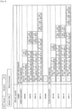
- FIG. 9 is an explanatory diagram illustrating an example of data transmitted according to the first transmission scheme related to the transmission method according to the embodiment and is a diagram specifically illustrating the data illustrated in FIG. 6 in accordance with the configuration of the long packet illustrated in FIG. 8 .
- the region information and the region data corresponding to each of the region 1, the region 2, the region 3, and the region 4 illustrated in FIG. 5 are stored in the payload of the long packet of MIPI as illustrated in FIG. 9 , for example, and are transmitted for each row.
- the image sensor 100 can transmit, as Embedded Data" illustrated in FIG. 6 , one or two or more of the information indicating the data amount of the region, the information indicating the size of the region, and the information indicating the priority of the region (one example of the additional information).
- the first transmission scheme related to the transmission method according to the embodiment has features described below, for example. Note that it is needless to say that the features that the first transmission scheme related to the transmission method according to the embodiment has are not limited to the examples described below.
- the region information that is stored in the head portion of the payload and is then transmitted has the features as described below, for example, in the first transmission scheme. Note that it is needless to say that the features that the region information related to the first transmission scheme has are not limited to the examples described below.
- the first transmission scheme has the advantages described below, for example.
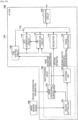
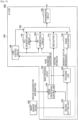
- FIG. 10 is a hardware block diagram illustrating an example of a configuration of the image sensor 100 that is compatible with the first transmission scheme related to the transmission method according to the embodiment.
- the image sensor 100 includes an image sensor device 102 and an IC chip 104, for example.
- the image sensor 100 illustrated in FIG. 10 operates using electrical power supplied from an internal power source (not illustrated) that is included in the communication system 1000, such as a battery, or electrical power supplied from an external power source of the communication system 1000.
- the image sensor device 102 is "an imaging device such as a digital still camera” or an image sensor device of an arbitrary scheme capable of generating an image, such as an "infrared sensor” or a “distance image sensor”.
- the imaging device that functions as the image sensor device 102 includes lens/imaging elements and a signal processing circuit.
- the lens/imaging elements include for example, an optical system lens and an image sensor using a plurality of imaging elements such as complementary metal oxide semiconductors (CMOSs) or charge coupled devices (CCDs).
- CMOSs complementary metal oxide semiconductors
- CCDs charge coupled devices
- the signal processing circuit includes an automatic gain control (AGC) circuit or an analog to digital converter (ADC), for example, and converts an analog signal generated by the imaging elements into a digital signal (image data).
- AGC automatic gain control
- ADC analog to digital converter
- the signal processing circuit performs various kinds of processing related to RAW development, for example.
- the signal processing circuit may perform various kinds of signal processing such as white balance correction processing, color tone correction processing, gamma correction processing, YCbCr conversion processing, and edge emphasis processing, for example.
- the signal processing circuit may perform processing related to setting of a region in the image and deliver the region designation information to the IC chip 104. Further, the signal processing circuit may deliver a variety of kinds of data such as exposure information and gain information to the IC chip 104.
- the signal indicating the image generated by the image sensor device 102 is delivered to the IC chip 104.
- the IC chip 104 converts the analog signal to a digital signal by using an ADC provided therein and processes the image data obtained by the conversion, for example.
- image data is delivered from the image sensor device 102 to the IC chip 104 will be described as an example.
- the IC chip 104 is an integrated circuit (IC) with a circuit related to a function of transmitting data according to the first transmission scheme formed into a chip shape, processes the image data delivered from the image sensor device 102, and transmits data corresponding to the generated image.
- the data corresponding to the image is image data (that is, data indicating the entire image) delivered from the image sensor device 102 or region information and region data.
- the circuit related to the function of transmitting data according to the first transmission scheme is not limited to implementation in the form of one IC chip and may be formed of a plurality of IC chips.
- the IC chip 104 includes, for example, an image processing circuit 106, a LINK control circuit 108, an ECC generation circuit 110, a PH generation circuit 112, an EBD buffer 114, an image data buffer 116, a synthesis circuit 118, and a transmission circuit 120.
- the image processing circuit 106 is a circuit that has a function of performing processing related to the transmission method according to the embodiment.
- the image processing circuit 106 sets region information for each row in the image, and causes the LINK control circuit 108, the ECC generation circuit 110, the PH generation circuit 112, the EBD buffer 114, the image data buffer 116, the synthesis circuit 118, and the transmission circuit 120 to transmit the set region information and the region data corresponding to the region according to the first transmission scheme.
- the image processing circuit 106 also can cause the image data delivered from the image sensor device 102 (that is, data indicating the entire image) to be transmitted for each row.
- a processor such as an MPU is exemplified.
- the image processing circuit 106 has a region cutting unit 122, an image processing control unit 124, and an encoding unit 126, for example.
- the region cutting unit 122 plays a role in performing processing related to setting of a region in the image and sets the region (ROI) in the image indicated by the image data delivered from the image sensor device 102.
- the region cutting unit 122 performs processing related to setting of the region in the image in accordance with a set operation mode, for example.
- the operation mode is an operation mode in which the region data is transmitted
- the region cutting unit 122 performs the processing related to the setting of the region in the image.
- the region cutting unit 122 does not perform the processing related to the setting of the region in the image.
- the region cutting unit 122 detects an object by performing arbitrary object detection processing on the image, for example, and sets a region including the detected object for each detected object.
- the region cutting unit 122 may set a region designated through an operation performed on an arbitrary operation device or the like.
- a rectangular region as illustrated as the region 1 in FIG. 5 and regions with arbitrary shapes other than the rectangular shape set in the image, such as the region 2, the region 3, and the region 4 in FIG. 5 can be included.
- the region cutting unit 122 delivers the region designation information indicating the set region to the image processing control unit 124, for example. In addition, in a case in which the region has not been set, the region cutting unit 122 does not deliver the region designation information to the image processing control unit 124.
- the region cutting unit 122 delivers the image data, which has been delivered from the image sensor device 102, to the encoding unit 126.
- the image processing control unit 124 plays a role in performing the processing related to the transmission method according to the embodiment, sets the region information for each row in the image, and delivers the set region information to the encoding unit 126 and the PH generation circuit 112.
- the image processing control unit 124 specifies the region included in each row in the image on the basis of the region designation information acquired from the region cutting unit 122 and the region designation information (not illustrated) acquired form an external device, for example. Then, the image processing control unit 124 sets the region information for each row on the basis of the specified region. At this time, the image processing control unit 124 may not set the information, which has not changed from the information included in the region information in the row that is caused to be transmitted immediately before, in the region information as described above as the exception processing.
- the image processing control unit 124 does not set the region information.
- processing performed by the image processing control unit 124 is not limited to the examples described above.
- the image processing control unit 124 may generate frame information, for example, and deliver the generated frame information to the LINK control circuit 108.
- the frame information a VC number applied to each frame is exemplified.
- the frame information may include data indicating a data type such as YUV data, RGB data, or RAW data.
- the image processing control unit 124 may perform processing of setting the additional information and deliver the set additional information to the EBD buffer 114.
- processing of generating the additional information is exemplified.
- processing of generating the additional information one or two or more of processing of generating information indicating the data amount of the region, processing of generating information indicating the size of the region, and processing of generating information indicating priority of the region are exemplified.
- the processing of setting the additional information is not limited to the processing of generating the additional information.
- the image processing control unit 124 may set, as the additional information, information acquired from the image sensor device 102 such as the exposure information and the gain information.
- the image processing control unit 124 may set, as the additional information, a variety of data items related to the region, such as data indicating a physical region length, data indicating an output region length, data indicating an image format, and data indicating the total data amount, for example.
- the physical region length the number of pixels of the image sensor device 102 is exemplified.
- the output region length the number of pixels (the length on the image) of the image output from the image sensor device 102 is exemplified.
- the encoding unit 126 encodes the image data delivered from the image sensor device 102 in a predetermined scheme such as a scheme that is compatible with Joint Photographic Experts Group (JPEG), for example.
- JPEG Joint Photographic Experts Group
- the encoding unit 126 delivers the encoded image data to the image data buffer 116.
- the encoded image data that is, the data indicating the entire encoded image will be referred to as "ordinary data" in some cases.
- the encoding unit 126 delivers the acquired region information and the encoded region data corresponding to the region to the image data buffer 116.
- the image processing circuit 106 performs processing related to the transmission method according to the embodiment by having the region cutting unit 122, the image processing control unit 124, and the encoding unit 126. Note that the functional blocks of the image processing circuit 106 illustrated in FIG. 10 are obtained by dividing the functions that the image processing circuit 106 has for convenience, and the dividing of the functions of the image processing circuit 106 is not limited to the example illustrated in FIG. 10 .
- the LINK control circuit 108 delivers the frame information to the ECC generation circuit 110, the PH generation circuit 112, and the synthesis circuit 118 for each row, for example.
- the ECC generation circuit 110 sets an error correction code for each row.
- the ECC generation circuit 110 generates an error correction code of one row in the frame information (for example, the VC number. the data type, or the like) on the basis of data of the row.
- the ECC generation circuit 110 delivers the generated error correction code to the PH generation circuit 112 and the synthesis circuit 118, for example.
- the ECC generation circuit 110 may generate the error correction code in conjunction with the PH generation circuit 112.
- the PH generation circuit 112 generates a packet header for each row by using the frame information.
- the PH generation circuit 112 may generate the packet header on the basis of the region information delivered from the image processing circuit 106 (the image processing control unit 124 in the example in FIG. 10 ). Specifically, the PH generation circuit 112 sets "the data indicating whether or not the information included in the region information has changed from the region information included in the packet that is caused to be transmitted immediately before" (change information) as described above in the packet header on the basis of the region information.
- the EBD buffer 114 is a buffer that temporarily holds the additional information delivered from the image processing circuit 106 (the image processing control unit 124 in the example in FIG. 10 ).
- the EBD buffer 114 outputs the additional information as "Embedded Data" to the synthesis circuit 118 at a predetermined timing. Note that "Embedded Data" output from the EBD buffer 114 may be delivered to the synthesis circuit 118 via the image data buffer 116, which will be described later.
- the image data buffer 116 is a buffer that temporarily hold data (the ordinary data or the region information and the region data) delivered from the image processing circuit 106 (the encoding unit 126 in the example in FIG. 10 ).
- the image data buffer 116 outputs the held data to the synthesis circuit 118 for each row at a predetermined timing.
- the synthesis circuit 118 generates a packet to be transferred on the basis of data respectively acquired from the ECC generation circuit 110, the PH generation circuit 112, the EBD buffer 114, and the image data buffer 116, for example.
- the transmission circuit 120 transmits the packet delivered from the synthesis circuit 118 via the data bus B1 for each row (an example of a signal transfer path; the same applies to the following description). For example, the transmission circuit 120 transmits the packet by a high-speed differential signal as illustrated in FIG. 4 .
- the transmission circuit 120 transmits the set region information and the region data corresponding to the region in a long packet for each row as illustrated in FIG. 9 .
- the transmission circuit 120 transmits the long packet in which the data corresponding to each row is stored in the payload, for each row. Note that the transmission circuit 120 can transmit the additional information as "Embedded Data" even in this case.
- the image sensor 100 corresponding to the first transmission scheme has a hardware configuration illustrated in FIG. 10 , for example. Note that it is needless to say that the hardware configuration of the image sensor 100 corresponding to the first transmission scheme is not limited to the example illustrated in FIG. 10 .
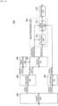
- FIG. 11 is a functional block diagram illustrating an example of a configuration of the processor 200 that is compatible with the first transmission scheme related to the transmission method according to the embodiment.
- the processor 200 has a header separation unit 202, a header interpretation unit 204, a payload separation unit 206, an image processing unit 208, and a transmission unit 210, for example.
- the header separation unit 202 separates header data corresponding to the header portion and payload data corresponding to the payload portion from the received data.
- the header separation unit 202 separates the header data from the received data in accordance with a rule defined in advance by standards or the like, for example.
- the header separation unit 202 may separate the payload data from the received data in accordance with the rule defined in advance by standards or the like or may separate the payload data from the received data on the basis of a result of processing performed by the header interpretation unit 204, for example.
- the header interpretation unit 204 interprets content indicated by the header data.
- the header interpretation unit 204 interprets that the information included in the region information has changed from the region information included in the packet that is caused to be transmitted immediately before in a case in which the header data indicates "0x38", for example. In addition, the header interpretation unit 204 may interpret that the region information is included in the payload data in this case.
- the header interpretation unit 204 interprets that the information included in the region information has not changed from the region information included in the packet that is caused to be transmitted immediately before in a case in which the header data indicates "0x39", for example. In addition, the header interpretation unit 204 may interpret that the region information is not included in the payload data in this case.
- the header interpretation unit 204 may specify the position of the payload data and deliver the specified position to the header separation unit 202.
- the header interpretation unit 204 can also interpret whether or not the payload data is "Embedded Data".
- the payload separation unit 206 separates the additional information, the region information, and the image data (the ordinary data or the region data; the same applies to the description of FIG. 11 below) from the payload data on the basis of the result of the interpretation performed by the header interpretation unit 204
- the payload separation unit 206 regards the payload data as the additional information.
- the payload separation unit 206 separates the region information and the image data from the payload data.
- the region information and the region data are stored in the payload while the region information is stored in the head portion of the payload.
- the region information is not stored in the payload. Accordingly, the payload separation unit 206 can separate the region information and the image data by processing the payload from the head portion.
- the image processing unit 208 processes the image data for each row on the basis of the additional information, the region information, and the image data delivered from the payload separation unit 206 and obtains data indicating the image corresponding to the region or the data indicating the entire image.
- the image processing unit 208 may determine whether or not the data acquired via the data bus B1 is data indicating the image corresponding to the region or data indicating the entire image on the basis of the information delivered from the payload separation unit 206, for example, and perform processing in a processing mode in accordance with the result of the determination.
- the image processing unit 208 determines that the data acquired via the data bus B1 is data indicating the image corresponding to the region. Then, the image processing unit 208 proceeds to the processing mode in which the region data is processed and obtains data indicating the image corresponding to the region on the basis of the region information and the region data for each row.
- the image processing unit 208 determines that the data acquired via the data bus B1 is data indicating the entire image. Then, the image processing unit 208 proceeds to the ordinary processing mode (the processing mode in which the ordinary data is processed) and obtains the data indicating the entire image on the basis of the ordinary data for each row.
- the ordinary processing mode the processing mode in which the ordinary data is processed
- the method of determining the data acquired via the data bus B1 is not limited to the example described above.
- the image processing unit 208 may determine that the data acquired via the data bus B1 is data indicating the image corresponding to the region in a case in which the information related to the region (for example, one or two or more of the information indicating the data amount of the region, the information indicating the size of the region, and the information indicating priority of the region).
- the image processing unit 208 has a decoding unit 212 and an image generation unit 214, for example.
- the decoding unit 212 decodes the image data by a predetermined scheme corresponding to the encoding performed by the image sensor 100, for example. At this time, the decoding unit 212 may change content of the processing on the basis of the additional information.
- the image generation unit 214 generates the data indicating the image corresponding to the region or the data indicating the entire image from the image data for each row decoded by the decoding unit 212 on the basis of the region information.
- the image generation unit 214 determines that the image data delivered from the decoding unit 212 is region data. Then, in a case in which it is determined that the image data is the region data, the image generation unit 214 divides the region data for each row into the data for each region on the basis of the region information.
- the region information that the image generation unit 214 uses for the processing can include the region information corresponding to the row as a target of the processing and region information corresponding to a row for which the processing has already been performed.
- the image generation unit 214 can uniquely specify the region data included in each row. Accordingly, the image generation unit 214 can generate the data indicating the image corresponding to the region set in the image of a certain frame, for each region.
- the image generation unit 214 determines that the delivered image data is ordinary data. In a case in which the image data is determined to be ordinary data, the image generation unit 214 generates data indicating the entire image from the image data for each row delivered from the decoding unit 212.
- the image processing unit 208 obtains the data indicating the image corresponding to the region or the data indicating the entire image by being provided with the decoding unit 212 and the image generation unit 214, for example.
- the processing performed by the image processing unit 208 is not limited to the example described above.
- the image processing unit 208 can perform a variety of kinds of processing such as processing related to control of recording of image data in a recording medium such as the memory 300, processing related to control of display of an image on a display screen of the display device 400, and processing related to setting of a region in an image, for example, as described above.
- the transmission unit 210 transmits various kinds of data (for example, image data, control information, and the like) to an external device via the control bus B2, various signal lines, and the like.
- data for example, image data, control information, and the like
- the transmission unit 210 communication devices that are provided in the processor 200 and follow predetermined standards such as inter-integrated circuits (I2C) or improved inter-integrated circuits (I3C) are exemplified.
- the communication performed by the transmission unit 210 is controlled by the image processing unit 208, for example.
- the recording of the image data in the recording medium such as the memory 300, the display of the image on the display screen of the display device 400, and the transmission of the region designation information indicating the set region o the image sensor 100 are realized by the image processing unit 208 causing the transmission unit 210 to transmit the various kinds of data (for example, the image data, the control information, and the like).
- the processor 200 can obtain the data indicating the image corresponding to the region or the data indicating the entire image on the basis of the data received from the image sensor 100 by being provided with the header separation unit 202, the header interpretation unit 204, the payload separation unit 206, the image processing unit 208, and the transmission unit 210, for example.
- the functional blocks of the processor 200 illustrated in FIG. 11 is obtained by dividing the functions that the processor 200 has for convenience, and how to divide the functions of the processor 200 is not limited to the example illustrated in FIG. 11 .
- the processor 200 may not have the transmission unit 210.
- the image sensor 100 stores the region data in a payload of a first packet and stores each piece of information included in the region information in a second packet that is different from the first packet. Then, the image sensor 100 causes the first packet and the second packet to be transmitted for each row.
- a long packet of MIPI is exemplified as the first packet related to the second transmission scheme while a short packet of MIPI is exemplified as the second packet related to the second transmission scheme.
- the examples of the first packet and the second packet according to the embodiment are not limited to the examples described above. Other examples of the first packet and the second packet according to the embodiment will be described as a third transmission scheme, which will be described later.
- the case in which the first packet is a long packet of MIPI and the second packet is a short packet of MIPI will be exemplified for the second transmission scheme described below.
- FIG. 12 is an explanatory diagram illustrating an example of data transmitted according to the second transmission scheme related to the transmission method according to the embodiment.
- FIG. 12 illustrates "an example in which each piece of information included in the region information corresponding to the region 1, the region 2, the region 3, and the region 4 illustrated in FIG. 5 is transmitted for each row by a short packet of MIPI illustrated in FIG. 2 ".
- FIG. 12 illustrates "an example in which the region data corresponding to each of the region 1, the region 2, the region 3, and the region 4 illustrated in FIG. 5 is stored in a payload of a long packet of MIPI illustrated in FIG. 3 and is transmitted for each row".
- FIG. 12 illustrates a short packet in which the information indicating the position of the row is stored.
- "I1”, “I2”, “I3”, and “I4" illustrated in FIG. 12 illustrate short packets in which the identification information of the regions corresponding to the region 1, the region 2, the region 3, and the region 4 illustrated in FIG. 5 are respectively stored.
- "X1”, “X2”, “X3”, and “X4" illustrated in FIG. 12 illustrate short packets in which the information indicating the sizes of the regions corresponding to the region 1, the region 2, the region 3, and the region 4 illustrated in FIG. 5 are respectively stored.
- "L1", “L2", “L3”, and “l4" illustrated in FIG. 12 represent short packets in which information indicating the sizes of the regions respectively corresponding to the region 1, the region 2, the region 3, and the region 4 illustrated in FIG. 5 is stored.
- the region information and the region data are stored in a payload of one packet, such as a long packet of MIPI, for example, and are transmitted for each row.
- the region information and the region data are stored separately in different packets and are transmitted for each row.
- the image sensor 100 can transmit, as "Embedded Data" illustrated in FIG. 12 , one or two or more (an example of the additional information) of the information indicating the data amount of the region, the information indicating the size of the region, and the information indicating priority of the region.
- the second transmission scheme related to the transmission method according to the embodiment has the features described below, for example. Note that it is needless to say that the features that the second transmission scheme related to the transmission method according to the embodiment has are not limited to the examples described below.
- the region information transmitted by the short packet has features described below, for example, in the second transmission scheme. Note that it is needless to say that the features that the region information related to the second transmission scheme has are not limited to the examples described below.
- the second transmission scheme has advantages described below, for example.
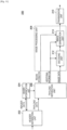
- FIG. 13 is a hardware block diagram illustrating an example of a configuration of the image sensor 100 that is compatible with the second transmission scheme related to the transmission method according to the embodiment.
- the image sensor 100 includes an image sensor device 102 and an IC chip 150, for example.
- the image sensor 100 illustrated in FIG. 13 operates using electrical power or the like supplied from an internal power source (not illustrated) that is included in the communication system 1000 similarly to the image sensor 100 illustrated in FIG. 10 .
- the image sensor device 102 illustrated in FIG. 13 has a function and a configuration that are similar to those of the image sensor device 102 illustrated in FIG. 10 .
- the IC chip 150 is obtained by forming an IC, on which circuits related to the function of transmitting data according to the second transmission scheme are integrated, into a chip shape, processes the image data delivered from the image sensor device 102, and transmits data corresponding to the generated image.
- the circuits related to the function of transmitting data according to the second transmission scheme is not limited to implementation in the form of one IC chip and may be formed of a plurality of IC chips.
- the IC chip 150 includes an image processing circuit 152, a LINK control circuit 108, an ECC generation circuit 110, a PH generation circuit 154, an EBD buffer 114, an image data buffer 116, a synthesis circuit 156, and a transmission circuit 120, for example.
- the link control circuit 108, the ECC generation circuit 110, the EBD buffer 114, the image data buffer 116, and the transmission circuit 120 illustrated in FIG. 13 have functions and configurations that are similar to those of the LINK control circuit 108, the ECC generation circuit 110, the EBD buffer 114, the image data buffer 116, and the transmission circuit 120 illustrated in FIG. 10 , respectively.
- the image processing circuit 152 is a circuit that has a function of performing the processing related to the transmission method according to the embodiment. In a case in which the processing related to the transmission method according to the embodiment is performed, the image processing circuit 152 sets the region information for each row in the image and causes the LINK control circuit 108, the ECC generation circuit 110, the PH generation circuit 154, the EBD buffer 114, the image data buffer 116, the synthesis circuit 156, and the transmission circuit 120 to transmit the set region information and the region data corresponding to the region for each row according to the second transmission scheme. In addition, the image processing circuit 152 can also cause the image data delivered from the image sensor device 102 (that is, data indicating the entire image) to be transmitted for each row.
- a processor such as an MPU is exemplified.
- the image processing circuit 152 has a region cutting unit 122, an image processing control unit 124, and an encoding unit 158, for example.
- the functions of the region cutting unit 122 and the image processing control unit 124 illustrated in FIG. 13 are similar to those of the region cutting unit 122 and the image processing control unit 124 illustrated in FIG. 10 .
- the encoding unit 158 encodes the image data delivered from the image sensor device 102 by a predetermined scheme similarly to the encoding unit 126 illustrated in FIG. 10 .
- the encoding unit 158 delivers the encoded image data to the image data buffer 116 similarly to the encoding unit 126 illustrated in FIG. 10 .
- the encoding unit 158 specifies the region on the basis of the acquired region information and delivers the encoded region data corresponding to the specified region to the image data buffer 116.
- the image processing circuit 152 performs the processing related to the transmission method according to the embodiment by being provided with the region cutting unit 122, the image processing control unit 124, and the encoding unit 158. Note that the functional blocks of the image processing circuit 152 illustrated in FIG. 13 are obtained by dividing the functions that the image processing circuit 152 has for convenience, and how to divide the functions of the image processing circuit 152 is not limited to the example illustrated in FIG. 13 .
- the PH generation circuit 154 generates a short packet in which each piece of information included in the region information is stored, on the basis of the region information delivered from the image processing circuit 152 (the image processing control unit 124 in the example in FIG. 13 ).
- the PH generation circuit 154 generates a packet header of a long packet for each row by using frame information similarly to the PH generation circuit 112 illustrated in FIG. 10 .
- the synthesis circuit 156 generates, as a packet to be transferred, "a short packet in which the region information is stored" and "a long packet in which the image data (the ordinary data or the region data) or each row is stored in the payload" on the basis of the data acquired from each of the ECC generation circuit 110, the PH generation circuit 154, the EBD buffer 114, and the image data buffer 116.
- the transmission circuit 120 transmits the packet delivered from the synthesis circuit 156 via the data bus B1 for each row.
- the transmission circuit 120 stores each piece of information included in the region information in a short packet, stores the region data in the payload of the long packet, and causes the information and the data to be transmitted for each row as illustrated in FIG. 12 .
- the transmission circuit 120 transmits the long packet in which the data corresponding to each row is stored in the payload, for each row similarly to the transmission circuit 120 illustrated in FIG. 10 .
- the transmission circuit 120 can transmit the additional information as "Embedded Data" similarly to the transmission circuit 120 illustrated in FIG. 10 .
- the image sensor 100 that is compatible with the second transmission scheme has a hardware configuration illustrated in FIG. 13 , for example. Note that it is needless to say that the hardware configuration of the image sensor 100 that is compatible with the second transmission scheme is not limited to the example illustrated in FIG. 13 .
- FIG. 14 is a functional block diagram illustrating an example of a configuration of the processor 200 that is compatible with the second transmission scheme related to the transmission method according to the embodiment.
- the processor 200 has a packet separation unit 250, a short packet interpretation unit 252, a long packet interpretation unit 254, a header interpretation unit 256, a payload interpretation unit 258, an image processing unit 208, and a transmission unit 210, for example.
- the packet separation unit 250 separates the short packet and the long packet from the received data.
- the packet separation unit 250 separates the short packet and the long packet by detecting the division of the short packet, for example.
- the short packet interpretation unit 252 extracts various kinds of information included in the region information from the short packet delivered from the packet separation unit 250 and delivers the region information to the image processing unit 208.
- the long packet interpretation unit 254 separates header data corresponding to the header portion and payload data corresponding to the payload portion from the long packet delivered from the packet separation unit 250 similarly to the header separation unit 202 illustrated in FIG. 11 .
- the header interpretation unit 256 interprets content indicated by the header data. For example, the header interpretation unit 256 interprets whether or not the payload data is "Embedded Data". In addition, the header interpretation unit 256 may specify the position of the payload data and deliver the specified position to the long packet interpretation unit 254.
- the payload interpretation unit 258 extracts the additional information or the image data (the ordinary data or the region data; the same applies to the description of FIG. 14 below) from the payload data on the basis of the result of the interpretation performed by the header interpretation unit 256.
- the payload interpretation unit 258 regards the payload data as the additional information.
- the payload interpretation unit 258 regards the payload data as image data.
- the image processing unit 208 illustrated in FIG. 14 processes the image data for each row on the basis of the additional information, the region information, and the image data and obtains the data indicating the image corresponding to the region or the data indicating the entire image similarly to the image processing unit 208 illustrated in FIG. 11 .
- the image processing unit 208 illustrated in FIG. 14 can perform a variety of kinds of processing such as processing related to control of recording of the image data in the recording medium such as the memory 300, processing related to control of display of an image on the display screen of the display device 400, and processing related to setting of the region in the image similarly to the image processing unit 208 illustrated in FIG. 11 .
- the transmission unit 210 illustrated in FIG. 14 transmits variety of kinds of data (for example, the image data, the control information, and the like) to an external device via the control bus B2 or various signal lines similarly to the transmission unit 210 illustrated in FIG. 11 .
- the processor 200 can obtain data indicating an image corresponding to the region or data indicating the entire image on the basis of the data received from the image sensor 100 by being provided with the packet separation unit 250, the short packet interpretation unit 252, the long packet interpretation unit 254, the header interpretation unit 256, the payload interpretation unit 258, the image processing unit 208, and the transmission unit 210.
- the functional blocks of the processor 200 illustrated in FIG. 14 are obtained by dividing the functions that the processor 200 has for convenience, and how to divide the functions of the processor 200 is not limited to the example illustrated in FIG. 14 .
- the processor 200 may not have the transmission unit 210 similarly to the processor 200 illustrated in FIG. 11 .
- the image sensor 100 stores the region data in the payload of the first packet and stores the information included in the region information in the second packet that is different from the first packet similarly to the second transmission scheme described above in (2). Then, the image sensor 100 causes the first packet and the second packet to be transmitted for each row.
- a packet header is exemplified as the second packet related to the third transmission scheme. That is, the region information is transmitted by the short packet of MIPI, for example, in the second transmission scheme while the region information is transmitted by the packet header in the third transmission scheme.
- the short packet and the packet header have similar structures as illustrated in FIGS. 2 and 3 . Accordingly, the image sensor 100 using the third transmission scheme can transmit the region information and the region data for each row similarly to the image sensor 100 using the second transmission scheme described above in (2).
- the second packet related to the third transmission scheme is not limited to the packet header that has a structure similar to that of the packet header illustrated in FIG. 3 .
- the second packet related to the third transmission scheme may be a packet header (for example, a packet header obtained by expanding "Data Field” from 2 bytes to 3 bytes or more) that has a structure in which "Data Field" illustrated in FIG. 2 has been expanded.
- the information included in the region information can be stored in one second packet.
- the region in which the information included in the region information is stored may be a part of the first packet in the third transmission scheme. That is, it is possible to regard that the aforementioned first packet and the aforementioned second packet as one packet in the third transmission scheme.
- the third transmission scheme related to the transmission method according to the embodiment has features that are similar to that of the second transmission scheme described above in (2).
- the third transmission scheme has advantages described below, for example.
- the image sensor 100 that is compatible with the third transmission scheme employs a configuration similar to that (including the modification examples) of the image sensor 100 that is compatible with the second transmission scheme described above in (2) as illustrated in FIG. 13 , for example.
- the processor 200 that is compatible with the third transmission scheme employs a configuration that is similar to that (including the modification examples) of the processor 200 that is compatible with the second transmission scheme described above in (2) as illustrated in FIG. 14 , for example.
- effects that are achieved by the aforementioned transmission method according to the embodiment being used can be achieved by the program that causes the computer to function as the transmission device according to the embodiment being executed by a processor or the like in the computer.
- the embodiment can further provide a recording medium with the aforementioned program stored therein together.
Landscapes
- Engineering & Computer Science (AREA)
- Theoretical Computer Science (AREA)
- Multimedia (AREA)
- Signal Processing (AREA)
- Physics & Mathematics (AREA)
- General Physics & Mathematics (AREA)
- General Engineering & Computer Science (AREA)
- Computer Hardware Design (AREA)
- Human Computer Interaction (AREA)
- Image Processing (AREA)
- Studio Devices (AREA)
- Eye Examination Apparatus (AREA)
- Transplanting Machines (AREA)
- Seal Device For Vehicle (AREA)
- Compression Or Coding Systems Of Tv Signals (AREA)
Claims (14)
- Übertragungsvorrichtung, die in einem Kommunikationssystem gemäß MIPI-Standards eingeschlossen ist, umfassend:eine Bildverarbeitungsschaltung, die einen Bereich-von-Interesse-Modus (ROI-Modus), in dem Bereich-von-Interesse-Informationen (ROI-Informationen) eines oder mehrerer Bereiche von Interesse (ROIs) in einem Bild durch die Bildverarbeitungsschaltung übertragen werden, und einen Nicht-Bereich-von-Interesse-Modus (Nicht-ROI-Modus) aufweist, in dem die Bereich-von-Interesse-Informationen (ROI-Informationen) des einen oder der mehreren Bereiche von Interesse (ROIs) nicht übertragen werden,wobei die Bildverarbeitungsschaltung, in dem ROI-Modus, konfiguriert ist zumÜbertragen eines ersten Datenrahmens eines Bilds, wobei der erste Datenrahmen eingebettete Daten, Bereich-von-Interesse-Informationen (ROI-Informationen) für jede Bildzeile einer ersten Vielzahl von Bildzeilen des Bilds und Bereich-von-Interesse-Daten (ROI-Daten) für jede Bildzeile einer zweiten Vielzahl von Bildzeilen des Bilds einschließt, wobei die zweite Vielzahl von Bildzeilen die erste Vielzahl von Bildzeilen und Bildzeilen einschließt, für die sich die Informationen, die in den Bereich-von-Interesse-Informationen (ROI-Informationen) eingeschlossen sind, von den Bereich-von-Interesse-Informationen (ROI-Informationen) nicht geändert haben, die in der Bildzeile eingeschlossen sind, die dazu veranlasst wird, unmittelbar zuvor übertragen zu werden, unddie Bildverarbeitungsschaltung, in dem Nicht-ROI-Modus konfiguriert ist zumÜbertragen eines zweiten Datenrahmens des Bilds, wobei der zweite Datenrahmen alle Nutzdaten für jede Bildzeile einer dritten Vielzahl von Bildzeilen des Bilds einschließt, die dritte Vielzahl von Bildzeilen die zweite Vielzahl von Bildzeilen einschließt und der zweite Datenrahmen nicht die ROI-Informationen und die ROI-Daten einschließt, wobeidie Bereich-von-Interesse-Daten (ROI-Daten) für jede Bildzeile der zweiten Vielzahl von Bildzeilen ein Bilderfassungsergebnis, das dem zu übertragenden Bereich von Interesse (ROI) entspricht, angeben unddie Bereich-von-Interesse-Informationen (ROI-Informationen) für jede Bildzeile der ersten Vielzahl von Bildzeilen Informationen einschließen, die eine Position der Bildzeile und eine Position einer Spalte eines oder mehrerer Bereiche von Interesse (ROls), die in jeder Bildzeile eingeschlossen sind, angeben und wobeidie Bereich-von-Interesse-Informationen (ROI-Informationen) ferner Identifikationsinformationen des einen oder der mehreren Bereiche von Interessen (ROls), die in der Bildzeile eingeschlossen sind, und Informationen einschließen, die eine Größe des einen oder der mehreren Bereiche von Interesse (ROls), die in der Bildzeile eingeschlossen sind, angeben.
- Übertragungsvorrichtung nach Anspruch 1, wobei die Bildverarbeitungsschaltung, in dem ROI-Modus, ferner konfiguriert ist zumBestimmen, ob die ROI-Informationen für jede Bildzeile der ersten Vielzahl von Bildzeilen in die eingebetteten Daten eingebettet werden können,Einfügen der ROI-Informationen für jede Bildzeile der ersten Vielzahl von Bildzeilen in die eingebetteten Daten als Reaktion auf das Bestimmen, dass die ROI-Informationen in die eingebetteten Daten eingebettet werden können, undÜbertragen eines dritten Datenrahmens des Bilds anstelle des ersten Datenrahmens, wobei der dritte Datenrahmen die eingebetteten Daten und die ROI-Daten für jede Bildzeile der zweiten Vielzahl von Bildzeilen einschließt, als Reaktion auf das Einfügen der ROI-Informationen in die eingebetteten Daten.
- Übertragungsvorrichtung nach Anspruch 1, wobei die Bildverarbeitungsschaltung, in dem ROI-Modus, ferner konfiguriert ist zumEmpfangen von Positionsinformationen eines oder mehrerer Bereiche von Interesse (ROIs) in dem Bild, Bestimmen der zweiten Vielzahl von Bildzeilen basierend auf den Positionsinformationen, Bestimmen eines oder mehrerer Änderungspunkte des einen oder der mehreren Bereiche von Interesse (ROIs) in dem Bild basierend auf den Positionsinformationen undBestimmen der ersten Vielzahl von Bildzeilen basierend auf dem einen oder den mehreren Änderungspunkten.
- Übertragungsvorrichtung nach Anspruch 3, wobei die ROI-Informationen für jede Bildzeile der ersten Vielzahl von Bildzeilen ferner Änderungsinformationen, die den einen oder die mehreren Änderungspunkte angeben, einschließen.
- Übertragungsvorrichtung nach Anspruch 1, wobei
der eine oder die mehreren Bereiche von Interesse (ROls), die in jeder Bildzeile eingeschlossen sind, n betragen, n eine positive ganze Zahl größer als null ist, die Bildverarbeitungsschaltung ferner konfiguriert ist, um eine Anzahl von Bereichsinformationen in die ROI-Informationen einzuschließen, die Anzahl von Bereichsinformationen gleich n ist. - Übertragungsvorrichtung nach Anspruch 1, wobei die zweite Vielzahl von Bildzeilen gemäß einer zuvor bestimmten Reihenfolge übertragen wird und wobei die ROI-Informationen für jede Bildzeile der ersten Vielzahl von Bildzeilen keine Informationen, die eine Position der Bildzeile angeben, einschließen.
- Übertragungsvorrichtung nach Anspruch 1, wobei der erste Datenrahmen eine Vielzahl von Paketen umfasst, wobei die eingebetteten Daten in einer oder mehreren Nutzlasten eines ersten Teils der Vielzahl von Paketen übertragen werden und wobei die ROI-Informationen und die ROI-Daten für jede Bildzeile der ersten Vielzahl von Bildzeilen in Nutzlasten eines zweiten Teils der Vielzahl von Paketen übertragen werden, wobei der zweite Teil der Vielzahl von Paketen nicht den ersten Teil der Vielzahl von Paketen einschließt.
- Übertragungsvorrichtung nach Anspruch 1, wobei die eingebetteten Daten ferner mindestens eines einschließen von:Informationen, die eine Datenmenge eines oder mehrerer Bereiche von Interesse (ROIs) in dem Bild angeben,Informationen, die eine Größe des einen oder der mehreren ROls in dem Bild angeben, oderInformationen, die eine Priorität des einen oder der mehreren ROls in dem Bild angeben.
- Übertragungsvorrichtung nach Anspruch 1, wobei die eingebetteten Daten ferner mindestens eines einschließen von:Identifikationsinformationen eines oder mehrerer Bereiche von Interesse (ROIs) in dem Bild,Informationen, die eine obere linke Koordinate des einen oder der mehreren ROls in dem Bild angeben,Informationen, die eine Höhe des einen oder der mehreren ROls in dem Bild angeben,Informationen, die eine Breite des einen oder der mehreren ROls in dem Bild angeben,Analog-Digital-Bits, die eine Auflösung eines Analog-Digital-Wandlers angeben, oderErfassungsinformationen, wobeidie Erfassungsinformationen mindestens eines von Informationen einer Verstärkungseinstellung oder Informationen einer Belichtungszeit einschließen und wobei die eingebetteten Daten eine variable Anzahl von Bytes, die den Erfassungsinformationen zugewiesen ist, aufweisen.
- Empfangsvorrichtung, die in einem Kommunikationssystem gemäß MIPI-Standards eingeschlossen ist, umfassend:einen elektronischen Prozessor, der konfiguriert ist zumEmpfangen eines ersten Datenrahmens eines Bilds,Empfangen eines zweiten Datenrahmens des Bilds undErzeugen eines Anzeigebilds basierend auf einem des ersten Datenrahmens oder des zweiten Datenrahmens,wobei der erste Datenrahmen eingebettete Daten, Bereich-von-Interesse-Informationen (ROI-Informationen) für jede Bildzeile einer ersten Vielzahl von Bildzeilen des Bilds und Bereich-von-Interesse-Daten (ROI-Daten) für jede Bildzeile einer zweiten Vielzahl von Bildzeilen des Bilds einschließt, wobei die zweite Vielzahl von Bildzeilen die erste Vielzahl von Bildzeilen und Bildzeilen einschließt, für die sich die Informationen, die in den Bereich-von-Interesse-Informationen (ROI-Informationen) eingeschlossen sind, von den Bereich-von-Interesse-Informationen (ROI-Informationen) nicht geändert haben, die in der Bildzeile eingeschlossen sind, die dazu veranlasst wird, unmittelbar zuvor übertragen zu werden, undwobei der zweite Datenrahmen alle Nutzdaten für jede Bildzeile einer dritten Vielzahl von Bildzeilen des Bilds einschließt, die dritte Vielzahl von Bildzeilen die zweite Vielzahl von Bildzeilen einschließt und der zweite Datenrahmen nicht die ROI-Informationen und die ROI-Daten einschließt, wobeidie Bereich-von-Interesse-Daten (ROI-Daten) für jede Bildzeile der zweiten Vielzahl von Bildzeilen ein Bilderfassungsergebnis, das dem zu übertragenden Bereich von Interesse (ROI) entspricht, angeben unddie Bereich-von-Interesse-Informationen (ROI-Informationen) für jede Bildzeile der ersten Vielzahl von Bildzeilen Informationen einschließen, die eine Position der Bildzeile und eine Position einer Spalte eines oder mehrerer Bereiche von Interesse (ROls), die in jeder Bildzeile eingeschlossen sind, angeben und wobeidie Bereich-von-Interesse-Informationen (ROI-Informationen) ferner Identifikationsinformationen des einen oder der mehreren Bereiche von Interessen (ROls), die in der Bildzeile eingeschlossen sind, und Informationen einschließen, die eine Größe des einen oder der mehreren Bereiche von Interesse (ROls), die in der Bildzeile eingeschlossen sind, angeben.
- Empfangsvorrichtung nach Anspruch 10, wobei der elektronische Prozessor ferner konfiguriert ist zumEmpfangen eines dritten Datenrahmens des Bilds undErzeugen des Anzeigebilds basierend auf dem dritten Datenrahmen, wobei der dritte Datenrahmen die eingebetteten Daten und die ROI-Daten für jede Bildzeile der zweiten Vielzahl von Bildzeilen des Bilds einschließt, wobei die eingebetteten Daten die ROI-Informationen für jede Bildzeile der ersten Vielzahl von Bildzeilen des Bilds einschließen.
- Kommunikationssystem gemäß MIPI-Standards, umfassend:eine Übertragungsvorrichtung nach einem der Ansprüche 1 bis 9; undeinen elektronischen Prozessor, der konfiguriert ist zumEmpfangen des ersten Datenrahmens,Empfangen des zweiten Datenrahmens undErzeugen eines Anzeigebilds basierend auf einem des ersten Datenrahmens oder des zweiten Datenrahmens.
- Verfahren, umfassend:Empfangen, mit einer Bildverarbeitungsschaltung, einer Modusauswahleingabe, wobei die Modusauswahleingabe einen von einem Bereich-von-Interesse-Modus (ROI-Modus), in dem Bereich-von-Interesse-Informationen (ROI-Informationen) eines oder mehrerer Bereiche von Interesse (ROIs) in einem Bild von der Bildverarbeitungsschaltung empfangen werden, oder einem Nicht-Bereich-von-Interesse-Modus (Nicht-ROI-Modus) angibt, in dem die Bereich-von-Interesse-Informationen (ROI-Informationen) des einen oder der mehreren Bereiche von Interesse (ROIs) nicht empfangen werden;als Reaktion darauf, dass die Modusauswahleingabe den ROI-Modus angibt, Übertragen, in einem Kommunikationsschema gemäß MIPI-Standards, mit der Bildverarbeitungsschaltung, eines ersten Datenrahmens eines Bilds, wobei der erste Datenrahmen eingebettete Daten, Bereich-von-Interesse-Informationen (ROI-Informationen) für jede Bildzeile einer ersten Vielzahl von Bildzeilen des Bilds und Bereich-von-Interesse-Daten (ROI-Daten) für jede Bildzeile einer zweiten Vielzahl von Bildzeilen des Bilds einschließt, wobei die zweite Vielzahl von Bildzeilen die erste Vielzahl von Bildzeilen und Bildzeilen einschließt, für die sich die Informationen, die in den Bereich-von-Interesse-Informationen (ROI-Informationen) eingeschlossen sind, von den Bereich-von-Interesse-Informationen (ROI-Informationen) nicht geändert haben, die in der Bildzeile eingeschlossen sind, die dazu veranlasst wird, unmittelbar zuvor übertragen zu werden; undals Reaktion darauf, dass die Modusauswahleingabe den Nicht-ROI-Modus angibt, Übertragen, mit der Bildverarbeitungsschaltung, eines zweiten Datenrahmens des Bilds, wobei der zweite Datenrahmen alle Nutzdaten für jede Bildzeile einer dritten Vielzahl von Bildzeilen des Bilds einschließt, wobei die dritte Vielzahl von Bildzeilen die zweite Vielzahl von Bildzeilen einschließt, wobei der zweite Datenrahmen nicht die ROI-Informationen und die ROI-Daten einschließt, wobeidie Bereich-von-Interesse-Daten (ROI-Daten) für jede Bildzeile der zweiten Vielzahl von Bildzeilen ein Bilderfassungsergebnis, das dem zu übertragenden Bereich von Interesse (ROI) entspricht, angeben unddie ROI-Informationen für jede Bildzeile der ersten Vielzahl von Bildzeilen Informationen einschließen, die eine Position der Bildzeile und eine Position einer Spalte eines oder mehrerer Bereiche von Interesse (ROIs), die in der Bildzeile eingeschlossen sind, angeben und wobeidie ROI-Informationen ferner Identifikationsinformationen des einen oder der mehreren Bereiche von Interesse (ROIs), die in der Bildzeile eingeschlossen sind, und Informationen einschließen, die eine Größe des einen oder der mehreren Bereiche von Interesse (ROIs), die in der Bildzeile eingeschlossen sind, angeben.
- Verfahren nach Anspruch 13, ferner umfassend:Bestimmen, mit der Bildverarbeitungsschaltung, ob die ROI-Informationen für jede Bildzeile der ersten Vielzahl von Bildzeilen in die eingebetteten Daten eingebettet werden können;als Reaktion auf das Bestimmen, dass die ROI-Informationen in die eingebetteten Daten eingebettet werden können, Einfügen, mit der Bildverarbeitungsschaltung, der ROI-Informationen für jede Bildzeile der ersten Vielzahl von Bildzeilen in die eingebetteten Daten; undals Reaktion darauf, dass die Modusauswahleingabe den ROI-Modus angibt und als Reaktion auf das Einfügen der ROI-Informationen in die eingebetteten Daten, Übertragen, mit der Bildverarbeitungsschaltung, eines dritten Datenrahmens des Bilds anstelle des ersten Datenrahmens, wobei der dritte Datenrahmen die eingebetteten Daten und die ROI-Daten für jede Bildzeile der zweiten Vielzahl von Bildzeilen einschließt.
Applications Claiming Priority (2)
| Application Number | Priority Date | Filing Date | Title |
|---|---|---|---|
| JP2017217484A JP7007160B2 (ja) | 2017-11-10 | 2017-11-10 | 送信装置 |
| PCT/JP2018/038265 WO2019093072A1 (en) | 2017-11-10 | 2018-10-15 | Transmission device and method with region of interest mode selection |
Publications (2)
| Publication Number | Publication Date |
|---|---|
| EP3707911A1 EP3707911A1 (de) | 2020-09-16 |
| EP3707911B1 true EP3707911B1 (de) | 2025-05-14 |
Family
ID=64049633
Family Applications (1)
| Application Number | Title | Priority Date | Filing Date |
|---|---|---|---|
| EP18795820.2A Active EP3707911B1 (de) | 2017-11-10 | 2018-10-15 | Übertragungsvorrichtung und -verfahren mit modusauswahl der region von interesse |
Country Status (8)
| Country | Link |
|---|---|
| US (1) | US11074023B2 (de) |
| EP (1) | EP3707911B1 (de) |
| JP (1) | JP7007160B2 (de) |
| KR (1) | KR102617485B1 (de) |
| CN (2) | CN111295887B (de) |
| SG (1) | SG11202002803UA (de) |
| TW (1) | TWI783075B (de) |
| WO (1) | WO2019093072A1 (de) |
Families Citing this family (9)
| Publication number | Priority date | Publication date | Assignee | Title |
|---|---|---|---|---|
| EP3993390A4 (de) * | 2019-06-28 | 2022-08-31 | Sony Semiconductor Solutions Corporation | Sendevorrichtung, empfangsvorrichtung und kommunikationssystem |
| EP3993392B1 (de) * | 2019-06-28 | 2025-12-10 | Sony Semiconductor Solutions Corporation | Sendevorrichtung, empfangsvorrichtung und kommunikationssystem |
| TW202107892A (zh) * | 2019-07-31 | 2021-02-16 | 日商索尼半導體解決方案公司 | 發送裝置、接收裝置及通信系統 |
| KR102876734B1 (ko) * | 2020-02-07 | 2025-10-27 | 삼성전자 주식회사 | 이미지를 저장하는 전자 장치 및 방법 |
| CN115362688A (zh) | 2020-03-25 | 2022-11-18 | 索尼半导体解决方案公司 | 接收装置和传输系统 |
| CN114554037B (zh) * | 2020-11-26 | 2023-04-18 | 华为技术有限公司 | 一种数据传输方法及电子设备 |
| JPWO2023058670A1 (de) * | 2021-10-08 | 2023-04-13 | ||
| WO2024209994A1 (ja) * | 2023-04-07 | 2024-10-10 | ソニーセミコンダクタソリューションズ株式会社 | 画像センサ、データ処理装置、および画像センサシステム |
| WO2025159106A1 (ja) * | 2024-01-24 | 2025-07-31 | ヌヴォトンテクノロジージャパン株式会社 | 映像信号処理装置及び映像信号処理方法 |
Citations (6)
| Publication number | Priority date | Publication date | Assignee | Title |
|---|---|---|---|---|
| US20100253848A1 (en) * | 2009-04-02 | 2010-10-07 | Texas Instruments Incorporated | Displaying image frames in combination with a subpicture frame |
| US20150049097A1 (en) * | 2013-08-13 | 2015-02-19 | Mediatek Inc | Data processing apparatus for transmitting/receiving randomly accessible compressed pixel data groups over display interface and related data processing method |
| US20160063948A1 (en) * | 2014-09-03 | 2016-03-03 | Samsung Display Co., Ltd. | Display driver integrated circuit, display module and display system including the same |
| JP2016054477A (ja) * | 2014-09-02 | 2016-04-14 | キヤノン株式会社 | 撮像装置、その制御方法及びプログラム並びに撮像素子 |
| US9485381B1 (en) * | 2015-05-06 | 2016-11-01 | Xerox Corporation | Scanner interface and protocol |
| WO2018155258A1 (en) * | 2017-02-21 | 2018-08-30 | Sony Semiconductor Solutions Corporation | Video transmission apparatus and video reception apparatus |
Family Cites Families (24)
| Publication number | Priority date | Publication date | Assignee | Title |
|---|---|---|---|---|
| JP3349490B2 (ja) | 2000-02-14 | 2002-11-25 | インターナショナル・ビジネス・マシーンズ・コーポレーション | 画像表示方法、画像表示システム、ホスト装置、画像表示装置、およびディスプレイ用インターフェイス |
| US7128266B2 (en) * | 2003-11-13 | 2006-10-31 | Metrologic Instruments. Inc. | Hand-supportable digital imaging-based bar code symbol reader supporting narrow-area and wide-area modes of illumination and image capture |
| CN1371043A (zh) * | 2002-02-04 | 2002-09-25 | 钟林 | 数码操作系统 |
| JP2006270400A (ja) * | 2005-03-23 | 2006-10-05 | Venture Creator:Kk | 画像データの画像処理方法、画像処理装置、プログラム及び記録媒体 |
| US20090067626A1 (en) * | 2005-11-04 | 2009-03-12 | Emittall Surveillance S.A. | Region-based transform domain video scrambling |
| KR100739785B1 (ko) * | 2006-01-09 | 2007-07-13 | 삼성전자주식회사 | 관심 영역 기반 영상 부호화, 복호화 방법 및 장치 |
| JP4969985B2 (ja) * | 2006-10-17 | 2012-07-04 | 株式会社東芝 | 超音波診断装置、及び超音波診断装置の制御プログラム |
| JP4777310B2 (ja) * | 2007-07-31 | 2011-09-21 | シャープ株式会社 | 検査装置、検査方法、検査システム、カラーフィルタの製造方法、検査装置制御プログラム、及び該プログラムを記録したコンピュータ読み取り可能な記録媒体 |
| EP2890149A1 (de) * | 2008-09-16 | 2015-07-01 | Intel Corporation | Systeme und Verfahren für Video-/Multimedia-Rendering, Zusammensetzung und Benutzeraktivität |
| CN101692231B (zh) * | 2009-01-14 | 2012-11-07 | 中国科学院地理科学与资源研究所 | 一种适合空间查询的遥感影像分块排序存储方法 |
| US20110235706A1 (en) * | 2010-03-25 | 2011-09-29 | Texas Instruments Incorporated | Region of interest (roi) video encoding |
| US20110301447A1 (en) * | 2010-06-07 | 2011-12-08 | Sti Medical Systems, Llc | Versatile video interpretation, visualization, and management system |
| JP2011259332A (ja) * | 2010-06-11 | 2011-12-22 | Sony Corp | 画像処理装置および方法 |
| JP2012209831A (ja) | 2011-03-30 | 2012-10-25 | Panasonic Corp | 画像データ制御装置 |
| JP2013164834A (ja) | 2012-01-13 | 2013-08-22 | Sony Corp | 画像処理装置および方法、並びにプログラム |
| JP5700703B2 (ja) | 2012-08-20 | 2015-04-15 | 日本電信電話株式会社 | 映像復号装置、映像送受信システム、映像復号方法及び映像送受信方法 |
| CN103903006A (zh) * | 2014-03-05 | 2014-07-02 | 中国科学院合肥物质科学研究院 | 一种基于Android平台的农作物害虫识别方法及系统 |
| CN105100577B (zh) * | 2014-04-21 | 2019-03-26 | 浙江大华技术股份有限公司 | 一种图像处理方法及装置 |
| JP6530658B2 (ja) * | 2014-08-11 | 2019-06-12 | キヤノン株式会社 | 撮像装置およびその制御方法、プログラムならびに記録媒体 |
| CN104463781A (zh) * | 2014-12-25 | 2015-03-25 | 成都晨电智能科技有限公司 | 控制pov显示装置显示图像的方法及显示动画的方法 |
| JP6604019B2 (ja) | 2015-04-14 | 2019-11-13 | ソニー株式会社 | 画像処理装置、画像処理方法、および画像処理システム |
| CN206379017U (zh) * | 2016-12-05 | 2017-08-04 | 贵州师范学院 | 一种基于wifi的智能教鞭 |
| CN106846345B (zh) * | 2017-01-04 | 2020-03-27 | 努比亚技术有限公司 | 一种实现交互式图像分割的方法、装置及终端 |
| CN107168668A (zh) * | 2017-04-28 | 2017-09-15 | 北京七鑫易维信息技术有限公司 | 图像数据传输方法、装置以及存储介质、处理器 |
-
2017
- 2017-11-10 JP JP2017217484A patent/JP7007160B2/ja active Active
-
2018
- 2018-10-15 SG SG11202002803UA patent/SG11202002803UA/en unknown
- 2018-10-15 US US16/759,867 patent/US11074023B2/en active Active
- 2018-10-15 WO PCT/JP2018/038265 patent/WO2019093072A1/en not_active Ceased
- 2018-10-15 CN CN201880071039.9A patent/CN111295887B/zh active Active
- 2018-10-15 CN CN202310252223.6A patent/CN116233519A/zh not_active Withdrawn
- 2018-10-15 EP EP18795820.2A patent/EP3707911B1/de active Active
- 2018-10-15 KR KR1020207011960A patent/KR102617485B1/ko active Active
- 2018-11-02 TW TW107138919A patent/TWI783075B/zh active
Patent Citations (6)
| Publication number | Priority date | Publication date | Assignee | Title |
|---|---|---|---|---|
| US20100253848A1 (en) * | 2009-04-02 | 2010-10-07 | Texas Instruments Incorporated | Displaying image frames in combination with a subpicture frame |
| US20150049097A1 (en) * | 2013-08-13 | 2015-02-19 | Mediatek Inc | Data processing apparatus for transmitting/receiving randomly accessible compressed pixel data groups over display interface and related data processing method |
| JP2016054477A (ja) * | 2014-09-02 | 2016-04-14 | キヤノン株式会社 | 撮像装置、その制御方法及びプログラム並びに撮像素子 |
| US20160063948A1 (en) * | 2014-09-03 | 2016-03-03 | Samsung Display Co., Ltd. | Display driver integrated circuit, display module and display system including the same |
| US9485381B1 (en) * | 2015-05-06 | 2016-11-01 | Xerox Corporation | Scanner interface and protocol |
| WO2018155258A1 (en) * | 2017-02-21 | 2018-08-30 | Sony Semiconductor Solutions Corporation | Video transmission apparatus and video reception apparatus |
Non-Patent Citations (3)
| Title |
|---|
| "DRAFT MIPI Alliance Specification for Camera Serial Interface 2 (CSI-2)", 2 April 2009, article "DRAFT MIPI Alliance Specification for Camera Serial Interface 2 (CSI-2)", XP055165978 * |
| "THE MIPI MEMBERSHIP AGREEMENT", 1 January 2006 (2006-01-01), XP055267770, Retrieved from the Internet <URL:http://mipi.org/sites/default/files/MIPI-MA-2006.pdf> [retrieved on 20160422] * |
| NXP SEMICONDUCTORS: "MIPI–CSI2 Peripheral on i.MX6 MPUs", 1 July 2016 (2016-07-01), XP055314398, Retrieved from the Internet <URL:http://cache.nxp.com/files/32bit/doc/app_note/AN5305.pdf> [retrieved on 20161027] * |
Also Published As
| Publication number | Publication date |
|---|---|
| KR102617485B1 (ko) | 2023-12-27 |
| CN111295887B (zh) | 2023-04-04 |
| WO2019093072A1 (en) | 2019-05-16 |
| JP2019091967A (ja) | 2019-06-13 |
| KR20200087134A (ko) | 2020-07-20 |
| CN116233519A (zh) | 2023-06-06 |
| EP3707911A1 (de) | 2020-09-16 |
| TW201924325A (zh) | 2019-06-16 |
| US20200333993A1 (en) | 2020-10-22 |
| SG11202002803UA (en) | 2020-04-29 |
| JP7007160B2 (ja) | 2022-01-24 |
| US11074023B2 (en) | 2021-07-27 |
| CN111295887A (zh) | 2020-06-16 |
| TWI783075B (zh) | 2022-11-11 |
Similar Documents
| Publication | Publication Date | Title |
|---|---|---|
| EP3707911B1 (de) | Übertragungsvorrichtung und -verfahren mit modusauswahl der region von interesse | |
| EP3709662B1 (de) | Übertragungsvorrichtung | |
| US12058438B2 (en) | Image processing apparatus and image processing system with gain correction based on correction control information | |
| JP7152475B2 (ja) | 送信装置、受信装置、及び通信システム | |
| JP7414733B2 (ja) | 受信装置および送信装置 | |
| WO2020250727A1 (ja) | 送信装置、送信方法、受信装置、受信方法、および送受信装置 | |
| TWI827725B (zh) | 圖像處理裝置及圖像處理方法 |
Legal Events
| Date | Code | Title | Description |
|---|---|---|---|
| STAA | Information on the status of an ep patent application or granted ep patent |
Free format text: STATUS: UNKNOWN |
|
| STAA | Information on the status of an ep patent application or granted ep patent |
Free format text: STATUS: THE INTERNATIONAL PUBLICATION HAS BEEN MADE |
|
| PUAI | Public reference made under article 153(3) epc to a published international application that has entered the european phase |
Free format text: ORIGINAL CODE: 0009012 |
|
| STAA | Information on the status of an ep patent application or granted ep patent |
Free format text: STATUS: REQUEST FOR EXAMINATION WAS MADE |
|
| 17P | Request for examination filed |
Effective date: 20200604 |
|
| AK | Designated contracting states |
Kind code of ref document: A1 Designated state(s): AL AT BE BG CH CY CZ DE DK EE ES FI FR GB GR HR HU IE IS IT LI LT LU LV MC MK MT NL NO PL PT RO RS SE SI SK SM TR |
|
| AX | Request for extension of the european patent |
Extension state: BA ME |
|
| DAV | Request for validation of the european patent (deleted) | ||
| DAX | Request for extension of the european patent (deleted) | ||
| STAA | Information on the status of an ep patent application or granted ep patent |
Free format text: STATUS: EXAMINATION IS IN PROGRESS |
|
| 17Q | First examination report despatched |
Effective date: 20220304 |
|
| GRAP | Despatch of communication of intention to grant a patent |
Free format text: ORIGINAL CODE: EPIDOSNIGR1 |
|
| STAA | Information on the status of an ep patent application or granted ep patent |
Free format text: STATUS: GRANT OF PATENT IS INTENDED |
|
| RIC1 | Information provided on ipc code assigned before grant |
Ipc: H04N 21/434 20110101ALI20241203BHEP Ipc: H04N 23/60 20230101ALI20241203BHEP Ipc: G09G 5/00 20060101ALI20241203BHEP Ipc: G06F 13/38 20060101ALI20241203BHEP Ipc: H04N 21/433 20110101AFI20241203BHEP |
|
| INTG | Intention to grant announced |
Effective date: 20241212 |
|
| GRAS | Grant fee paid |
Free format text: ORIGINAL CODE: EPIDOSNIGR3 |
|
| GRAA | (expected) grant |
Free format text: ORIGINAL CODE: 0009210 |
|
| STAA | Information on the status of an ep patent application or granted ep patent |
Free format text: STATUS: THE PATENT HAS BEEN GRANTED |
|
| P01 | Opt-out of the competence of the unified patent court (upc) registered |
Free format text: CASE NUMBER: APP_13587/2025 Effective date: 20250319 |
|
| AK | Designated contracting states |
Kind code of ref document: B1 Designated state(s): AL AT BE BG CH CY CZ DE DK EE ES FI FR GB GR HR HU IE IS IT LI LT LU LV MC MK MT NL NO PL PT RO RS SE SI SK SM TR |
|
| REG | Reference to a national code |
Ref country code: GB Ref legal event code: FG4D |
|
| REG | Reference to a national code |
Ref country code: CH Ref legal event code: EP |
|
| REG | Reference to a national code |
Ref country code: DE Ref legal event code: R096 Ref document number: 602018081946 Country of ref document: DE |
|
| REG | Reference to a national code |
Ref country code: IE Ref legal event code: FG4D |
|
| REG | Reference to a national code |
Ref country code: NL Ref legal event code: FP |
|
| PG25 | Lapsed in a contracting state [announced via postgrant information from national office to epo] |
Ref country code: FI Free format text: LAPSE BECAUSE OF FAILURE TO SUBMIT A TRANSLATION OF THE DESCRIPTION OR TO PAY THE FEE WITHIN THE PRESCRIBED TIME-LIMIT Effective date: 20250514 Ref country code: ES Free format text: LAPSE BECAUSE OF FAILURE TO SUBMIT A TRANSLATION OF THE DESCRIPTION OR TO PAY THE FEE WITHIN THE PRESCRIBED TIME-LIMIT Effective date: 20250514 Ref country code: PT Free format text: LAPSE BECAUSE OF FAILURE TO SUBMIT A TRANSLATION OF THE DESCRIPTION OR TO PAY THE FEE WITHIN THE PRESCRIBED TIME-LIMIT Effective date: 20250915 |
|
| REG | Reference to a national code |
Ref country code: LT Ref legal event code: MG9D |
|
| PG25 | Lapsed in a contracting state [announced via postgrant information from national office to epo] |
Ref country code: NO Free format text: LAPSE BECAUSE OF FAILURE TO SUBMIT A TRANSLATION OF THE DESCRIPTION OR TO PAY THE FEE WITHIN THE PRESCRIBED TIME-LIMIT Effective date: 20250814 Ref country code: GR Free format text: LAPSE BECAUSE OF FAILURE TO SUBMIT A TRANSLATION OF THE DESCRIPTION OR TO PAY THE FEE WITHIN THE PRESCRIBED TIME-LIMIT Effective date: 20250815 |
|
| PG25 | Lapsed in a contracting state [announced via postgrant information from national office to epo] |
Ref country code: PL Free format text: LAPSE BECAUSE OF FAILURE TO SUBMIT A TRANSLATION OF THE DESCRIPTION OR TO PAY THE FEE WITHIN THE PRESCRIBED TIME-LIMIT Effective date: 20250514 |
|
| PGFP | Annual fee paid to national office [announced via postgrant information from national office to epo] |
Ref country code: NL Payment date: 20250923 Year of fee payment: 8 |
|
| REG | Reference to a national code |
Ref country code: AT Ref legal event code: MK05 Ref document number: 1795815 Country of ref document: AT Kind code of ref document: T Effective date: 20250514 |
|
| PG25 | Lapsed in a contracting state [announced via postgrant information from national office to epo] |
Ref country code: BG Free format text: LAPSE BECAUSE OF FAILURE TO SUBMIT A TRANSLATION OF THE DESCRIPTION OR TO PAY THE FEE WITHIN THE PRESCRIBED TIME-LIMIT Effective date: 20250514 |
|
| PGFP | Annual fee paid to national office [announced via postgrant information from national office to epo] |
Ref country code: GB Payment date: 20250923 Year of fee payment: 8 |
|
| PG25 | Lapsed in a contracting state [announced via postgrant information from national office to epo] |
Ref country code: HR Free format text: LAPSE BECAUSE OF FAILURE TO SUBMIT A TRANSLATION OF THE DESCRIPTION OR TO PAY THE FEE WITHIN THE PRESCRIBED TIME-LIMIT Effective date: 20250514 |
|
| PG25 | Lapsed in a contracting state [announced via postgrant information from national office to epo] |
Ref country code: AT Free format text: LAPSE BECAUSE OF FAILURE TO SUBMIT A TRANSLATION OF THE DESCRIPTION OR TO PAY THE FEE WITHIN THE PRESCRIBED TIME-LIMIT Effective date: 20250514 |
|
| PGFP | Annual fee paid to national office [announced via postgrant information from national office to epo] |
Ref country code: FR Payment date: 20250924 Year of fee payment: 8 |
|
| PG25 | Lapsed in a contracting state [announced via postgrant information from national office to epo] |
Ref country code: RS Free format text: LAPSE BECAUSE OF FAILURE TO SUBMIT A TRANSLATION OF THE DESCRIPTION OR TO PAY THE FEE WITHIN THE PRESCRIBED TIME-LIMIT Effective date: 20250814 |
|
| PG25 | Lapsed in a contracting state [announced via postgrant information from national office to epo] |
Ref country code: IS Free format text: LAPSE BECAUSE OF FAILURE TO SUBMIT A TRANSLATION OF THE DESCRIPTION OR TO PAY THE FEE WITHIN THE PRESCRIBED TIME-LIMIT Effective date: 20250914 |
|
| PG25 | Lapsed in a contracting state [announced via postgrant information from national office to epo] |
Ref country code: LV Free format text: LAPSE BECAUSE OF FAILURE TO SUBMIT A TRANSLATION OF THE DESCRIPTION OR TO PAY THE FEE WITHIN THE PRESCRIBED TIME-LIMIT Effective date: 20250514 |
|
| PGFP | Annual fee paid to national office [announced via postgrant information from national office to epo] |
Ref country code: DE Payment date: 20250923 Year of fee payment: 8 |
|
| PG25 | Lapsed in a contracting state [announced via postgrant information from national office to epo] |
Ref country code: DK Free format text: LAPSE BECAUSE OF FAILURE TO SUBMIT A TRANSLATION OF THE DESCRIPTION OR TO PAY THE FEE WITHIN THE PRESCRIBED TIME-LIMIT Effective date: 20250514 Ref country code: SM Free format text: LAPSE BECAUSE OF FAILURE TO SUBMIT A TRANSLATION OF THE DESCRIPTION OR TO PAY THE FEE WITHIN THE PRESCRIBED TIME-LIMIT Effective date: 20250514 |
|
| PG25 | Lapsed in a contracting state [announced via postgrant information from national office to epo] |
Ref country code: CZ Free format text: LAPSE BECAUSE OF FAILURE TO SUBMIT A TRANSLATION OF THE DESCRIPTION OR TO PAY THE FEE WITHIN THE PRESCRIBED TIME-LIMIT Effective date: 20250514 |
|
| PG25 | Lapsed in a contracting state [announced via postgrant information from national office to epo] |
Ref country code: EE Free format text: LAPSE BECAUSE OF FAILURE TO SUBMIT A TRANSLATION OF THE DESCRIPTION OR TO PAY THE FEE WITHIN THE PRESCRIBED TIME-LIMIT Effective date: 20250514 |
|
| PG25 | Lapsed in a contracting state [announced via postgrant information from national office to epo] |
Ref country code: SK Free format text: LAPSE BECAUSE OF FAILURE TO SUBMIT A TRANSLATION OF THE DESCRIPTION OR TO PAY THE FEE WITHIN THE PRESCRIBED TIME-LIMIT Effective date: 20250514 Ref country code: RO Free format text: LAPSE BECAUSE OF FAILURE TO SUBMIT A TRANSLATION OF THE DESCRIPTION OR TO PAY THE FEE WITHIN THE PRESCRIBED TIME-LIMIT Effective date: 20250514 |
|
| PG25 | Lapsed in a contracting state [announced via postgrant information from national office to epo] |
Ref country code: IT Free format text: LAPSE BECAUSE OF FAILURE TO SUBMIT A TRANSLATION OF THE DESCRIPTION OR TO PAY THE FEE WITHIN THE PRESCRIBED TIME-LIMIT Effective date: 20250514 |
|
| PLBE | No opposition filed within time limit |
Free format text: ORIGINAL CODE: 0009261 |
|
| STAA | Information on the status of an ep patent application or granted ep patent |
Free format text: STATUS: NO OPPOSITION FILED WITHIN TIME LIMIT |
|
| REG | Reference to a national code |
Ref country code: CH Ref legal event code: L10 Free format text: ST27 STATUS EVENT CODE: U-0-0-L10-L00 (AS PROVIDED BY THE NATIONAL OFFICE) Effective date: 20260325 |