EP3707444B1 - Anordnung zum verbinden oder befestigen von zubehör an gebäudeverkleidungsplatten sowie gebäudeverkleidungseinheit - Google Patents
Anordnung zum verbinden oder befestigen von zubehör an gebäudeverkleidungsplatten sowie gebäudeverkleidungseinheit Download PDFInfo
- Publication number
- EP3707444B1 EP3707444B1 EP18811067.0A EP18811067A EP3707444B1 EP 3707444 B1 EP3707444 B1 EP 3707444B1 EP 18811067 A EP18811067 A EP 18811067A EP 3707444 B1 EP3707444 B1 EP 3707444B1
- Authority
- EP
- European Patent Office
- Prior art keywords
- gripping
- tightening
- coupling components
- component
- panel
- Prior art date
- Legal status (The legal status is an assumption and is not a legal conclusion. Google has not performed a legal analysis and makes no representation as to the accuracy of the status listed.)
- Active
Links
Images





Classifications
-
- F—MECHANICAL ENGINEERING; LIGHTING; HEATING; WEAPONS; BLASTING
- F24—HEATING; RANGES; VENTILATING
- F24S—SOLAR HEAT COLLECTORS; SOLAR HEAT SYSTEMS
- F24S25/00—Arrangement of stationary mountings or supports for solar heat collector modules
- F24S25/60—Fixation means, e.g. fasteners, specially adapted for supporting solar heat collector modules
- F24S25/61—Fixation means, e.g. fasteners, specially adapted for supporting solar heat collector modules for fixing to the ground or to building structures
- F24S25/615—Fixation means, e.g. fasteners, specially adapted for supporting solar heat collector modules for fixing to the ground or to building structures for fixing to protruding parts of buildings, e.g. to corrugations or to standing seams
-
- E—FIXED CONSTRUCTIONS
- E04—BUILDING
- E04D—ROOF COVERINGS; SKY-LIGHTS; GUTTERS; ROOF-WORKING TOOLS
- E04D3/00—Roof covering by making use of flat or curved slabs or stiff sheets
- E04D3/36—Connecting; Fastening
- E04D3/361—Connecting; Fastening by specially-profiled marginal portions of the slabs or sheets
- E04D3/362—Connecting; Fastening by specially-profiled marginal portions of the slabs or sheets by locking the edge of one slab or sheet within the profiled marginal portion of the adjacent slab or sheet, e.g. using separate connecting elements
-
- F—MECHANICAL ENGINEERING; LIGHTING; HEATING; WEAPONS; BLASTING
- F24—HEATING; RANGES; VENTILATING
- F24S—SOLAR HEAT COLLECTORS; SOLAR HEAT SYSTEMS
- F24S25/00—Arrangement of stationary mountings or supports for solar heat collector modules
- F24S25/30—Arrangement of stationary mountings or supports for solar heat collector modules using elongate rigid mounting elements extending substantially along the supporting surface, e.g. for covering buildings with solar heat collectors
- F24S25/33—Arrangement of stationary mountings or supports for solar heat collector modules using elongate rigid mounting elements extending substantially along the supporting surface, e.g. for covering buildings with solar heat collectors forming substantially planar assemblies, e.g. of coplanar or stacked profiles
-
- F—MECHANICAL ENGINEERING; LIGHTING; HEATING; WEAPONS; BLASTING
- F24—HEATING; RANGES; VENTILATING
- F24S—SOLAR HEAT COLLECTORS; SOLAR HEAT SYSTEMS
- F24S25/00—Arrangement of stationary mountings or supports for solar heat collector modules
- F24S25/60—Fixation means, e.g. fasteners, specially adapted for supporting solar heat collector modules
- F24S25/63—Fixation means, e.g. fasteners, specially adapted for supporting solar heat collector modules for fixing modules or their peripheral frames to supporting elements
- F24S25/634—Clamps; Clips
-
- E—FIXED CONSTRUCTIONS
- E04—BUILDING
- E04D—ROOF COVERINGS; SKY-LIGHTS; GUTTERS; ROOF-WORKING TOOLS
- E04D3/00—Roof covering by making use of flat or curved slabs or stiff sheets
- E04D3/36—Connecting; Fastening
- E04D3/361—Connecting; Fastening by specially-profiled marginal portions of the slabs or sheets
- E04D2003/3612—Separate fastening elements fixed to the roof structure and comprising plastic parts for avoiding thermal bridges
-
- Y—GENERAL TAGGING OF NEW TECHNOLOGICAL DEVELOPMENTS; GENERAL TAGGING OF CROSS-SECTIONAL TECHNOLOGIES SPANNING OVER SEVERAL SECTIONS OF THE IPC; TECHNICAL SUBJECTS COVERED BY FORMER USPC CROSS-REFERENCE ART COLLECTIONS [XRACs] AND DIGESTS
- Y02—TECHNOLOGIES OR APPLICATIONS FOR MITIGATION OR ADAPTATION AGAINST CLIMATE CHANGE
- Y02B—CLIMATE CHANGE MITIGATION TECHNOLOGIES RELATED TO BUILDINGS, e.g. HOUSING, HOUSE APPLIANCES OR RELATED END-USER APPLICATIONS
- Y02B10/00—Integration of renewable energy sources in buildings
- Y02B10/20—Solar thermal
-
- Y—GENERAL TAGGING OF NEW TECHNOLOGICAL DEVELOPMENTS; GENERAL TAGGING OF CROSS-SECTIONAL TECHNOLOGIES SPANNING OVER SEVERAL SECTIONS OF THE IPC; TECHNICAL SUBJECTS COVERED BY FORMER USPC CROSS-REFERENCE ART COLLECTIONS [XRACs] AND DIGESTS
- Y02—TECHNOLOGIES OR APPLICATIONS FOR MITIGATION OR ADAPTATION AGAINST CLIMATE CHANGE
- Y02E—REDUCTION OF GREENHOUSE GAS [GHG] EMISSIONS, RELATED TO ENERGY GENERATION, TRANSMISSION OR DISTRIBUTION
- Y02E10/00—Energy generation through renewable energy sources
- Y02E10/40—Solar thermal energy, e.g. solar towers
- Y02E10/47—Mountings or tracking
Definitions
- the present invention regards an assembly for connecting or fastening accessories to building cladding panels as well as a building lining unit comprising one or more panels and a connecting or fastening assembly.
- Brackets or plates connected both to the panels and to the accessories by means of screws or plates are usually used in order to fasten the accessories to building cladding panels.
- connection portion between adjacent panels for example comprise a bracket bent so as to have two base portions, each bolted to a portion of a respective panel of the connection portion.
- connection portion This determines a locking of the connection portion at the base thereof, which entails a hindrance to the thermal dilation of the panels of the connection portion.
- An object of the present invention is to provide a new assembly for connecting or fastening accessories to building cladding or lining panels or slabs.
- Another object of the present invention is to provide a connecting or fastening assembly as mentioned above that can be assembled in a simple and quick manner.
- Another object of the present invention is to provide a connecting or fastening assembly as mentioned above that can be assembled without requiring drilling into the panel or panels to which it is applied.
- Another object of the present invention is to provide a connecting or fastening assembly that can be easily assembled on a panel or on the superimposed ends of two adjacent panels.
- Another object of the present invention is to provide a connecting or fastening assembly that does not hinder the sliding by thermal dilation of the panels to which it is applied.
- Another object of the present invention is to provide a connecting or fastening assembly that can be disassembled from a panel or from the superimposed ends of two adjacent panels.
- Another object of the present invention is to provide a new building lining unit comprising one or more panels and a connecting or fastening assembly.
- a connecting or fastening assembly according to claim 1 is provided for.
- a connecting or fastening assembly according to claim 4 is provided for.
- a building lining unit according to claim 13 is provided for.
- an assembly 1 according to the present invention for connecting or fastening accessories, such as solar panels, snow guards, life lines, gangways, faraday cages, light strips etcetera to panels or slabs 2a, 2b for obtaining a building cladding or lining has been illustrated.
- the cladding or lining can be effectively applied on any type of roof or surface without any limitation, even roofs with very large dimensions as well as non-flat roofs.
- the assembly 1 comprises at least two separate or different gripping and coupling components 3, i.e. not obtained together as a single piece, which have - in use - an inner face 3a arranged to abut with a respective end of a panel or slab 2a, 2b or superimposed edges or ends 2c, 2d of two adjacent panels or slabs 2a, 2b, and, in use, an outer face 3b.
- at least two gripping and coupling components 3 of an assembly 1 have the respective inner, in use, face 3a faced towards each other, so that such components 3 are opposite or opposed with respect to each other, as described hereinafter.
- the assembly 1 has a top 1a which, in use, is the part distant from the panel or from the panels 2a, 2b or better from the superimposed ends 2c, 2d of the panels 2a, 2b on which the assembly 1 is applied, a bottom 1b, which, in use, is the part close to or at contact with the panel or panels 2a, 2b or better with the superimposed ends 2c, 2d thereof, and it also has flanks or sides 1c, 1d which connect the top 1a and the bottom 1b.
- the assembly 1 also comprises a front 1e and a rear 1f, i.e. the two faces or surfaces substantially orthogonal to the other components of the assembly described above, as well as orthogonal to the longitudinal extension of the panels 2a, 2b or better of the superimposed ends 2c, 2d thereof.
- At least one tightening and fastening component 4 arranged to engage respective engagement portions 3c of the two gripping and coupling components 3, so as to tighten them with respect to each other and close to the respective ends of a panel 2a, 2b or of superimposed ends 2c, 2d of two adjacent panels 2a, 2b, is also provided for in the assembly 1.
- the engagement portions 3c are delimited on the outer face 3b or in a zone between the outer face 3b and the inner face 3a.
- the tightening and fastening component 4 has at least one part arranged to allow the fastening of an accessory, which, according to a preferred but non-limiting version, will be described better hereinafter.
- the tightening and fastening component 4 comprises an intermediate body 4a as well as at least two fins 4b1, 4b2 each extending starting from a respective portion or end 4a1, 4a2 of the intermediate body 4a, so as to define between them a housing zone HZ for the gripping and coupling components 3 close to a panel 2a, 2b or to superimposed ends 2c, 2d of two adjacent panels 2a, 2b.
- each fin 4b1, 4b2 has means 4c for engaging engagement portions 3c of a respective gripping and coupling component 3.
- the fins 4b1, 4b2 have inclined configurations so that the housing zone HZ is slightly diverging moving away from the intermediate body 4a.
- the fins 4b1, 4b2 can be slightly elastic so as to facilitate the insertion or the assembly.
- the fins 4b1, 4b2 can actually have one or more of the following functions:
- the fins 4b1, 4b2 advantageously constitute guide components for the tightening and fastening component 4 on the gripping and coupling components 3 and/or for tightening such components 3 towards the panel(s) 2a, 2b and/or the support of the gripping and coupling components 3.
- the engagement means 4c are arranged to snap-engage engagement portions 3c.
- the engagement means 4c can engage the engagement portions 3c so as to pull the gripping and coupling components 3 in the direction of the intermediate body 4a, as better outlined hereinafter.
- the engagement means 4c constitute a portion or part of the fins 4b1, 4b2 and thus they are obtained as a single piece with the latter.
- the engagement means comprise first teeth 4c, while the engagement portions comprise second teeth 3c; in this case, the first engagement zone EZ1 of the second teeth 3c, defined by the first teeth 4c, is tapered moving apart from the intermediate body 4a, while the second engagement zone EZ2 of the first teeth 4c, defined by the second teeth 3c, is tapered in an approaching direction to the intermediate body 4.
- the configuration and inclination of the teeth 3c, 4c could be different as a function of the configuration of the panels 2a, 2b or of the superimposed ends 2c, 2d thereof.
- the first 4c and second 3c teeth just like the respective engagement zones EZ1, EZ2 preferably extend in the longitudinal direction or from the front 1e to the rear If.
- the gripping and coupling components 3 could comprise a plurality of teeth 3c extending in the longitudinal direction or from the front 1e to the rear If and delimited one after the other along the outer face 3b.
- the tightening and fastening component 4 could comprise a plurality of teeth 4c extending in the longitudinal direction or from the front 1e to the rear If.
- engagement portions 3c and the engagement means 4c may not comprise the teeth but be configured differently, for example as relief zones and recessed zones.
- the inner face 3a thereof may comprise at least one protuberance 3d arranged to fit into and push against with a groove (to be addressed further hereinafter) defined by a panel 2a, 2b or by a superimposed end 2c, 2d of two adjacent panels 2a, 2b.
- the protuberance 3d of a first gripping and coupling component 3 preferably extends in a direction towards a gripping and coupling component 3 opposite to the first and, in use, towards the intermediate body 4a of the tightening and fastening component 4.
- the configuration and inclination of the protuberance 3d could be different as a function of the configuration of the panels 2a, 2b or of the superimposed ends 2c, 2d thereof. Furthermore, instead of a protuberance, a groove could be provided, should the panels 2a, 2b or the superimposed ends 2c, 2d thereof delimit a projecting zone.
- the inner face 3a of the two gripping and coupling components 3 comprises, from a side, in use, distal from the intermediate body 4a, to a side, in use, proximal to the intermediate body 4a, the protuberance 3d, then a recessed zone 3e and a zone for example flat, which is raised or offset 3f with respect to the recessed zone 3e so that the distance between the raised zones 3f of the two gripping and coupling components 3 is less than the distance between the recessed zones 3e of such gripping and coupling components 3.
- the raised zones 3f could be slightly inclined with respect to a direction from the top 1a to the bottom 1b, in particular with a portion proximal to the top 1a closest to the other raised zone 3f and a portion distal from the top furthest from the other raised zone 3f, so that the zone between raised zones 3f of two gripping and coupling components 3 is tapered in the direction from the bottom 1b to the top 1a of the assembly.
- the outer face 3b of the two gripping and coupling components 3 instead comprises, from a side, in use, proximal to the intermediate body 4a, to a side, in use, distal therefrom the engagement portions 3c, for example one or a plurality of second teeth 3c and then a shoulder 3g rising moving apart from the main body of the respective gripping and coupling components 3 and, if desired, substantially aligned to the direction from one side 1c to the other 1d of the assembly 1.
- the inner face 3a and the outer face 3b are connected by means of a first wall 3h, for example of the top, if desired substantially flat and, for example, substantially aligned to the direction from one side 1c to the other 1d of the assembly 1 as well as by means of a second wall 3i, if desired a bottom wall, for example substantially V-shaped.
- a first wall 3h for example of the top
- a second wall 3i if desired a bottom wall, for example substantially V-shaped.
- the second substantially V-shaped wall 3i may comprise a first segment 3i1 extending from the protuberance 3d and a second segment 3i2 extending from the zone of the engagement portions 3c or, if provided for, of the shoulder 3g, the first segment 3i1 having an inclination between about 20° and 60°, if desired between 20° and 40° with respect to the direction A-A from the top 1a to the bottom 1b of the respective gripping and engagement components 3, while the second segment 3i2 has an inclination between about 0° and about 20°, if desired between 0° and 10° with respect to such direction A-A.
- the first 3i1 and the second 3i2 segment define a vertex 3i3 of the second wall 3i, which is possibly tip-shaped.
- the assembly 1 comprises two gripping and coupling components 3 substantially equal arranged in a substantially symmetrical position with respect to a symmetry plane of the assembly in which the directions lie from the bottom 1a to the top 1b and from the front 1e to the rear 1f.
- the respective intermediate body 4a delimits at least one longitudinal seat LS open in the direction opposite to the housing zone HZ.
- the intermediate body 4a comprises two tubular or block-like segments 4a3, 4a4 defining the longitudinal seat LS between them, the tubular or block-like segments 4a3, 4a4 being bridge-connected by means of a bottom wall 4d defining together with fins 4b1, 4b2 the housing zone HZ.
- the longitudinal seat LS may have a U-shaped configuration, but it can also have portions with different width.
- the extension and the configuration of the portions of the longitudinal seat LS is defined by means of the configuration of the tubular or block-like segments 4a3, 4a4 or better of the respective wall 4a5, 4a6 for delimiting the longitudinal seat LS.
- the bottom wall 4d further comprises a bottom portion 4a6 of the tubular or block-like segments 4a3, 4a4.
- the components 3 and 4 have a determined constant or unvaried configuration in the longitudinal direction or from the front 1e to the rear If of the assembly.
- the gripping and coupling components 3 preferably comprise an extruded component and potentially hollow in the direction from the front 1e to the rear If. Furthermore, should the gripping and coupling components 3 comprise a hollow component, they could have reinforcement or stiffening inner septa or walls.
- the tightening and fastening component 4 is preferably made of a single piece; if desired, the tightening and fastening component 4 comprises an extruded component in the direction from the front 1e to the rear If.
- an assembly 1 could comprise two or more gripping and coupling components 3 for only one tightening and fastening component 4, or several tightening and fastening components 4 for a pair of gripping and coupling components 3 or several tightening and fastening components 4 for two or more gripping and coupling components 3 or pairs of gripping and coupling components 3.
- an assembly 1 for each gripping and coupling component 3 provides for at least one gripping and coupling component 3 opposite or opposed, i.e. arranged, in use, on a side opposite thereto with respect to a symmetry plane of the assembly in which the directions from the bottom 1a to the top 1b and from the front 1e to the rear If lie or with respect to a rib or ridge 12 of the panels 2a, 2b to be addressed hereinafter.
- Two opposite gripping and coupling components 3 are arranged to tighten between each other, as a function of the action of the tightening or fastening component 4, a rib or ridge 12 of two panels 2a, 2b.
- each gripping and coupling component 3 is aligned along a direction from one side 1c to the other 1d of an assembly 1 to an opposite or opposed gripping and coupling component 3 in the direction indicated above, with the inner faces 3a of such components being faced one towards the other, the outer faces 3b facing towards an opposite direction and the aligned sides or flanks.
- two opposite gripping and coupling components 3 may not be aligned in the direction indicated now, or two opposite or opposed gripping and coupling components 3 - not aligned with the first gripping and coupling component - could potentially be provided for a first gripping and coupling component 3.
- a building lining unit 10 comprising at least one panel 2a, 2b and a connecting or fastening assembly 1 according to the present invention, with the two gripping and coupling components 3 tightened by the tightening and fastening component 4 close to the respective portions of a panel or superimposed ends 2c, 2d of two adjacent panels or slabs 2a, 2b, represent an object of the present invention too.
- two panels or slabs 2a, 2b comprise respective superimposed or joined ends 2c, 2d, the panels being fixable to the surface of the roof or to a surface to be clad or lined by means of one or a plurality of brackets 11.
- the cladding or lining of the roof or surface normally comprises a plurality of panels and thus a plurality of superimposed or joined edges or ends 2c, 2d of adjacent slabs or panels 2a, 2b, which will be arranged aligned in rows and spaced at regular intervals.
- the number of rows of joined edges or ends 2c, 2d required to obtain a cladding or lining of a determined roof or surface obviously depends on the dimensions of the roof or of the surface and on the particular characteristics thereof.
- the joined ends 2c, 2d comprise a first end or a first lateral edge 2c of a first panel or slab 2a and a second end or a second lateral edge 2d of another or second panel or slab 2b adjacent and subsequent to the first.
- first slab 2a and the second slab 2b are couplable, with the respective first lateral edge 2c and the second lateral edge 2d to a support bracket 11 so as to obtain a continuous surface.
- the lining or cladding of a roof or surface comprises at least one bracket 11, that can be fixed to the roof or to the surface to be clad or lined.
- the lining normally comprises a plurality of brackets 11 arranged aligned in rows and spaced at regular intervals.
- brackets 11 The number of rows of brackets 11 required to obtain a cladding or lining of a determined roof obviously depends on the dimensions of the roof and on the particular characteristics thereof.
- the panel or slab 2a, 2b or the coupled or superimposed lateral ends or edges 2c, 2d of adjacent panels define ribs or ridges 12 with extension longitudinal or parallel to the front 1e-rear If direction of the assembly or assemblies 1 and thus of the unit 10.
- the panels 2a, 2b could be all equal and each have a first end 2c arranged to engage or superimpose a second end 2d of a first adjacent panel and (have) another end 2d configured as the second end 2d of a first adjacent panel engaged by the first end 2c thereof and arranged to be superimposed by a first end 2c of a second adjacent panel.
- the longitudinal extension direction of the panel or slab 2a, 2b or of the coupled or superimposed lateral edges 2c, 2d of two panels 2a, 2b will be considered as the first direction x-x, the direction from one side to the other of the rib 12 as the second direction y-y, which is orthogonal to the first direction, and the direction orthogonal to the first x-x and to the second y-y direction and which goes from the top of the ridge 12 towards the base thereof connected to the remaining parts of the panels 2a, 2b as the third direction z-z .
- a rib 12 has a transversal section taken along a plane orthogonal to the first direction x-x and in which the second y-y and the third z-z direction lie, constant along the entire longitudinal extension of the panels 2a, 2b or along the first direction x-x.
- the transversal section of the outer surface of a rib 12, i.e. the surface facing away from the wall to be clad, starting from the centreline and towards each side has a top portion 13, from which a first segment 15, 16 departs towards the base, if desired slightly curved or substantially flat, for example slightly inclined with respect to a plane on which the first x-x and the third y-y direction lie.
- the third direction z-z corresponds to the direction from the top 1a to the bottom 1b of an assembly 1
- the second direction y-y corresponds to the direction from one side 1c to the other 1d of an assembly
- the first direction x-x corresponds to the direction from the front 1e to the rear If of an assembly 1.
- the top portion 13 could delimit a recessed intermediate section 13c. Furthermore, the top portion 13 could also be curved with concavity facing towards the base, or have two curved sections 13a, 13b with concavity facing towards the base delimiting a recessed section 13c between them.
- the first segment 15, 16 can terminate with an inner shoulder or defining a groove 17, 18 for the engagement with the protuberance 3d or a projecting zone for engagement with a groove of a gripping and coupling component 3.
- a second section 19, 20, for example slightly curved with overall inclination with respect to a plane on which the first x-x and the third z-z direction, greater with respect to the first segment 15, 16, lie, can depart starting from a section defining a groove 17, 18.
- the rib 12 may have, both from one side to the other, an arched segment 21, 22 defining with the second segment 19, 20 a recessed portion 23, 24.
- the rib 12 could also not be symmetrical with respect to a plane passing through the first x-x and the third z-z direction.
- the conformations respectively of the terminal portion of the lateral edges 2c, 2d could be such to provide an accurate superimposition between the parts, which guarantees a continuous lining surface so as to avoid the penetration of water or foreign bodies.
- one or more assemblies 1 are mounted on a respective rib or ridge 12, with at least two gripping and coupling components 3 arranged one on the side opposite to the other with respect to the ridge 12 and at least one tightening and fastening component 4 mounted, preferably snapmounted for example like a plug or cap, on gripping and coupling components 3 so as to tighten them against the rib 12.
- each gripping and coupling component 3 is mounted and pressed against a respective first segment 15, 16, if desired with the respective protuberance 3d mounted in the groove 17, 18 or a projecting zone of an edge 2c, 2d mounted in a groove of a gripping and coupling component 3.
- the gripping and coupling components 3 comprise a second wall 3i, for example V-shaped, then the same can be mounted against the second segment 19, 20, if provided, and with the vertex 3i3 partly housed in a recessed portion 23, 24, if provided.
- the gripping and coupling components 3 comprise a raised or offset zone 3f, then the same can be at contact with the first segment 15, 16, while the recessed zone 3e does not come into contact with such segment 15, 16.
- one or more gripping and coupling components 3 can be firstly arranged resting against a respective side of the rib 12, so that the inner face 3a of at least one gripping and coupling component 3 rests against a first side 12a of the rib 12 and the inner face 3a of at least another gripping and coupling component 3 rests against a second side 12a of the rib 12; this can for example be obtained by firstly inserting the protuberances 3d into the grooves 17, 18 or projecting zones of an edge 2c, 2d into a groove of a gripping and coupling component 3, and thus carrying the raised zones 3f resting against a respective portion of the first segment 15, 16.
- the tightening and fastening component 4 is carried with the respective housing zone HZ facing towards the gripping and coupling components 3 and thus the tightening and fastening component 4 is inserted around the latter, so as to determine the engagement of the engagement portions 3c and the engagement means 4c.
- a further insertion of the protuberances 3d into the grooves 17, 18 or of the projecting zones into the grooves as well as a further tightening of the inner faces 3a or of the raised zones 3f against a respective portion of the first segment 15, 16 is determined.
- bracket 11 can comprise a configuration such to snap or shape or fittingly-engage the slabs or panels 2a, 2b or better the face thereof facing, in use, towards the wall to be clad or lined.
- a cladding or lining according to the present invention can consist of a plurality of first slabs 2a and second slabs 2b, with pre-set length, coupled to brackets or joints 11 positioned in one or more rows and regularly spaced from each other, to obtain a continuous surface.
- the lining or cladding comprises, in a preferred embodiment, a plurality of brackets 11 arranged in a row and equally spaced from each other, and a plurality of first and second slabs 2a, 2b coupled to the brackets 11 in an alternating fashion.
- the dimensions of the slabs 2a, 2b and the number thereof may vary depending on the specific application needs.
- FIG. 9 Another embodiment of the assembly according to the present invention similar to the example described now, but also comprising at least one first grub screw or screw or bolt 25 that can be fitted into the longitudinal seat LS and into a through hole 14 formed in the bottom wall 4d is illustrated, the first grub screw or screw or bolt 25 being arranged to deform the panel or the ends 2c, 2d of adjacent panels 2a, 2b so as to increase the tightening action of the gripping and coupling components 3 one towards the other close to the portion of the respective ends 2c, 2d.
- first grub screw or screw or bolt 25 could engage the top portion 13 and more in particular the recessed intermediate section 13c, if provided, thereof so as to deform the rib 12 or better the portions thereof towards the external or better towards and abutting against the gripping and coupling components 3.
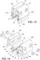
- FIGS. 13 and 14 they illustrate an assembly similar to the ones described above, but with a tightening and fastening component 4 comprising at least two parts 40a-40b that can be approached or moved apart from each other between a moved-apart inoperative position (see figure 14 ) and at least one approached or fitted tightening position (see figure 13 ) of two gripping and coupling components 3 one towards the other and close to the respective portions of a panel 2a, 2b or superimposed ends 2c, 2d of two adjacent panels 2a, 2b.
- Such assembly 1 further comprises at least one locking component in approached position of the two parts 40a, 40b or at least one component 41, 42 for the controlled approaching of the two parts towards the approached tightening position.
- the locking component in approached position or the controlled approaching component comprises one, two or more screws or bolts 41 each of which can be inserted into aligned through holes 40c, 40d each formed in a respective part 40a, 40b, the screws or bolts being adjustably lockable in position, for example by means of nuts 42.
- each part 40a, 40b of the intermediate body 4a comprises a fin 4b1, 4b2 and half or a portion of the intermediate body 4a.
- Each fin 4b1, 4b2 actually wraps and pushes the outer face 3b of a respective gripping and coupling component 3.
- the parts 40a, 40b could be mutually symmetrical or non-symmetrical with respect to a symmetry plane of the tightening and fastening component 4.
- each part 40a, 40b may comprise a respective tubular or block-like segment 4a3, 4a4 and a section of the bottom wall 4d.
- Two gripping and coupling components 3 can be tightened with a such assembly, by arranging them close to a respective portion of an end of a panel 2a, 2b or superimposed ends 2c, 2d of two panels or slabs 2a, 2b and thus arranging the parts 40a, 40b of the tightening and fastening component 4, in a moved-apart inoperative position, wrapping or around the gripping and coupling components 3, and then using or inserting the locking component in approached position or the controlled approaching component 41, 42, this possibly being carried out by inserting the bolt/s 41 into aligned through holes 40c, 40d formed in the parts 40a, 40b and thus locking it/them and pulling it/them by means of a respective bolt 42.
- the parts 40a, 40b of the tightening and fastening component 4 are thus tightened close to the gripping and coupling components 3, each part 40a, 40b preferably close to a respective component 3, so as to press them against the sides of the rib 12 and potentially they are abutted one against the other.
- the approaching-moving apart of the two parts 40a-40b of the tightening and fastening component 4 could be obtained in a direction parallel to the approaching-moving apart direction of the two gripping and coupling components 3 or even differently.
- the parts 40a-40b could also be pivoted to each other and approached through relative angular displacement or a combination of the displacements mentioned above.
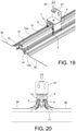
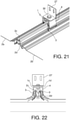
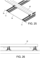
- An assembly according to the present invention may comprise at least one accessory fastened or fastenable by the tightening and fastening component 4, the accessory potentially comprising for example at least one plate 27, 28 if desired L or U-shaped. Regarding this, see figures 15 to 26 .
- the plate 27, 28 could have length or width approximately equivalent to an assembly 1, or extend over a greater dimension, the plate 27, 28 - in this case - could even be fastened to several assemblies 1, for example fastened at the same rib 12 (see figures 19-22 ) or different ribs (see figures 23-26 ) and, for example, parallel.
- the assembly could comprise at least one second bolt or screw or grub screw 29, 30 that can be fitted into the plate 27, 28 and into the tightening and fastening component 4 or, if provided, into the longitudinal seat LS or into the tubular segments 4a3, 4a4 thereof, so as to fasten and lock the accessory to the tightening and fastening component 4.
- such accessory could for example include a solar panel, a snow guard, a life-line, a gangway, a faraday cage, a light strip.
- the plate 27, 28 could be a component of such accessory or that could be fastened or fixed thereto.
- an assembly and a unit according to the present invention can be assembled in a quick and easy manner, by fitting or snap-fitting respective components.
- an assembly and a unit like the one described above can also be disassembled from a panel or from the superimposed ends of two adjacent panels, without ruining neither the assembly nor the panels.
- this solution would allow hindering the sliding of the assembly 1 on a surface, this being extremely advantageous in particular should the surface to be clad be inclined, such as an inclined roof.
Landscapes
- Engineering & Computer Science (AREA)
- Mechanical Engineering (AREA)
- Thermal Sciences (AREA)
- Physics & Mathematics (AREA)
- Life Sciences & Earth Sciences (AREA)
- Sustainable Development (AREA)
- Sustainable Energy (AREA)
- Chemical & Material Sciences (AREA)
- Combustion & Propulsion (AREA)
- General Engineering & Computer Science (AREA)
- Civil Engineering (AREA)
- Structural Engineering (AREA)
- Architecture (AREA)
- Finishing Walls (AREA)
Claims (15)
- Baugruppe zum Verbinden oder Befestigen von Zubehörteilen an Gebäudeverkleidungsplatten oder - tafeln, umfassend:- mindestens zwei getrennte Greif- und Kopplungskomponenten (3), wobei die besagten mindestens zwei Greif- und Kopplungskomponenten (3) eine bei Verwendung innere Fläche (3a), die so angeordnet ist, dass sie an einem jeweiligen Ende eine Platte (2a, 2b) oder übereinanderliegender Enden (2c, 2d) zweier benachbarter Platten oder Tafeln (2a, 2b) anliegt, und eine bei Verwendung äußere Fläche (3b) aufweisen;- mindestens eine Spann- und Befestigungskomponente (4), die so angeordnet ist, dass sie in jeweilige Eingriffsabschnitte (3c) der besagten mindestens zwei Greif- und Kopplungskomponenten (3) eingreift, um sie zueinander hin und nahe jeweiliger Abschnitte eine Platte (2a, 2b) oder übereinanderliegender Enden (2c, 2d) zweier benachbarter Platten (2a, 2b) zu spannen, wobei die besagten Eingriffsabschnitte (3c) auf der besagten äußeren Fläche (3b) oder in einem Bereich zwischen der besagten äußeren Fläche (3b) und der besagten inneren Fläche (3a) begrenzt sind;- wobei die besagte Spann- und Befestigungskomponente (4) mindestens einen Teil aufweist, der so angeordnet ist, dass er das Befestigen eines Zubehörteils ermöglicht, worin die besagte mindestens eine Spann-und Befestigungskomponente (4) einen Zwischenkörper (4a) sowie mindestens zwei Flossen (4b, 4c), die sich jeweils von einem jeweiligen Abschnitt oder Ende des besagten Zwischenkörpers (4a) aus erstrecken, umfasst, um zwischen ihnen einen Aufnahmebereich (HZ) für die besagten mindestens zwei Greif- und Kopplungskomponenten (3) nahe eine Platte (2a,2b) oder übereinanderliegender Enden (2c, 2d) zweier benachbarter Platten (2a, 2b) zu definieren, wobei jede Flosse (4b1, 4b2) Mittel (4c) zum Eingreifen in die Eingriffsabschnitte (3c) einer Greif- und Kopplungskomponente (3) aufweist, worin die besagten Eingriffsmittel (4c) so angeordnet sind, dass sie in die besagten Eingriffsabschnitte (3c) durch Einschnappen eingreifen.
- Baugruppe nach Anspruch 1, worin die besagten Eingriffsmittel (4c) so angeordnet sind, dass sie in die besagten Eingriffsabschnitte (3c) eingreifen, um die besagten mindestens zwei Greif- und Kopplungskomponenten (3) zu dem besagten Zwischenkörper (4a) hin zu ziehen.
- Baugruppe nach Anspruch 1 oder 2, worin die besagten Eingriffsmittel erste Zähne (4c) umfassen, während die besagten Eingriffsabschnitte zweite Zähne (3c) umfassen.
- Baugruppe zum Verbinden oder Befestigen von Zubehörteilen an Gebäudeverkleidungsplatten oder -tafeln, umfassend:- mindestens zwei getrennte Greif- und Kopplungskomponenten (3), wobei die besagten mindestens zwei Greif- und Kopplungskomponenten (3) eine bei Verwendung innere Fläche (3a), die so angeordnet ist, dass sie an einem jeweiligen Ende eine Platte (2a, 2b) oder übereinanderliegender Enden (2c, 2d) zweier benachbarter Platten oder Tafeln (2a, 2b) anliegt, und eine bei Verwendung äußere Fläche (3b) aufweisen;- mindestens eine Spann- und Befestigungskomponente (4), die so angeordnet ist, dass sie in jeweilige Eingriffsabschnitte (3c) der besagten mindestens zwei Greif- und Kopplungskomponenten (3) eingreift, um sie zueinander hin und nahe jeweiliger Abschnitte eine Platte (2a, 2b) oder übereinanderliegender Enden (2c, 2d) zweier benachbarter Platten (2a, 2b) zu spannen, wobei die besagten Eingriffsabschnitte (3c) auf der besagten äußeren Fläche (3b) oder in einem Bereich zwischen der besagten äußeren Fläche (3b) und der besagten inneren Fläche (3a) begrenzt sind;- wobei die besagte Spann- und Befestigungskomponente (4) mindestens einen Teil aufweist, der so angeordnet ist, dass er das Befestigen eines Zubehörteils ermöglicht, worin die besagte mindestens eine Spannund Befestigungskomponente (4) einen Zwischenkörper (4a) sowie mindestens zwei Flossen (4b, 4c), die sich jeweils von einem jeweiligen Abschnitt oder Ende des besagten Zwischenkörpers (4a) aus erstrecken, umfasst, um zwischen ihnen einen Aufnahmebereich (HZ) für die besagten mindestens zwei Greif- und Kopplungskomponenten (3) nahe eine Platte (2a, 2b) oder übereinanderliegender Enden (2c, 2d) zweier benachbarter Platten (2a, 2b) zu definieren, wobei jede Flosse (4b1, 4b2) Mittel (4c) zum Eingreifen in die Eingriffsabschnitte (3c) einer Greif- und Kopplungskomponente (3) aufweist, worin die besagte mindestens eine Spann- und Befestigungskomponente (4) mindestens zwei Teile (40a-40b) umfasst, die einander angenähert oder voneinander wegbewegt werden können zwischen einer auseinanderbewegten unwirksamen Position und mindestens einer angenäherten oder anliegenden Spannposition der besagten mindestens zwei Greif- und Kopplungskomponenten (3) zueinander hin und nahe der jeweiligen Abschnitte eine Platte (2a, 2b) oder übereinanderliegenden Enden (2c, 2d) zweier benachbarter Platten (2a, 2b), wobei die besagte Baugruppe ferner mindestens eine Verriegelungskomponente in angenäherter Position der besagten mindestens zwei Teile (40a, 40b) oder mindestens eine Komponente (41, 42) für die kontrollierte Annäherung der besagten mindestens zwei Teile umfasst, und worin jedes Teil (40a, 40b) der besagten mindestens einen Spann- und Befestigungskomponente (4) eine Flosse (4b1, 4b2) und die Hälfte oder einen Abschnitt des Zwischenkörpers (4a) umfasst, wobei jede Flosse (4b1, 4b2) die äußere Fläche (3b) einer jeweiligen Greif- und Kopplungskomponente (3) umhüllt und drückt.
- Baugruppe nach irgendeinem der vorangegangenen Ansprüche, worin die innere Fläche (3a) der besagten mindestens zwei Greif- und Kopplungskomponenten (3) mindestens einen Vorsprung (3d), der angeordnet ist, um in eine Nut, die durch eine Platte (2a, 2b) oder durch übereinanderliegende Enden (2c, 2d) zweier benachbarter Platten (2a, 2b) definiert ist, einzugreifen und dagegen zu drücken oder eine Nut zum Eingreifen in einen vorstehenden Bereich eine Platte (2a, 2b) oder übereinanderliegender Enden (2c, 2d) zweier benachbarter Platten (2a, 2b) umfasst.
- Baugruppe nach Anspruch 5, wenn abhängig von Anspruch 1, worin sich der besagte Vorsprung (3d) oder die besagte Nut einer ersten Greif- und Kopplungskomponente (3) in eine Richtung zu einer zweiten Greif- und Kopplungskomponente (3), die der ersten gegenüberliegt, und zu dem Zwischenkörper (4a) der besagten Spann- und Befestigungskomponente (4) hin erstreckt.
- Baugruppe nach Anspruch 6, worin die innere Fläche (3a) der besagten mindestens zwei Greif- und Kopplungskomponenten (3) auf einer Seite, bei Verwendung distal von dem Zwischenkörper (4a), zu einer Seite, bei Verwendung proximal zu dem besagten Zwischenkörper (4a), den besagten Vorsprung (3d) oder die besagte Nut, dann einen vertieften Bereich (3e) und einen erhabenen Bereich (3f) oder einen Bereich, der in Bezug auf den besagten vertieften Bereich (3e) versetzt ist, umfasst, sodass der Abstand zwischen den erhabenen Bereichen (3f) der besagten mindestens zwei Greif- und Kopplungskomponenten (3) geringer ist als der Abstand zwischen den vertieften Bereichen (3e) solcher Greifund Kopplungskomponenten (3).
- Baugruppe nach irgendeinem der vorangegangenen Ansprüche, wenn abhängig von Anspruch 1, worin der besagte Zwischenkörper (4a) mindestens einen Längssitz (LS) beinhaltet, der in die dem besagten Aufnahmebereich (HZ) entgegengesetzte Richtung offen ist.
- Baugruppe nach Anspruch 8, worin der besagte Zwischenkörper (4a) zwei röhrenförmige oder blockartige Segmente (4a3, 4a4) umfasst, die untereinander den besagten Längssitz (LS) definieren, wobei die besagten röhrenförmigen oder blockartigen Segmente (4a3, 4a4) mittels einer Bodenwand (4d), die zusammen mit den besagten Flossen (4b1, 4b2) den besagten Aufnahmebereich (HZ) definiert, eine Brückenverbindung sind.
- Baugruppe nach Anspruch 8 oder 9, umfassend mindestens eine erste Madenschraube oder Schraube oder einen ersten Bolzen (25), die/der in den besagten Längssitz (LS) und in ein Durchgangsloch (1), das in der besagten Bodenwand (4d) ausgebildet ist, eingesetzt werden kann, wobei die besagte mindestens eine Madenschraube oder Schraube oder der besagte mindestens eine Bolzen (25) angeordnet ist, um das besagte Platte oder die benachbarten Platten (2a, 2b) zu verformen, um die Spannaktion der besagten mindestens zwei Greif- und Kopplungskomponenten (3) gegeneinander und nahe jeweiliger Abschnitte eine Platte (2a, 2b) oder übereinanderliegender Enden (2c, 2d) zweier benachbarter Platten (2a, 2b) zu erhöhen.
- Baugruppe nach irgendeinem der vorangegangenen Ansprüche, umfassend mindestens einem Zubehörteil, das durch die besagte mindestens eine Spann- und Befestigungskomponente (4) befestigt ist oder befestigt werden kann, wobei das Zubehörteil mindestens eine Platte (27, 28) umfasst.
- Baugruppe nach Anspruch 8 und 11 oder 9 und 11 oder 10 und 11, umfassend mindestens einen zweiten Bolzen oder eine zweite Schraube oder Madenschraube (29, 30), der/die in die besagte Platte (27, 28) und in den besagten Längssitz (LS) oder in die besagten röhrenförmigen oder blockartigen Segmente (4a3, 4a4) eingesetzt werden kann, um das besagte Zubehörteil an der besagten mindestens einen Spann- und Befestigungskomponente (4) zu befestigen und zu verriegeln.
- Gebäudeverkleidungseinheit, umfassend mindestens eine Platte oder zwei benachbarten Platten (2a, 2b) und mindestens eine Verbindungs- oder Befestigungsbaugruppe nach irgendeinem der Ansprüche 1 bis 12, worin mindestens zwei Greif- und Kopplungskomponenten (3) durch die besagte mindestens eine Spann- und Befestigungskomponente (4) nahe jeweiliger Abschnitte eine Platte (2a, 2b) oder übereinanderliegenden Endes (2c, 2d) zweier benachbarter Platten (2a, 2b) gespannt werden.
- Einheit nach Anspruch 13, worin die gekoppelten oder übereinanderliegenden Enden oder Seitenkanten (2c, 2d) benachbarter Platten (2a, 2b) mindestens eine Rippe oder Leiste (12) mit Längserstreckung oder parallel zur Vorne-(le)-Hinten-(lf)-Richtung der besagten mindestens einen Baugruppe (1) definieren, worin, unter Berücksichtigung der Längserstreckungsrichtung der besagten gekoppelten oder übereinanderliegenden Seitenkanten (2c, 2d) zweier Platten (2a, 2b) als die erste Richtung (x-x), die Richtung von einer Seite zur anderen der besagten mindestens einen Rippe (12) als die zweite Richtung (y-y) orthogonal zur ersten Richtung (x-x) und die Richtung orthogonal zur ersten (x-x) und zweiten (y-y) Richtung als die dritte Richtung (z-z), die besagte mindestens eine Rippe (12) einen Querschnitt entlang einer Ebene orthogonal zur ersten Richtung (x-x) aufweist und worin die zweite (y-y) und die dritte (z-z) Richtung konstant entlang der Längserstreckung der Platten (2a, 2b) oder entlang der ersten Richtung (x-x) liegen, und
worin mindestens eine Baugruppe (1) auf der besagten mindestens eine Rippe oder Leiste (12) montiert ist, mit mindestens zwei Greif- und Kopplungskomponenten (3), die einander gegenüberliegend in Bezug auf die Rippe oder Leiste (12) angeordnet sind, und mindestens einer Spann- und Befestigungskomponente (4), das als Stopfen oder Kappe auf den besagten Greif- und Kopplungskomponenten (3) montiert ist, um sie gegen die besagte mindestens eine Rippe oder Leiste (12) zu spannen. - Verfahren zum Montieren einer Baugruppe auf einer Rippe oder Leiste (12), die durch eine Platte oder eine Tafel (2a, 2b) oder durch seitliche Enden oder Kanten (2c, 2d), die durch benachbarte Platten gekuppelt oder übereinanderliegend sind, definiert ist,
die besagte Baugruppe umfassend:- mindestens zwei getrennte Greif- und Kopplungskomponenten (3), wobei die besagten mindestens zwei Greif- und Kopplungskomponenten (3) eine bei Verwendung innere Fläche (3a), die so angeordnet ist, dass sie an einem jeweiligen Ende eine Platte (2a, 2b) oder übereinanderliegender Enden (2c, 2d) zweier benachbarter Platten oder Tafeln (2a, 2b) anliegt, und eine bei Verwendung äußere Fläche (3b) aufweisen;- mindestens eine Spann- und Befestigungskomponente (4), die so angeordnet ist, dass sie in jeweilige Eingriffsabschnitte (3c) der besagten mindestens zwei Greif- und Kopplungskomponenten (3) eingreift, um sie zueinander hin und nahe jeweiliger Abschnitte eine Platte (2a, 2b) oder übereinanderliegender Enden (2c, 2d) zweier benachbarter Platten (2a, 2b) zu spannen, wobei die besagten Eingriffsabschnitte (3c) auf der besagten äußeren Fläche (3b) oder in einem Bereich zwischen der besagten äußeren Fläche (3b) und der besagten inneren Fläche (3a) begrenzt sind;- wobei die besagte Spann- und Befestigungskomponente (4) mindestens einen Teil aufweist, der so angeordnet ist, dass er das Befestigen eines Zubehörteils ermöglicht, worin die besagte mindestens eine Spannund Befestigungskomponente (4) einen Zwischenkörper (4a) sowie mindestens zwei Flossen (4b, 4c), die sich jeweils von einem jeweiligen Abschnitt oder Ende des besagten Zwischenkörpers (4a) aus erstrecken, umfasst, um zwischen ihnen einen Aufnahmebereich (HZ) für die besagten mindestens zwei Greif- und Kopplungskomponenten (3) nahe eine Platte (2a, 2b) oder übereinanderliegender Enden (2c, 2d) zweier benachbarter Platten (2a, 2b) zu definieren, wobei jede Flosse (4b1, 4b2) Mittel (4c) zum Eingreifen in die Eingriffsabschnitte (3c) einer Greif- und Kopplungskomponente (3) aufweist,das besagte Verfahren umfassend die folgenden Schritte:- des Anordnens mindestens einer Greif- und Kopplungskomponente (3), die an einer jeweiligen Seite der Rippe (12) anliegt, sodass die innere Fläche (3a) mindestens einer Greif- und Kopplungskomponente (3) an einer ersten Seite (12a) der Rippe (12) anliegt und die innere Fläche (3a) mindestens einer anderen Greif- und Kopplungskomponente (3) an einer zweiten Seite (12a) der Rippe (12) anliegt, und anschließend- des Tragens des Spann- und Befestigungskomponente (4) mit dem jeweiligen Aufnahmebereich (HZ) zu den Kopplungskomponenten (3) hin gerichtet und somit des Einsetzens der Spann- und Befestigungskomponente (4) um die Greif- und Kopplungskomponenten (3) herum, um den Eingriff der Eingriffsabschnitte (3c) und der Eingriffsmittel (4c) zu bestimmen, oder- des Platzierens von Teilen (40a, 40b) der Spann- und Befestigungskomponente (4), die die Greif- und Kopplungskomponenten (3) umhüllen oder umschließen, und dann des Verwendens oder Einsetzens einer Verriegelungskomponente oder einer kontrollierten Annäherungskomponente (41, 42) zum Spannen der Teile (40a, 40b) der Spann- und Befestigungskomponente (4) nahe der Greif- und Kopplungskomponenten (3), um sie gegen die Seiten der Rippe (12) zu drücken.
Applications Claiming Priority (2)
| Application Number | Priority Date | Filing Date | Title |
|---|---|---|---|
| IT201700128643 | 2017-11-10 | ||
| PCT/IB2018/058548 WO2019092554A1 (en) | 2017-11-10 | 2018-10-31 | Assembly for connecting or fastening accessories to building cladding panels as well as building lining unit |
Publications (2)
| Publication Number | Publication Date |
|---|---|
| EP3707444A1 EP3707444A1 (de) | 2020-09-16 |
| EP3707444B1 true EP3707444B1 (de) | 2022-02-02 |
Family
ID=61527214
Family Applications (1)
| Application Number | Title | Priority Date | Filing Date |
|---|---|---|---|
| EP18811067.0A Active EP3707444B1 (de) | 2017-11-10 | 2018-10-31 | Anordnung zum verbinden oder befestigen von zubehör an gebäudeverkleidungsplatten sowie gebäudeverkleidungseinheit |
Country Status (2)
| Country | Link |
|---|---|
| EP (1) | EP3707444B1 (de) |
| WO (1) | WO2019092554A1 (de) |
Families Citing this family (1)
| Publication number | Priority date | Publication date | Assignee | Title |
|---|---|---|---|---|
| IT201900013254A1 (it) * | 2019-07-29 | 2021-01-29 | Iscom S P A | Staffa o clip di connessione di lamiere di una copertura ad una sottostruttura |
Family Cites Families (5)
| Publication number | Priority date | Publication date | Assignee | Title |
|---|---|---|---|---|
| US6256934B1 (en) * | 1999-06-30 | 2001-07-10 | F. William Alley | Snow guard system having mounting block and clamping pad for securing to a roof seam |
| US6647671B1 (en) * | 2001-09-11 | 2003-11-18 | F. William Alley | Snow guard mounting assembly with a levered locking mechanism |
| DE202007002252U1 (de) * | 2007-02-15 | 2007-04-12 | Zambelli Fertigungs Gmbh & Co | Klemmlasche |
| US8910928B2 (en) * | 2011-05-27 | 2014-12-16 | Gregory A. Header | Flanged material and standing seam clamp |
| JP2014105533A (ja) * | 2012-11-29 | 2014-06-09 | Sanko Metal Ind Co Ltd | 建築用取付材及びその外囲体 |
-
2018
- 2018-10-31 WO PCT/IB2018/058548 patent/WO2019092554A1/en not_active Ceased
- 2018-10-31 EP EP18811067.0A patent/EP3707444B1/de active Active
Also Published As
| Publication number | Publication date |
|---|---|
| WO2019092554A1 (en) | 2019-05-16 |
| EP3707444A1 (de) | 2020-09-16 |
Similar Documents
| Publication | Publication Date | Title |
|---|---|---|
| CA2655027C (en) | Mounting system especially for solar modules | |
| US8074416B2 (en) | Structural members with gripping features and joining arrangements therefor | |
| EP3074173B1 (de) | Stehfalzklemmvorrichtung | |
| AU4528100A (en) | Structural members and joining arrangements therefor | |
| IE86870B1 (en) | Load-bearing bracket | |
| KR20140137879A (ko) | 콘크리트 벽체의 단열재를 포함한 외장재 시공용 앵커 조립체 | |
| KR20140137878A (ko) | 콘크리트 벽체의 단열재를 포함한 외장재 설치를 위한 앵커 조립체의 시공 방법 | |
| WO2019092554A1 (en) | Assembly for connecting or fastening accessories to building cladding panels as well as building lining unit | |
| EP2837751B1 (de) | Plattform zur Verwendung als Fußweg | |
| GB2234540A (en) | Adjustable brickwork or other facade support apparatus | |
| HK40034162B (en) | Assembly for connecting or fastening accessories to building cladding panels as well as building lining unit | |
| HK40034162A (en) | Assembly for connecting or fastening accessories to building cladding panels as well as building lining unit | |
| FI93669C (fi) | Eristävä rakennuslevyjen liitosjärjestely | |
| KR101500313B1 (ko) | 건식 벽돌벽 구조체 및 그 시공방법 | |
| KR101599748B1 (ko) | 건식 벽돌벽 구조체 및 그 시공방법 | |
| WO2005049936A1 (ja) | 鋼材の取付方法及びそれに用いるリップ溝形鋼並びに固定金具 | |
| US9482267B1 (en) | Omni-directional connection assembly | |
| ITRM970602A1 (it) | Dispositivo per l'ancoraggio rapido di impalcature, ponteggi e opere provvisionali per l'edilizia, in particolare aventi struttura tubolare o simile, ad edifici | |
| US20060169849A1 (en) | Quick joint without bolts or accessories for cable hangers | |
| EP1258578A2 (de) | Rohrverbinder | |
| JPH0849406A (ja) | 建築用仮設材支持金具 | |
| EP3452669B1 (de) | System einer abgehängten decke | |
| JPH0473373A (ja) | 足場用パイプ支柱の固定方法 | |
| KR100960943B1 (ko) | 건설공사용 강관 비계. | |
| KR100946360B1 (ko) | 조립식 사다리 프레임과 클램프의 결합방법 |
Legal Events
| Date | Code | Title | Description |
|---|---|---|---|
| STAA | Information on the status of an ep patent application or granted ep patent |
Free format text: STATUS: UNKNOWN |
|
| STAA | Information on the status of an ep patent application or granted ep patent |
Free format text: STATUS: THE INTERNATIONAL PUBLICATION HAS BEEN MADE |
|
| PUAI | Public reference made under article 153(3) epc to a published international application that has entered the european phase |
Free format text: ORIGINAL CODE: 0009012 |
|
| STAA | Information on the status of an ep patent application or granted ep patent |
Free format text: STATUS: REQUEST FOR EXAMINATION WAS MADE |
|
| 17P | Request for examination filed |
Effective date: 20200228 |
|
| AK | Designated contracting states |
Kind code of ref document: A1 Designated state(s): AL AT BE BG CH CY CZ DE DK EE ES FI FR GB GR HR HU IE IS IT LI LT LU LV MC MK MT NL NO PL PT RO RS SE SI SK SM TR |
|
| AX | Request for extension of the european patent |
Extension state: BA ME |
|
| DAV | Request for validation of the european patent (deleted) | ||
| DAX | Request for extension of the european patent (deleted) | ||
| REG | Reference to a national code |
Ref country code: HK Ref legal event code: DE Ref document number: 40034162 Country of ref document: HK |
|
| GRAP | Despatch of communication of intention to grant a patent |
Free format text: ORIGINAL CODE: EPIDOSNIGR1 |
|
| STAA | Information on the status of an ep patent application or granted ep patent |
Free format text: STATUS: GRANT OF PATENT IS INTENDED |
|
| INTG | Intention to grant announced |
Effective date: 20210811 |
|
| GRAS | Grant fee paid |
Free format text: ORIGINAL CODE: EPIDOSNIGR3 |
|
| GRAA | (expected) grant |
Free format text: ORIGINAL CODE: 0009210 |
|
| STAA | Information on the status of an ep patent application or granted ep patent |
Free format text: STATUS: THE PATENT HAS BEEN GRANTED |
|
| AK | Designated contracting states |
Kind code of ref document: B1 Designated state(s): AL AT BE BG CH CY CZ DE DK EE ES FI FR GB GR HR HU IE IS IT LI LT LU LV MC MK MT NL NO PL PT RO RS SE SI SK SM TR |
|
| REG | Reference to a national code |
Ref country code: GB Ref legal event code: FG4D |
|
| REG | Reference to a national code |
Ref country code: CH Ref legal event code: EP Ref country code: AT Ref legal event code: REF Ref document number: 1466675 Country of ref document: AT Kind code of ref document: T Effective date: 20220215 |
|
| REG | Reference to a national code |
Ref country code: DE Ref legal event code: R096 Ref document number: 602018030401 Country of ref document: DE |
|
| REG | Reference to a national code |
Ref country code: IE Ref legal event code: FG4D |
|
| REG | Reference to a national code |
Ref country code: LT Ref legal event code: MG9D |
|
| REG | Reference to a national code |
Ref country code: NL Ref legal event code: MP Effective date: 20220202 |
|
| REG | Reference to a national code |
Ref country code: AT Ref legal event code: MK05 Ref document number: 1466675 Country of ref document: AT Kind code of ref document: T Effective date: 20220202 |
|
| PG25 | Lapsed in a contracting state [announced via postgrant information from national office to epo] |
Ref country code: SE Free format text: LAPSE BECAUSE OF FAILURE TO SUBMIT A TRANSLATION OF THE DESCRIPTION OR TO PAY THE FEE WITHIN THE PRESCRIBED TIME-LIMIT Effective date: 20220202 Ref country code: RS Free format text: LAPSE BECAUSE OF FAILURE TO SUBMIT A TRANSLATION OF THE DESCRIPTION OR TO PAY THE FEE WITHIN THE PRESCRIBED TIME-LIMIT Effective date: 20220202 Ref country code: PT Free format text: LAPSE BECAUSE OF FAILURE TO SUBMIT A TRANSLATION OF THE DESCRIPTION OR TO PAY THE FEE WITHIN THE PRESCRIBED TIME-LIMIT Effective date: 20220602 Ref country code: NO Free format text: LAPSE BECAUSE OF FAILURE TO SUBMIT A TRANSLATION OF THE DESCRIPTION OR TO PAY THE FEE WITHIN THE PRESCRIBED TIME-LIMIT Effective date: 20220502 Ref country code: NL Free format text: LAPSE BECAUSE OF FAILURE TO SUBMIT A TRANSLATION OF THE DESCRIPTION OR TO PAY THE FEE WITHIN THE PRESCRIBED TIME-LIMIT Effective date: 20220202 Ref country code: LT Free format text: LAPSE BECAUSE OF FAILURE TO SUBMIT A TRANSLATION OF THE DESCRIPTION OR TO PAY THE FEE WITHIN THE PRESCRIBED TIME-LIMIT Effective date: 20220202 Ref country code: HR Free format text: LAPSE BECAUSE OF FAILURE TO SUBMIT A TRANSLATION OF THE DESCRIPTION OR TO PAY THE FEE WITHIN THE PRESCRIBED TIME-LIMIT Effective date: 20220202 Ref country code: ES Free format text: LAPSE BECAUSE OF FAILURE TO SUBMIT A TRANSLATION OF THE DESCRIPTION OR TO PAY THE FEE WITHIN THE PRESCRIBED TIME-LIMIT Effective date: 20220202 Ref country code: BG Free format text: LAPSE BECAUSE OF FAILURE TO SUBMIT A TRANSLATION OF THE DESCRIPTION OR TO PAY THE FEE WITHIN THE PRESCRIBED TIME-LIMIT Effective date: 20220502 |
|
| PG25 | Lapsed in a contracting state [announced via postgrant information from national office to epo] |
Ref country code: PL Free format text: LAPSE BECAUSE OF FAILURE TO SUBMIT A TRANSLATION OF THE DESCRIPTION OR TO PAY THE FEE WITHIN THE PRESCRIBED TIME-LIMIT Effective date: 20220202 Ref country code: LV Free format text: LAPSE BECAUSE OF FAILURE TO SUBMIT A TRANSLATION OF THE DESCRIPTION OR TO PAY THE FEE WITHIN THE PRESCRIBED TIME-LIMIT Effective date: 20220202 Ref country code: GR Free format text: LAPSE BECAUSE OF FAILURE TO SUBMIT A TRANSLATION OF THE DESCRIPTION OR TO PAY THE FEE WITHIN THE PRESCRIBED TIME-LIMIT Effective date: 20220503 Ref country code: FI Free format text: LAPSE BECAUSE OF FAILURE TO SUBMIT A TRANSLATION OF THE DESCRIPTION OR TO PAY THE FEE WITHIN THE PRESCRIBED TIME-LIMIT Effective date: 20220202 Ref country code: AT Free format text: LAPSE BECAUSE OF FAILURE TO SUBMIT A TRANSLATION OF THE DESCRIPTION OR TO PAY THE FEE WITHIN THE PRESCRIBED TIME-LIMIT Effective date: 20220202 |
|
| PG25 | Lapsed in a contracting state [announced via postgrant information from national office to epo] |
Ref country code: IS Free format text: LAPSE BECAUSE OF FAILURE TO SUBMIT A TRANSLATION OF THE DESCRIPTION OR TO PAY THE FEE WITHIN THE PRESCRIBED TIME-LIMIT Effective date: 20220602 |
|
| PG25 | Lapsed in a contracting state [announced via postgrant information from national office to epo] |
Ref country code: SM Free format text: LAPSE BECAUSE OF FAILURE TO SUBMIT A TRANSLATION OF THE DESCRIPTION OR TO PAY THE FEE WITHIN THE PRESCRIBED TIME-LIMIT Effective date: 20220202 Ref country code: SK Free format text: LAPSE BECAUSE OF FAILURE TO SUBMIT A TRANSLATION OF THE DESCRIPTION OR TO PAY THE FEE WITHIN THE PRESCRIBED TIME-LIMIT Effective date: 20220202 Ref country code: RO Free format text: LAPSE BECAUSE OF FAILURE TO SUBMIT A TRANSLATION OF THE DESCRIPTION OR TO PAY THE FEE WITHIN THE PRESCRIBED TIME-LIMIT Effective date: 20220202 Ref country code: EE Free format text: LAPSE BECAUSE OF FAILURE TO SUBMIT A TRANSLATION OF THE DESCRIPTION OR TO PAY THE FEE WITHIN THE PRESCRIBED TIME-LIMIT Effective date: 20220202 Ref country code: DK Free format text: LAPSE BECAUSE OF FAILURE TO SUBMIT A TRANSLATION OF THE DESCRIPTION OR TO PAY THE FEE WITHIN THE PRESCRIBED TIME-LIMIT Effective date: 20220202 Ref country code: CZ Free format text: LAPSE BECAUSE OF FAILURE TO SUBMIT A TRANSLATION OF THE DESCRIPTION OR TO PAY THE FEE WITHIN THE PRESCRIBED TIME-LIMIT Effective date: 20220202 |
|
| REG | Reference to a national code |
Ref country code: DE Ref legal event code: R097 Ref document number: 602018030401 Country of ref document: DE |
|
| PG25 | Lapsed in a contracting state [announced via postgrant information from national office to epo] |
Ref country code: AL Free format text: LAPSE BECAUSE OF FAILURE TO SUBMIT A TRANSLATION OF THE DESCRIPTION OR TO PAY THE FEE WITHIN THE PRESCRIBED TIME-LIMIT Effective date: 20220202 |
|
| PLBE | No opposition filed within time limit |
Free format text: ORIGINAL CODE: 0009261 |
|
| STAA | Information on the status of an ep patent application or granted ep patent |
Free format text: STATUS: NO OPPOSITION FILED WITHIN TIME LIMIT |
|
| 26N | No opposition filed |
Effective date: 20221103 |
|
| PG25 | Lapsed in a contracting state [announced via postgrant information from national office to epo] |
Ref country code: SI Free format text: LAPSE BECAUSE OF FAILURE TO SUBMIT A TRANSLATION OF THE DESCRIPTION OR TO PAY THE FEE WITHIN THE PRESCRIBED TIME-LIMIT Effective date: 20220202 |
|
| REG | Reference to a national code |
Ref country code: DE Ref legal event code: R119 Ref document number: 602018030401 Country of ref document: DE |
|
| PG25 | Lapsed in a contracting state [announced via postgrant information from national office to epo] |
Ref country code: MC Free format text: LAPSE BECAUSE OF FAILURE TO SUBMIT A TRANSLATION OF THE DESCRIPTION OR TO PAY THE FEE WITHIN THE PRESCRIBED TIME-LIMIT Effective date: 20220202 |
|
| REG | Reference to a national code |
Ref country code: CH Ref legal event code: PL |
|
| REG | Reference to a national code |
Ref country code: BE Ref legal event code: MM Effective date: 20221031 |
|
| GBPC | Gb: european patent ceased through non-payment of renewal fee |
Effective date: 20221031 |
|
| PG25 | Lapsed in a contracting state [announced via postgrant information from national office to epo] |
Ref country code: LU Free format text: LAPSE BECAUSE OF NON-PAYMENT OF DUE FEES Effective date: 20221031 |
|
| PG25 | Lapsed in a contracting state [announced via postgrant information from national office to epo] |
Ref country code: LI Free format text: LAPSE BECAUSE OF NON-PAYMENT OF DUE FEES Effective date: 20221031 Ref country code: DE Free format text: LAPSE BECAUSE OF NON-PAYMENT OF DUE FEES Effective date: 20230503 Ref country code: CH Free format text: LAPSE BECAUSE OF NON-PAYMENT OF DUE FEES Effective date: 20221031 |
|
| PG25 | Lapsed in a contracting state [announced via postgrant information from national office to epo] |
Ref country code: BE Free format text: LAPSE BECAUSE OF NON-PAYMENT OF DUE FEES Effective date: 20221031 |
|
| PG25 | Lapsed in a contracting state [announced via postgrant information from national office to epo] |
Ref country code: IE Free format text: LAPSE BECAUSE OF NON-PAYMENT OF DUE FEES Effective date: 20221031 Ref country code: GB Free format text: LAPSE BECAUSE OF NON-PAYMENT OF DUE FEES Effective date: 20221031 |
|
| PG25 | Lapsed in a contracting state [announced via postgrant information from national office to epo] |
Ref country code: CY Free format text: LAPSE BECAUSE OF FAILURE TO SUBMIT A TRANSLATION OF THE DESCRIPTION OR TO PAY THE FEE WITHIN THE PRESCRIBED TIME-LIMIT Effective date: 20220202 |
|
| PG25 | Lapsed in a contracting state [announced via postgrant information from national office to epo] |
Ref country code: MK Free format text: LAPSE BECAUSE OF FAILURE TO SUBMIT A TRANSLATION OF THE DESCRIPTION OR TO PAY THE FEE WITHIN THE PRESCRIBED TIME-LIMIT Effective date: 20220202 Ref country code: HU Free format text: LAPSE BECAUSE OF FAILURE TO SUBMIT A TRANSLATION OF THE DESCRIPTION OR TO PAY THE FEE WITHIN THE PRESCRIBED TIME-LIMIT; INVALID AB INITIO Effective date: 20181031 |
|
| PG25 | Lapsed in a contracting state [announced via postgrant information from national office to epo] |
Ref country code: MT Free format text: LAPSE BECAUSE OF FAILURE TO SUBMIT A TRANSLATION OF THE DESCRIPTION OR TO PAY THE FEE WITHIN THE PRESCRIBED TIME-LIMIT Effective date: 20220202 |
|
| PGFP | Annual fee paid to national office [announced via postgrant information from national office to epo] |
Ref country code: IT Payment date: 20251027 Year of fee payment: 8 |
|
| PGFP | Annual fee paid to national office [announced via postgrant information from national office to epo] |
Ref country code: FR Payment date: 20251027 Year of fee payment: 8 |
|
| PGFP | Annual fee paid to national office [announced via postgrant information from national office to epo] |
Ref country code: TR Payment date: 20251007 Year of fee payment: 8 |