EP3707390B2 - Hydraulische steuerung - Google Patents
Hydraulische steuerung Download PDFInfo
- Publication number
- EP3707390B2 EP3707390B2 EP18793223.1A EP18793223A EP3707390B2 EP 3707390 B2 EP3707390 B2 EP 3707390B2 EP 18793223 A EP18793223 A EP 18793223A EP 3707390 B2 EP3707390 B2 EP 3707390B2
- Authority
- EP
- European Patent Office
- Prior art keywords
- hydraulic control
- hydraulic
- wheel
- electric actuator
- circuit board
- Prior art date
- Legal status (The legal status is an assumption and is not a legal conclusion. Google has not performed a legal analysis and makes no representation as to the accuracy of the status listed.)
- Active
Links
Images


Classifications
-
- F—MECHANICAL ENGINEERING; LIGHTING; HEATING; WEAPONS; BLASTING
- F15—FLUID-PRESSURE ACTUATORS; HYDRAULICS OR PNEUMATICS IN GENERAL
- F15B—SYSTEMS ACTING BY MEANS OF FLUIDS IN GENERAL; FLUID-PRESSURE ACTUATORS, e.g. SERVOMOTORS; DETAILS OF FLUID-PRESSURE SYSTEMS, NOT OTHERWISE PROVIDED FOR
- F15B13/00—Details of servomotor systems ; Valves for servomotor systems
- F15B13/02—Fluid distribution or supply devices characterised by their adaptation to the control of servomotors
- F15B13/04—Fluid distribution or supply devices characterised by their adaptation to the control of servomotors for use with a single servomotor
- F15B13/044—Fluid distribution or supply devices characterised by their adaptation to the control of servomotors for use with a single servomotor operated by electrically-controlled means, e.g. solenoids, torque-motors
- F15B13/0444—Fluid distribution or supply devices characterised by their adaptation to the control of servomotors for use with a single servomotor operated by electrically-controlled means, e.g. solenoids, torque-motors with rotary electric motor
-
- F—MECHANICAL ENGINEERING; LIGHTING; HEATING; WEAPONS; BLASTING
- F16—ENGINEERING ELEMENTS AND UNITS; GENERAL MEASURES FOR PRODUCING AND MAINTAINING EFFECTIVE FUNCTIONING OF MACHINES OR INSTALLATIONS; THERMAL INSULATION IN GENERAL
- F16K—VALVES; TAPS; COCKS; ACTUATING-FLOATS; DEVICES FOR VENTING OR AERATING
- F16K31/00—Actuating devices; Operating means; Releasing devices
- F16K31/02—Actuating devices; Operating means; Releasing devices electric; magnetic
- F16K31/04—Actuating devices; Operating means; Releasing devices electric; magnetic using a motor
- F16K31/047—Actuating devices; Operating means; Releasing devices electric; magnetic using a motor characterised by mechanical means between the motor and the valve, e.g. lost motion means reducing backlash, clutches, brakes or return means
-
- H—ELECTRICITY
- H02—GENERATION; CONVERSION OR DISTRIBUTION OF ELECTRIC POWER
- H02K—DYNAMO-ELECTRIC MACHINES
- H02K11/00—Structural association of dynamo-electric machines with electric components or with devices for shielding, monitoring or protection
- H02K11/30—Structural association with control circuits or drive circuits
- H02K11/33—Drive circuits, e.g. power electronics
-
- H—ELECTRICITY
- H02—GENERATION; CONVERSION OR DISTRIBUTION OF ELECTRIC POWER
- H02K—DYNAMO-ELECTRIC MACHINES
- H02K21/00—Synchronous motors having permanent magnets; Synchronous generators having permanent magnets
- H02K21/12—Synchronous motors having permanent magnets; Synchronous generators having permanent magnets with stationary armatures and rotating magnets
- H02K21/14—Synchronous motors having permanent magnets; Synchronous generators having permanent magnets with stationary armatures and rotating magnets with magnets rotating within the armatures
-
- H—ELECTRICITY
- H02—GENERATION; CONVERSION OR DISTRIBUTION OF ELECTRIC POWER
- H02K—DYNAMO-ELECTRIC MACHINES
- H02K7/00—Arrangements for handling mechanical energy structurally associated with dynamo-electric machines, e.g. structural association with mechanical driving motors or auxiliary dynamo-electric machines
- H02K7/10—Structural association with clutches, brakes, gears, pulleys or mechanical starters
- H02K7/116—Structural association with clutches, brakes, gears, pulleys or mechanical starters with gears
-
- F—MECHANICAL ENGINEERING; LIGHTING; HEATING; WEAPONS; BLASTING
- F15—FLUID-PRESSURE ACTUATORS; HYDRAULICS OR PNEUMATICS IN GENERAL
- F15B—SYSTEMS ACTING BY MEANS OF FLUIDS IN GENERAL; FLUID-PRESSURE ACTUATORS, e.g. SERVOMOTORS; DETAILS OF FLUID-PRESSURE SYSTEMS, NOT OTHERWISE PROVIDED FOR
- F15B13/00—Details of servomotor systems ; Valves for servomotor systems
- F15B13/02—Fluid distribution or supply devices characterised by their adaptation to the control of servomotors
- F15B13/06—Fluid distribution or supply devices characterised by their adaptation to the control of servomotors for use with two or more servomotors
- F15B13/08—Assemblies of units, each for the control of a single servomotor only
- F15B13/0803—Modular units
- F15B13/0832—Modular valves
- F15B13/0839—Stacked plate type valves
-
- F—MECHANICAL ENGINEERING; LIGHTING; HEATING; WEAPONS; BLASTING
- F15—FLUID-PRESSURE ACTUATORS; HYDRAULICS OR PNEUMATICS IN GENERAL
- F15B—SYSTEMS ACTING BY MEANS OF FLUIDS IN GENERAL; FLUID-PRESSURE ACTUATORS, e.g. SERVOMOTORS; DETAILS OF FLUID-PRESSURE SYSTEMS, NOT OTHERWISE PROVIDED FOR
- F15B13/00—Details of servomotor systems ; Valves for servomotor systems
- F15B13/02—Fluid distribution or supply devices characterised by their adaptation to the control of servomotors
- F15B13/06—Fluid distribution or supply devices characterised by their adaptation to the control of servomotors for use with two or more servomotors
- F15B13/08—Assemblies of units, each for the control of a single servomotor only
- F15B13/0803—Modular units
- F15B13/0846—Electrical details
- F15B13/0853—Electric circuit boards
-
- F—MECHANICAL ENGINEERING; LIGHTING; HEATING; WEAPONS; BLASTING
- F15—FLUID-PRESSURE ACTUATORS; HYDRAULICS OR PNEUMATICS IN GENERAL
- F15B—SYSTEMS ACTING BY MEANS OF FLUIDS IN GENERAL; FLUID-PRESSURE ACTUATORS, e.g. SERVOMOTORS; DETAILS OF FLUID-PRESSURE SYSTEMS, NOT OTHERWISE PROVIDED FOR
- F15B13/00—Details of servomotor systems ; Valves for servomotor systems
- F15B13/02—Fluid distribution or supply devices characterised by their adaptation to the control of servomotors
- F15B13/06—Fluid distribution or supply devices characterised by their adaptation to the control of servomotors for use with two or more servomotors
- F15B13/08—Assemblies of units, each for the control of a single servomotor only
- F15B13/0803—Modular units
- F15B13/0846—Electrical details
- F15B13/0857—Electrical connecting means, e.g. plugs, sockets
-
- F—MECHANICAL ENGINEERING; LIGHTING; HEATING; WEAPONS; BLASTING
- F15—FLUID-PRESSURE ACTUATORS; HYDRAULICS OR PNEUMATICS IN GENERAL
- F15B—SYSTEMS ACTING BY MEANS OF FLUIDS IN GENERAL; FLUID-PRESSURE ACTUATORS, e.g. SERVOMOTORS; DETAILS OF FLUID-PRESSURE SYSTEMS, NOT OTHERWISE PROVIDED FOR
- F15B13/00—Details of servomotor systems ; Valves for servomotor systems
- F15B13/02—Fluid distribution or supply devices characterised by their adaptation to the control of servomotors
- F15B13/06—Fluid distribution or supply devices characterised by their adaptation to the control of servomotors for use with two or more servomotors
- F15B13/08—Assemblies of units, each for the control of a single servomotor only
- F15B13/0803—Modular units
- F15B13/0846—Electrical details
- F15B13/086—Sensing means, e.g. pressure sensors
-
- F—MECHANICAL ENGINEERING; LIGHTING; HEATING; WEAPONS; BLASTING
- F15—FLUID-PRESSURE ACTUATORS; HYDRAULICS OR PNEUMATICS IN GENERAL
- F15B—SYSTEMS ACTING BY MEANS OF FLUIDS IN GENERAL; FLUID-PRESSURE ACTUATORS, e.g. SERVOMOTORS; DETAILS OF FLUID-PRESSURE SYSTEMS, NOT OTHERWISE PROVIDED FOR
- F15B13/00—Details of servomotor systems ; Valves for servomotor systems
- F15B13/02—Fluid distribution or supply devices characterised by their adaptation to the control of servomotors
- F15B13/04—Fluid distribution or supply devices characterised by their adaptation to the control of servomotors for use with a single servomotor
- F15B13/0401—Valve members; Fluid interconnections therefor
- F15B2013/0409—Position sensing or feedback of the valve member
-
- F—MECHANICAL ENGINEERING; LIGHTING; HEATING; WEAPONS; BLASTING
- F15—FLUID-PRESSURE ACTUATORS; HYDRAULICS OR PNEUMATICS IN GENERAL
- F15B—SYSTEMS ACTING BY MEANS OF FLUIDS IN GENERAL; FLUID-PRESSURE ACTUATORS, e.g. SERVOMOTORS; DETAILS OF FLUID-PRESSURE SYSTEMS, NOT OTHERWISE PROVIDED FOR
- F15B2211/00—Circuits for servomotor systems
- F15B2211/60—Circuit components or control therefor
- F15B2211/665—Methods of control using electronic components
- F15B2211/6656—Closed loop control, i.e. control using feedback
-
- F—MECHANICAL ENGINEERING; LIGHTING; HEATING; WEAPONS; BLASTING
- F16—ENGINEERING ELEMENTS AND UNITS; GENERAL MEASURES FOR PRODUCING AND MAINTAINING EFFECTIVE FUNCTIONING OF MACHINES OR INSTALLATIONS; THERMAL INSULATION IN GENERAL
- F16K—VALVES; TAPS; COCKS; ACTUATING-FLOATS; DEVICES FOR VENTING OR AERATING
- F16K31/00—Actuating devices; Operating means; Releasing devices
- F16K31/44—Mechanical actuating means
- F16K31/53—Mechanical actuating means with toothed gearing
- F16K31/54—Mechanical actuating means with toothed gearing with pinion and rack
-
- H—ELECTRICITY
- H02—GENERATION; CONVERSION OR DISTRIBUTION OF ELECTRIC POWER
- H02K—DYNAMO-ELECTRIC MACHINES
- H02K1/00—Details of the magnetic circuit
- H02K1/06—Details of the magnetic circuit characterised by the shape, form or construction
- H02K1/12—Stationary parts of the magnetic circuit
- H02K1/14—Stator cores with salient poles
-
- H—ELECTRICITY
- H02—GENERATION; CONVERSION OR DISTRIBUTION OF ELECTRIC POWER
- H02K—DYNAMO-ELECTRIC MACHINES
- H02K11/00—Structural association of dynamo-electric machines with electric components or with devices for shielding, monitoring or protection
- H02K11/20—Structural association of dynamo-electric machines with electric components or with devices for shielding, monitoring or protection for measuring, monitoring, testing, protecting or switching
- H02K11/21—Devices for sensing speed or position, or actuated thereby
- H02K11/215—Magnetic effect devices, e.g. Hall-effect or magneto-resistive elements
-
- H—ELECTRICITY
- H02—GENERATION; CONVERSION OR DISTRIBUTION OF ELECTRIC POWER
- H02K—DYNAMO-ELECTRIC MACHINES
- H02K2201/00—Specific aspects not provided for in the other groups of this subclass relating to the magnetic circuits
- H02K2201/15—Sectional machines
-
- H—ELECTRICITY
- H02—GENERATION; CONVERSION OR DISTRIBUTION OF ELECTRIC POWER
- H02K—DYNAMO-ELECTRIC MACHINES
- H02K2211/00—Specific aspects not provided for in the other groups of this subclass relating to measuring or protective devices or electric components
- H02K2211/03—Machines characterised by circuit boards, e.g. pcb
Definitions
- the present invention relates to the field of hydraulic controls, in particular comprising hydraulic valves, each comprising a hydraulic distributor and an electric actuator.
- Hydraulic drives are used in many areas, for example in agricultural vehicles, construction machinery, cranes, and other lifting and handling equipment.
- Some hydraulic controls comprise a plurality of juxtaposed hydraulic valves, each valve formed by a hydraulic distributor coupled to an electric actuator actuating a hydraulic control shaft, in particular a valve slide.
- An electric actuator for controlling hydraulic distributors is described for example in the patent US 7,591,448 .
- the hydraulic valves of a hydraulic control system are arranged side by side, spaced at a distance that the valve actuators must maintain.
- the control shaft of the hydraulic valve is pushed by a pre-loaded spring that moves it into a fail- safe position when the hydraulic system fails.
- the actuator must provide a high dynamic force.
- the actuator Due to the demanding environment in which the actuator is used in many hydraulic applications, it is also important that the actuator is robust and reliable, able to withstand vibration, high temperature changes and shock.
- the cost of the actuator is also an important factor.
- An object of the invention is to provide a compact, high-performance, and reliable hydraulic control.
- a particular object of the invention is to provide a hydraulic control with a flat electric actuator for a hydraulic distributor, having a high torque density for its size and which is economical to manufacture.
- Another object of the invention is to provide an electric actuator for hydraulic control, which is compact, efficient and reliable.
- An object of the invention is achieved by a hydraulic control according to the independent claim.
- a hydraulic control comprising at least one hydraulic valve, each hydraulic valve comprising a hydraulic distributor and an electric actuator.
- the hydraulic distributor comprises a valve spool slidably mounted in a body comprising hydraulic channels.
- the electric actuator is attached to the body of the hydraulic distributor and comprises an electric motor, an electronic circuit comprising a circuit board, a linear displacement output member coupled to the control spool, a reduction gear comprising gear wheels coupling the motor to the output member, and a housing in which the electric motor, the electronic circuit and the reduction gear are mounted.
- the gear wheels include at least a first wheel and a second wheel, the second wheel being disposed on the side of a cover of the housing and the electric motor being mounted in the base of the housing.
- the first wheel includes a ring gear engaging a pinion of the rotor and a pinion engaging a ring gear of the second wheel.
- the circuit board is disposed between the ring gear of the second wheel and the magnet of the rotor of the electric motor.
- the first wheel's crown gear is arranged at the height of the circuit board, in a cutout in the circuit board.
- the use of a closed-loop controlled brushless DC motor makes it possible to transmit stronger force peaks to the valve slide and to work more safely, in particular by having high reliability in the positioning of the output member of the electric actuator.
- a plurality of stacked or juxtaposed hydraulic distributors may comprise a common, single-piece body (comprising hydraulic channels), or a plurality of bodies (e.g., one per valve) assembled together.
- the electric motor comprises a stator and a rotor, the rotor comprising a magnet defining a plurality of rotor poles and the stator comprising a magnetic armature and a plurality of coils mounted on the magnetic armature.
- the circuit board is arranged above an axial end of the rotor magnet, magnetic probes, for example Hall effect probes, being arranged on the circuit board above the magnetic segments of the magnet, the magnetic probes being arranged in an arc around the rotor at an angle ( ⁇ ) of less than 60 degrees.
- the rotor comprises a cylindrical magnet and a yoke arranged coaxially within the cylindrical magnet, the yoke and magnet being mounted in an overmolded plastic support, the support comprising flanges extending radially above the axial ends of the yoke and magnet.
- the motor is a closed-loop controlled brushless DC motor.
- the coils are mounted on branches of the magnetic armature arranged in an arc of less than 180 degrees around the axis of rotation of the rotor, an axis of rotation of the first wheel of the reducer being mounted next to a part of the stator without coils.
- the second wheel comprises a position marker disposed on a face of the ring gear facing the circuit board and a position detector is mounted on the circuit board below the position marker.
- the position detector is in the form of a Hall effect sensor and the position marker is in the form of a ring magnet.
- the second wheel of the reducer comprises a pinion which engages a rack connected to the linear displacement output member.
- conductive wires of the coils are connected to electrical terminals formed from stamped parts inserted into or overmolded by a plastic material integrally forming the base of the housing and supporting the armature and the coils.
- the actuator comprises a connector for connecting the electronic circuit to an external control, a housing of the connector being integrally formed with the base of the housing, electrical terminals of the connector being overmolded in the base of the housing and comprising axially oriented connection portions for connection with the circuit board.
- the magnetic armature and the coils including electrical terminals for connection to a circuit board are overmolded in the plastic material forming the base of the housing.
- the clearance between the outer diameter of the yoke and the inner diameter of the magnet is in a range of 50 to 200 microns.
- the rotor support comprises a pinion integral with the support formed from an injected plastic material.
- the hydraulic control comprises a pre-stressed return spring acting on the valve spool.
- the return spring is mounted at an interface between the body of the hydraulic distributor and the electric actuator, in a housing formed in the housing of the electric actuator.
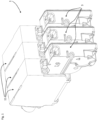
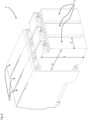
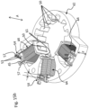
- a hydraulic control 1 comprises a plurality of hydraulic valves 11, 3 juxtaposed or stacked.
- Each hydraulic valve comprises a hydraulic distributor 11 and a corresponding electric actuator 3, a single electric actuator being associated with a single hydraulic distributor.
- Each hydraulic valve comprises a valve spool 13 slidably mounted in a body 19 comprising hydraulic channels 17.
- the position and configuration of the hydraulic channels as well as the profile (not shown) of the valve spool are adapted to the hydraulic function and are known per se and will not be described in further detail herein.
- the number of juxtaposed valves forming the hydraulic control 1 may vary depending on the application. Given the stacked arrangement of the valves, there is an advantage in the distributors as well as the actuators having a small footprint in the direction of juxtaposition.
- the electric actuator 3 therefore has a thickness E limited by the thickness of the hydraulic distributor 11.
- the electric actuator is fixed to the body 19 of the hydraulic distributor on an interface 21 of the body constituting one of the minor faces of the body.
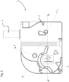
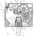
- the electric actuator comprises an electric motor 6, an electronic circuit 10 comprising a circuit board 24, a linear displacement output member 4 coupled to the valve slide 13, a reduction gear 8 comprising gear wheels 22 coupling the motor to the output member, and a housing 2 in which the electric motor 6, the electronic circuit 10 and the reduction gear 8 are mounted.
- the output member 4 is connected to, or integral with, a rack 5 arranged in the housing 2 of the electric actuator.
- the motor 6 of the electric actuator is a closed-loop controlled brushless DC motor.
- a closed-loop controlled brushless DC motor makes it possible to transmit higher force peaks to the valve spool and to work more safely, in particular by having high reliability in positioning the output member of the electric actuator.
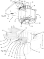
- the hydraulic control 1 may comprise, for each hydraulic valve, a pre-stressed return spring 15.
- the valve spool is pushed by the pre-stressed return spring 15 which moves it into a fail-safe position (so-called "fail safe” position) when the hydraulic system fails.
- the electric actuator must provide a high dynamic force.
- the choice of a closed-loop controlled brushless DC motor makes it possible to meet this requirement reliably, in an economical and compact configuration.
- the return spring 15 is mounted in a housing in the body 19 of the hydraulic distributor 11.
- the return spring 15 is mounted at the interface between the body 19 and the electric actuator, in a housing 23 formed in the housing 2 of the electric actuator.
- the axis of the output member 4 of the electric actuator 3 comprises a coupling part 7a mounted in a chamber 27 of the hydraulic distributor in which the return spring 15 is mounted.
- the chamber 27 is closed by a cap 25 mounted on the body of the hydraulic distributor, the chamber being filled with hydraulic fluid.
- a seal 29 is arranged between an orifice in the wall of the cap 25 and the axis 7a of the output member to ensure sealing between the hydraulic circuit and the electric actuator.
- the output member 4 may be coupled to the valve spool 13 by means of a removable connection configured to absorb positioning tolerances, for example in the form of a ball joint.
- the output member 4 may comprise a partially spherical coupling portion 31 inserted into a housing 33 at the end of the valve spool.
- a play-compensating spring 29 prestressed in the housing 33 presses the coupling portion 31 against a stop in the housing in order to eliminate the positioning play in the transverse direction T between the output member 4 and the valve slide 13.
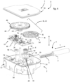
- the housing 2 of the electric actuator comprises a base 14 and a cover 16 which closes the open side of the base.
- the base 14 of the housing forms a volume inside which the motor 6, the reducer 8 and the electronic circuit 10 are mounted.
- the cover 16 and the base 14 can advantageously be made of an injected plastic material, the edge of the cover 16 being welded to the edge of the base 14, for example by ultrasonic or laser welding, in order to ensure a hermetic seal between the cover 16 and the base 14.
- the motor 6 comprises a rotor 18 and a stator 20.
- the motor is in the form of a brushless DC motor.
- the rotor 18 comprises a magnet 30 forming a plurality of magnetic poles, for example a cylindrical magnet having a plurality of magnetized segments of alternating polarities arranged around the circumference of the cylinder.
- the rotor 18 may advantageously comprise a yoke 34 arranged coaxially within the cylindrical magnet, the yoke 34 being formed of a material with high magnetic permeability, such as soft iron.
- the yoke 34 and the magnet 30 are mounted in a support 68 of overmolded plastic, the support comprising flanges 69a, 69b extending radially above the axial ends of the yoke 34 and the magnet 30.
- the outer diameter of the yoke 34 is slightly less than the inner diameter of the magnet 30, the clearance between these two diameters being in a range of 50 to 200 microns, configured to compensate for a difference in thermal expansion between the yoke 34 and the magnet 30.
- the gap between the yoke 34 and the magnet 30 should be as small as possible while allowing sufficient clearance for differences in thermal expansion and also to allow easy assembly of the yoke 34 into the magnet 30.
- Overmolding the radial flanges over the axial ends of the yoke 34 and the magnet 30 advantageously allows the magnet 30 to be secured to the yoke 34 with the smallest desired clearance without requiring the use of glue or other securing means between the yoke 34 and the magnet 30.
- the support 68 may further comprise a pinion 40 secured to the support 68, for example advantageously formed from a plastic material injected at the same time as the support 68.
- the support 68 may be hollow in order to insert an axle 36, bearings 38 being mounted at the ends of the axle 36 in order to support the rotor in rotation in the housing 2.
- the stator 20 comprises a magnetic armature 42 and coils 44 mounted on arms of the magnetic armature 42.
- the magnetic armature 42 is made of a material with high magnetic permeability such as soft iron.
- the teeth 50 of the magnetic armature 42 define a number of magnetic poles.
- the coils 44 are formed by conductive wires connected to electrical terminals 54.
- the electrical terminals 54 may be formed from stamped parts.
- the pair of terminals 54 for the two ends of a wire 45 of a coil can be formed from a single stamped part overmolded by the plastic material supporting the armature 42 and the coils 44, a bridge 55 between the two terminals 54 then being cut after the overmolding operation or when the stamped part is still in the overmolding mold.
- the terminals may also be inserted into the plastic material supporting the armature.
- the electrical terminals 54 may advantageously comprise a connection portion 57 to be crimped to the coil wire, allowing automated and rapid manufacture of the coils and their interconnection to the electronic circuit 10.
- the terminals may advantageously comprise a part in the form of pins 53 oriented in an axial direction A configured to be inserted into complementary conductive holes of a circuit board 24 of the electronic circuit 10.
- the pins 53 are offset by a distance r in a radial direction in order to have a compact arrangement while ensuring sufficient distance between the pins for connection to the printed circuit.
- the magnetic armature 42 and the coils 44 can advantageously be directly overmolded in the plastic material forming the base 14, including the electrical terminals 54 ready to be coupled to the circuit board 24.
- the rotor 6 can be inserted axially into the stator which is directly integrated into the base of the housing.
- the reducer 8 comprises gear wheels 22 comprising a first wheel 46 and a second wheel 48.
- the first wheel 46 comprises a toothed crown 58 engaging the pinion 40 of the rotor 18.
- An axle 59 supporting the rotation of the first wheel 46 is mounted at the ends in housings formed in the base 14 and in the cover 16.
- the second wheel 48 comprises an axle 63 mounted at the ends of the housings formed in the base and the cover.
- axles 59 and 63 like the rotor 18 and the gear wheels 22 as well as the circuit board 24, can all be assembled in an axial direction A in the base 14 to simplify the assembly operations.
- the second wheel 48 of the reducer 8 comprises a pinion 62 which engages the rack 5.
- the rack 5 may be supported at its back by a bearing 79 so that the rack 5 comprises support on both sides opposite to guide them in the transverse direction T of linear movement of the output member 4.
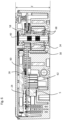
- the toothed crown 60 of the second wheel 48 is arranged on the other side of the circuit board 24 with respect to the magnet 30 of the rotor 18.
- the circuit board 24 advantageously comprises cut-out portions 74, 72, a first cut-out 72 allowing the axial passage of the circuit board 24 to partially circumnavigate the pinion 40 and the toothed crown 58 of the first wheel 46 which is arranged at the height of the circuit board.
- the circuit board 24 can therefore be arranged just above an axial end of the magnet 30 of the rotor 18, Hall effect position sensors 26 being arranged on the circuit board 24 above the magnetic segments 32 of the magnet 30.
- the magnetic probes 26a, 26b, 26c may advantageously be arranged close to one another, the probes being in particular spaced apart by an angle ⁇ around the axis of rotation of the rotor of less than 60 degrees. In other words, the probes are arranged in an arc of a circle around the rotor of less than 60 degrees. In the example illustrated, there are three magnetic probes 26a, 26b, 26c, but in variants it is possible to have two, four, or more probes to detect the position and speed of the rotor. For a rotor formed by 5 pairs of poles, the probes 26a, 26b, 26c may in particular have an angle of 24 degrees between adjacent probes in order to form an electrical angle of 120 degrees.
- the arrangement of the magnetic probes 26a, 26b, 26c according to the embodiment of the invention described above makes it possible to reduce the size of the circuit board 24 and leave more space for the stator 20 and the reducer 8 in order to reduce the size, in particular in the axial direction A of the actuator.
- the magnetic probes 26 make it possible to detect the position and speed of the rotor 18 in a very compact and economical configuration.
- the stator 20 of the motor comprises a magnetic armature 42, three coils 44 mounted on branches of the magnetic armature arranged asymmetrically around the rotor 18, and in particular arranged in an arc of a circle around the rotor 18 of less than 180 degrees. Poles of the stator on the opposite side of the coils 44 are formed by teeth 50 of the armature without coils, this making it possible to have a stator 30 of small diameter on the opposite side of the coils.
- the axis 59 of the first wheel 46 of the reducer 8 is mounted next to the part of the stator 20 without coils in order to have a small distance with the axis of the rotor 18 to reduce the diameter of the first wheel 46, for a compact configuration.
- the teeth 50 may have different widths (in the direction of rotation of the rotor), for example a first series of teeth with a greater width than a second series of intercalated teeth as illustrated in the Figure 15a , or the 50 teeth may all be of identical width as shown in the Figure 15b .
- the ring gear 60 of the second wheel 48 is disposed above the circuit board 24, the pinion 62 of the second wheel 62 extending through a cutout 74 of the circuit board to engage the rack 5 disposed below the circuit board 24.
- the second wheel 48 may advantageously comprise a position marker 64 disposed on a face of the ring gear 60 facing the circuit board 24.
- a position detector 28 may be mounted on the circuit board 24 below the position marker 64.
- the position detector 28 may be in the form of a Hall effect sensor and the position marker 64 may be in the form of a ring magnet, for example a segmented ring magnet allowing the Hall effect sensor to detect the movement of the second wheel 48.
- the position detector 28 of the toothed crown 60 makes it possible to provide the position of the output member 4.
- the integration of the position detector 28 directly on the circuit board 24 makes it possible to have a particularly compact and economical arrangement while ensuring the reliability of positioning of the output member.
- the position marker 64 and the probe can be optical.
- the position marker 64 can comprise light and dark segments and the position detector 28 on the circuit board 24 comprises a light source and an optical sensor for detecting the passage of the segments.
- the electronic circuit 10 may include capacitors 66 used in particular for filtering electrical interference. These capacitors 66 take up a certain volume and may be arranged on the circuit board 24 oriented towards the base 14 of the housing 2, on the same side as the rotor 18.
- the electronic circuit 10 may be connected to an external control by a connector 12, the connector housing being integrally formed with the base 14 of the housing. Electrical terminals 78 of the connector 12 may be overmolded directly into the base 14 of the housing, the terminals 78 comprising connection portions in the form of axially oriented pins 81 for a press-fit type connection with conductive holes of the circuit board 24 when the latter is axially inserted into the base 14 of the housing during its assembly.
- the overmolding of the stator 20 of the motor 6, the connection of the coils 44 of the motor, and the electrical terminals 78 of the connector 12 directly in the base 14 of the housing, also forming the bearings for the rotor bearings as well as the housings for the axes of rotation of the gear wheels in the base makes it possible to provide an economical and very compact actuator.
- the arrangement of the second gear wheel 60 of the reducer 8 above the circuit board 24, engaging the first gear wheel 58 below the circuit board 24, with the pinion 62 passing through a cutout in the board 24, makes it possible to have a small footprint in the axial direction A, while offering a large reduction, which makes it possible to use a brushless motor at high speed. and providing a high residual torque.
- the arrangement of the motor coils as well as the position probes 26a, 26b, 26c of the rotor in a reduced arc of a circle makes it possible to arrange the first gear wheel close to the rotor while keeping the axial height of the actuator low.
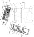
- the electric actuator according to the invention is very compact and is notably characterized by dimension ratios (see figures 8 , 10, 11, 12 , 15 ) described below.
- the ratio e/E of the thickness e of the stator, including the winding thickness, to the thickness E of the electric actuator is greater than 0.45, the direction of measurement of the thickness being the direction of stacking or juxtaposition of the hydraulic valves forming the hydraulic control.
- the ratio L/E of the length L of the electric actuator 3 to the thickness E of the electric actuator is greater than 2.5 and less than 4, the direction of measurement of the length being orthogonal to the direction of stacking of the hydraulic valves forming the hydraulic control and the direction of actuation of the valve slide.
- the ratio H / E of the height H of the electric actuator 3 to the thickness E of the electric actuator is greater than 2 and less than 3.5, the direction of measurement of the height being the direction of actuation of the valve slide.
- examples of electric actuators may have the following dimensions: ⁇ i>Dimensions in mm ⁇ /i> Actuator Stator Thickness (e) Ratios and differences Thickness ( E ) Length ( L ) height ( H ) THE HEY e / E Ee 40 125 100 22 3.1 2.5 0.55 18 32 125 100 16 3.9 3.1 0.50 16 48 125 100 30 2.6 2.1 0.63 18
Landscapes
- Engineering & Computer Science (AREA)
- General Engineering & Computer Science (AREA)
- Power Engineering (AREA)
- Mechanical Engineering (AREA)
- Microelectronics & Electronic Packaging (AREA)
- Physics & Mathematics (AREA)
- Fluid Mechanics (AREA)
- Connection Of Motors, Electrical Generators, Mechanical Devices, And The Like (AREA)
Claims (14)
- Hydraulische Steuerung (1), die mindestens ein Hyraulikventil, wobei jedes Hydraulikventil einen Hydraulikverteiler (11) und einen elektrischen Aktor (3) umfasst, wobei der Hydraulikverteiler einen Körper (19) mit Hydraulikkanälen (17) und einen Ventilschieber (13) umfasst, der in dem Körper (19) verschiebbar gelagert ist, wobei der elektrische Aktor an dem Körper befestigt ist und einen bürstenlosen Gleichstrom-Elektromotor (6) umfasst, der mit geschlossener Schleife gesteuert werden kann, wobei der Motor einen Stator (20) und einen Rotor (18) umfasst, wobei der Rotor einen Magneten (30) umfasst, der eine Vielzahl von Rotorpolen definiert, und der Stator einen Magnetanker (42) und eine Vielzahl von Wicklungen (44) umfasst, die an dem Magnetanker montiert sind, eine elektronische Schaltung (10), die eine Leiterplatte (24) umfasst, ein Ausgangsorgan (4) mit linearer Verlagerung, das an den Ventilschieber gekoppelt ist, ein Reduktionsgetriebe (8), das Zahnräder (22) umfasst, die den Motor an das Ausgangsorgan koppeln, und ein Gehäuse (2) umfasst, in dem der Elektromotor (6), die elektronische Schaltung (10) und das Reduktionsgetriebe (8) montiert sind, wobei die Zahnräder (22) mindestens ein erstes Rad (46) und ein zweites Rad (48) umfassen, wobei das zweite Rad (48) auf der Seite einer Abdeckung (16) des Gehäuses (2) angeordnet ist und der Elektromotor in der Basis (14) des Gehäuses (2) montiert ist, wobei das erste Rad (46) einen Zahnkranz (58), der mit einem Ritzel (40) des Motors ineinandergreift, und ein Ritzel (56) umfasst, das mit einem Zahnkranz (60) des zweiten Rades (48) ineinandergreift, wobei die Leiterplatte (24) zwischen dem Zahnkranz (60) des zweiten (48) Rades und dem Magneten des Rotors des Elektromotors angeordnet ist, der Zahnkranz (58) des ersten Rades (46) in einem Schnitt der Leiterplatte auf der Höhe der Leiterplatte angeordnet ist.
- Hydraulische Steuerung nach Anspruch 1, dadurch gekennzeichnet, dass ein Verhältnis e/E einer Dicke e des Stators des Elektromotors, die die Dicke der Wicklung umfasst, zu einer Dicke E des elektrischen Aktors größer als 0,45 ist, wobei die Richtung der Messung der Dicke eine Stapelungsrichtung der Hydraulikventile ist, die die hydraulische Steuerung bilden.
- Hydraulische Steuerung nach Anspruch 1 oder 2, dadurch gekennzeichnet, dass ein Verhältnis L/E einer Länge L des elektrischen Aktors zu einer Dicke E des elektrischen Aktors größer als 2,5 und kleiner als 4 ist, wobei die Richtung der Messung der Länge orthogonal zu einer Stapelungsrichtung der Hydraulikventile, die die hydraulische Steuerung bilden, und einer Richtung ist, die die Betätigungsrichtung des Ventilschiebers ist.
- Hydraulische Steuerung nach Anspruch 1, 2 oder 3, dadurch gekennzeichnet, dass ein Verhältnis H/E einer Höhe H des elektrischen Aktors zu einer Dicke E des elektrischen Aktors größer als 2 und kleiner als 3,5 ist, wobei die Richtung der Messung der Höhe die Betätigungsrichtung des Ventilschiebers ist.
- Hydraulische Steuerung nach einem der vorhergehenden Ansprüche, dadurch gekennzeichnet, dass das zweite Rad (48) eine Positionsmarke (64) umfasst, die auf einer Seite des Zahnkranzes (60) gegenüber der Leiterplatte (24) angeordnet ist, und ein Positionsdetektor (28) auf der Leiterplatte (24) unter der Positionsmarke (64) montiert ist.
- Hydraulische Steuerung nach dem vorhergehenden Anspruch, dadurch gekennzeichnet, dass der Positionsdetektor (28) die Form eines Hall-Effekt-Sensors aufweist und die Positionsmarke (64) die Form eines ringförmigen Magneten aufweist.
- Hydraulische Steuerung nach einem der vorhergehenden Ansprüche, dadurch gekennzeichnet, dass das zweite Rad (48) des Reduktionsgetriebes ein Ritzel (62) umfasst, das mit einer Zahnstange (5) ineinandergreift, die mit dem Ausgangsorgan (4) mit linearer Verlagerung verbunden ist.
- Hydraulische Steuerung nach einem der vorhergehenden Ansprüche, dadurch gekennzeichnet, dass die Leiterplatte über einem axialen Ende des Magneten (30) des Rotors angeordnet ist, wobei Magnetsonden (26a, 26b, 26c) auf der Leiterplatte (24) über Magnetsegmenten (32) des Magneten angeordnet sind, wobei die Magnetsonden (26a, 26b, 26c) in einem Kreisbogen um den Rotor mit einem Winkel (α) von kleiner als 60 Grad angeordnet sind.
- Hydraulische Steuerung nach einem der vorhergehenden Ansprüche, dadurch gekennzeichnet, dass der Magnet (30) des Rotors (18) eine zylindrische Form aufweist und ein Zylinderkopf (34) koaxial im Inneren des zylindrischen Magneten (30) angeordnet ist, wobei der Zylinderkopf (34) und der Magnet (30) in einem Träger (68) aus abgeformten Kunststoff montiert sind, wobei der Träger (68) Flansche (69a, 69b) umfasst, die sich radial über axialen Enden des Zylinderkopfs des Magneten erstrecken.
- Hydraulische Steuerung nach dem vorhergehenden Anspruch, dadurch gekennzeichnet, dass der Träger (68) ein Ritzel (40) umfasst, das fest mit dem aus einem gespritzten Kunststoff gebildeten Träger verbunden ist.
- Hydraulische Steuerung nach einem der vorhergehenden Ansprüche, dadurch gekennzeichnet, dass die Wicklungen (44) auf Schenkeln des Magnetankers (42) montiert sind, die in einem Bogen von mindestens 180 Grad um die Drehachse des Rotors angeordnet sind, wobei eine Drehachse (59) des ersten Rades (46) des Reduktionsgetriebes neben einem Teil des Stators ohne Wicklungen montiert ist.
- Hydraulische Steuerung nach einem der vorhergehenden Ansprüche, dadurch gekennzeichnet, dass der Motor leitfähige Drähte der Wicklungen umfasst, die mit elektrischen Anschlüssen (54) verbunden sind, die aus gestanzten Teilen gebildet sind, die eingesetzt oder durch einen Kunststoff abgeformt sind und einteilig die Basis des Gehäuses bilden und die Armierung (42) und die Wicklungen (44) tragen.
- Hydraulische Steuerung nach einem der vorhergehenden Ansprüche, dadurch gekennzeichnet, dass der elektrische Aktor einen Verbinder (12) zum Verbinden der elektronischen Schaltung (10) mit einer externen Steuerung umfasst, wobei ein Gehäuse des Verbinders (12) fest mit der Basis des Gehäuses (2) verbunden gebildet ist, wobei die elektrischen Anschlüsse (78) des Verbinders in der Basis des Gehäuses (2) abgeformt sind und Verbindungsteile umfassen, die axial für eine Verbindung mit der Leiterplatte (24) ausgerichtet sind.
- Hydraulische Steuerung nach einem der vorhergehenden Ansprüche, dadurch gekennzeichnet, dass sie eine vorgespannte Rückstellfeder (15) umfasst, die auf den Ventilschieber (13) einwirkt, wobei die Rückstellfeder an einer Grenzfläche zwischen dem Körper (19) des Verteilers und dem elektrischen Aktor in einer Aufnahme (23) montiert ist, die in dem Gehäuse (2) des elektrischen Aktors gebildet ist.
Applications Claiming Priority (2)
| Application Number | Priority Date | Filing Date | Title |
|---|---|---|---|
| EP17201210.6A EP3483454A1 (de) | 2017-11-10 | 2017-11-10 | Hydraulische steuerung |
| PCT/EP2018/079913 WO2019091852A1 (fr) | 2017-11-10 | 2018-11-01 | Commande hydraulique |
Publications (3)
| Publication Number | Publication Date |
|---|---|
| EP3707390A1 EP3707390A1 (de) | 2020-09-16 |
| EP3707390B1 EP3707390B1 (de) | 2022-06-01 |
| EP3707390B2 true EP3707390B2 (de) | 2025-05-21 |
Family
ID=60327103
Family Applications (2)
| Application Number | Title | Priority Date | Filing Date |
|---|---|---|---|
| EP17201210.6A Withdrawn EP3483454A1 (de) | 2017-11-10 | 2017-11-10 | Hydraulische steuerung |
| EP18793223.1A Active EP3707390B2 (de) | 2017-11-10 | 2018-11-01 | Hydraulische steuerung |
Family Applications Before (1)
| Application Number | Title | Priority Date | Filing Date |
|---|---|---|---|
| EP17201210.6A Withdrawn EP3483454A1 (de) | 2017-11-10 | 2017-11-10 | Hydraulische steuerung |
Country Status (4)
| Country | Link |
|---|---|
| US (1) | US11603869B2 (de) |
| EP (2) | EP3483454A1 (de) |
| CN (1) | CN111344496B (de) |
| WO (1) | WO2019091852A1 (de) |
Families Citing this family (7)
| Publication number | Priority date | Publication date | Assignee | Title |
|---|---|---|---|---|
| FR3080234B1 (fr) * | 2018-04-13 | 2021-09-24 | Mmt ag | Actionneur electrique compact lineaire et a chaine cinematique elastique |
| FR3096195B1 (fr) | 2019-05-17 | 2021-05-14 | Moving Magnet Tech | Motoréducteur faible bruit à Moteur électrique dissymétrique |
| DE102020107032A1 (de) | 2020-03-13 | 2021-09-16 | Bucher Hydraulics Gmbh | Hydraulikventilmodul zur sicheren Abschaltung bei Ausfall einer externen Stromversorgung und Verfahren zum Betrieb eines Hydraulikventils |
| FR3113425B1 (fr) * | 2020-08-14 | 2022-07-22 | Bontaz Centre R & D | Distributeur fluidique a fonctionnement ameliore |
| DE102020127383A1 (de) | 2020-10-16 | 2022-04-21 | Bucher Hydraulics Gmbh | Vorsteuergerät für mindestens einen Ventilantrieb eines Hydraulikventils und Verfahren zu deren Betrieb |
| DE102021122793A1 (de) | 2021-09-02 | 2023-03-02 | HELLA GmbH & Co. KGaA | Aktuator und Verfahren zur Herstellung des Aktuators |
| EP4502397A1 (de) * | 2023-08-02 | 2025-02-05 | Thomas Magnete GmbH | Elektromechanischer aktuator und aktuator-ventil-einheit |
Citations (3)
| Publication number | Priority date | Publication date | Assignee | Title |
|---|---|---|---|---|
| US5737968A (en) † | 1996-05-07 | 1998-04-14 | Hardey; Donald H. | Integrated gear motor and method of assembly |
| DE69917432T2 (de) † | 1998-11-24 | 2005-05-19 | Hispano-Suiza | Direkt gesteuerter brennstoffhahn für ein brennstoff- einspritzsystem |
| WO2017013571A2 (en) † | 2015-07-21 | 2017-01-26 | Societe Industrielle De Sonceboz Sa | Electrical actuator with integrated position encoder |
Family Cites Families (13)
| Publication number | Priority date | Publication date | Assignee | Title |
|---|---|---|---|---|
| CA1103298A (en) * | 1977-02-25 | 1981-06-16 | Masami Uchiyama | Electric motor with discrete rotor position and speed sensors |
| FR2754953B1 (fr) * | 1996-10-21 | 1999-02-26 | Moving Magnet Tech | Moteur polyphase, notamment pour l'entrainement d'une aiguille d'un afficheur |
| US20080121830A1 (en) * | 2006-11-27 | 2008-05-29 | Societe Industrielle De Sonceboz S.A. | Hydraulic control valve system |
| US7591448B2 (en) | 2006-11-27 | 2009-09-22 | Societe Industrielle De Sonceboz S.A. | Hydraulic control valve system |
| DE102007031429A1 (de) * | 2007-07-05 | 2009-01-08 | Thomas Magnete Gmbh | Antriebsvorrichtung und Betriebsverfahren für einen Steuerschieber eines hydraulischen Ventils |
| FR2919441B1 (fr) * | 2007-07-24 | 2010-01-29 | Moving Magnet Tech Mmt | Moto-reducteur comportant un moteur electrique polyphase compact |
| US20100060092A1 (en) | 2008-09-08 | 2010-03-11 | Blakesley Patrick B | Brushless direct current actuator |
| US20130305856A1 (en) * | 2012-05-15 | 2013-11-21 | Milan Klimes | Actuator |
| FR3020522B1 (fr) * | 2014-04-25 | 2016-05-06 | Mmt ag | Actionneur electrique |
| DE102014224505A1 (de) * | 2014-12-01 | 2016-06-02 | Robert Bosch Gmbh | Ventil-Betätigungsvorrichtung mit drehsymmetrisch angeordneten Befestigungsmitteln |
| FR3032314B1 (fr) | 2015-02-04 | 2017-01-20 | Mmt Sa | Actionneur de positionnement et procede de fabrication |
| DE102015001883A1 (de) * | 2015-02-13 | 2016-09-01 | Hydac System Gmbh | Ventil mit einem in einem Ventilgehäuse längsverfahrbar geführten Steuerschieber |
| EP3188348A1 (de) * | 2015-12-31 | 2017-07-05 | TDCM Corporation Limited | Antriebsvorrichtung mit schrittmotor |
-
2017
- 2017-11-10 EP EP17201210.6A patent/EP3483454A1/de not_active Withdrawn
-
2018
- 2018-11-01 EP EP18793223.1A patent/EP3707390B2/de active Active
- 2018-11-01 CN CN201880072610.9A patent/CN111344496B/zh active Active
- 2018-11-01 WO PCT/EP2018/079913 patent/WO2019091852A1/fr not_active Ceased
- 2018-11-01 US US16/761,721 patent/US11603869B2/en active Active
Patent Citations (3)
| Publication number | Priority date | Publication date | Assignee | Title |
|---|---|---|---|---|
| US5737968A (en) † | 1996-05-07 | 1998-04-14 | Hardey; Donald H. | Integrated gear motor and method of assembly |
| DE69917432T2 (de) † | 1998-11-24 | 2005-05-19 | Hispano-Suiza | Direkt gesteuerter brennstoffhahn für ein brennstoff- einspritzsystem |
| WO2017013571A2 (en) † | 2015-07-21 | 2017-01-26 | Societe Industrielle De Sonceboz Sa | Electrical actuator with integrated position encoder |
Also Published As
| Publication number | Publication date |
|---|---|
| US11603869B2 (en) | 2023-03-14 |
| WO2019091852A1 (fr) | 2019-05-16 |
| EP3707390B1 (de) | 2022-06-01 |
| EP3707390A1 (de) | 2020-09-16 |
| CN111344496B (zh) | 2022-04-05 |
| US20200340501A1 (en) | 2020-10-29 |
| CN111344496A (zh) | 2020-06-26 |
| EP3483454A1 (de) | 2019-05-15 |
Similar Documents
| Publication | Publication Date | Title |
|---|---|---|
| EP3707390B2 (de) | Hydraulische steuerung | |
| EP0607354B1 (de) | Drei pole aufweisendes elektromagnetisches betätigungselement für pneumatische verteiler | |
| FR2851624A1 (fr) | Palier a roulement instrumente | |
| FR2812139A1 (fr) | Stator pour moteur de demarreur | |
| FR2772470A1 (fr) | Capteur de deplacement rotatif equipe de moyens d'assemblage avec un axe d'entrainement concus pour minimiser les effets d'un desalignement de connexion | |
| EP3732776A1 (de) | Kompaktgetriebemotor | |
| EP2153076B1 (de) | Mit einer indexierung ausgestattete tragevorrichtung | |
| EP3529516B1 (de) | Kompaktgetriebemotor | |
| FR2972514A1 (fr) | Dispositif de compensation d'usure pour engrenage. | |
| FR2813644A1 (fr) | Dispositif de palier a roulement instrumente, notamment pour volant de commande | |
| FR2957463A1 (fr) | Dispositif de connexion electrique etanche a travers une paroi | |
| FR3018010A1 (fr) | Ensemble modulaire de moteur et paliers magnetiques et procede de fabrication | |
| FR3032314A1 (fr) | Actionneur de positionnement et procede de fabrication | |
| FR2945090A1 (fr) | Palier a roulement comportant une enveloppe de maintien d'une des bagues | |
| EP2615726B1 (de) | Rotor, entsprechendes Herstellungsverfahren und entsprechende elektrische Maschine | |
| WO2002037058A1 (fr) | Palier a roulement instrumente pour volant de commande | |
| EP1915763B1 (de) | Elektromagnetisches stellglied mit einer magnetröhre, verwendet zum betätigen eines hydraulischen oder pneumatischen ventils | |
| FR2727177A1 (fr) | Joint homocinetique fixe | |
| EP3913779B1 (de) | Untersetzungsgetriebe, das einen stator mit doppeltem durchmesser umfasst | |
| EP0579560B1 (de) | Schrittmotor | |
| EP2260212A1 (de) | Instrumentiertes lager, anordnung für derartiges lager und entsprechendes montageverfahren | |
| EP3899434B1 (de) | Rotor für induktiven winkelbewegungssensor | |
| FR3154779A1 (fr) | Roue d’engrenage a plage angulaire de fontionnement limitee | |
| EP3033823A2 (de) | Bewegliches teil, insbesondere rotor für eine elektrische maschine und verfahren zur herstellung | |
| WO2017005870A1 (fr) | Actionneur électromagnétique à entrainement direct |
Legal Events
| Date | Code | Title | Description |
|---|---|---|---|
| STAA | Information on the status of an ep patent application or granted ep patent |
Free format text: STATUS: UNKNOWN |
|
| STAA | Information on the status of an ep patent application or granted ep patent |
Free format text: STATUS: THE INTERNATIONAL PUBLICATION HAS BEEN MADE |
|
| PUAI | Public reference made under article 153(3) epc to a published international application that has entered the european phase |
Free format text: ORIGINAL CODE: 0009012 |
|
| STAA | Information on the status of an ep patent application or granted ep patent |
Free format text: STATUS: REQUEST FOR EXAMINATION WAS MADE |
|
| 17P | Request for examination filed |
Effective date: 20200511 |
|
| AK | Designated contracting states |
Kind code of ref document: A1 Designated state(s): AL AT BE BG CH CY CZ DE DK EE ES FI FR GB GR HR HU IE IS IT LI LT LU LV MC MK MT NL NO PL PT RO RS SE SI SK SM TR |
|
| AX | Request for extension of the european patent |
Extension state: BA ME |
|
| DAV | Request for validation of the european patent (deleted) | ||
| DAX | Request for extension of the european patent (deleted) | ||
| GRAP | Despatch of communication of intention to grant a patent |
Free format text: ORIGINAL CODE: EPIDOSNIGR1 |
|
| STAA | Information on the status of an ep patent application or granted ep patent |
Free format text: STATUS: GRANT OF PATENT IS INTENDED |
|
| INTG | Intention to grant announced |
Effective date: 20220216 |
|
| GRAS | Grant fee paid |
Free format text: ORIGINAL CODE: EPIDOSNIGR3 |
|
| GRAA | (expected) grant |
Free format text: ORIGINAL CODE: 0009210 |
|
| STAA | Information on the status of an ep patent application or granted ep patent |
Free format text: STATUS: THE PATENT HAS BEEN GRANTED |
|
| AK | Designated contracting states |
Kind code of ref document: B1 Designated state(s): AL AT BE BG CH CY CZ DE DK EE ES FI FR GB GR HR HU IE IS IT LI LT LU LV MC MK MT NL NO PL PT RO RS SE SI SK SM TR |
|
| REG | Reference to a national code |
Ref country code: GB Ref legal event code: FG4D Free format text: NOT ENGLISH |
|
| REG | Reference to a national code |
Ref country code: AT Ref legal event code: REF Ref document number: 1495538 Country of ref document: AT Kind code of ref document: T Effective date: 20220615 Ref country code: CH Ref legal event code: EP |
|
| REG | Reference to a national code |
Ref country code: IE Ref legal event code: FG4D Free format text: LANGUAGE OF EP DOCUMENT: FRENCH |
|
| REG | Reference to a national code |
Ref country code: DE Ref legal event code: R096 Ref document number: 602018036280 Country of ref document: DE |
|
| REG | Reference to a national code |
Ref country code: LT Ref legal event code: MG9D |
|
| REG | Reference to a national code |
Ref country code: NL Ref legal event code: MP Effective date: 20220601 |
|
| PG25 | Lapsed in a contracting state [announced via postgrant information from national office to epo] |
Ref country code: SE Free format text: LAPSE BECAUSE OF FAILURE TO SUBMIT A TRANSLATION OF THE DESCRIPTION OR TO PAY THE FEE WITHIN THE PRESCRIBED TIME-LIMIT Effective date: 20220601 Ref country code: NO Free format text: LAPSE BECAUSE OF FAILURE TO SUBMIT A TRANSLATION OF THE DESCRIPTION OR TO PAY THE FEE WITHIN THE PRESCRIBED TIME-LIMIT Effective date: 20220901 Ref country code: LT Free format text: LAPSE BECAUSE OF FAILURE TO SUBMIT A TRANSLATION OF THE DESCRIPTION OR TO PAY THE FEE WITHIN THE PRESCRIBED TIME-LIMIT Effective date: 20220601 Ref country code: HR Free format text: LAPSE BECAUSE OF FAILURE TO SUBMIT A TRANSLATION OF THE DESCRIPTION OR TO PAY THE FEE WITHIN THE PRESCRIBED TIME-LIMIT Effective date: 20220601 Ref country code: GR Free format text: LAPSE BECAUSE OF FAILURE TO SUBMIT A TRANSLATION OF THE DESCRIPTION OR TO PAY THE FEE WITHIN THE PRESCRIBED TIME-LIMIT Effective date: 20220902 Ref country code: FI Free format text: LAPSE BECAUSE OF FAILURE TO SUBMIT A TRANSLATION OF THE DESCRIPTION OR TO PAY THE FEE WITHIN THE PRESCRIBED TIME-LIMIT Effective date: 20220601 Ref country code: ES Free format text: LAPSE BECAUSE OF FAILURE TO SUBMIT A TRANSLATION OF THE DESCRIPTION OR TO PAY THE FEE WITHIN THE PRESCRIBED TIME-LIMIT Effective date: 20220601 Ref country code: BG Free format text: LAPSE BECAUSE OF FAILURE TO SUBMIT A TRANSLATION OF THE DESCRIPTION OR TO PAY THE FEE WITHIN THE PRESCRIBED TIME-LIMIT Effective date: 20220901 |
|
| REG | Reference to a national code |
Ref country code: AT Ref legal event code: MK05 Ref document number: 1495538 Country of ref document: AT Kind code of ref document: T Effective date: 20220601 |
|
| PG25 | Lapsed in a contracting state [announced via postgrant information from national office to epo] |
Ref country code: RS Free format text: LAPSE BECAUSE OF FAILURE TO SUBMIT A TRANSLATION OF THE DESCRIPTION OR TO PAY THE FEE WITHIN THE PRESCRIBED TIME-LIMIT Effective date: 20220601 Ref country code: PL Free format text: LAPSE BECAUSE OF FAILURE TO SUBMIT A TRANSLATION OF THE DESCRIPTION OR TO PAY THE FEE WITHIN THE PRESCRIBED TIME-LIMIT Effective date: 20220601 Ref country code: LV Free format text: LAPSE BECAUSE OF FAILURE TO SUBMIT A TRANSLATION OF THE DESCRIPTION OR TO PAY THE FEE WITHIN THE PRESCRIBED TIME-LIMIT Effective date: 20220601 |
|
| PG25 | Lapsed in a contracting state [announced via postgrant information from national office to epo] |
Ref country code: NL Free format text: LAPSE BECAUSE OF FAILURE TO SUBMIT A TRANSLATION OF THE DESCRIPTION OR TO PAY THE FEE WITHIN THE PRESCRIBED TIME-LIMIT Effective date: 20220601 |
|
| PG25 | Lapsed in a contracting state [announced via postgrant information from national office to epo] |
Ref country code: SM Free format text: LAPSE BECAUSE OF FAILURE TO SUBMIT A TRANSLATION OF THE DESCRIPTION OR TO PAY THE FEE WITHIN THE PRESCRIBED TIME-LIMIT Effective date: 20220601 Ref country code: SK Free format text: LAPSE BECAUSE OF FAILURE TO SUBMIT A TRANSLATION OF THE DESCRIPTION OR TO PAY THE FEE WITHIN THE PRESCRIBED TIME-LIMIT Effective date: 20220601 Ref country code: RO Free format text: LAPSE BECAUSE OF FAILURE TO SUBMIT A TRANSLATION OF THE DESCRIPTION OR TO PAY THE FEE WITHIN THE PRESCRIBED TIME-LIMIT Effective date: 20220601 Ref country code: PT Free format text: LAPSE BECAUSE OF FAILURE TO SUBMIT A TRANSLATION OF THE DESCRIPTION OR TO PAY THE FEE WITHIN THE PRESCRIBED TIME-LIMIT Effective date: 20221003 Ref country code: EE Free format text: LAPSE BECAUSE OF FAILURE TO SUBMIT A TRANSLATION OF THE DESCRIPTION OR TO PAY THE FEE WITHIN THE PRESCRIBED TIME-LIMIT Effective date: 20220601 Ref country code: CZ Free format text: LAPSE BECAUSE OF FAILURE TO SUBMIT A TRANSLATION OF THE DESCRIPTION OR TO PAY THE FEE WITHIN THE PRESCRIBED TIME-LIMIT Effective date: 20220601 Ref country code: AT Free format text: LAPSE BECAUSE OF FAILURE TO SUBMIT A TRANSLATION OF THE DESCRIPTION OR TO PAY THE FEE WITHIN THE PRESCRIBED TIME-LIMIT Effective date: 20220601 |
|
| PG25 | Lapsed in a contracting state [announced via postgrant information from national office to epo] |
Ref country code: IS Free format text: LAPSE BECAUSE OF FAILURE TO SUBMIT A TRANSLATION OF THE DESCRIPTION OR TO PAY THE FEE WITHIN THE PRESCRIBED TIME-LIMIT Effective date: 20221001 |
|
| REG | Reference to a national code |
Ref country code: DE Ref legal event code: R026 Ref document number: 602018036280 Country of ref document: DE |
|
| PLBI | Opposition filed |
Free format text: ORIGINAL CODE: 0009260 |
|
| PLAB | Opposition data, opponent's data or that of the opponent's representative modified |
Free format text: ORIGINAL CODE: 0009299OPPO |
|
| PLAX | Notice of opposition and request to file observation + time limit sent |
Free format text: ORIGINAL CODE: EPIDOSNOBS2 |
|
| PG25 | Lapsed in a contracting state [announced via postgrant information from national office to epo] |
Ref country code: AL Free format text: LAPSE BECAUSE OF FAILURE TO SUBMIT A TRANSLATION OF THE DESCRIPTION OR TO PAY THE FEE WITHIN THE PRESCRIBED TIME-LIMIT Effective date: 20220601 |
|
| 26 | Opposition filed |
Opponent name: HOEFER & PARTNER PATENTANWAELTE MBB Effective date: 20230228 |
|
| R26 | Opposition filed (corrected) |
Opponent name: HOEFER & PARTNER PATENTANWAELTE MBB Effective date: 20230228 |
|
| PG25 | Lapsed in a contracting state [announced via postgrant information from national office to epo] |
Ref country code: DK Free format text: LAPSE BECAUSE OF FAILURE TO SUBMIT A TRANSLATION OF THE DESCRIPTION OR TO PAY THE FEE WITHIN THE PRESCRIBED TIME-LIMIT Effective date: 20220601 |
|
| PG25 | Lapsed in a contracting state [announced via postgrant information from national office to epo] |
Ref country code: SI Free format text: LAPSE BECAUSE OF FAILURE TO SUBMIT A TRANSLATION OF THE DESCRIPTION OR TO PAY THE FEE WITHIN THE PRESCRIBED TIME-LIMIT Effective date: 20220601 |
|
| PG25 | Lapsed in a contracting state [announced via postgrant information from national office to epo] |
Ref country code: MC Free format text: LAPSE BECAUSE OF FAILURE TO SUBMIT A TRANSLATION OF THE DESCRIPTION OR TO PAY THE FEE WITHIN THE PRESCRIBED TIME-LIMIT Effective date: 20220601 |
|
| REG | Reference to a national code |
Ref country code: CH Ref legal event code: PL |
|
| P01 | Opt-out of the competence of the unified patent court (upc) registered |
Effective date: 20230601 |
|
| PLBB | Reply of patent proprietor to notice(s) of opposition received |
Free format text: ORIGINAL CODE: EPIDOSNOBS3 |
|
| GBPC | Gb: european patent ceased through non-payment of renewal fee |
Effective date: 20221101 |
|
| REG | Reference to a national code |
Ref country code: BE Ref legal event code: MM Effective date: 20221130 |
|
| PG25 | Lapsed in a contracting state [announced via postgrant information from national office to epo] |
Ref country code: LI Free format text: LAPSE BECAUSE OF NON-PAYMENT OF DUE FEES Effective date: 20221130 Ref country code: CH Free format text: LAPSE BECAUSE OF NON-PAYMENT OF DUE FEES Effective date: 20221130 |
|
| PG25 | Lapsed in a contracting state [announced via postgrant information from national office to epo] |
Ref country code: LU Free format text: LAPSE BECAUSE OF NON-PAYMENT OF DUE FEES Effective date: 20221101 |
|
| PG25 | Lapsed in a contracting state [announced via postgrant information from national office to epo] |
Ref country code: IE Free format text: LAPSE BECAUSE OF NON-PAYMENT OF DUE FEES Effective date: 20221101 Ref country code: GB Free format text: LAPSE BECAUSE OF NON-PAYMENT OF DUE FEES Effective date: 20221101 |
|
| PG25 | Lapsed in a contracting state [announced via postgrant information from national office to epo] |
Ref country code: BE Free format text: LAPSE BECAUSE OF NON-PAYMENT OF DUE FEES Effective date: 20221130 |
|
| PG25 | Lapsed in a contracting state [announced via postgrant information from national office to epo] |
Ref country code: IT Free format text: LAPSE BECAUSE OF FAILURE TO SUBMIT A TRANSLATION OF THE DESCRIPTION OR TO PAY THE FEE WITHIN THE PRESCRIBED TIME-LIMIT Effective date: 20220601 |
|
| PG25 | Lapsed in a contracting state [announced via postgrant information from national office to epo] |
Ref country code: CY Free format text: LAPSE BECAUSE OF FAILURE TO SUBMIT A TRANSLATION OF THE DESCRIPTION OR TO PAY THE FEE WITHIN THE PRESCRIBED TIME-LIMIT Effective date: 20220601 |
|
| PG25 | Lapsed in a contracting state [announced via postgrant information from national office to epo] |
Ref country code: MK Free format text: LAPSE BECAUSE OF FAILURE TO SUBMIT A TRANSLATION OF THE DESCRIPTION OR TO PAY THE FEE WITHIN THE PRESCRIBED TIME-LIMIT Effective date: 20220601 Ref country code: HU Free format text: LAPSE BECAUSE OF FAILURE TO SUBMIT A TRANSLATION OF THE DESCRIPTION OR TO PAY THE FEE WITHIN THE PRESCRIBED TIME-LIMIT; INVALID AB INITIO Effective date: 20181101 |
|
| PG25 | Lapsed in a contracting state [announced via postgrant information from national office to epo] |
Ref country code: MT Free format text: LAPSE BECAUSE OF FAILURE TO SUBMIT A TRANSLATION OF THE DESCRIPTION OR TO PAY THE FEE WITHIN THE PRESCRIBED TIME-LIMIT Effective date: 20220601 |
|
| PG25 | Lapsed in a contracting state [announced via postgrant information from national office to epo] |
Ref country code: BG Free format text: LAPSE BECAUSE OF FAILURE TO SUBMIT A TRANSLATION OF THE DESCRIPTION OR TO PAY THE FEE WITHIN THE PRESCRIBED TIME-LIMIT Effective date: 20220601 |
|
| PG25 | Lapsed in a contracting state [announced via postgrant information from national office to epo] |
Ref country code: BG Free format text: LAPSE BECAUSE OF FAILURE TO SUBMIT A TRANSLATION OF THE DESCRIPTION OR TO PAY THE FEE WITHIN THE PRESCRIBED TIME-LIMIT Effective date: 20220601 |
|
| PGFP | Annual fee paid to national office [announced via postgrant information from national office to epo] |
Ref country code: DE Payment date: 20241121 Year of fee payment: 7 |
|
| PGFP | Annual fee paid to national office [announced via postgrant information from national office to epo] |
Ref country code: FR Payment date: 20241128 Year of fee payment: 7 |
|
| PUAH | Patent maintained in amended form |
Free format text: ORIGINAL CODE: 0009272 |
|
| STAA | Information on the status of an ep patent application or granted ep patent |
Free format text: STATUS: PATENT MAINTAINED AS AMENDED |
|
| 27A | Patent maintained in amended form |
Effective date: 20250521 |
|
| AK | Designated contracting states |
Kind code of ref document: B2 Designated state(s): AL AT BE BG CH CY CZ DE DK EE ES FI FR GB GR HR HU IE IS IT LI LT LU LV MC MK MT NL NO PL PT RO RS SE SI SK SM TR |
|
| REG | Reference to a national code |
Ref country code: DE Ref legal event code: R102 Ref document number: 602018036280 Country of ref document: DE |
|
| PG25 | Lapsed in a contracting state [announced via postgrant information from national office to epo] |
Ref country code: TR Free format text: LAPSE BECAUSE OF FAILURE TO SUBMIT A TRANSLATION OF THE DESCRIPTION OR TO PAY THE FEE WITHIN THE PRESCRIBED TIME-LIMIT Effective date: 20220601 |