EP3706593B1 - Kosmetikapplikator und verfahren zur verwendung davon - Google Patents
Kosmetikapplikator und verfahren zur verwendung davon Download PDFInfo
- Publication number
- EP3706593B1 EP3706593B1 EP18875261.2A EP18875261A EP3706593B1 EP 3706593 B1 EP3706593 B1 EP 3706593B1 EP 18875261 A EP18875261 A EP 18875261A EP 3706593 B1 EP3706593 B1 EP 3706593B1
- Authority
- EP
- European Patent Office
- Prior art keywords
- applicator
- cosmetic
- movable element
- elongate body
- user
- Prior art date
- Legal status (The legal status is an assumption and is not a legal conclusion. Google has not performed a legal analysis and makes no representation as to the accuracy of the status listed.)
- Active
Links
Images


Classifications
-
- A—HUMAN NECESSITIES
- A45—HAND OR TRAVELLING ARTICLES
- A45D—HAIRDRESSING OR SHAVING EQUIPMENT; EQUIPMENT FOR COSMETICS OR COSMETIC TREATMENTS, e.g. FOR MANICURING OR PEDICURING
- A45D40/00—Casings or accessories specially adapted for storing or handling solid or pasty toiletry or cosmetic substances, e.g. shaving soaps or lipsticks
- A45D40/26—Appliances specially adapted for applying pasty paint, e.g. using roller, using a ball
- A45D40/262—Appliances specially adapted for applying pasty paint, e.g. using roller, using a ball using a brush or the like
-
- A—HUMAN NECESSITIES
- A45—HAND OR TRAVELLING ARTICLES
- A45D—HAIRDRESSING OR SHAVING EQUIPMENT; EQUIPMENT FOR COSMETICS OR COSMETIC TREATMENTS, e.g. FOR MANICURING OR PEDICURING
- A45D2/00—Hair-curling or hair-waving appliances ; Appliances for hair dressing treatment not otherwise provided for
- A45D2/48—Eyelash curlers; Eyebrow curlers
-
- A—HUMAN NECESSITIES
- A45—HAND OR TRAVELLING ARTICLES
- A45D—HAIRDRESSING OR SHAVING EQUIPMENT; EQUIPMENT FOR COSMETICS OR COSMETIC TREATMENTS, e.g. FOR MANICURING OR PEDICURING
- A45D40/00—Casings or accessories specially adapted for storing or handling solid or pasty toiletry or cosmetic substances, e.g. shaving soaps or lipsticks
-
- A—HUMAN NECESSITIES
- A45—HAND OR TRAVELLING ARTICLES
- A45D—HAIRDRESSING OR SHAVING EQUIPMENT; EQUIPMENT FOR COSMETICS OR COSMETIC TREATMENTS, e.g. FOR MANICURING OR PEDICURING
- A45D33/00—Containers or accessories specially adapted for handling powdery toiletry or cosmetic substances
-
- A—HUMAN NECESSITIES
- A45—HAND OR TRAVELLING ARTICLES
- A45D—HAIRDRESSING OR SHAVING EQUIPMENT; EQUIPMENT FOR COSMETICS OR COSMETIC TREATMENTS, e.g. FOR MANICURING OR PEDICURING
- A45D34/00—Containers or accessories specially adapted for handling liquid toiletry or cosmetic substances, e.g. perfumes
- A45D34/04—Appliances specially adapted for applying liquid, e.g. using roller or ball
- A45D34/042—Appliances specially adapted for applying liquid, e.g. using roller or ball using a brush or the like
-
- A—HUMAN NECESSITIES
- A45—HAND OR TRAVELLING ARTICLES
- A45D—HAIRDRESSING OR SHAVING EQUIPMENT; EQUIPMENT FOR COSMETICS OR COSMETIC TREATMENTS, e.g. FOR MANICURING OR PEDICURING
- A45D44/00—Other cosmetic or toiletry articles, e.g. for hairdressers' rooms
-
- A—HUMAN NECESSITIES
- A46—BRUSHWARE
- A46B—BRUSHES
- A46B5/00—Brush bodies; Handles integral with brushware
- A46B5/0004—Additional brush head
- A46B5/0012—Brushes with two or more heads on the same end of a handle for simultaneous use, e.g. cooperating with each-other
-
- A—HUMAN NECESSITIES
- A46—BRUSHWARE
- A46B—BRUSHES
- A46B5/00—Brush bodies; Handles integral with brushware
- A46B5/0004—Additional brush head
- A46B5/0016—Brushes with heads on opposite sides or ends of a handle not intended for simultaneous use
-
- A—HUMAN NECESSITIES
- A46—BRUSHWARE
- A46B—BRUSHES
- A46B9/00—Arrangements of the bristles in the brush body
- A46B9/02—Position or arrangement of bristles in relation to surface of the brush body, e.g. inclined, in rows, in groups
- A46B9/021—Position or arrangement of bristles in relation to surface of the brush body, e.g. inclined, in rows, in groups arranged like in cosmetics brushes, e.g. mascara, nail polish, eye shadow
-
- A—HUMAN NECESSITIES
- A45—HAND OR TRAVELLING ARTICLES
- A45D—HAIRDRESSING OR SHAVING EQUIPMENT; EQUIPMENT FOR COSMETICS OR COSMETIC TREATMENTS, e.g. FOR MANICURING OR PEDICURING
- A45D2200/00—Details not otherwise provided for in A45D
- A45D2200/10—Details of applicators
- A45D2200/1009—Applicators comprising a pad, tissue, sponge, or the like
- A45D2200/1018—Applicators comprising a pad, tissue, sponge, or the like comprising a pad, i.e. a cushion-like mass of soft material, with or without gripping means
-
- A—HUMAN NECESSITIES
- A45—HAND OR TRAVELLING ARTICLES
- A45D—HAIRDRESSING OR SHAVING EQUIPMENT; EQUIPMENT FOR COSMETICS OR COSMETIC TREATMENTS, e.g. FOR MANICURING OR PEDICURING
- A45D2200/00—Details not otherwise provided for in A45D
- A45D2200/10—Details of applicators
- A45D2200/1072—Eyeliners
-
- A—HUMAN NECESSITIES
- A45—HAND OR TRAVELLING ARTICLES
- A45D—HAIRDRESSING OR SHAVING EQUIPMENT; EQUIPMENT FOR COSMETICS OR COSMETIC TREATMENTS, e.g. FOR MANICURING OR PEDICURING
- A45D2200/00—Details not otherwise provided for in A45D
- A45D2200/25—Kits
-
- A—HUMAN NECESSITIES
- A46—BRUSHWARE
- A46B—BRUSHES
- A46B2200/00—Brushes characterized by their functions, uses or applications
- A46B2200/10—For human or animal care
- A46B2200/1046—Brush used for applying cosmetics
-
- A—HUMAN NECESSITIES
- A46—BRUSHWARE
- A46B—BRUSHES
- A46B2200/00—Brushes characterized by their functions, uses or applications
- A46B2200/10—For human or animal care
- A46B2200/1046—Brush used for applying cosmetics
- A46B2200/1053—Cosmetics applicator specifically for mascara
Definitions
- Chin boss 7 will be understood to be the recent of the chin of a user 1.
- Each cheek bone center 8, 8 is provided and is also understood to be the main arcuate apex of the cheek bone of a user 1.
- Respective eye cover folds 9, 9 extend above the actual eye 4, 4, of each user and may have varying structures that differ depending upon the user 1.
- Each eye cover fold 9 will be understood to be the skin portion above each eye 4 before reaching a respective eyebrow 2.
- Below each eye 4, 4, is a respective eye lower fold 10, 10 which will be understood generally as the skin portion below each eye 4 before reaching a respective cheek bone center 8.
- Each cover fold 9 and each lower fold 10 may vary by size, contour, shape, and texture by a user.
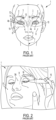
- a user's two-handed technique applies a makeup flair 15a while a finger stretches (see arrows) the eye cover fold 9 into a linear form.
- a user's two-handed technique applies a makeup brush 15b to the lower eyelid fold 10 proximate lower eyelid contact surface 11 while using a one-hand technique and a finger (shown) positioned at a random point on a user's cheek region.
- a crease 13 is shown that is generally parallel and clearly defined providing a 'shadow' effect to the upper eye lid and within the eye cover fold 9 between eye 4 and eyebrow 2.
- a cosmetic system comprising an elongate positioning support system adjustably secured to an application member; at least one of the elongate positioning support system and the application member comprising means for replaceably receiving one of a plurality of tip end members; and the elongate positioning system comprising means for adaptively securing the application member whereby the tip end member is adjustably positioned relative to a distal end member of the cosmetic system.
- an adaptable cosmetic system not belonging to the present invention, that comprises: an elongate positioning support system adjustably secured to an application member; at least one of said elongate positioning support system and said application member comprising means for replaceably receiving one of a plurality of tip end members; and said elongate positioning system comprising means for adaptively securing said application member whereby said tip end member is adjustably positioned relative to a distal end member of said cosmetic system.
- Cosmetic system 30 includes an adaptive positioning support system 40 shown in a preferred elongate illustration, and an adaptive application member 50 or application member 50 adjustably and removably secured thereto, as will be discussed.
- Positioning support system 40 has a shaft portion 41 with an top support end 41A and a bottom support end 41B.
- Each respective and alternative top and bottom support ends 41A, 41B includes an adaptive system for releasably receiving alternative applicator tip ends 60 on either end thereof.
- applicator or application member 50 has at least one adaptor end 51.
- Adaptor end 51 includes an adaptive system for releasably receiving alternative applicator tip ends 60 on the end thereof (or where there are two ends, on either end thereof).
- connection system 70 operably connects positioning support system 40 with applicator or application member 50, as shown.
- connecting system 70 is a single member 70C that includes an internal tongue member (not shown) that releasably engages projecting external tongue members 52 whereby a position of applicator 50 is adjustable relative to positioning support system 40.
- Connecting system 70 may include a mechanical linkage with friction tongues (as shown) or may use any other type of friction resistance, compressive clap, threaded fixture, magnetic arrangement or other means for adjustably or fixably securing positioning support system 40 to applicator 50.
- connection system 70 is provided with a top connecting member 70B and a bottom connecting member 70A, each secured to positioning support system 40 and having a friction opening therein whereby a shaft portion 53 of application member 50 is slidably engaged and repositionable.
- connecting system 70 allows applicator or application member 50 to rotate and pivot (see 51A and arrows, e.g. E) relative to the shaft portion 41 of positioning support system 40.
- applicator 50 may be slid anywhere along the length of positioning support system 40 for user convenience, including rotation relative thereto. Additionally (as noted in the right-hand portion of Fig. 7 ) connecting system 70 (in a single pivot arrangement 90) may further allow application member 50 as an entire while to pivot (see arrows) relative to the shaft portion 41 arrangement. As a result, one of skill in the art will understand that applicator 50 has at from two to five degrees of movement relative (sliding along, rotating relative, and tilting relative) to a pivot section.
- applicator tip ends 60 include and adaptive plurality of means for applying a cosmetic composition (blush, toner, paint, or any other form of pigmentation as will be understood by those if skill in the art).
- Applicator tip ends may be any form of brush, pad, applicator, felt end, tip, or any other shape or form that may have a narrow, pointed, flat, round, contoured, plush/soft, hard/firm or any other type of tip end to a cosmetic application that may be adjusted within the scope of the known cosmetic tip ends without limit to the drawings herein.
- applicator tip ends 60 each include an adaptive connecting tip end that is releasably secured to the adaptive end to each end of the applicator end 51, the positioning support system 40, or in other forms suitable to the use of the invention.
- Positioning member 61A includes a releasably secured construction that may fit into any arrangement also receiving a tip end 60.
- Positioning member 61B provides a flexible clamp member that may be secured at any position along shaft portion 41 of positioning support system 40. As noted with either positioning member 61A, 61B, they are used for further removably securing positioning aids 62A, 62B.
- Positioning aid 62A is in the form of a bridge having an elongate shaft portion 62A' and a smooth end 62A" for skin contact proximate cheek bones 8, 8, or any other portion of a user's face (as noted in Figs. 9, 10 , as will be discussed.
- Positioning aid 61B is in the form of a chin rest shaped to reliably position relative to the position of chin boss 7 on a user's face.
- an applicator end 51 of applicator member 50 include replaceable tip ends 60. Additionally, applicator end 51 includes an angle adjustment system 80 that includes the function of along a contact side of respective tip ends 60 to be adjusted relative to the angle of applicator end 51 in a use-condition by a user's finger. Angle adjustment system 80 may be in any sufficient form to achieve the requirement of angle adjustment but may be in the form of a flexible elastomeric material, a pivot axis a toggle arrangement, a spring, a pivot boss, or any other form of arrangement.
- a user may select a narrow tip end 60 for positioning on end of applicator end 51 (e.g., for drawing in with a cosmetic one or more crease line either laterally (away from the midline) or medially (toward the midline) in whole or part) along the eye cover fold region 9 great accuracy and repeatably on either side of the face.
- a user may have preselected a different tip end for securing to a top support end 41A of positioning support system 40 (e.g., a broad applicator brush) so that a user (without repositioning their hand) may use a finger to swing away application member 50, and use tip end 60 to place eye liner or other indicia on the eye cover fold region 9 within increased accuracy and user comfort.
- positioning support system 40 e.g., a broad applicator brush
- tip end 60 to place eye liner or other indicia on the eye cover fold region 9 within increased accuracy and user comfort.
- the present cosmetic system 30 may be used to apply a crease line or eye liner in any order (without limit).
- a user may one handedly or two handedly adjust applicator member 50 and thus the applicator end 51 downwardly, along shaft portion 41 so as to position a narrow cosmetic proximate the lower eye lid contact surface 11, the upper eyelid contact surface 12, or in other areas proximate eye 4 without departure from the scope of the present disclosure.
- a simplified cosmetic applicator is provided in illustrated form pictographically noting that one of the positioning aids 62A, or 62B may be adaptively secured to portions of the positioning support system 40 proximate cheek bone 8 or chin boss 7 allowing adaption and a user's reliably positioning the cosmetic system on a repeatably skeletal structure for day-by-day repetitive and reliable positioning of cosmetics proximate a crease line 13 (or to draw in an artificial crease line 13), eyeliner, blush or for other cosmetic application use.
- the scope of the present disclosure clearly includes a simplified cosmetic system having a positioning support and an application member. It will be further understood that in one alternative aspect of the present disclosure that the positioning support system and applicator member may be mutually formed or merged into a single adaptive arrangement which includes at least the ability apply a cosmetic to a user's face proximate an eye.
- a cosmetic system 30 may be used with or without positioning aids 62, 62A, 62B relative to facial positions.
- a user may grasp shaft portion 41 and position their hand on cheek bone location 8, or by eye-corner 4b, and repeatably apply the cosmetic to the skin uniformly left-side to right-side.
- tip ends 60 may include smoothing or mixing brushes, pads, or foam allowing a user to apply a cosmetic (first step), and conveniently blend a cosmetic (second step) without departing from the scope of the present disclosure.
- kits 100 is provided with an exemplary outer container 101 that may contain optionally portions of cosmetic system 30. Additionally as shown, kit 100 may be provided with additional cosmetics 102 (blush, hue, etc.) in any suitable form, in individual containers or in a joint-formation or in any other convenient form, so that kit 100 may be provided to the consuming public in a combined form. It will be further understood by those of skill in the art that kits 100 may be adaptively arranged to contain more or less of the features and articles disclosed in the present disclosure so as to provide kits having different components and different values all within the scope of the present disclosure.
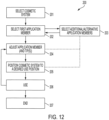
- an optional and adaptive method 200 for using cosmetic system 30 is discussed in a first step 201 where a user selects a desired cosmetic system arrangement and in a step 202 selects desired tip ends 60, 61A, 61B, 62 for receiving securing on positioning support system 40 or application member 50 as discussed herein.
- a related step 203 alternative selections may be made.
- a user adjusts the application member and tip ends to a decided-first-cosmetic use on an eye location (e.g., eye liner, blush, crease-application etc.), and in a next step 205 positions the cosmetic system 30 for a desired use position relative to the facial locations discussed earlier.
- a user applies the cosmetic (e.g., applies an eye cosmetic, then repositions and using a different tip end forms a crease line 13 in a lateral (or medial) manner).
- the cosmetic e.g., applies an eye cosmetic, then repositions and using a different tip end forms a crease line 13 in a lateral (or medial) manner.
- further adjustment may be performed for the same side (left or right) and then a user may use the cosmetic system on the remaining user-side until reaching an end step 207.
- cosmetic system 30 may be returned to a container 101 in a kit 100 for convenient storage and later use.
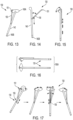
- an alternative adaptive cosmetic system 130 is provided with a positioning support 140 supporting an applicator member 150 having an applicator end 151 (in the form shown of a small diamond-shaped brush), relative to a first tip end 160A (shown in an almond brush) on a first end of positioning support 140 and a second tip end 160B (shown as a blender brush) on the opposing side thereof.
- an applicator member 150 having an applicator end 151 (in the form shown of a small diamond-shaped brush), relative to a first tip end 160A (shown in an almond brush) on a first end of positioning support 140 and a second tip end 160B (shown as a blender brush) on the opposing side thereof.
- applicator member 150 pivots relative to positioning support 140 along a length thereof (at a coupling of applicator member 150 to positioning support 140--the coupling being pivotable so as to also form a fulcrum of the pivoting of applicator member 150) and additionally may slide relatively along the length of support 140 so as to position applicator end 151 in variable positions relative to tip end 160A. Additionally, in one alternative embodiment, a portion of positioning support 140 may telescope in length (e.g., extend along its own length ( Fig. 15 )). Additionally, applicator end 151 is pivotable relative to the securing location along applicator member 150 so that ( Fig.
- applicator tip end 151 can pivot and swivel relative the support shaft of applicator 150, as illustrated in Fig. 14 .
- blender brush tip end 160B, applicator end 151 and tip end 160A will be understood to optionally include the replacement tip end systems of any kind, shape, or sort as discussed herein without limitation, for example the use of a brush, a foam pad, and differently shaped foam members and differently shaped brushes.
- cosmetic system 130 may be compactly stored in the form of a kit arrangement 100A using a container.
- Fig. 17 includes diagrams showing a pivoting motion of cosmetic system 130 in a left-to-right flow process where tip ends may be pivoted, shifted, and curved through arcs-of-use relative to pivot positions, as will be described in further detail below with reference to Figs. 18-23 .
- cosmetic apparatus (system) 130 may be used to apply cosmetics by pivoting applicator end 151 along an arced path, which may be along an edge of tip end 160A (for example, an almond brush).
- applicator member 150 having applicator end 151 may be attached to cosmetic apparatus 130 by a pivotable coupling 155 so that applicator end 151 can be pivoted from one side along a top edge of tip end 160A to the other side, as shown in Fig. 17 , and vice versa, whereby pivotable coupling 155 also forms a fulcrum for the pivoting of applicator member 150.
- tip end 160A may be replaceable so that elements having different shapes, sizes, etc., (for example, an almond brush of a different size or a differently shaped brush) may be used to trace different cosmetic applications.
- elements having different shapes, sizes, etc. for example, an almond brush of a different size or a differently shaped brush
- almond brushes of different sizes and shapes may be provided to accommodate users having different eye sizes and shapes, as illustrated in Fig. 5 .
- the pivotable coupling 155 for applicator end 151 may be slidable along a length of positioning support 140 to accommodate different uses.
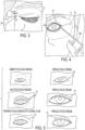
- Fig, 18 illustrates cosmetics to an eyelid region 9 applied to create/supplement a crease line 13 by the pivoting motion shown in Fig. 17 for applicator end 151 in accordance with an exemplary embodiment.
- tip end 160A- for example, an almond brush--may be placed over the eyelid of the user to serve as a stationary anchor for applicator 130.
- the pivoting motion of applicator end 151 along an edge of tip end 160A results in cosmetics being applied to a user's eyelid region 9 along a substantially arced path that would correspond to a natural or artificial crease line 13.
- Fig. 19 illustrates cosmetics applied to a user's eyelid region 9 using tip end 160A with applicator member 150 pivoted away from positioning support 140, as shown in Fig. 14 , in accordance with an exemplary embodiment.
- tip end 160A may be used to apply cosmetics along a region proximate the eyelashes.
- Fig. 19 includes two examples of cosmetics being applied to regions of varying proportions and shapes.
- Fig. 20 illustrates a repeat of the pivoting motion cosmetics application shown in Fig. 18 and the tip end 160A cosmetics application shown in Fig. 19 for the user's other eye according to an exemplary embodiment.
- Fig. 21 illustrates the use of tip end 160A for applying the cosmetics shown in Fig. 19 in accordance with an exemplary embodiment.
- tip end 160A may be used to apply cosmetics along a region proximate the eyelashes with applicator member 150 pivoted away from positioning support 140 so that it (and applicator end 151) does not obstruct the cosmetics application using tip end 160A.
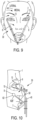
- Fig. 22 illustrates applicator end 151 being used to apply cosmetics proximate the eyelashes on a lower eyelid with applicator member 150 pivoted away from positioning support 140 according to an exemplary embodiment.
- Fig. 23 illustrates second tip end 160B being used as a blender for blending already-applied cosmetics in accordance with an exemplary embodiment.
- applicator member 150 may be packed close to positioning support 140 in a storage configuration, for example as shown in Figs. 15 and 16 , when second tip end 160B is being used.
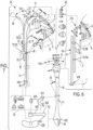
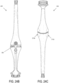
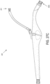
- Figs. 24A-C are perspective, back, and front views, respectively, of a cosmetic applicator 230 shown with a movable element (or "applicator or application member") 250 in accordance with an exemplary embodiment of the invention.
- cosmetic applicator 230 comprises an elongate main body 240 for a user to hold in a self-application of cosmetics according to the procedures described above--for example, as illustrated in Figs. 17-23 .
- main body 240 may comprise a pair of relatively flat surfaces 270a and 270b on respective sides.
- An elongate opening 280 for accommodating an attachment arm 255 of movable element 250 is disposed across a back portion of main body 240 proximate the flat surfaces 270a and 270b, as illustrated in Figs. 24A and 24B .
- attachment arm 255 of movable element 250 is attached to an internal feature of the main body 240 through elongate opening 280, as will be described in further detail below.
- elongate opening 280 extends across a back portion of main body 240 in order to provide support and to define a movement range of movable element 250.
- movable element 250 may be moved along elongate opening 280 in a side-to-side manner in relation to main body 240 so that applicator head 251 can be moved in an arced side-to-side manner in relation to main applicator 260A for a cosmetic application, for example as illustrated in Figs. 17 and 18 .
- movable element 250 may incorporate a support element 257, which may comprise a polymer, woven, felt, fibrous, or any soft material, and the like, formed in a pad, for contacting and sliding along the outer surface on the back portion of main body 240 as movable element 250 is moved side-to-side.
- Support element 257 may provide a desired amount of friction so that movable element 250 can be moved steadily with constant force during use, which is advantageous for cosmetic applications.
- movable element 250 may further incorporate a tab element 258 comprising a patterned surface.
- Tab element 258 provides a user's finger or thumb a relatively enlarged surface for controlling and moving movable element 250 during use.
- a user may use applicator head 251 for drawing in, with a cosmetic, one or more crease lines either laterally (away from the midline) or medially (toward the midline) in whole or part along the eye cover fold region 9 repeatably and with accuracy on either side of the face.
- crease line application For this crease line application, movable element 250 may be moved side-to-side with a finger on tab element 258 so that applicator head 251 may be used for the application without needing to rotate the main body 240 of cosmetic applicator 230. Consequently, the crease line application may be performed with improved stability and accuracy.
- cosmetic applicator 230 having main body 240 comprises applicator head 251, which may be a small diamond-shaped, oval, flat, or pointed brush, sponge, and the like.
- Main body (or "positioning support") 240 comprises a first tip end main applicator 260A on a first end and a second tip end secondary applicator 260B on the opposing side thereof.
- first tip end main applicator 260A may incorporate a brush, a sponge, and the like, for applying cosmetics.
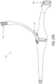
- FIG. 25 is a top view of cosmetic applicator 230 showing exemplary embodiments of main applicator 260A and applicator head 251.
- applicators 251 and 260A may be brushes, sponges, and the like, having approximately corresponding oval shapes with main applicator 260A having a larger coverage for applying cosmetics, say, in region 9 (for example as shown in Fig. 21 ), while applicator head 251 may have a smaller and more precise arrangement for, say, drawing in one or more crease lines in region 9 (for example, as shown in Figs. 18-20 ).
- the size, shape, material, arrangement, orientation, etc., of applicators 251 and 260A may be adjusted and changed without departing from the scope of the invention, as defined in the appended claims.
- FIG. 26 is a bottom view of cosmetic applicator 230 showing an exemplary embodiment of secondary applicator 260B, which may be a blender brush and the like in correspondence with the description above.
- applicator 260B may be a circular brush, sponge, and the like, for blending cosmetics that have already been applied onto a user's face.
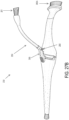
- movable element 250 in addition to the side-to-side swivel movement during use, further incorporates a hinge element 290 and - exemplarily - corresponding shaft 295 for pivoting movable element 250 away from main body 240.
- Fig. 27A is a side view of cosmetic applicator 230 illustrating a relationship between applicators thereof and Figs. 27B-E are perspective and side views of the cosmetic applicator 230 shown in Figs. 24A-26 with movable element 250 pivoted away from main body 240 in respective alternative orientations.
- appliance head 251 may be aligned with applicator 260A so that a plane approximating a cosmetic application surface of applicator head 251 (or an orthogonal axis extending therefrom) may form an angle between about -30 degrees and +30 degrees with a plane approximating a cosmetic application surface of applicator 260A (or an orthogonal axis extending therefrom).
- a plane approximating a cosmetic application surface of applicator head 251 may form an angle between about -10 degrees and +10 degrees with a plane approximating a cosmetic application surface of applicator 260A (or an orthogonal axis extending therefrom)- -or more preferably, the planes/axes may be substantially parallel with one another for applying cosmetics to simulate and/or supplement a crease line, as shown in Figs. 17 and 18 .
- a user may push down on shaft 295 so as to pivot movable element 250 around hinge element 290 and away from main body 240.
- a user may apply cosmetics using main applicator 260A without any obstruction from applicator head 251, for example, as illustrated in Fig. 21 , for applying cosmetics to an upper eyelid.
- a plane approximating a cosmetic application surface of applicator head 251 may form an angle between about 20 and 90 degrees with a plane approximating a cosmetic application surface of applicator 260A (or an orthogonal axis extending therefrom).
- movable element 250 may further comprise a detachable coupling 297 that is also rotatable for orienting applicator head 251 away from main applicator 260A. In this orientation, a user may apply cosmetics using applicator head 251 without any obstruction from main applicator 260A--for example, as illustrated in Fig. 22 , for applying cosmetics to a lower eyelid. As illustrated in Fig.
- a plane approximating a cosmetic application surface of applicator head 251 may form an angle above 90 degrees, preferably between about 90 degrees and about 180 degrees, with a plane approximating a cosmetic application surface of applicator 260A (or an orthogonal axis extending therefrom).
- coupling 297 may provide for completely detaching applicator head 251 from cosmetic applicator 230. Therefore, as an option, a user may apply cosmetics using applicator head 251 without it being attached to cosmetic applicator 230.
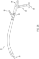
- Fig. 28 is a perspective view illustrating movable element 250 according to an exemplary embodiment.
- Fig. 28 shows movable element 250 without being integrated with cosmetic applicator 230.
- attachment arm 255 of movable element 250 comprises a substantially cylindrical (fulcrum) element 305 on an end for engaging a corresponding element on the internal structure of main body 240 to provide movable element 250 with an anchor and a fulcrum for pivoting movable element 250 for its side-to-side movement--and thereby forming a pivotable coupling for movable element 250 to main body 240 of cosmetic applicator 230.
- tab element 258 is in substantial alignment with fulcrum element 305 so that movement force applied by the user on tab element 258 can steadily pivot movable element 250.
- fulcrum element 305 One of ordinary skill in the art can appreciate that other shapes, orientations, and arrangements of elements may be used in place of element 305 for providing movable element 250 with a steady pivot motion without departing from the scope of the invention.
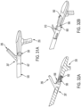
- Figs. 29A and 29B are bottom perspective and top perspective views, respectively, of cosmetic applicator 230 showing the internal engagement between movable element 250 and cosmetic applicator 230 according to an exemplary embodiment.
- main body 240 of cosmetic applicator 230 may comprise two sections 242a and 242b that may be disassembled from each other.
- the respective lengths of sections 242a and 242b may have from a 1-to-1 proportional relationship to about a 3-to-1 relationship--or preferably about 2-to-1 in relative lengths.
- Fig. 29A is a bottom perspective view of cosmetic applicator 230 with bottom portion 242a of main body 240 shown in transparency to illustrate attachment arm 255 and cylindrical element 305 of movable element 250.
- attachment arm 255 of movable element 250 may extend through elongate opening 280 in main body 240 with cylindrical element 305 anchored near an opposite side within main body 240.
- section 242b of main body 240 may comprise one or more openings 310 for receiving corresponding protrusion(s) 315 (shown in Fig. 29B ) on section 242a for engagement in assembling main body 240.
- section 242b may comprise a substantially circular opening 320a (shown in Fig.
- a coating, sleeve, covering, ring, and the like, made from a lubricating and/or resilient material, such as a polymeric material, etc., may be placed between cylindrical element 305 and circular opening 315 for reducing friction, wear and tear, etc. in providing for the rotatable anchor of movable element 250.
- Fig. 29B is a top perspective view of cosmetic applicator 230 with top portion 242b of main body 240 shown in transparency to illustrate attachment arm 255 and cylindrical element 305 of movable element 250.
- attachment arm 255 of movable element 250 may extend through elongate opening 280 in main body 240 with cylindrical element 305 anchored near an opposite side within main body 240.
- section 242a of main body 240 may comprise one or more protrusions 315 for inserting into corresponding opening(s) 310 (shown in Fig. 29A ) in section 242b for engagement in assembling main body 240.
- section 242a may comprise a substantially circular opening 320b (shown in Fig.
- a coating, sleeve, covering, ring, and the like, made from a lubricating and/or resilient material, such as a polymeric material, etc., may be placed between cylindrical element 305 and circular opening 315b for reducing friction, wear and tear, etc. in providing for the rotatable anchor of movable element 250.
- Fig. 29C is a cross sectional view of cosmetic applicator 230 illustrating the internal engagement of movable element 250 to main body 240.
- openings 315a and 315b of sections 242b and 242a collectively, may provide a two-sided engagement with cylindrical element 305 when main body 240 is assembled to thereby provide a secure, rotatable anchor and fulcrum for movable element 250.
- the respective circumferences of openings 315a and 315b--and correspondingly, the two sides of cylindrical element 305-- may be substantially the same or may be different.
- a top portion of cylindrical element 305--and correspondingly, opening 315a- may have a larger circumference than a bottom portion of cylindrical element 305--and correspondingly, opening 315b.
- Figs. 30A and 30B are front perspective views of cosmetic applicator 230 for illustrating respective positions of movable element 250 according to an exemplary embodiment.
- movable element 250 may be moved from side to side along elongate opening 280 in main body 240 of cosmetic applicator 230 by, for example, applying a force on tab element 258.
- Fig. 30A shows a position of movable element 250 when it is moved to one side in this manner.
- Fig. 30B illustrates a center position 450a corresponding to a default position illustrated in Figs. 24A to 27B , along with a side position 450b corresponding to Fig. 30A and an opposite side position 450c.
- movable element 250 may be moved back and forth between positions 450b and 450c in a smooth and steady manner in order to accurately and repeatably apply cosmetics, say, in the manner illustrated in Figs. 17-20 .
- main applicator 260A may be placed over an eyelid of the user to serve as a stationary anchor for applicator 230.
- movable element 250 may be moved along a substantially arced path from position 450b to position 450c, and/or vice versa, in order to apply cosmetics to the user's eyelid region 9 along a substantially arced path that would correspond to a natural or artificial crease line 13.
- applicator 230 provides for an anchored application of cosmetics along a defined path of the applicator 230 so that a user can reliably apply cosmetics along a desired path--for example, to create an artificial crease line and/or to supplement a natural or artificial crease line--without requiring undue user expertise.
- cosmetics may be applied accurately and repeatedly by moving movable element 250 from position 450b to 450c, and/or vice versa, at a desired pivot height between the positions of applicator head 251 shown in Figs. 27A and 27C .
- a range of movement between positions 450b and 450c may span an arc of up to and including about 90 degrees--preferably between about 25 degrees and about 40 degrees--for a plane approximating a cosmetic application surface of applicator head 251 (or an orthogonal axis extending therefrom).
- main applicator 260A may be placed on a principal location on an eyelid, such as eyelid area 9, and movable element 250 may be moved back and forth between positions 450b and 450c so that applicator head 251 may apply cosmetics to create an eyelid crease that corresponds to or simulates a natural crease 13 along with creating a so-called "smokey eye” effect.
- the stabilized and repeatable movement of movable element 250 provides the user with a more convenient process of applying cosmetics in this manner without undue expertise.
- Cosmetic application 230 may be made with a thermoplastic or composites thereof, or any material with sufficient strength and rigidity for cosmetic applications--for example, various kinds of metals, alloys, and the like.
- coupling 297 may be replaced with alternative means for attaching and detaching applicator head 251 to cosmetic applicator 230 in forming movable element 250.
- coupling 297 may comprise threads for a screw-on and rotatable coupling.
- Fig. 31 is a diagram illustrating detachable coupling 297 of movable member 250 according to an exemplary embodiment.
- shaft 295 is shown in transparency to illustrate its internal configuration in coupling to hinge 290 and coupling 297, respectively.
- shaft 295 may be integrated with an opening towards a front end (towards applicator head 251) for accommodating an insertion element for attaching shaft 505, which is coupled to applicator head 251, thereto.
- the insertion element of shaft 505 may comprise a raised portion 497 having a larger diameter than the remainder of the insertion element.
- the front-end opening of shaft 295 may comprise a channel for receiving the raised portion 497 in order to hold shaft 505 in place when it is coupled to shaft 295.
- shaft 295 may be connected to attachment arm 255 via hinge 290 so that a user may push down (e.g., with a finger or thumb) on shaft 295 to pivot applicator head 251 upward away from main applicator 260A--for example, as shown in Figs. 27A and 27B .
- Fig. 32A and 32B are diagrams showing details related to hinge 290 in accordance with an exemplary embodiment.
- Fig. 32A is a cross-sectional view of hinge 290 for illustrating the internal elements thereof.
- hinge 290 may comprise a back surface 590 facing an internal channel for accommodating a resilient member (such as a spring) 592 that exerts a force on a friction-and-catch member 595 against back surface 590.
- friction-and-catch member 595 may be a ball-bearing, and the like, that exerts sufficient frictional force against back surface 590 so that movable element 250 can retain any position between the lowered position shown in Fig.
- a user may adjust the arc of the cosmetics being applied using the back-and forth motion illustrated in Fig. 30B by adjusting the height of the pivot of movable element 250 and, correspondingly, the height of applicator head 251 from main applicator 260A.
- back surface 590 may incorporate a notch 605 for receiving friction-and-catch element 595 (e.g., ball bearing) when movable element 250 is placed in the lowered position shown in Fig. 24A .
- friction-and-catch element 595 e.g., ball bearing
- resilient member 592 exerts a force on a back wall of its internal channel and on the friction-and-catch element 595, movable element is held in place in the lowered position shown in Fig. 24A .
- back surface 590 may incorporate another notch, for example, at a location indicated by reference numeral 610. Accordingly, when movable element 250 is pivoted and raised to the fully pivoted position shown in Figs.
- friction-and-catch element 595 is fitted at least partially into notch 610.
- resilient member 592 exerts a force on a back wall of its internal channel and on the friction-and-catch element 595, movable element is held in place in the fully pivoted position shown in Figs. 27A and 27B .
- a movement range of movable element 250 is thereby defined for the user to improve usability and durability of cosmetic applicator 230.
- applicator head 251 may be replaceable with any kind, shape, or sort as discussed herein without limitation, for example the use of a brush, a foam pad, and differently shaped foam members and differently shaped brushes.
- applicator head 251 may be replaced with another element having a different length (e.g., of shaft 505), size, shape, kind, or sort by attaching such a different element at coupling 297.
- the phrase 'lateral' generally refers to a side-type direction, preferably (but not required to be) in a direction away from midline 14, whereas the phrase 'medial' generally refers to a similar side-type direction, preferably (but not required to be) in a direction toward midline 14.
- a movement from an inner edge 4a of an eye 4 laterally (away from midline 14) toward outer edge 4b is a 'lateral' motion and the opposite direction is a medial motion or in a medial direction.
Landscapes
- Brushes (AREA)
- Cosmetics (AREA)
Claims (12)
- Kosmetikapplikatorvorrichtung (230), umfassend:einen länglichen Körper (240), der eine Länge und eine Breite aufweist;einen ersten Applikator (260A) an einem Ende des länglichen Körpers (240); undein bewegliches Element (250), das zwei Enden aufweist, wobei ein erstes Ende des beweglichen Elements (250) mit dem länglichen Körper (240) gekoppelt ist und ein zweites Ende des beweglichen Elements (250) einen zweiten Applikator (251) umfasst,dadurch gekennzeichnet, dassder längliche Körper (240) eine Öffnung (280) über die Breite des länglichen Körpers (240) umfasst, die einen Bewegungsweg des beweglichen Elements (250) definiert;das bewegliche Element (250) entlang der Öffnung über die Breite des länglichen Körpers (240) beweglich ist; unddas bewegliche Element (250) ferner ein Scharnier (290) umfasst, das konfiguriert ist, um den zweiten Applikator (251) zwischen einer ersten Position in der Nähe des ersten Applikators (260A) und einer zweiten Position weg vom ersten Applikator (260A) zu schwenken.
- Kosmetikapplikatorvorrichtung (230) nach Anspruch 1, wobei der zweite Applikator (251) in einem bogenförmigen Weg bewegt wird, wenn das mit dem länglichen Körper (240) gekoppelte bewegliche Element (250) entlang der Öffnung (280) über die Breite des länglichen Körpers (240) bewegt wird.
- Kosmetikapplikatorvorrichtung (230) nach Anspruch 1, wobei das mit dem länglichen Körper (240) gekoppelte bewegliche Element (250) entlang der Öffnung (280) über die Breite des länglichen Körpers (240) in einer bogenförmigen Bewegung um einen Drehpunkt (305) im länglichen Körper (240) beweglich ist,
wobei das erste Ende des beweglichen Elements (250) vorzugsweise mit dem länglichen Körper (240) am Drehpunkt (305) gekoppelt ist. - Kosmetikapplikatorvorrichtung (230) nach Anspruch 1, wobei das bewegliche Element (250) eine drehbare Kopplung (297) umfasst, die konfiguriert ist, um den zweiten Applikator (251) zu drehen.
- Kosmetikapplikatorvorrichtung (230) nach Anspruch 1, ferner umfassend einen dritten Applikator (260B) an einem dem ersten Applikator (260A) gegenüberliegenden Ende des länglichen Körpers (240), wobei der dritte Applikator (260B) vorzugsweise eine Mischerbürste umfasst.
- Kosmetikapplikatorvorrichtung (230) nach Anspruch 1, wobei einer oder mehrere des ersten (260A) und zweiten (251) Applikators lösbar mit der Kosmetikapplikatorvorrichtung (230) gekoppelt sind.
- Kosmetikapplikatorvorrichtung (230), umfassend:einen länglichen Körper (240);einen ersten Applikator (260A) an einem Ende des länglichen Körpers (240); undein bewegliches Element (250), das mit dem länglichen Körper (240) gekoppelt ist, wobei das bewegliche Element (250) einen zweiten Applikator (251) umfasst, wobeidas bewegliche Element (250) mit dem länglichen Körper (240) an einem Drehpunkt (305) gekoppelt ist und um den Drehpunkt (305) für eine Bewegung von Seite zu Seite schwenkbar ist;dadurch gekennzeichnet, dassder längliche Körper (240) eine Öffnung (280) über seine Breite umfasst,die einen Bewegungsweg des beweglichen Elements (250) definiert, wenn es um den Drehpunkt (305) für die Bewegung von Seite zu Seite geschwenkt wird; unddas bewegliche Element (250) ferner ein Scharnier (290) umfasst, das konfiguriert ist, um den zweiten Applikator (251) zwischen einer ersten Position in der Nähe des ersten Applikators (260A) und einer zweiten Position weg vom ersten Applikator (260A) zu schwenken.
- Kosmetikapplikatorvorrichtung (230) nach Anspruch 7, wobei der zweite Applikator (251) in einem bogenförmigen Weg bewegt wird, wenn das bewegliche Element (250) um den Drehpunkt (305) geschwenkt wird.
- Kosmetikapplikatorvorrichtung (230) nach Anspruch 7, wobei das bewegliche Element (250) eine drehbare Kopplung (297) umfasst, die konfiguriert ist, um den zweiten Applikator (251) zu drehen.
- Kosmetikapplikatorvorrichtung (230) nach Anspruch 7, ferner umfassend einen dritten Applikator (260B) an einem dem ersten Applikator (260A) gegenüberliegenden Ende des länglichen Körpers (240),
wobei der dritte Applikator (260B) vorzugsweise eine Mischerbürste umfasst. - Kosmetikapplikatorvorrichtung (230) nach Anspruch 7, wobei einer oder mehrere des ersten (260A) und zweiten (251) Applikators lösbar mit der Kosmetikapplikatorvorrichtung (230) gekoppelt sind.
- Kosmetikapplikatorvorrichtung (230) nach einem der Ansprüche 1 oder 7, wobei ein Abschnitt des beweglichen Elements (250) zur Orientierung des zweiten Applikators (251) drehbar ist.
Applications Claiming Priority (2)
| Application Number | Priority Date | Filing Date | Title |
|---|---|---|---|
| US201762583249P | 2017-11-08 | 2017-11-08 | |
| PCT/US2018/059741 WO2019094539A1 (en) | 2017-11-08 | 2018-11-08 | Cosmetic applicator and method of using same |
Publications (4)
| Publication Number | Publication Date |
|---|---|
| EP3706593A1 EP3706593A1 (de) | 2020-09-16 |
| EP3706593A4 EP3706593A4 (de) | 2021-06-30 |
| EP3706593B1 true EP3706593B1 (de) | 2024-06-26 |
| EP3706593C0 EP3706593C0 (de) | 2024-06-26 |
Family
ID=66438084
Family Applications (1)
| Application Number | Title | Priority Date | Filing Date |
|---|---|---|---|
| EP18875261.2A Active EP3706593B1 (de) | 2017-11-08 | 2018-11-08 | Kosmetikapplikator und verfahren zur verwendung davon |
Country Status (7)
| Country | Link |
|---|---|
| US (1) | US11957231B2 (de) |
| EP (1) | EP3706593B1 (de) |
| JP (1) | JP7280277B2 (de) |
| KR (1) | KR102646872B1 (de) |
| CN (1) | CN111836564B (de) |
| MX (1) | MX2020004861A (de) |
| WO (1) | WO2019094539A1 (de) |
Families Citing this family (1)
| Publication number | Priority date | Publication date | Assignee | Title |
|---|---|---|---|---|
| EP3706593B1 (de) * | 2017-11-08 | 2024-06-26 | Ingenious Inventions, Inc. | Kosmetikapplikator und verfahren zur verwendung davon |
Family Cites Families (161)
| Publication number | Priority date | Publication date | Assignee | Title |
|---|---|---|---|---|
| US545691A (en) * | 1895-09-03 | Island | ||
| US328426A (en) * | 1885-10-13 | Paint-brush | ||
| US1405712A (en) * | 1922-02-07 | Adjustable handle | ||
| US2888008A (en) * | 1959-05-26 | Dental massage device | ||
| US173879A (en) * | 1876-02-22 | Improvement in handle attachments for brushes | ||
| US239660A (en) * | 1881-04-05 | Brush-holder | ||
| US541727A (en) * | 1895-06-25 | Tooth-brush | ||
| US655833A (en) * | 1900-02-16 | 1900-08-14 | Leonhard Roth | Brush. |
| US857239A (en) * | 1906-04-06 | 1907-06-18 | Joseph Walter Hawkins | Water-color brush. |
| US1004438A (en) * | 1911-05-18 | 1911-09-26 | Howard Ernest King | Double-line striper. |
| US1458074A (en) * | 1922-03-22 | 1923-06-05 | Pikoos Abraham | Toothbrush |
| US1595901A (en) * | 1925-07-28 | 1926-08-10 | Mahler Max | Adjustable paintbrush |
| FR627418A (fr) * | 1926-12-22 | 1927-10-04 | Brosse à dents ciseaux | |
| FR632726A (de) * | 1927-04-13 | 1928-01-14 | ||
| US1697756A (en) * | 1927-06-27 | 1929-01-01 | Curran John | Striping device |
| US1709262A (en) * | 1927-09-02 | 1929-04-16 | Vincent H Henderhan | Toothbrush |
| US1748895A (en) * | 1928-09-27 | 1930-02-25 | Noel Philip Jordan | Toothbrush |
| FR694605A (fr) * | 1930-04-28 | 1930-12-05 | Brosse à dents | |
| US1905399A (en) * | 1932-03-28 | 1933-04-25 | Wagner Tosca | Brush for eyelashes and eyebrows |
| GB417028A (en) * | 1934-02-24 | 1934-09-26 | Winston Henry Cole | Improvement in tooth brushes |
| US2116406A (en) * | 1936-10-28 | 1938-05-03 | Nancarrow Loyal | Shoe sole and heel coloring device |
| US2246773A (en) * | 1938-06-16 | 1941-06-24 | Arthur T Adams | Paint brush structure |
| US2232269A (en) * | 1939-03-27 | 1941-02-18 | Zale A Reuben | Toothbrush |
| US2236240A (en) * | 1939-09-07 | 1941-03-25 | Lowen Stanley | Combination container and applicator |
| US2749567A (en) * | 1951-08-07 | 1956-06-12 | Krueger Max | Adjustable tooth brush |
| US2753839A (en) * | 1953-09-10 | 1956-07-10 | Robert G Clark | Spark plug anti-seize applicator |
| GB802571A (en) * | 1953-10-28 | 1958-10-08 | William Allen | Improvements in devices for cleaning and maintaining bladed tools |
| US3320962A (en) * | 1962-05-22 | 1967-05-23 | Moriber Fae | Cosmetic holder and applicator |
| US3188672A (en) * | 1963-12-18 | 1965-06-15 | Johnson & Johnson | Brush |
| DE2002984C3 (de) * | 1970-01-23 | 1973-02-01 | Herbert Dr Med Makowsky | Zahnbuerste |
| FR2138237B1 (de) * | 1971-05-19 | 1973-05-11 | Nestor Somlyo Ernest | |
| US4211247A (en) * | 1974-06-21 | 1980-07-08 | Shila Morganroth | Devices for use in selectively altering hair color |
| US4020521A (en) * | 1975-04-11 | 1977-05-03 | Velasquez Robert L | Toothbrush |
| JPS5443896Y2 (de) * | 1976-03-15 | 1979-12-18 | ||
| FR2464674A1 (fr) * | 1979-09-10 | 1981-03-20 | Meyer Alain | Brosse a dents |
| US4662385A (en) * | 1980-03-21 | 1987-05-05 | Revlon, Inc. | Cosmetic applicator |
| CA1179234A (en) * | 1980-03-21 | 1984-12-11 | Eli I. Schefer | Cosmetic applicator |
| US4398800A (en) * | 1981-03-09 | 1983-08-16 | Hayes Jess W | Magnifying device for a hand-held implement |
| US4731896A (en) * | 1985-10-21 | 1988-03-22 | Tour Odette De | Adjustable toothbrush |
| GB2192784B (en) * | 1986-07-14 | 1990-05-30 | Mak Chai Leung | A twin-headed toothbrush |
| US4807324A (en) * | 1987-05-01 | 1989-02-28 | Owens Edward C | Two color depth tinting apparatus |
| US4842132A (en) * | 1987-05-14 | 1989-06-27 | Randalette, Inc. | Device and kit for cleaning lenses of telescopes, cameras and the like |
| US5107984A (en) * | 1987-11-20 | 1992-04-28 | Heinz Industries, Inc. | Cosmetic case |
| US5228466A (en) * | 1988-01-19 | 1993-07-20 | Klinkhammer Ronald W | Toothbrush |
| US4807824A (en) | 1988-06-27 | 1989-02-28 | James River Ii, Inc. | Paper roll towel dispenser |
| US4879781A (en) * | 1988-08-19 | 1989-11-14 | Johnson & Johnson Consumer Products, Inc. | Toothbrush with positionable stimulator tip |
| US5205302A (en) * | 1990-09-19 | 1993-04-27 | Professional Dental Technologies, Inc. | Soft brush gum stimulator |
| US5109563A (en) * | 1990-09-19 | 1992-05-05 | Professional Dental Technologies, Inc. | Soft brush gum stimulator |
| USD325791S (en) | 1991-03-22 | 1992-04-28 | Henry John Cassai | Adjustable cosmetic applicator |
| DE4225546A1 (de) * | 1992-08-01 | 1994-02-03 | Wolfgang Albrecht | Reinigungsvorrichtung für Zahnprothesen |
| ATE178468T1 (de) * | 1992-10-31 | 1999-04-15 | Masanori Sato | Zahnbürste und elektrisch angetriebene zahnbürste |
| USD350424S (en) * | 1992-12-31 | 1994-09-06 | Elliott Bobby J | Ceiling fan cleaner |
| US5319824A (en) * | 1993-02-01 | 1994-06-14 | Cook Iii Elbert E | Tile joint cleaning brush |
| US5309596A (en) | 1993-03-23 | 1994-05-10 | The Gillette Company | Interproximal brush |
| US5377377A (en) | 1993-03-23 | 1995-01-03 | Gillette Canada Inc. | Interproximal brush |
| US5350248A (en) * | 1993-12-21 | 1994-09-27 | Chen Anselm V K | Toothbrush with extendible brushing element |
| US5502859A (en) * | 1993-12-23 | 1996-04-02 | Kim; Wha J. | Multi-directional brush |
| US6219874B1 (en) * | 1994-07-13 | 2001-04-24 | The Procter & Gamble Co. | Resiliently flexible bristle bearing head toothbrush |
| US5611361A (en) * | 1995-06-14 | 1997-03-18 | Revlon Consumer Products Corporation | Mascara application system |
| FR2738127B1 (fr) * | 1995-08-30 | 1998-03-27 | Oreal | Applicateur de mascara |
| TW303633U (en) * | 1996-05-17 | 1997-04-21 | yi-long Cai | Flexible double-headed toothbrush structure |
| US5758380A (en) * | 1996-06-25 | 1998-06-02 | Devmark Ltd. | Device for comprehensive oral hygiene |
| FR2752150B1 (fr) * | 1996-08-08 | 1998-11-06 | Bergeaud Yves | Brosse a dents de poche |
| US6514445B1 (en) * | 1996-12-24 | 2003-02-04 | The Procter & Gamble Company | Brush making |
| DE19706198A1 (de) * | 1997-02-18 | 1998-08-20 | Geka Brush Georg Karl Gmbh | Interdental-Reinigungsgerät |
| WO1998036661A1 (en) * | 1997-02-19 | 1998-08-27 | Miri Mina Stern | Toothbrush |
| US5903950A (en) * | 1997-04-02 | 1999-05-18 | Lavin; Ralph | Brushing of surfaces |
| US5940924A (en) * | 1997-06-04 | 1999-08-24 | S. C. Johnson Commercial Markets, Inc. | Removably mounted deck brush |
| US6015293A (en) * | 1997-12-31 | 2000-01-18 | Amtec Products, Inc. | Oral cleaning apparatus |
| US5960509A (en) * | 1998-02-18 | 1999-10-05 | Wu; Chia-Hao | Multi-functional back brush |
| US5934295A (en) * | 1998-04-08 | 1999-08-10 | John O. Butler Company | Dental hygiene system |
| FR2779041B1 (fr) * | 1998-05-29 | 2000-08-25 | Oreal | Dispositif pour le conditionnement et l'application d'une composition sur les fibres keratiniques |
| USD423784S (en) | 1998-09-08 | 2000-05-02 | Synthelabo | Toothbrush |
| US6076221A (en) * | 1998-09-17 | 2000-06-20 | Bradshaw; Robert John | Adjustable grout cleaning brush |
| US5988917A (en) * | 1998-10-15 | 1999-11-23 | Charles Chang | Cosmetic stick dispenser |
| KR200167994Y1 (ko) * | 1999-08-18 | 2000-02-15 | 이동일 | 화장용 도구 콜렉터 |
| JP3037696B1 (ja) * | 1999-09-02 | 2000-04-24 | 幸治 細川 | 歯ブラシ |
| US6237194B1 (en) * | 1999-11-26 | 2001-05-29 | Allen Duane Williams | Devices for assisting physically handicapped persons |
| US6247477B1 (en) * | 2000-02-02 | 2001-06-19 | Eugene C. Wagner | Multifunction dental appliance |
| US6497235B2 (en) * | 2000-04-12 | 2002-12-24 | Henlopen Manufacturing Co., Inc. | Dispenser for cosmetic material or the like |
| US6957467B2 (en) * | 2000-06-08 | 2005-10-25 | Cabedo-Deslierres Maria R | Triple clean toothbrush |
| US20020073496A1 (en) * | 2000-12-15 | 2002-06-20 | Kim Soo An | Toothbrush with bristle pick |
| US7172357B2 (en) * | 2002-06-07 | 2007-02-06 | L'oreal | Applicator comprising a sloping applicator element and a stem connected via a hinge to a handle member |
| CN1274260C (zh) * | 2002-06-07 | 2006-09-13 | 奥里尔股份有限公司 | 涂布器、包装和涂布化妆品的装置及涂布化妆品的方法 |
| JP2004113378A (ja) * | 2002-09-25 | 2004-04-15 | Tsuchida Seisakusho:Kk | 歯ブラシ |
| US7178191B2 (en) * | 2003-01-14 | 2007-02-20 | Jeffrey Davis Hitzler | Paint brush with angle adjustable handle |
| US20040168700A1 (en) * | 2003-02-27 | 2004-09-02 | Paula Dorf | Cosmetic brush set with interchangeable handle |
| FR2872999B1 (fr) * | 2004-07-13 | 2007-09-07 | Oreal | Dispositif de conditionnement et d'application d'un produit cosmetique ou de soin |
| GB0415871D0 (en) * | 2004-07-15 | 2004-08-18 | Glaxosmithkline Consumer Healt | Toothbrush |
| FR2876556B1 (fr) * | 2004-10-15 | 2007-02-09 | Oreal | Kit pour le maquillage des fibres keratiniques |
| US7246400B2 (en) * | 2004-12-28 | 2007-07-24 | Patrick Clarkson Ryan | Hygienic toothbrush with cover |
| JP2007020793A (ja) | 2005-07-14 | 2007-02-01 | Mitsubishi Pencil Co Ltd | 化粧料塗布具及び塗布容器 |
| KR200406850Y1 (ko) * | 2005-11-11 | 2006-01-24 | 주식회사 태평양 | 폴딩 화장솔 |
| US20070157406A1 (en) * | 2006-01-09 | 2007-07-12 | Kim Wha J | Multi-directional brush |
| FR2899075B1 (fr) | 2006-03-31 | 2008-11-21 | Oreal | Applicateur et dispositif de conditionnement et d'application. |
| WO2007114544A1 (en) * | 2006-03-31 | 2007-10-11 | Tae Jin Kim | Mascara container with curling tongs |
| US7770252B2 (en) * | 2006-04-27 | 2010-08-10 | Errichiello Dominic R | Multi-adjustable paint applicator |
| US8051860B1 (en) | 2007-06-15 | 2011-11-08 | Suely Pereira | Eyebrow makeup application device |
| KR101493055B1 (ko) * | 2008-09-30 | 2015-02-16 | 주식회사 에프에스코리아 | 화장용 브러쉬 |
| BRPI0914022B1 (pt) | 2008-10-10 | 2019-08-20 | Avon Products, Inc. | Aplicador ergonômico para aplicação de uma composição cosmética aos cílios e respectivo método para aplicação |
| US20100132731A1 (en) | 2008-12-01 | 2010-06-03 | Matthew Waitesmith | Ergonomic Cosmetic Brush |
| US9113694B2 (en) * | 2008-12-15 | 2015-08-25 | Donna Azar | Method and systems for employing pigmented creme-to-powder for eyebrow make-up applications |
| USD660599S1 (en) | 2009-02-05 | 2012-05-29 | Colgate-Palmolive Company | Toothbrush |
| US8117707B1 (en) * | 2009-05-26 | 2012-02-21 | Ruh Ii Gary Robert | Pool cage beam brush |
| US20100329770A1 (en) * | 2009-06-26 | 2010-12-30 | Chris Volek | Nail Polish Bottle |
| US9642441B1 (en) * | 2009-09-10 | 2017-05-09 | Jka, Inc. | Multi-property applicator assembly and methods of use |
| US20110113576A1 (en) * | 2009-11-17 | 2011-05-19 | Yankell Samuel L | Toothbrush with movable head |
| DE102009057026A1 (de) | 2009-12-04 | 2011-06-09 | Geka Gmbh | Kosmetikapplikator, insbesondere Mascaraapplikator sowie ein Kosmetikprodukt |
| EP2380456B1 (de) * | 2010-04-22 | 2012-12-12 | Albéa Services | Drehbarer Applikator für Kosmetika |
| JP4840831B2 (ja) | 2010-04-27 | 2011-12-21 | 株式会社 資生堂 | 化粧用塗布体 |
| US20120017930A1 (en) * | 2010-07-20 | 2012-01-26 | Tawny Lee Nance | Hair color applicator and related methods |
| DE202010010860U1 (de) * | 2010-07-30 | 2011-11-02 | Geka Gmbh | Applikator und Kosmetikeinheit aufweisend den Applikator |
| US8448287B2 (en) * | 2010-10-22 | 2013-05-28 | Mcneil-Ppc, Inc. | Replaceable toothbrush head |
| US8375960B1 (en) * | 2011-01-20 | 2013-02-19 | Chanty Pheng | Manicure tool |
| US20180072092A1 (en) * | 2012-02-15 | 2018-03-15 | Grace Peele Hilton Dunne | Handle and Connector for an Illustration Unit |
| CN202874259U (zh) * | 2012-09-24 | 2013-04-17 | 麻敏球 | 一种多功能眉粉刷 |
| CA2893075C (en) * | 2012-10-04 | 2020-09-01 | Lash Duet, Llc | Dual eyelash applicator with reverse action apparatus |
| US9877567B2 (en) | 2012-10-23 | 2018-01-30 | Avon Products, Inc. | Ergonomic cosmetic applicator |
| US20140109928A1 (en) * | 2012-10-23 | 2014-04-24 | Avon Products, Inc. | Ergonomic Cosmetic Groomer |
| KR200470287Y1 (ko) | 2012-11-05 | 2013-12-06 | (주)아모레퍼시픽 | 화장용기의 접이식 브러쉬 |
| US9427072B2 (en) * | 2013-01-28 | 2016-08-30 | Hct Packaging, Inc. | Split-tip applicator |
| KR101444590B1 (ko) | 2013-04-02 | 2014-09-26 | 황재광 | 화장용 브러쉬와 스펀지의 투인원 장치 |
| US9510659B2 (en) * | 2013-08-22 | 2016-12-06 | HCT Group Holdings Limited | Cosmetic implement with detachable receptacle |
| US9247803B2 (en) * | 2013-08-22 | 2016-02-02 | HCT Group Holdings Limited | Foldable cosmetic implement |
| CN203538671U (zh) * | 2013-10-16 | 2014-04-16 | 张方全 | 化妆刷 |
| US9301597B2 (en) * | 2014-02-11 | 2016-04-05 | Leo William Heintschel | Foldable hand tool |
| US9167882B2 (en) * | 2014-03-14 | 2015-10-27 | Import Partners, Inc. | Toothbrush with interdental brush storage |
| US20160128447A1 (en) * | 2014-11-10 | 2016-05-12 | HCT Group Holdings Limited | Cosmetic apparatus with pivotable implements |
| KR101681315B1 (ko) | 2015-04-29 | 2016-11-30 | 주식회사 인터워크 코리아 | 속눈썹용 화장품 도포기 |
| US9820553B2 (en) | 2015-06-12 | 2017-11-21 | Patsy A. Shimley | Apparatus and method for applying cosmetic eyebrows |
| KR20160149661A (ko) * | 2015-06-19 | 2016-12-28 | 문유환 | 상하 좌우 로 양치질이 되는 개량 치솔 |
| US20160367013A1 (en) * | 2015-06-22 | 2016-12-22 | Melissa Arredondo | Active arm eyelash applicator |
| USD757443S1 (en) | 2015-06-29 | 2016-05-31 | Artis Llc | Cosmetic brush |
| CN106307978A (zh) * | 2015-07-03 | 2017-01-11 | 洽兴包装工业(中国)有限公司 | 异形头涂抹装置 |
| US20170055677A1 (en) | 2015-08-24 | 2017-03-02 | Edd Bowers | Cosmetic Application Assembly |
| KR20170069102A (ko) * | 2015-12-10 | 2017-06-20 | 이준형 | 교체 가능한 치간칫솔이 구비된 휴대용 칫솔 |
| US20170231368A1 (en) * | 2016-02-12 | 2017-08-17 | Maria A. NAVARRO | Mascara applicator for simultaneously curling and applying mascara to eyelashes and a storage system |
| EP3219226A1 (de) * | 2016-03-15 | 2017-09-20 | Trisa Holding AG | Mundhygienehaltegriffvorrichtung |
| USD809304S1 (en) | 2016-10-24 | 2018-02-06 | Shiseido Co., Ltd. | Cosmetic brush |
| US10709226B2 (en) * | 2016-12-19 | 2020-07-14 | L'oreal | Adjustable cosmetic applicator |
| JP6639023B2 (ja) * | 2017-01-31 | 2020-02-05 | 稔 兼松 | マスカラ塗布具製品 |
| CN206499092U (zh) * | 2017-02-24 | 2017-09-19 | 吴旭颖 | 三合一化妆刷 |
| US10398215B2 (en) * | 2017-03-02 | 2019-09-03 | Aa R&D Llc | Adjustable end mascara brush |
| US10610005B2 (en) * | 2017-03-02 | 2020-04-07 | Aa R&D Llc | Adjustable end mascara |
| USD838496S1 (en) | 2017-05-19 | 2019-01-22 | Yuju Lin | Cosmetic brush |
| CN207041185U (zh) * | 2017-05-23 | 2018-02-27 | 罗耀辉 | 化妆刷 |
| US10694840B2 (en) * | 2017-07-10 | 2020-06-30 | Rose Torno | Makeup brush kit |
| CN206896034U (zh) * | 2017-07-10 | 2018-01-19 | 王丽端 | 一种改进的组合式化妆刷 |
| CA3018864A1 (en) * | 2017-09-19 | 2019-03-19 | World Wide Daily Holdings Company Limited | Dental cleaning tool with handle shield |
| EP3706593B1 (de) * | 2017-11-08 | 2024-06-26 | Ingenious Inventions, Inc. | Kosmetikapplikator und verfahren zur verwendung davon |
| US10349729B1 (en) * | 2018-05-02 | 2019-07-16 | Ayesha Adam Cheema | Multi-tip brush tool |
| USD880168S1 (en) | 2018-05-04 | 2020-04-07 | Mary Kay Inc. | Cosmetic brush |
| USD869173S1 (en) * | 2018-05-09 | 2019-12-10 | Ngozi Ossai | Brush |
| US11672321B2 (en) * | 2018-08-29 | 2023-06-13 | Jilfinity And Beyond, Llc. | Mascara applicator |
| USD901184S1 (en) * | 2018-09-25 | 2020-11-10 | Ingenious Inventions, Inc. | Cosmetic applicator with movable element |
| KR102123425B1 (ko) * | 2018-11-23 | 2020-06-16 | 박연화 | 다중 브러쉬 |
| WO2020130758A1 (ko) * | 2018-12-21 | 2020-06-25 | 송소영 | 모듈형 브러쉬 |
| KR102198834B1 (ko) * | 2019-03-06 | 2021-01-05 | 박성호 | 친환경 브러시 |
| KR102139430B1 (ko) * | 2019-03-22 | 2020-07-30 | 주식회사 월드스폰지 | 회전식 터치부재 및 회전식 터치부재가 결합된 화장품 용기 |
| DE202019003796U1 (de) * | 2019-09-13 | 2019-11-21 | Angelina Wist | Wimpernseparierer - 2 Separierbürstchen zum beidseitigen Härchen separieren |
| CN213992805U (zh) * | 2020-12-19 | 2021-08-20 | 东莞市凤仪堂化妆用具有限公司 | 一种具有新型手柄结构的化妆刷 |
-
2018
- 2018-11-08 EP EP18875261.2A patent/EP3706593B1/de active Active
- 2018-11-08 CN CN201880085766.0A patent/CN111836564B/zh active Active
- 2018-11-08 US US16/762,374 patent/US11957231B2/en active Active
- 2018-11-08 MX MX2020004861A patent/MX2020004861A/es unknown
- 2018-11-08 KR KR1020207016074A patent/KR102646872B1/ko active Active
- 2018-11-08 JP JP2020544588A patent/JP7280277B2/ja active Active
- 2018-11-08 WO PCT/US2018/059741 patent/WO2019094539A1/en not_active Ceased
Also Published As
| Publication number | Publication date |
|---|---|
| EP3706593A4 (de) | 2021-06-30 |
| JP2021502223A (ja) | 2021-01-28 |
| BR112020009146A2 (pt) | 2020-10-06 |
| EP3706593C0 (de) | 2024-06-26 |
| CN111836564B (zh) | 2023-06-23 |
| US20210037951A1 (en) | 2021-02-11 |
| CN111836564A (zh) | 2020-10-27 |
| WO2019094539A1 (en) | 2019-05-16 |
| KR20200098510A (ko) | 2020-08-20 |
| MX2020004861A (es) | 2020-10-14 |
| JP7280277B2 (ja) | 2023-05-23 |
| US11957231B2 (en) | 2024-04-16 |
| KR102646872B1 (ko) | 2024-03-13 |
| EP3706593A1 (de) | 2020-09-16 |
Similar Documents
| Publication | Publication Date | Title |
|---|---|---|
| US20160219959A1 (en) | Tray for holding eyelash extensions and processes for applying eyelash extensions | |
| JP4085069B2 (ja) | 化粧品のアプリケータ及びアプリケータ装置 | |
| EP2725939B1 (de) | Kosmetische applikationsmethode | |
| US20160324306A1 (en) | Cosmetic applicator systems | |
| US20180352886A1 (en) | Eyelash Application System | |
| US7401612B2 (en) | Device, method, and system for application of a hair product | |
| US20160081456A1 (en) | Makeup applicator | |
| CN108523377A (zh) | 可调端睫毛膏刷 | |
| CN105744855A (zh) | 化妆品涂抹器 | |
| WO2017120442A1 (en) | Precision cosmetic brush with tapered handle having three sides | |
| US11672321B2 (en) | Mascara applicator | |
| KR20110107224A (ko) | 각도 조절이 가능한 솔대를 구비한 마스카라 | |
| US10111513B2 (en) | Eyeliner guide and method | |
| US5176156A (en) | Mascara applicator and eyelash brushing and curling device | |
| US20160128447A1 (en) | Cosmetic apparatus with pivotable implements | |
| JP2022012596A (ja) | 化粧料塗布体 | |
| EP3706593B1 (de) | Kosmetikapplikator und verfahren zur verwendung davon | |
| US10004318B1 (en) | Eye cosmetic applicator | |
| US20060225761A1 (en) | Mascara tube with attached under eye shield | |
| KR20210154716A (ko) | 속눈썹 컬링 기구 및 이를 이용한 속눈썹 컬링 방법 | |
| JP5740141B2 (ja) | まつ毛用化粧料塗布具 | |
| BR112020009146B1 (pt) | Dispositivo aplicador de cosmético | |
| KR20220021340A (ko) | 아이라이너를 갖는 마스카라 | |
| JP2004229710A (ja) | マスカラブラシ | |
| KR101684050B1 (ko) | 화장용 도구 |
Legal Events
| Date | Code | Title | Description |
|---|---|---|---|
| STAA | Information on the status of an ep patent application or granted ep patent |
Free format text: STATUS: THE INTERNATIONAL PUBLICATION HAS BEEN MADE |
|
| PUAI | Public reference made under article 153(3) epc to a published international application that has entered the european phase |
Free format text: ORIGINAL CODE: 0009012 |
|
| STAA | Information on the status of an ep patent application or granted ep patent |
Free format text: STATUS: REQUEST FOR EXAMINATION WAS MADE |
|
| 17P | Request for examination filed |
Effective date: 20200608 |
|
| AK | Designated contracting states |
Kind code of ref document: A1 Designated state(s): AL AT BE BG CH CY CZ DE DK EE ES FI FR GB GR HR HU IE IS IT LI LT LU LV MC MK MT NL NO PL PT RO RS SE SI SK SM TR |
|
| AX | Request for extension of the european patent |
Extension state: BA ME |
|
| RAP1 | Party data changed (applicant data changed or rights of an application transferred) |
Owner name: INGENIOUS INVENTIONS, INC. |
|
| DAV | Request for validation of the european patent (deleted) | ||
| DAX | Request for extension of the european patent (deleted) | ||
| REG | Reference to a national code |
Ref country code: DE Ref legal event code: R079 Free format text: PREVIOUS MAIN CLASS: A45D0002480000 Ipc: A45D0033000000 Ref country code: DE Ref legal event code: R079 Ref document number: 602018071128 Country of ref document: DE Free format text: PREVIOUS MAIN CLASS: A45D0002480000 Ipc: A45D0033000000 |
|
| A4 | Supplementary search report drawn up and despatched |
Effective date: 20210602 |
|
| RIC1 | Information provided on ipc code assigned before grant |
Ipc: A45D 33/00 20060101AFI20210527BHEP Ipc: A45D 40/00 20060101ALI20210527BHEP Ipc: A46B 5/00 20060101ALI20210527BHEP Ipc: A45D 44/00 20060101ALI20210527BHEP Ipc: A46B 9/02 20060101ALI20210527BHEP |
|
| STAA | Information on the status of an ep patent application or granted ep patent |
Free format text: STATUS: EXAMINATION IS IN PROGRESS |
|
| 17Q | First examination report despatched |
Effective date: 20231205 |
|
| GRAP | Despatch of communication of intention to grant a patent |
Free format text: ORIGINAL CODE: EPIDOSNIGR1 |
|
| STAA | Information on the status of an ep patent application or granted ep patent |
Free format text: STATUS: GRANT OF PATENT IS INTENDED |
|
| INTG | Intention to grant announced |
Effective date: 20240129 |
|
| GRAS | Grant fee paid |
Free format text: ORIGINAL CODE: EPIDOSNIGR3 |
|
| GRAA | (expected) grant |
Free format text: ORIGINAL CODE: 0009210 |
|
| STAA | Information on the status of an ep patent application or granted ep patent |
Free format text: STATUS: THE PATENT HAS BEEN GRANTED |
|
| AK | Designated contracting states |
Kind code of ref document: B1 Designated state(s): AL AT BE BG CH CY CZ DE DK EE ES FI FR GB GR HR HU IE IS IT LI LT LU LV MC MK MT NL NO PL PT RO RS SE SI SK SM TR |
|
| REG | Reference to a national code |
Ref country code: GB Ref legal event code: FG4D |
|
| REG | Reference to a national code |
Ref country code: CH Ref legal event code: EP |
|
| REG | Reference to a national code |
Ref country code: DE Ref legal event code: R096 Ref document number: 602018071128 Country of ref document: DE |
|
| U01 | Request for unitary effect filed |
Effective date: 20240626 |
|
| U07 | Unitary effect registered |
Designated state(s): AT BE BG DE DK EE FI FR IT LT LU LV MT NL PT SE SI Effective date: 20240701 |
|
| PG25 | Lapsed in a contracting state [announced via postgrant information from national office to epo] |
Ref country code: HR Free format text: LAPSE BECAUSE OF FAILURE TO SUBMIT A TRANSLATION OF THE DESCRIPTION OR TO PAY THE FEE WITHIN THE PRESCRIBED TIME-LIMIT Effective date: 20240626 |
|
| PG25 | Lapsed in a contracting state [announced via postgrant information from national office to epo] |
Ref country code: GR Free format text: LAPSE BECAUSE OF FAILURE TO SUBMIT A TRANSLATION OF THE DESCRIPTION OR TO PAY THE FEE WITHIN THE PRESCRIBED TIME-LIMIT Effective date: 20240927 |
|
| PG25 | Lapsed in a contracting state [announced via postgrant information from national office to epo] |
Ref country code: NO Free format text: LAPSE BECAUSE OF FAILURE TO SUBMIT A TRANSLATION OF THE DESCRIPTION OR TO PAY THE FEE WITHIN THE PRESCRIBED TIME-LIMIT Effective date: 20240926 Ref country code: HR Free format text: LAPSE BECAUSE OF FAILURE TO SUBMIT A TRANSLATION OF THE DESCRIPTION OR TO PAY THE FEE WITHIN THE PRESCRIBED TIME-LIMIT Effective date: 20240626 Ref country code: GR Free format text: LAPSE BECAUSE OF FAILURE TO SUBMIT A TRANSLATION OF THE DESCRIPTION OR TO PAY THE FEE WITHIN THE PRESCRIBED TIME-LIMIT Effective date: 20240927 Ref country code: RS Free format text: LAPSE BECAUSE OF FAILURE TO SUBMIT A TRANSLATION OF THE DESCRIPTION OR TO PAY THE FEE WITHIN THE PRESCRIBED TIME-LIMIT Effective date: 20240926 |
|
| U20 | Renewal fee for the european patent with unitary effect paid |
Year of fee payment: 7 Effective date: 20241127 |
|
| PG25 | Lapsed in a contracting state [announced via postgrant information from national office to epo] |
Ref country code: PL Free format text: LAPSE BECAUSE OF FAILURE TO SUBMIT A TRANSLATION OF THE DESCRIPTION OR TO PAY THE FEE WITHIN THE PRESCRIBED TIME-LIMIT Effective date: 20240626 |
|
| PG25 | Lapsed in a contracting state [announced via postgrant information from national office to epo] |
Ref country code: IS Free format text: LAPSE BECAUSE OF FAILURE TO SUBMIT A TRANSLATION OF THE DESCRIPTION OR TO PAY THE FEE WITHIN THE PRESCRIBED TIME-LIMIT Effective date: 20241026 |
|
| PG25 | Lapsed in a contracting state [announced via postgrant information from national office to epo] |
Ref country code: CZ Free format text: LAPSE BECAUSE OF FAILURE TO SUBMIT A TRANSLATION OF THE DESCRIPTION OR TO PAY THE FEE WITHIN THE PRESCRIBED TIME-LIMIT Effective date: 20240626 |
|
| PG25 | Lapsed in a contracting state [announced via postgrant information from national office to epo] |
Ref country code: RO Free format text: LAPSE BECAUSE OF FAILURE TO SUBMIT A TRANSLATION OF THE DESCRIPTION OR TO PAY THE FEE WITHIN THE PRESCRIBED TIME-LIMIT Effective date: 20240626 Ref country code: SK Free format text: LAPSE BECAUSE OF FAILURE TO SUBMIT A TRANSLATION OF THE DESCRIPTION OR TO PAY THE FEE WITHIN THE PRESCRIBED TIME-LIMIT Effective date: 20240626 |
|
| PG25 | Lapsed in a contracting state [announced via postgrant information from national office to epo] |
Ref country code: ES Free format text: LAPSE BECAUSE OF FAILURE TO SUBMIT A TRANSLATION OF THE DESCRIPTION OR TO PAY THE FEE WITHIN THE PRESCRIBED TIME-LIMIT Effective date: 20240626 Ref country code: SM Free format text: LAPSE BECAUSE OF FAILURE TO SUBMIT A TRANSLATION OF THE DESCRIPTION OR TO PAY THE FEE WITHIN THE PRESCRIBED TIME-LIMIT Effective date: 20240626 |
|
| PG25 | Lapsed in a contracting state [announced via postgrant information from national office to epo] |
Ref country code: SM Free format text: LAPSE BECAUSE OF FAILURE TO SUBMIT A TRANSLATION OF THE DESCRIPTION OR TO PAY THE FEE WITHIN THE PRESCRIBED TIME-LIMIT Effective date: 20240626 Ref country code: SK Free format text: LAPSE BECAUSE OF FAILURE TO SUBMIT A TRANSLATION OF THE DESCRIPTION OR TO PAY THE FEE WITHIN THE PRESCRIBED TIME-LIMIT Effective date: 20240626 Ref country code: RO Free format text: LAPSE BECAUSE OF FAILURE TO SUBMIT A TRANSLATION OF THE DESCRIPTION OR TO PAY THE FEE WITHIN THE PRESCRIBED TIME-LIMIT Effective date: 20240626 Ref country code: PL Free format text: LAPSE BECAUSE OF FAILURE TO SUBMIT A TRANSLATION OF THE DESCRIPTION OR TO PAY THE FEE WITHIN THE PRESCRIBED TIME-LIMIT Effective date: 20240626 Ref country code: IS Free format text: LAPSE BECAUSE OF FAILURE TO SUBMIT A TRANSLATION OF THE DESCRIPTION OR TO PAY THE FEE WITHIN THE PRESCRIBED TIME-LIMIT Effective date: 20241026 Ref country code: ES Free format text: LAPSE BECAUSE OF FAILURE TO SUBMIT A TRANSLATION OF THE DESCRIPTION OR TO PAY THE FEE WITHIN THE PRESCRIBED TIME-LIMIT Effective date: 20240626 Ref country code: CZ Free format text: LAPSE BECAUSE OF FAILURE TO SUBMIT A TRANSLATION OF THE DESCRIPTION OR TO PAY THE FEE WITHIN THE PRESCRIBED TIME-LIMIT Effective date: 20240626 |
|
| PLBE | No opposition filed within time limit |
Free format text: ORIGINAL CODE: 0009261 |
|
| STAA | Information on the status of an ep patent application or granted ep patent |
Free format text: STATUS: NO OPPOSITION FILED WITHIN TIME LIMIT |
|
| 26N | No opposition filed |
Effective date: 20250327 |
|
| REG | Reference to a national code |
Ref country code: CH Ref legal event code: PL |
|
| PG25 | Lapsed in a contracting state [announced via postgrant information from national office to epo] |
Ref country code: MC Free format text: LAPSE BECAUSE OF FAILURE TO SUBMIT A TRANSLATION OF THE DESCRIPTION OR TO PAY THE FEE WITHIN THE PRESCRIBED TIME-LIMIT Effective date: 20240626 |
|
| REG | Reference to a national code |
Ref country code: CH Ref legal event code: PL |
|
| PG25 | Lapsed in a contracting state [announced via postgrant information from national office to epo] |
Ref country code: CH Free format text: LAPSE BECAUSE OF NON-PAYMENT OF DUE FEES Effective date: 20241130 |
|
| PG25 | Lapsed in a contracting state [announced via postgrant information from national office to epo] |
Ref country code: IE Free format text: LAPSE BECAUSE OF NON-PAYMENT OF DUE FEES Effective date: 20241108 |
|
| U20 | Renewal fee for the european patent with unitary effect paid |
Year of fee payment: 8 Effective date: 20251126 |
|
| PGFP | Annual fee paid to national office [announced via postgrant information from national office to epo] |
Ref country code: GB Payment date: 20251121 Year of fee payment: 8 |
|
| PG25 | Lapsed in a contracting state [announced via postgrant information from national office to epo] |
Ref country code: HU Free format text: LAPSE BECAUSE OF FAILURE TO SUBMIT A TRANSLATION OF THE DESCRIPTION OR TO PAY THE FEE WITHIN THE PRESCRIBED TIME-LIMIT; INVALID AB INITIO Effective date: 20181108 |
|
| PG25 | Lapsed in a contracting state [announced via postgrant information from national office to epo] |
Ref country code: CY Free format text: LAPSE BECAUSE OF FAILURE TO SUBMIT A TRANSLATION OF THE DESCRIPTION OR TO PAY THE FEE WITHIN THE PRESCRIBED TIME-LIMIT; INVALID AB INITIO Effective date: 20181108 |