EP3706222B1 - Redox-flow-batterie - Google Patents
Redox-flow-batterie Download PDFInfo
- Publication number
- EP3706222B1 EP3706222B1 EP17882270.6A EP17882270A EP3706222B1 EP 3706222 B1 EP3706222 B1 EP 3706222B1 EP 17882270 A EP17882270 A EP 17882270A EP 3706222 B1 EP3706222 B1 EP 3706222B1
- Authority
- EP
- European Patent Office
- Prior art keywords
- positive
- electrolyte
- battery
- negative
- container
- Prior art date
- Legal status (The legal status is an assumption and is not a legal conclusion. Google has not performed a legal analysis and makes no representation as to the accuracy of the status listed.)
- Active
Links
Images





Classifications
-
- H—ELECTRICITY
- H01—ELECTRIC ELEMENTS
- H01M—PROCESSES OR MEANS, e.g. BATTERIES, FOR THE DIRECT CONVERSION OF CHEMICAL ENERGY INTO ELECTRICAL ENERGY
- H01M8/00—Fuel cells; Manufacture thereof
- H01M8/04—Auxiliary arrangements, e.g. for control of pressure or for circulation of fluids
- H01M8/04082—Arrangements for control of reactant parameters, e.g. pressure or concentration
- H01M8/04186—Arrangements for control of reactant parameters, e.g. pressure or concentration of liquid-charged or electrolyte-charged reactants
-
- H—ELECTRICITY
- H01—ELECTRIC ELEMENTS
- H01M—PROCESSES OR MEANS, e.g. BATTERIES, FOR THE DIRECT CONVERSION OF CHEMICAL ENERGY INTO ELECTRICAL ENERGY
- H01M8/00—Fuel cells; Manufacture thereof
- H01M8/04—Auxiliary arrangements, e.g. for control of pressure or for circulation of fluids
- H01M8/04082—Arrangements for control of reactant parameters, e.g. pressure or concentration
- H01M8/04201—Reactant storage and supply, e.g. means for feeding, pipes
-
- H—ELECTRICITY
- H01—ELECTRIC ELEMENTS
- H01M—PROCESSES OR MEANS, e.g. BATTERIES, FOR THE DIRECT CONVERSION OF CHEMICAL ENERGY INTO ELECTRICAL ENERGY
- H01M8/00—Fuel cells; Manufacture thereof
- H01M8/04—Auxiliary arrangements, e.g. for control of pressure or for circulation of fluids
- H01M8/04276—Arrangements for managing the electrolyte stream, e.g. heat exchange
-
- H—ELECTRICITY
- H01—ELECTRIC ELEMENTS
- H01M—PROCESSES OR MEANS, e.g. BATTERIES, FOR THE DIRECT CONVERSION OF CHEMICAL ENERGY INTO ELECTRICAL ENERGY
- H01M8/00—Fuel cells; Manufacture thereof
- H01M8/04—Auxiliary arrangements, e.g. for control of pressure or for circulation of fluids
- H01M8/04298—Processes for controlling fuel cells or fuel cell systems
- H01M8/04694—Processes for controlling fuel cells or fuel cell systems characterised by variables to be controlled
- H01M8/04746—Pressure; Flow
- H01M8/04753—Pressure; Flow of fuel cell reactants
-
- H—ELECTRICITY
- H01—ELECTRIC ELEMENTS
- H01M—PROCESSES OR MEANS, e.g. BATTERIES, FOR THE DIRECT CONVERSION OF CHEMICAL ENERGY INTO ELECTRICAL ENERGY
- H01M8/00—Fuel cells; Manufacture thereof
- H01M8/18—Regenerative fuel cells, e.g. redox flow batteries or secondary fuel cells
- H01M8/184—Regeneration by electrochemical means
- H01M8/188—Regeneration by electrochemical means by recharging of redox couples containing fluids; Redox flow type batteries
-
- Y—GENERAL TAGGING OF NEW TECHNOLOGICAL DEVELOPMENTS; GENERAL TAGGING OF CROSS-SECTIONAL TECHNOLOGIES SPANNING OVER SEVERAL SECTIONS OF THE IPC; TECHNICAL SUBJECTS COVERED BY FORMER USPC CROSS-REFERENCE ART COLLECTIONS [XRACs] AND DIGESTS
- Y02—TECHNOLOGIES OR APPLICATIONS FOR MITIGATION OR ADAPTATION AGAINST CLIMATE CHANGE
- Y02E—REDUCTION OF GREENHOUSE GAS [GHG] EMISSIONS, RELATED TO ENERGY GENERATION, TRANSMISSION OR DISTRIBUTION
- Y02E60/00—Enabling technologies; Technologies with a potential or indirect contribution to GHG emissions mitigation
- Y02E60/30—Hydrogen technology
- Y02E60/50—Fuel cells
Definitions
- the present invention relates to a redox flow battery.
- a redox flow battery according to the present invention is according to claim 1.
- a redox flow battery (RF battery) is assembled, usually, at its installation location, by connecting a cell stack to positive and negative electrolyte tanks, pipes, and the like. Sufficient working space cannot always be secured at the installation location, and the assembly operation may become complicated in some cases. Accordingly, it has been studied to use a procedure in which an RF battery is assembled inside a case (e.g., a container) that can house the RF battery as a whole and the case including the RF battery is transported to the installation location.
- a case e.g., a container
- the two tank containers may be exchanged for larger (smaller) tank containers; and in the case where the battery output is increased (decreased), the battery container may be exchanged for a larger (smaller) battery container.
- the positive electrolyte circulation mechanism includes a positive electrolyte supply pipe for supplying the positive electrolyte to the battery cell and a positive electrolyte discharge pipe for discharging the positive electrolyte from the battery cell
- the negative electrolyte circulation mechanism includes a negative electrolyte supply pipe for supplying the negative electrolyte to the battery cell and a negative electrolyte discharge pipe for discharging the negative electrolyte from the battery cell
- the positive electrolyte tank includes a positive electrolyte outgoing pipe for sending the positive electrolyte from the positive electrolyte tank to the positive electrolyte supply pipe and a positive electrolyte return pipe for returning the positive electrolyte from the positive electrolyte discharge pipe to the positive electrolyte tank
- the negative electrolyte tank includes a negative electrolyte outgoing pipe for sending the negative electrolyte from the negative electrolyte tank to the negative electrolyte supply pipe and a negative electrolyte
- the battery container is placed on the roof of at least one of the positive electrolyte tank container and the negative electrolyte tank container.
- the installation area of the redox flow battery can be decreased.
- the contact area A among the containers can be increased. Therefore, compared with the total surface area Sa of the three containers (the sum of the surface areas of the individual containers) when the three containers are arranged on the same plane with a distance therebetween, the total surface area Sb of the three containers when the battery container is placed on the roof of at least one of the positive electrolyte tank container and the negative electrolyte tank container can be decreased by the contact area A.
- the total surface area Sb can be determined from the formula "the total surface area Sa - the contact area A".
- the surface area reduction rate Sc (%) determined by the formula " ⁇ 1 - (total surface area Sb)/(total surface area Sa) ⁇ ⁇ 100" can be easily increased. Thereby, it is possible to reduce the volume of a heat insulating material that is used to cover exposed portions of the outer peripheries of the individual tank containers in order to suppress changes in temperature of electrolytes due to the external environment, and the operation of covering with the heat insulating material can be simplified, resulting in reduction in costs.
- the center of gravity is lower compared with the case where the containers are stacked by reversing the upper and lower containers. Therefore, the RF battery can be stably installed even when the containers are stacked. In addition, deformation of the containers on the lower side can be suppressed.
- the positive electrolyte tank container and the negative electrolyte tank container are arranged in parallel with a distance therebetween such that the longitudinal directions thereof are parallel to each other, and the battery container is placed such that the longitudinal direction thereof is orthogonal to the longitudinal directions of the positive electrolyte tank container and the negative electrolyte tank container.
- the contact area A among the three containers is easily increased. Therefore, the total surface area Sb is easily decreased, and the surface area reduction rate Sc is easily increased.
- the contact area A among the three containers can be increased in which the two tank containers are arranged with a distance therebetween.
- the bottom of the battery container can be entirely brought into contact with the two tank containers. Therefore, the contact area A among the three containers can be increased compared with the redox flow battery according to item (5) in which the bottom of the battery container is only partially brought into contact with the two tank containers.
- the positive electrolyte circulation mechanism and the negative electrolyte circulation mechanism include a positive electrolyte pump and a negative electrolyte pump for circulating the positive electrolyte and the negative electrolyte, respectively, and when the inside of the battery container is viewed in side view, the positive electrolyte pump and the negative electrolyte pump are arranged at positions that are symmetrical with respect to the center, in the left-right direction, of the battery container.
- An RF battery according to the embodiment is typically connected, through an alternating current/direct current converter, between a power generation unit (such as a solar power generation apparatus, wind power generation apparatus, or general power plant) and a load (such as a consumer), charges and stores power generated by the power generation unit, and discharges and supplies stored power to the load.
- a power generation unit such as a solar power generation apparatus, wind power generation apparatus, or general power plant
- a load such as a consumer
- the charge and discharge are performed by using an electrolyte containing, as an active material, metal ions (e.g., vanadium ions, titanium ions, manganese ions, and the like) whose valence is changed by oxidation-reduction as each of a positive electrolyte and a negative electrolyte, and by using the difference between the oxidation-reduction potential of ions contained in the positive electrolyte and the oxidation-reduction potential of ions contained in the negative electrolyte.
- metal ions e.g., vanadium ions, titanium ions, manganese ions, and the like
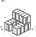
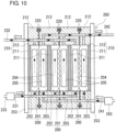
- the RF battery 1 includes a battery container 2 which houses the battery cell 200, the positive and negative electrolyte circulation mechanisms 230 and 240, and the control unit 260, a positive electrolyte tank container 3 which houses the positive electrolyte tank 30, and a negative electrolyte tank container 4 which houses the negative electrolyte tank 40, the three containers 2, 3, and 4 containing different members ( Figs. 1 to 6 , Fig. 9 ). Details will be described below. In Figs. 7 to 11 , black arrows indicate flow of electrolytes.
- the battery container 2 houses the battery cell 200, the positive and negative electrolyte circulation mechanisms 230 and 240, and the control unit 260. Details of the members housed inside the battery container 2 will be described later.
- the positive electrolyte tank container 3 houses the positive electrolyte tank 30, and the negative electrolyte tank container 4 houses the negative electrolyte tank 40.
- the battery container 2, the positive electrolyte tank container 3, and the negative electrolyte tank container 4 contain different members. Therefore, changes in design of battery capacity, battery output, and the like can be easily made. The reason for this is that the battery cell 200 and others, the positive electrolyte tank 30, and the negative electrolyte tank 40 are housed in different containers.
- the battery capacity and battery output of the RF battery 1 can be changed.
- the containers themselves can be exchanged easily, and members (the battery cell 200 and the positive and negative electrolyte tanks 30 and 40) requiring changes in design can be exchanged by exchanging the containers themselves that house the corresponding members.
- each of the containers 2, 3, and 4 is typically a dry container.
- the shape of each of the containers 2, 3, and 4 is typically rectangular parallelepiped.
- the containers 2, 3, and 4 each include a rectangular bottom which is installed on an intended installation place, a rectangular top which is arranged so as to face the bottom, two side walls which connect the long sides of the bottom to the long sides of the top, and two end walls which connect the short sides of the bottom to the short sides of and the top.
- the side walls and the end walls are provided with openable/closable doors so that the worker can access the inside of the container (not shown).
- the containers 2, 3, and 4 are each, for example, made of steel (such as rolled general structural steel SS400).
- each of the containers 2, 3, and 4 can be appropriately selected depending on the battery capacity, battery output, or the like of the RF battery 1. For example, in the case of a large- (small-) capacity RF battery 1, large (small) tank containers 3 and 4 may be selected, and in the case of a high (low) output RF battery 1, a large (small) battery container 2 may be selected. In such a manner, the amounts of positive and negative electrolytes and the number of battery cells that can be housed in the containers 2, 3, and 4 can be increased (decreased).
- An ocean freight container in accordance with ISO standards e.g., ISO 1496-1:2013 is usable as each of the containers 2, 3, and 4.
- Typical examples of the container that can be used as each of the containers 2, 3, and 4 include a 20 ft container, a 40 ft container, and a 45 ft container, and also include taller containers, such as a 20 ft high cube container, a 40 ft high cube container, and a 45 ft high cube container.
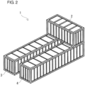
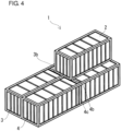
- the three containers 2, 3, and 4 may have the same size. Furthermore, as shown in Figs. 2 , 4 , and 6 , the battery container 2 and the two tank containers 3 and 4 may have different sizes by increasing the size of the two tank containers 3 and 4 compared with the size of the two containers 3 and 4 shown in Figs. 1 , 3 , and 5 . In the case where the battery container 2 and the two tank containers 3 and 4 have different sizes, as shown in Figs. 2 , 4 , and 6 , as the battery container 2, a container smaller than the two tank containers 3 and 4 can be used.
- the total surface area Sb can be determined from the formula "the total surface area Sa - the contact area A". Therefore, the surface area reduction rate Sc (%) determined by the formula " ⁇ 1 - (total surface area Sb)/(total surface area Sa) ⁇ ⁇ 100" can be easily increased. Thereby, it is possible to reduce the volume of a heat insulating material that is used to cover exposed portions of the outer peripheries of the tank containers 3 and 4 in order to suppress changes in temperature of electrolytes due to the external environment, and the operation of covering with the heat insulating material can be simplified, resulting in reduction in costs.
- the three containers 2, 3, and 4 are stacked, so that the containers are stacked in two levels, two tank containers 3 and 4 are arranged on the lower side, and a battery container 2 is placed on the upper side so as to overlap with the roof of at least one of the positive electrolyte tank container 3 and the negative electrolyte tank container 4.
- the tank containers 3 and 4 which are relatively heavy on the lower side and placing the battery container 2 which is relatively light thereon the center of gravity is lower compared with the case where the containers are stacked by reversing the upper and lower containers. Therefore, the RF battery 1 can be stably installed even when the containers 2, 3, and 4 are stacked.
- deformation of the containers (tank containers 3 and 4) on the lower side can be suppressed.
- the battery container 2 on the upper side extends over and between the positive electrolyte tank container 3 and the negative electrolyte tank container 4 on the lower side and is placed evenly on the roofs of the positive electrolyte tank container 3 and the negative electrolyte tank container 4.
- the expression "being placed evenly on” means that when the RF battery 1 is viewed from the top, the overlapping area between the battery container 2 and the positive electrolyte tank container 3 is substantially the same as the overlapping area between the battery container 2 and the negative electrolyte tank container 4. Thereby, the battery container 2 can be stably placed on the roofs of the two tank containers 3 and 4.
- the way of stacking the containers 2, 3, and 4 can be appropriately selected depending on the installation place and the like of the RF battery 1, and examples thereof include cross-stacking type ( Figs. 1 and 2 ).
- the parallel-stacking type ( Figs. 3 and 4 ), and collinear-stacking type ( Figs. 5 and 6 ) are described herein but are not according to the present invention.
- two tank containers 3 and 4 are arranged in parallel left to right such that the longitudinal directions thereof are parallel to each other, and a battery container 2 is placed on the roofs of the two tank containers 3 and 4 such that the longitudinal direction of the battery container 2 crosses (orthogonally, in this example) with the longitudinal directions of the tank containers 3 and 4.
- the cross-stacking type since the contact area A among the three containers is easily increased compared with the non-stacking type, the total surface area Sb is easily decreased, and the surface area reduction rate Sc is easily increased.
- the side surfaces of the two tank containers 3 and 4 face each other.
- the two tank containers 3 and 4 on the lower side are arranged with a predetermined distance between the side surfaces that face each other.
- the predetermined distance is, for example, a distance at which the battery container 2 placed on the roofs of the two tank containers 3 and 4 does not protrude outward in the parallel direction of the two tank containers 3 and 4.
- the distance is preferably set such that the short sides of the battery container 2 overlap with the outer long sides of the tank containers 3 and 4 in the parallel direction.
- a region surrounded by outlines of the two tank containers 3 and 4 can be substantially expressed by the formula "(length in the longitudinal direction of the battery container 2) ⁇ (length in the longitudinal direction of the two tank containers 3 and 4)".
- the installation area of the RF battery 1 can be decreased.
- a portion (central portion in the longitudinal direction) of the bottom of the battery container 2 cannot be stacked on the roofs of the tank containers 3 and 4
- four corners of the battery container 2 can be placed on the roofs of the tank containers 3 and 4.
- corners of a container have high strength. Therefore, since the four corners of the battery container 2 can be placed on the roofs of the two tank containers 3 and 4, the battery container 2 can be stably placed on the roofs of the two tank containers 3 and 4.
- the placing positions of the battery container 2 on the roofs of the two containers 3 and 4 are the centers in the longitudinal direction of the tank containers 3 and 4.
- the placing positions of the battery container 2 are preferably on the one end wall side in the longitudinal direction of the tank containers 3 and 4 (on the back side of the sheet in Figs. 1 and 2 ) as shown in Fig. 1 ( Fig. 2 ). That is, the battery container 2 is placed so as to be close to the one end side in the longitudinal direction of the tank containers 3 and 4.
- arrangement is made such that a long side of the battery container 2 overlaps with the short sides of the two tank containers 3 and 4.
- the short sides of the battery container 2 overlap with the outer long sides in the parallel direction of the tank containers 3 and 4.
- two out of four corners of the battery container 2 each can overlap with a corner of the tank container 3 or 4. Consequently, the battery container 2 can be stably placed on the roofs of the two tank containers 3 and 4.
- the worker can easily access the inside of the battery container 2 from one side surface of the battery container 2 (from the front side of the sheet in Figs. 1 and 2 ), and maintenance of the inside of the battery container 2 can be easily performed.
- the reason for this is that since the battery container 2 is placed so as to be close to the one end side in the longitudinal direction of the two tank containers 3 and 4 (on the back side of the sheet in Figs. 1 and 2 ), it is possible to secure wide space for the worker to be placed on the roofs of the two tank containers 3 and 4 on the other end side in the longitudinal direction.
- a work floor that bridges between the two tank containers 3 and 4 is arranged so that the worker can easily work.
- a platform (bench) with a predetermined height may be temporarily provided on the other side surface side of the battery container 2.
- reinforcing pillars are provided at positions overlapping with the short sides of the battery container 2 in the tank containers 3 and 4, and in particular, at positions overlapping with the corners of the battery container 2 in the tank containers 3 and 4. The reason for this is that the strength of the centers in the longitudinal direction of the tank containers 3 and 4 is not as high as the strength of the corners thereof.
- a heat insulating material (not shown).
- two tank containers 3 and 4 are arranged in parallel such that the longitudinal directions thereof are parallel to each other, and a battery container 2 is placed on the roofs of the two tank containers 3 and 4 such that the longitudinal direction of the battery container 2 is parallel to the longitudinal directions of the two tank containers 3 and 4 (stacked into a so-called heaped bale structure).
- a battery container 2 is placed on the roofs of the two tank containers 3 and 4 such that the longitudinal direction of the battery container 2 is parallel to the longitudinal directions of the two tank containers 3 and 4 (stacked into a so-called heaped bale structure).
- the two tank containers 3 and 4 on the lower side are preferably arranged such that the side surfaces thereof are in contact with each other over the substantially entire region, substantially without a distance between the facing side surfaces.
- the installation area of the RF battery 1 can be further decreased compared with the cross-stacking type.
- the contact area A among the three containers 2, 3, and 4 can be increased compared with the cross-stacking type in which the two tank containers 3 and 4 are arranged with a distance therebetween.
- the contact area A among the three containers 2, 3, and 4 can be increased compared with the cross-stacking type in which the bottom of the battery container 2 is only partially brought into contact with the two tank containers 3 and 4.
- the battery container 2 can be stably placed.
- the worker can access the inside of the battery container 2 from both side surfaces thereof, unlike the cross-stacking type, a platform may not be temporarily provided.
- the placing positions of the battery container 2 on the roofs of the two containers 3 and 4 are preferably on the one end wall side in the longitudinal direction of the tank containers 3 and 4 (on the back side of the sheet in Fig. 4 ), as in the cross-stacking type.
- the RF battery 1 is viewed from the top, arrangement is made such that one short side of the battery container 2 overlaps with the short sides of the two tank containers 3 and 4.
- reinforcing beams 3b and 4b for reinforcing tops are provided at positions overlapping with the other short side of the battery container 2 on the tops of the tank containers 3 and 4.
- reinforcing pillars are provided at positions corresponding to the other short side of the battery container 2 at the side walls of the tank containers 3 and 4 (on the same plane as the reinforcing beams 3b and 4b).
- reinforcing beams are provided on the tops of the tank containers 3 and 4 at positions overlapping with the short sides of the battery container 2.
- reinforcing pillars are provided on the side walls of the tank containers 3 and 4 at positions corresponding to the short sides of the battery container 2.
- two tank containers 3 and 4 are arranged in series such that the longitudinal directions thereof are collinear with each other, and a battery container 2 is placed on the roofs of the two tank containers 3 and 4 such that the longitudinal direction of the battery container 2 is collinear with the longitudinal directions of the two tank containers 3 and 4.
- the contact area A among the three containers can be increased compared with the cross-stacking type, the total surface area Sb is easily decreased, and the surface area reduction rate Sc is easily increased.
- the end surfaces of the two tank containers 3 and 4 face each other.
- the longitudinal directions of the three containers 2, 3, and 4 are all collinear.
- the two tank containers 3 and 4 on the lower side are preferably arranged such that the end surfaces thereof are in contact with each other over the substantially entire region, substantially without a distance between the end surfaces of the tank containers 3 and 4, as in the parallel-stacking type. Thereby, as in the parallel-stacking type, the installation area of the RF battery 1 can be decreased.
- the end surfaces of the two tank containers 3 and 4 are brought into contact with each other, and also the substantially entire region of the bottom of the battery container 2 can be brought into contact with the two tank containers 3 and 4.
- the contact area A among the three containers 2, 3, and 4 can be increased compared with the cross-stacking type in which the two tank containers 3 and 4 are arranged with a distance therebetween and the bottom of the battery container 2 is only partially brought into contact the tank container 3 and 4.
- the battery container 2 since the substantially entire region of the bottom of the battery container 2 is stacked on the roofs of the two tank containers 3 and 4, the battery container 2 can be stably placed. Since it is possible to reduce space between the facing end surfaces of the two tank containers 3 and 4, a heat insulating material may not be arranged on the facing end surfaces. In the case where the worker accesses the inside of the battery container 2 from both side surfaces thereof, platforms may be temporarily provided.
- the RF battery 1 includes positive and negative electrolyte circulation passages configured to circulate positive and negative electrolytes between the battery container 2 and the tank container 3 and between the battery container 2 and the tank container 4.
- the positive and negative electrolyte circulation passages respectively include, as shown in Figs. 7 and 8 (appropriately, Figs. 9 and 10 ), positive and negative electrolyte supply pipes 231 and 241, positive and negative electrolyte discharge pipes 232 and 242, positive and negative electrolyte outgoing pipes 31 and 41, positive and negative electrolyte return pipes 32 and 42, and connection structures 5.
- through-holes for inserting the circulation passages are formed in a bottom plate 2b constituting the bottom of the battery container 2 and top plates 3u and 4u constituting the tops of the tank containers 3 and 4 at positions overlapping with each other, and through-holes are formed in top plates 30u and 40u constituting the tops of the positive and negative electrolyte tanks 30 and 40 at positions corresponding to the overlapping positions.
- the through-holes overlap with each other so as to face each other ( Figs. 7 and 8 ).
- the positive and negative electrolyte supply pipes 231 and 241 supply the positive and negative electrolytes to positive and negative electrode cells 202 and 203, respectively, and the positive and negative electrolyte discharge pipes 232 and 242 discharge the positive and negative electrolytes from the positive and negative electrode cells 202 and 203, respectively.
- the positive and negative electrolyte supply pipes 231 and 241 and the positive and negative electrolyte discharge pipes 232 and 242 are arranged inside the battery container 2 in this example.
- the positive and negative electrolyte supply pipes 231 and 241 are connected at one end to the positive and negative electrolyte outgoing pipes 31 and 41, respectively, and the positive and negative electrolyte supply pipes 231 and 241 are connected at the other end to the positive and negative electrode cells 202 and 203, respectively.
- the positive and negative electrolyte discharge pipes 232 and 242 are connected at one end to the positive and negative electrode cells 202 and 203, respectively, and the positive and negative electrolyte discharge pipes 232 and 242 are connected at the other end to the positive and negative electrolyte return pipes 32 and 42, respectively.
- the positive and negative electrolyte outgoing pipes 31 and 41 send the positive and negative electrolytes to the positive and negative electrolyte supply pipes 231 and 241, respectively, and the positive and negative electrolyte return pipes 32 and 42 return the positive and negative electrolytes from the positive and negative electrolyte discharge pipes 232 and 242 to the positive and negative electrolyte tanks 30 and 40, respectively.
- the positive and negative electrolyte outgoing pipes 31 and 41 and the positive and negative electrolyte return pipes 32 and 42 are provided so as to extend from the inside of the positive and negative electrolyte tanks 30 and 40 and protrude toward the outside of the tank containers 3 and 4, and pass through the through-holes to reach the inside of the battery container 2.
- An intervening member e.g., a rubber nozzle
- the positive and negative electrolyte outgoing pipes 31 and 41 and the positive and negative electrolyte return pipes 32 and 42 are fixed on the top plates 3u and 4u of the tank containers 3 and 4, respectively, in order to prevent positional shift in the longitudinal direction.
- One end portion of each of the positive and negative electrolyte outgoing pipes 31 and 41 is open to the corresponding positive or negative electrolyte inside the positive or negative electrolyte tank 30 or 40.
- the position in the height direction of the one end portion of each of the positive and negative electrolyte outgoing pipes 31 and 41 is set to be below the lowest liquid level (not shown) of the corresponding electrolyte tank 30 or 40.
- the other end portion of each of the electrolyte outgoing pipes 31 and 41 is connected to the corresponding electrolyte supply pipe 231 or 241 inside the battery container 2.
- connection structures 5 connect the positive and negative electrolyte supply pipes 231 and 241 and the positive and negative electrolyte discharge pipes 232 and 242 to the positive and negative electrolyte outgoing pipes 31 and 41 and the positive and negative electrolyte return pipes 32 and 42, respectively.
- the arrangement positions of the connection structures 5 between the pipe 231 and the outgoing pipe 31 and between the pipe 232 and the return pipe 32 on the positive electrode side and the arrangement positions of the connection structures 5 between the pipe 241 and the outgoing pipe 41 and between the pipe 242 and the return pipe 42 on the negative electrode side are inside the battery container 2 as described above in this example, but are not particularly limited, and can be appropriately selected as shown in modification examples which will be described later.
- connection structures 5 on the positive and negative electrode sides (connection of the positive and negative electrolyte outgoing pipes 31 and 41 to the positive and negative electrolyte supply pipes 231 and 241, respectively, and connection of the positive and negative electrolyte return pipes 32 and 42 to the positive and negative electrolyte discharge pipes 232 and 242, respectively) are preferably detachable. Thereby, changes in design of battery capacity, battery output, and the like can be easily made. The reason for this is that when the containers themselves are exchanged due to occurrence of changes in design of battery capacity, battery output, and the like, the pipes can be easily detached. Usually, electrolyte flow pipes are connected to each other by using fusion bonding or the like so as not to be detached from each other. Thus, once the pipes are connected to each other, the disassembly operation is likely to be very complicated.
- connection structures 5 on the positive and negative electrode sides are preferably capable of expanding and contracting.
- the pipes are easily aligned, and therefore, the operation of connecting the pipes can be easily performed.
- flexible joints may be used for the connection structures 5 on the positive and negative electrode sides.
- valves 6 for opening and closing the positive or negative electrolyte circulation passage are interposed between the connection structures 5 (flexible joints) and the positive and negative electrolyte supply pipes 231 and 241 and between the connection structures 5 (flexible joints) and the positive and negative electrolyte discharge pipes 232 and 242.
- the type of valves 6 can be appropriately selected, and examples thereof include butterfly valves, gate valves, globe valves, ball valves, and diaphragm valves.
- the sub-stack 251 is formed by stacking a cell frame 210 having a bipolar plate 211 and a frame body 212 surrounding the outer periphery thereof, a positive electrode 204, a membrane 201, and a negative electrode 205 in this order repeatedly, and supply/drainage plates 252 (the view of the lower part of Fig. 11 ; omitted in Fig. 10 ) are disposed on both ends of the layered body.
- a battery cell 200 is formed between bipolar plates 211 of two adjacent cell frames 210.
- the positive electrolyte circulation mechanism 230 and the negative electrolyte circulation mechanism 240 include a positive electrolyte supply pipe 231 and a negative electrolyte supply pipe 241, a positive electrolyte discharge pipe 232 and a negative electrolyte discharge pipe 242, and a positive electrolyte pump 233 and a negative electrolyte pump 243, respectively ( Fig. 9 ).
- the positive and negative electrolyte supply pipes 231 and 241 and the positive and negative electrolyte discharge pipes 232 and 242 are as described above.
- the positive and negative electrolyte pumps 233 and 243 are stopped so that the positive and negative electrolytes are not circulated.
- the positive and negative electrolyte pumps 233 and 243 any type can be appropriately selected, and for example, self-suction pumps can be used.
- the positive and negative electrolyte pumps 233 and 243 are provided in the middle of the positive and negative electrolyte supply pipes 231 and 241, respectively, in this example.
- the positive electrolyte pump 233 and the negative electrolyte pump 243 are arranged at positions that are symmetrical with respect to the center in the longitudinal direction of the battery container 2. Thereby, it is possible to suppress deviation of the center of gravity of the battery container 2.
- the battery container 2 can further house a control unit 260, a heat exchanger 270, and the like.
- the control unit 260 controls circulation of the positive and negative electrolytes in the positive electrolyte circulation mechanism 230 and the negative electrolyte circulation mechanism 240, respectively.
- the control unit 260 specifically, includes a pump control unit which controls the positive and negative electrolyte pumps provided in the positive and negative electrolyte circulation mechanisms.
- the control unit 260 for example, a computer or the like can be used.
- the control unit 260 may be arranged outside the three containers 2 to 4.
- the heat exchanger 270 cools the positive and negative electrolytes.
- the positive and negative electrolytes may be cooled by spontaneous cooling or forced cooling with a cooling mechanism, such as a fan, provided separately (not shown).
- a cooling mechanism such as a fan
- the number of heat exchangers 270 is plural (two), and the positive and negative electrolytes are individually cooled.
- the arrangement positions of the heat exchangers 270 are in the middle of the positive and negative electrolyte discharge pipes 232 and 242 in this example, but may be in the middle of the positive and negative electrolyte supply pipes 231 and 241.
- the positive and negative electrolytes generate heat as a result of battery reactions.
- the positive and negative electrolytes can be satisfactorily cooled.
- the heat exchanger 270 for cooling the positive electrolyte and the heat exchanger 270 for cooling the negative electrolyte are preferably arranged at positions that are symmetrical with respect to the center in the longitudinal direction of the battery container 2. Thereby, it is possible to suppress deviation of the center of gravity of the battery container 2.
- the positive electrolyte tank container 3 and the negative electrolyte tank container 4 house a positive electrolyte tank 30 and a negative electrolyte tank 40, a positive electrolyte outgoing pipe 31 and a negative electrolyte outgoing pipe 41, and a positive electrolyte return pipe 32 and a negative electrolyte return pipe 42, respectively.
- the positive and negative electrolyte outgoing pipes 31 and 41 and the positive and negative electrolyte return pipes 32 and 42 are as described above.
- the positive and negative electrolyte tanks 30 and 40 are each a box-like case, whose shape is the same as the tank containers 3 and 4 and is rectangular parallelepiped in this example.
- the size of the positive and negative electrolyte tanks 30 and 40 is slightly smaller than that of the tank containers 3 and 4.
- the same resins and rubber as those used for the coating layer of the positive electrolyte supply pipe 231 and the like may be used.
- connection of the positive and negative electrolyte outgoing pipes 31 and 41 and the positive and negative electrolyte return pipes 32 and 42 to the electrolyte tanks 30 and 40 is performed by the intervening member which fills the space between each of the positive and negative electrolyte outgoing pipes 31 and 41 and the positive and negative electrolyte return pipes 32 and 42 and the corresponding through-hole in the positive or negative electrolyte tank 30 or 40.
- the intervening members are mounted on the positive and negative electrolyte outgoing pipes 31 and 41 and the positive and negative electrolyte return pipes 32 and 42 so as to avoid positional shift in the longitudinal direction of the positive and negative electrolyte outgoing pipes 31 and 41 and the positive and negative electrolyte return pipes 32 and 42.
- the positive and negative electrolyte tank containers 3 and 4 can further house gas phase communicating tubes (a positive electrode gas phase insertion tube and a negative electrode gas phase insertion tube) which connect the gas phase inside the positive electrolyte tank 30 and the gas phase inside the negative electrolyte tank 40 to each other, and a pressure adjustment mechanism for adjusting the pressure of the gas phase inside each of the positive and negative electrolyte tanks 30 and 40 (both not shown).
- gas phase communicating tubes a positive electrode gas phase insertion tube and a negative electrode gas phase insertion tube
- One end of the positive electrode gas phase insertion tube is open to the gas phase inside the positive electrolyte tank 30, and one end of the negative electrode gas phase insertion tube is open to the gas phase inside the negative electrolyte tank 40.
- the other end of the positive electrode gas phase insertion tube and the other end of the negative electrode gas phase insertion tube are connected to each other inside one of the tank containers or outside the two tank containers 3 and 4.
- a detachable connection structure as in the connection structure 5 described above, or a connection structure capable of expanding and contracting can be used.
- the pressure adjustment mechanism a known pressure adjustment bag that expands or contracts in response to changes in the pressure of the gas phase inside each of the positive and negative electrolyte tanks 30 and 40 can be used.
- the pressure adjustment mechanism may be provided either inside or outside each of the positive and negative electrolyte tanks 30 and 40.
- Changes in design of the RF battery 1 can be made, for example, as described below.
- the tank containers 3 and 4 can be used directly without being moved.
- the subsequent connection of the pipes is performed in the same manner as in the case of changing the battery capacity.
- the battery output can be increased by increasing the number of battery containers 2 without changing the size of the battery container 2.
- the battery output can also be increased by constituting a battery module including the three containers 2, 3, and 4, and increasing the number of battery modules (installing more battery modules).
- the battery cell 200 and others, the positive electrolyte tank 30, and the negative electrolyte tank 40 are housed in the different containers 2, 3, and 4.
- the containers themselves can be exchanged easily, and members (the battery cell 200 and the positive and negative electrolyte tanks 30 and 40) requiring changes in design can be exchanged by exchanging the containers 2, 3, and 4 themselves housing the corresponding members.
- the tank containers 3 and 4 and the battery container 2 themselves are exchanged for containers 2, 3, and 4 having different sizes, the amounts of electrolytes and the number of battery cells housed inside can be changed, and the battery capacity and battery output of the RF battery 1 can be changed.
- the positive electrolyte outgoing pipe 31 extends from the inside of the positive electrolyte tank container 3 through the through-hole of the positive electrolyte tank container 3 toward the outside of the positive electrolyte tank container 3 and is connected to a connection structure 5.
- the positive electrolyte supply pipe 231 extends from the connection structure 5, passes through the through-hole of the battery container 2, and is led into the battery container 2.
- the positive electrolyte discharge pipe 232 extends from the battery container 2 through the through-hole of the battery container 2 toward the outside of the battery container 2 and is connected to a connection structure 5.
- connection structure 5 extends from the connection structure 5, passes through the through-hole of the positive electrolyte tank container 3, and is led into the positive electrolyte tank container 3.
- the arrangement positions of the connection structures 5 can be, as shown in Fig. 12 , outside the end plate or side plate of the battery container 2 (outside the side plate or end plate of the positive electrolyte tank container 3), or can be, as shown in Fig. 13 , outside the side plate or end plate of the battery container 2 and above the top plate of the top plate 3u of the positive electrolyte tank container 3.
- connection structure 5 between the pipe 231 and the outgoing pipe 31 and the connection structure 5 between the pipe 232 and the return pipe 32 on the positive electrode side may be arranged inside one of the battery container 2 and the positive electrolyte tank container 3, and the other connection structure 5 may be arranged outside the three containers 2 to 4.
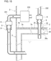
- connection structures 5 may be arranged, for example, inside the battery container 2 as shown in Figs. 14 and 15 , or may be arranged inside the positive electrolyte tank container 3, although not shown.
- One of the connection structures 5 may be a connection structure 5 which connects the positive electrolyte supply pipe 231 to the positive electrolyte outgoing pipe 31 as shown in Fig. 14 , or may be a connection structure 5 which connects the positive electrolyte discharge pipe 232 to the positive electrolyte return pipe 32 as shown in Fig. 15 .
- the positive electrolyte outgoing pipe 31 and the positive electrolyte supply pipe 231 are as described above with reference to Fig. 12 .
- the positive electrolyte discharge pipe 232 and the positive electrolyte return pipe 32 are as described in the embodiment with reference to Fig. 7 . That is, the positive electrolyte discharge pipe 232 is arranged inside the battery container 2 and is connected to the connection structure 5.
- the positive electrolyte return pipe 32 extends from the connection structure 5, passes through the through-holes of the battery container 2 and the positive electrolyte tank container 3, and is led into the positive electrolyte tank container 3.
- connection structure 5 between the positive electrolyte supply pipe 231 (positive electrolyte discharge pipe 232) and the positive electrolyte outgoing pipe 31 (positive electrolyte return pipe 32) can be inside the battery container 2 as shown in Fig. 14 ( Fig. 15 ), and the arrangement position of the connection structure 5 between the positive electrolyte return pipe 32 (positive electrolyte outgoing pipe 31) and the positive electrolyte discharge pipe 232 (positive electrolyte supply pipe 231) can be outside the end plate or side plate of the battery container 2 (outside the side plate or end plate of the positive electrolyte tank container 3).
- connection structure 5 between the pipe 231 and the outgoing pipe 31 and the connection structure 5 between the pipe 232 and the return pipe 32 on the positive electrode side may be arranged inside the battery container 2, and the other connection structure 5 may be arranged inside the positive electrolyte tank container 3, although not shown.
- the number of battery modules was set to be one for each calculation object.
- the contact area A among the containers, the total surface area Sb, and the surface area reduction rate Sc were calculated for each of the cross-stacking type, parallel-stacking type, and collinear-stacking type arrangements.
- three containers were combined in seven patterns (P1 to P7) described below.
- the containers were stacked in two levels. Two tank containers were arranged on the lower side, and one battery container was placed on the upper side so as to extend over and between the two tank containers on the lower side, evenly on the roofs of the two tank containers.
- the total surface area Sb was determined from the formula "the total surface area Sa of the non-stacking type - the contact area A".
- the surface area reduction rate Sc (%) was determined by the formula " ⁇ 1 - (total surface area Sb)/(total surface area Sa) ⁇ ⁇ 100". The calculation results thereof are shown in Table 1.
- P1 Three containers are all 20 ft containers.
- a battery container is a 20 ft container, and two tank containers are 40 ft containers.
- a battery container is a 20 ft high cube container, and two tank containers are 40 ft high cube containers.
- P5 Three containers are all 40 ft containers.
- P6 Three containers are all 40 ft high cube containers.
- a battery container is a 20 ft high cube container, and two tank containers are 45 ft high cube containers.
- the contact area A is larger than the contact area of the non-stacking type. This is because the contact area of the non-stacking type is 0 (zero). Therefore, in each of the cross-stacking type, the parallel-stacking type, and the collinear-stacking type, even if the combination of the three containers is in any of the patterns P1 to P7, the total surface area Sb is smaller than the total surface area Sa of the non-stacking type.
- the surface area reduction rate Sc of each of the cross-stacking type, the parallel-stacking type, and the collinear-stacking type can be increased, even if the combination of the three containers is in any of the patterns P1 to P7.
- the surface area reduction rate Sc can be 5% or more.
- the contact area A can be increased compared with the cross-stacking type, and therefore, the total surface area Sb can be decreased to increase the surface area reduction rate Sc.
- the number of battery modules was varied in the range of 2 to 20.
- the contact area A among the containers, the total surface area Sb, and the surface area reduction rate Sc were calculated for each of cross-stacking type, parallel-stacking type, and collinear-stacking type battery modules.
- two patterns, i.e., patterns P2 and P4 in Calculation Example 1 were set for each type.
- the calculation results in the case where three containers were combined in pattern P2 in each battery module are shown in Table 2, and the calculation results in the case of P4 are shown in Table 3.
- the battery modules are arranged in the parallel direction of the tank containers. Specifically, the longitudinal directions of the battery containers are collinear with each other, and the end surfaces of the battery containers of the adjacent battery modules are in contact with each other over the substantially entire region. The side surfaces of the tank containers of the adjacent battery modules are in contact with each other over the substantially entire region.
- the battery modules are arranged in the parallel direction of the tank containers. Specifically, the side surfaces of the tank containers of the adjacent battery modules are in contact with each other over the substantially entire region. The side surfaces of the battery containers of the adjacent battery modules face each other over the substantially entire region, but with a distance therebetween without being in contact with each other.
- the total surface area Sb is smaller than the total surface area Sa of the non-stacking type.
- the surface area reduction rate Sc is large.
- the surface area reduction rate Sc increases as the number of battery modules is increased. As the number of battery modules is increased, the contact area A can be increased, the total surface area Sb can be decreased, and the surface area reduction rate Sc can be increased. Although depending on the stacking type and the number of battery modules, the surface area reduction rate Sc can be 50% or more.
Landscapes
- Life Sciences & Earth Sciences (AREA)
- Engineering & Computer Science (AREA)
- Manufacturing & Machinery (AREA)
- Sustainable Development (AREA)
- Sustainable Energy (AREA)
- Chemical & Material Sciences (AREA)
- Chemical Kinetics & Catalysis (AREA)
- Electrochemistry (AREA)
- General Chemical & Material Sciences (AREA)
- Fuel Cell (AREA)
- Inert Electrodes (AREA)
Claims (3)
- Redox-Flow-Batterie (1), umfassend:einen Tankbehälter (3) für einen positiven Elektrolyten, der einen Tank (30) für einen positiven Elektrolyten zur Speicherung eines positiven Elektrolyten enthält;einen Tankbehälter (4) für einen negativen Elektrolyten, der einen Tank (40) für einen negativen Elektrolyten zur Speicherung eines negativen Elektrolyten enthält; undeinen Batteriebehälter (2), der eine Batteriezelle (200), umfassend eine positive Elektrode (204), eine negative Elektrode (205) und eine Membran (201), einen Mechanismus (230) zum Umwälzen von einem positiven Elektrolyten, ausgebildet zum Zuführen und Umwälzen des positiven Elektrolyten zur Batteriezelle (200), und einen Mechanismus (240) zum Umwälzen von einem negativen Elektrolyten, ausgebildet zum Zuführen und Umwälzen des negativen Elektrolyten zur Batteriezelle (200), enthält,wobei der Batteriebehälter (2) auf dem Dach des Tankbehälters (3) für einen positiven Elektrolyten oder/und des Tankbehälters (4) für einen negativen Elektrolyten angeordnet ist,dadurch gekennzeichnet, dass:sich der Batteriebehälter (2) über und zwischen dem Tankbehälter (3) für einen positiven Elektrolyten und dem Tankbehälter (4) für einen negativen Elektrolyten erstreckt und gleichmäßig auf den Dächern des Tankbehälters (3) für einen positiven Elektrolyten und des Tankbehälters (4) für einen negativen Elektrolyten angeordnet ist,bei Betrachtung der Redox-Flow-Batterie (1) von oben die Überlappungsfläche zwischen dem Batteriebehälter (2) und dem Tankbehälter (3) für einen positiven Elektrolyten im Wesentlichen die gleiche ist wie die Überlappungsfläche zwischen dem Batteriebehälter (2) und dem Tankbehälter (4) für einen negativen Elektrolyten,der Tankbehälter (3) für einen positiven Elektrolyten und der Tankbehälter (4) für einen negativen Elektrolyten parallel mit einem Abstand dazwischen angeordnet sind, so dass ihre Längsrichtungen parallel zueinander sind,der Batteriebehälter (2) so angeordnet ist, dass seine Längsrichtung orthogonal zu den Längsrichtungen des Tankbehälters (3) für einen positiven Elektrolyten und des Tankbehälters (4) für einen negativen Elektrolyten ist, unddie Anordnungspositionen des Batteriebehälters (2) die Mitten in der Längsrichtung des Tankbehälters (3) für einen positiven Elektrolyten und des Tankbehälters (4) für einen negativen Elektrolyten sind und Verstärkungspfeiler an Positionen vorgesehen sind, die mit den Ecken des Batteriebehälters (2) im positiven Tankbehälter (3) für einen positiven Elektrolyten und im Tankbehälter (4) für einen negativen Elektrolyten überlappen.
- Redox-Flow-Batterie (1) nach Anspruch 1,wobei der Mechanismus (230) zum Umwälzen des positiven Elektrolyten ein Zuführrohr (231) für den positiven Elektrolyten zum Zuführen des positiven Elektrolyten zur Batteriezelle (200) und ein Auslaufrohr (232) für den positiven Elektrolyten zum Auslaufen des positiven Elektrolyten aus der Batteriezelle (200) umfasst und der Mechanismus (240) zum Umwälzen des negativen Elektrolyten ein Zuführrohr (241) für den negativen Elektrolyten zum Zuführen des negativen Elektrolyten zur Batteriezelle (200) und ein Auslaufrohr (242) für den negativen Elektrolyten zum Auslaufen des negativen Elektrolyten aus der Batteriezelle (200) umfasst,wobei der Tank (30) für einen positiven Elektrolyten ein Ausgangsrohr (41) für den positiven Elektrolyten zum Leiten des positiven Elektrolyten vom Tank (30) für einen positiven Elektrolyten zum Zuführrohr (231) für den positiven Elektrolyten und ein Rücklaufrohr (42) für den positiven Elektrolyten zum Rücklaufen des positiven Elektrolyten vom Auslaufrohr (232) für den positiven Elektrolyten zum Tank (30) für einen positiven Elektrolyten umfasst und der Tank (40) für einen negativen Elektrolyten ein Ausgangsrohr für den negativen Elektrolyten zum Leiten des negativen Elektrolyten vom Tank (40) für einen negativen Elektrolyten zum Zuführrohr (241) für den negativen Elektrolyten und ein Rücklaufrohr für den negativen Elektrolyten zum Rücklaufen des negativen Elektrolyten vom Auslaufrohr (242) für den negativen Elektrolyten zum Tank (40) für einen negativen Elektrolyten umfasst, undwobei die Redox-Flow-Batterie (1) ferner Verbindungsstrukturen (5) umfasst, die das Zuführrohr (231) für den positiven Elektrolyten, das Zuführrohr (241) für den negativen Elektrolyten, das Auslaufrohr (232) für den positiven Elektrolyten und das Auslaufrohr (242) für den negativen Elektrolyten jeweils mit dem Auslaufrohr (41) für den positiven Elektrolyten, dem Auslaufrohr für den negativen Elektrolyten, dem Rücklaufrohr (42) für den positiven Elektrolyten und dem Rücklaufrohr für den negativen Elektrolyten lösbar verbinden.
- Redox-Flow-Batterie (1) nach einem der vorhergehenden Ansprüche, wobei der Mechanismus (230) zum Umwälzen des positiven Elektrolyten und der Mechanismus (240) zum Umwälzen des negativen Elektrolyten eine Pumpe (233) für den positiven Elektrolyten und eine Pumpe (243) für den negativen Elektrolyten zum Umwälzen jeweils des positiven Elektrolyten und des negativen Elektrolyten umfassen, und
bei Betrachtung des Inneren des Batteriebehälters (2) in Seitenansicht die Pumpe (233) für den positiven Elektrolyten und die Pumpe (243) für den negativen Elektrolyten an Positionen angeordnet sind, die in Bezug auf die Mitte in Links-Rechts-Richtung des Batteriebehälters (2) symmetrisch sind.
Applications Claiming Priority (1)
| Application Number | Priority Date | Filing Date | Title |
|---|---|---|---|
| PCT/JP2017/039813 WO2019087366A1 (ja) | 2017-11-02 | 2017-11-02 | レドックスフロー電池 |
Publications (3)
| Publication Number | Publication Date |
|---|---|
| EP3706222A1 EP3706222A1 (de) | 2020-09-09 |
| EP3706222A4 EP3706222A4 (de) | 2020-11-18 |
| EP3706222B1 true EP3706222B1 (de) | 2025-03-05 |
Family
ID=66331709
Family Applications (1)
| Application Number | Title | Priority Date | Filing Date |
|---|---|---|---|
| EP17882270.6A Active EP3706222B1 (de) | 2017-11-02 | 2017-11-02 | Redox-flow-batterie |
Country Status (7)
| Country | Link |
|---|---|
| US (1) | US10950879B2 (de) |
| EP (1) | EP3706222B1 (de) |
| JP (1) | JP6948596B2 (de) |
| KR (1) | KR102427531B1 (de) |
| CN (1) | CN109997269B (de) |
| TW (1) | TWI785084B (de) |
| WO (1) | WO2019087366A1 (de) |
Families Citing this family (4)
| Publication number | Priority date | Publication date | Assignee | Title |
|---|---|---|---|---|
| WO2018201081A1 (en) * | 2017-04-28 | 2018-11-01 | Ess Tech, Inc. | Methods and systems for redox flow battery electrolyte hydration |
| JP7017251B2 (ja) * | 2019-07-04 | 2022-02-08 | 株式会社岐阜多田精機 | レドックスフロー電池 |
| WO2025126585A1 (ja) * | 2023-12-15 | 2025-06-19 | 住友電気工業株式会社 | レドックスフロー電池システム |
| JP7761184B1 (ja) * | 2025-03-04 | 2025-10-28 | 株式会社Tmeic | 電気設備システム |
Citations (1)
| Publication number | Priority date | Publication date | Assignee | Title |
|---|---|---|---|---|
| US20120164498A1 (en) * | 2010-12-22 | 2012-06-28 | Jd Holding Inc. | Systems and methods for redox flow battery scalable modular reactant storage |
Family Cites Families (12)
| Publication number | Priority date | Publication date | Assignee | Title |
|---|---|---|---|---|
| JP2638023B2 (ja) * | 1988-01-06 | 1997-08-06 | 株式会社明電舎 | 電解液循環型電池 |
| JPH02114454A (ja) * | 1988-10-24 | 1990-04-26 | Kansai Electric Power Co Inc:The | 電解液循環型二次電池 |
| CA2317452A1 (en) * | 1998-01-28 | 1999-08-05 | Chemieco S.R.L. | Redox flow battery system and cell stack |
| JP2000030729A (ja) * | 1998-07-10 | 2000-01-28 | Sumitomo Electric Ind Ltd | 電解液流通型二次電池 |
| JP2005243326A (ja) | 2004-02-25 | 2005-09-08 | Kansai Electric Power Co Inc:The | ハイブリッド電源システム |
| US7740977B2 (en) * | 2007-03-26 | 2010-06-22 | Jd Holding Inc. | Vanadium redox battery incorporating multiple electrolyte reservoirs |
| JP2012099368A (ja) | 2010-11-02 | 2012-05-24 | Sumitomo Electric Ind Ltd | セルスタック、セルフレーム、レドックスフロー電池、およびセルスタックの製造方法 |
| CN103022542A (zh) * | 2012-12-13 | 2013-04-03 | 朝阳华鼎储能技术有限公司 | 一种液流框装置及含有该装置的钒电池 |
| JP2015032356A (ja) | 2013-07-31 | 2015-02-16 | 富士重工業株式会社 | 蓄電システム、及びこれを有する車両 |
| WO2015029941A1 (ja) | 2013-08-26 | 2015-03-05 | 一般社団法人新エネルギー支援機構 | 電力エネルギーの輸送システム |
| US10333159B2 (en) * | 2014-07-07 | 2019-06-25 | Unienergy Technologies, Llc | Charge capacity management in redox flow battery string |
| GB201511695D0 (en) * | 2015-07-03 | 2015-08-19 | Renewable Energy Dynamics Technology Ltd | Improvements in redox flow batteries |
-
2017
- 2017-11-02 EP EP17882270.6A patent/EP3706222B1/de active Active
- 2017-11-02 KR KR1020187017369A patent/KR102427531B1/ko active Active
- 2017-11-02 US US16/067,190 patent/US10950879B2/en active Active
- 2017-11-02 JP JP2018524501A patent/JP6948596B2/ja active Active
- 2017-11-02 WO PCT/JP2017/039813 patent/WO2019087366A1/ja not_active Ceased
- 2017-11-02 CN CN201780005366.XA patent/CN109997269B/zh active Active
-
2018
- 2018-08-03 TW TW107127068A patent/TWI785084B/zh active
Patent Citations (1)
| Publication number | Priority date | Publication date | Assignee | Title |
|---|---|---|---|---|
| US20120164498A1 (en) * | 2010-12-22 | 2012-06-28 | Jd Holding Inc. | Systems and methods for redox flow battery scalable modular reactant storage |
Also Published As
| Publication number | Publication date |
|---|---|
| TWI785084B (zh) | 2022-12-01 |
| CN109997269B (zh) | 2022-03-01 |
| JP6948596B2 (ja) | 2021-10-13 |
| KR102427531B1 (ko) | 2022-08-01 |
| CN109997269A (zh) | 2019-07-09 |
| US10950879B2 (en) | 2021-03-16 |
| EP3706222A4 (de) | 2020-11-18 |
| JPWO2019087366A1 (ja) | 2020-09-24 |
| KR20200081169A (ko) | 2020-07-07 |
| US20190237781A1 (en) | 2019-08-01 |
| TW201919270A (zh) | 2019-05-16 |
| AU2017378609A1 (en) | 2019-05-16 |
| WO2019087366A1 (ja) | 2019-05-09 |
| EP3706222A1 (de) | 2020-09-09 |
Similar Documents
| Publication | Publication Date | Title |
|---|---|---|
| US12283726B2 (en) | Flow battery system | |
| EP3706222B1 (de) | Redox-flow-batterie | |
| US10622601B2 (en) | Battery module carrier, battery system and use of a modified H-beam as battery module carrier | |
| US20230013678A1 (en) | A thermally controlled housing assembly for electrical cells | |
| CN110073533B (zh) | 氧化还原液流电池 | |
| KR102393561B1 (ko) | 레독스 플로우 전지 | |
| AU2017378609B2 (en) | Redox flow battery | |
| JP6677045B2 (ja) | レドックスフロー電池用枠体、レドックスフロー電池、及びセルスタック | |
| CN224217480U (zh) | 一种集成式储能集装箱及其组件 | |
| JP2000030729A (ja) | 電解液流通型二次電池 | |
| CN121039027A (zh) | 集装箱、储能装置、储能设备、储能系统及充电网络 | |
| CN121666658A (zh) | 储能装置、储能系统、充电网络 | |
| CN121263914A (zh) | 电池箱和包括该电池箱的能量存储系统 |
Legal Events
| Date | Code | Title | Description |
|---|---|---|---|
| STAA | Information on the status of an ep patent application or granted ep patent |
Free format text: STATUS: UNKNOWN |
|
| STAA | Information on the status of an ep patent application or granted ep patent |
Free format text: STATUS: THE INTERNATIONAL PUBLICATION HAS BEEN MADE |
|
| PUAI | Public reference made under article 153(3) epc to a published international application that has entered the european phase |
Free format text: ORIGINAL CODE: 0009012 |
|
| STAA | Information on the status of an ep patent application or granted ep patent |
Free format text: STATUS: REQUEST FOR EXAMINATION WAS MADE |
|
| 17P | Request for examination filed |
Effective date: 20180627 |
|
| AK | Designated contracting states |
Kind code of ref document: A1 Designated state(s): AL AT BE BG CH CY CZ DE DK EE ES FI FR GB GR HR HU IE IS IT LI LT LU LV MC MK MT NL NO PL PT RO RS SE SI SK SM TR |
|
| AX | Request for extension of the european patent |
Extension state: BA ME |
|
| A4 | Supplementary search report drawn up and despatched |
Effective date: 20201015 |
|
| RIC1 | Information provided on ipc code assigned before grant |
Ipc: H01M 8/04082 20160101ALI20201009BHEP Ipc: H01M 8/18 20060101AFI20201009BHEP Ipc: H01M 8/04186 20160101ALI20201009BHEP Ipc: H01M 8/0258 20160101ALI20201009BHEP |
|
| DAV | Request for validation of the european patent (deleted) | ||
| DAX | Request for extension of the european patent (deleted) | ||
| STAA | Information on the status of an ep patent application or granted ep patent |
Free format text: STATUS: EXAMINATION IS IN PROGRESS |
|
| 17Q | First examination report despatched |
Effective date: 20240429 |
|
| GRAP | Despatch of communication of intention to grant a patent |
Free format text: ORIGINAL CODE: EPIDOSNIGR1 |
|
| STAA | Information on the status of an ep patent application or granted ep patent |
Free format text: STATUS: GRANT OF PATENT IS INTENDED |
|
| INTG | Intention to grant announced |
Effective date: 20241125 |
|
| P01 | Opt-out of the competence of the unified patent court (upc) registered |
Free format text: CASE NUMBER: APP_65003/2024 Effective date: 20241209 |
|
| GRAS | Grant fee paid |
Free format text: ORIGINAL CODE: EPIDOSNIGR3 |
|
| GRAA | (expected) grant |
Free format text: ORIGINAL CODE: 0009210 |
|
| STAA | Information on the status of an ep patent application or granted ep patent |
Free format text: STATUS: THE PATENT HAS BEEN GRANTED |
|
| AK | Designated contracting states |
Kind code of ref document: B1 Designated state(s): AL AT BE BG CH CY CZ DE DK EE ES FI FR GB GR HR HU IE IS IT LI LT LU LV MC MK MT NL NO PL PT RO RS SE SI SK SM TR |
|
| REG | Reference to a national code |
Ref country code: GB Ref legal event code: FG4D |
|
| REG | Reference to a national code |
Ref country code: CH Ref legal event code: EP |
|
| REG | Reference to a national code |
Ref country code: DE Ref legal event code: R096 Ref document number: 602017088217 Country of ref document: DE |
|
| REG | Reference to a national code |
Ref country code: IE Ref legal event code: FG4D |
|
| PG25 | Lapsed in a contracting state [announced via postgrant information from national office to epo] |
Ref country code: RS Free format text: LAPSE BECAUSE OF FAILURE TO SUBMIT A TRANSLATION OF THE DESCRIPTION OR TO PAY THE FEE WITHIN THE PRESCRIBED TIME-LIMIT Effective date: 20250605 |
|
| PG25 | Lapsed in a contracting state [announced via postgrant information from national office to epo] |
Ref country code: FI Free format text: LAPSE BECAUSE OF FAILURE TO SUBMIT A TRANSLATION OF THE DESCRIPTION OR TO PAY THE FEE WITHIN THE PRESCRIBED TIME-LIMIT Effective date: 20250305 |
|
| REG | Reference to a national code |
Ref country code: NL Ref legal event code: MP Effective date: 20250305 |
|
| PG25 | Lapsed in a contracting state [announced via postgrant information from national office to epo] |
Ref country code: ES Free format text: LAPSE BECAUSE OF FAILURE TO SUBMIT A TRANSLATION OF THE DESCRIPTION OR TO PAY THE FEE WITHIN THE PRESCRIBED TIME-LIMIT Effective date: 20250305 |
|
| REG | Reference to a national code |
Ref country code: LT Ref legal event code: MG9D |
|
| PG25 | Lapsed in a contracting state [announced via postgrant information from national office to epo] |
Ref country code: NO Free format text: LAPSE BECAUSE OF FAILURE TO SUBMIT A TRANSLATION OF THE DESCRIPTION OR TO PAY THE FEE WITHIN THE PRESCRIBED TIME-LIMIT Effective date: 20250605 |
|
| PG25 | Lapsed in a contracting state [announced via postgrant information from national office to epo] |
Ref country code: HR Free format text: LAPSE BECAUSE OF FAILURE TO SUBMIT A TRANSLATION OF THE DESCRIPTION OR TO PAY THE FEE WITHIN THE PRESCRIBED TIME-LIMIT Effective date: 20250305 |
|
| PG25 | Lapsed in a contracting state [announced via postgrant information from national office to epo] |
Ref country code: LV Free format text: LAPSE BECAUSE OF FAILURE TO SUBMIT A TRANSLATION OF THE DESCRIPTION OR TO PAY THE FEE WITHIN THE PRESCRIBED TIME-LIMIT Effective date: 20250305 |
|
| PG25 | Lapsed in a contracting state [announced via postgrant information from national office to epo] |
Ref country code: GR Free format text: LAPSE BECAUSE OF FAILURE TO SUBMIT A TRANSLATION OF THE DESCRIPTION OR TO PAY THE FEE WITHIN THE PRESCRIBED TIME-LIMIT Effective date: 20250606 Ref country code: BG Free format text: LAPSE BECAUSE OF FAILURE TO SUBMIT A TRANSLATION OF THE DESCRIPTION OR TO PAY THE FEE WITHIN THE PRESCRIBED TIME-LIMIT Effective date: 20250305 |
|
| REG | Reference to a national code |
Ref country code: AT Ref legal event code: MK05 Ref document number: 1773795 Country of ref document: AT Kind code of ref document: T Effective date: 20250305 |
|
| PG25 | Lapsed in a contracting state [announced via postgrant information from national office to epo] |
Ref country code: NL Free format text: LAPSE BECAUSE OF FAILURE TO SUBMIT A TRANSLATION OF THE DESCRIPTION OR TO PAY THE FEE WITHIN THE PRESCRIBED TIME-LIMIT Effective date: 20250305 |
|
| PG25 | Lapsed in a contracting state [announced via postgrant information from national office to epo] |
Ref country code: SE Free format text: LAPSE BECAUSE OF FAILURE TO SUBMIT A TRANSLATION OF THE DESCRIPTION OR TO PAY THE FEE WITHIN THE PRESCRIBED TIME-LIMIT Effective date: 20250305 |
|
| PG25 | Lapsed in a contracting state [announced via postgrant information from national office to epo] |
Ref country code: SM Free format text: LAPSE BECAUSE OF FAILURE TO SUBMIT A TRANSLATION OF THE DESCRIPTION OR TO PAY THE FEE WITHIN THE PRESCRIBED TIME-LIMIT Effective date: 20250305 |
|
| PG25 | Lapsed in a contracting state [announced via postgrant information from national office to epo] |
Ref country code: PT Free format text: LAPSE BECAUSE OF FAILURE TO SUBMIT A TRANSLATION OF THE DESCRIPTION OR TO PAY THE FEE WITHIN THE PRESCRIBED TIME-LIMIT Effective date: 20250707 |
|
| PG25 | Lapsed in a contracting state [announced via postgrant information from national office to epo] |
Ref country code: PL Free format text: LAPSE BECAUSE OF FAILURE TO SUBMIT A TRANSLATION OF THE DESCRIPTION OR TO PAY THE FEE WITHIN THE PRESCRIBED TIME-LIMIT Effective date: 20250305 |
|
| PG25 | Lapsed in a contracting state [announced via postgrant information from national office to epo] |
Ref country code: AT Free format text: LAPSE BECAUSE OF FAILURE TO SUBMIT A TRANSLATION OF THE DESCRIPTION OR TO PAY THE FEE WITHIN THE PRESCRIBED TIME-LIMIT Effective date: 20250305 |
|
| PG25 | Lapsed in a contracting state [announced via postgrant information from national office to epo] |
Ref country code: CZ Free format text: LAPSE BECAUSE OF FAILURE TO SUBMIT A TRANSLATION OF THE DESCRIPTION OR TO PAY THE FEE WITHIN THE PRESCRIBED TIME-LIMIT Effective date: 20250305 Ref country code: EE Free format text: LAPSE BECAUSE OF FAILURE TO SUBMIT A TRANSLATION OF THE DESCRIPTION OR TO PAY THE FEE WITHIN THE PRESCRIBED TIME-LIMIT Effective date: 20250305 |
|
| PG25 | Lapsed in a contracting state [announced via postgrant information from national office to epo] |
Ref country code: RO Free format text: LAPSE BECAUSE OF FAILURE TO SUBMIT A TRANSLATION OF THE DESCRIPTION OR TO PAY THE FEE WITHIN THE PRESCRIBED TIME-LIMIT Effective date: 20250305 |
|
| PG25 | Lapsed in a contracting state [announced via postgrant information from national office to epo] |
Ref country code: SK Free format text: LAPSE BECAUSE OF FAILURE TO SUBMIT A TRANSLATION OF THE DESCRIPTION OR TO PAY THE FEE WITHIN THE PRESCRIBED TIME-LIMIT Effective date: 20250305 |
|
| PG25 | Lapsed in a contracting state [announced via postgrant information from national office to epo] |
Ref country code: IS Free format text: LAPSE BECAUSE OF FAILURE TO SUBMIT A TRANSLATION OF THE DESCRIPTION OR TO PAY THE FEE WITHIN THE PRESCRIBED TIME-LIMIT Effective date: 20250705 |
|
| REG | Reference to a national code |
Ref country code: DE Ref legal event code: R097 Ref document number: 602017088217 Country of ref document: DE |
|
| PGFP | Annual fee paid to national office [announced via postgrant information from national office to epo] |
Ref country code: DE Payment date: 20250930 Year of fee payment: 9 |
|
| PGFP | Annual fee paid to national office [announced via postgrant information from national office to epo] |
Ref country code: GB Payment date: 20251001 Year of fee payment: 9 |
|
| PLBE | No opposition filed within time limit |
Free format text: ORIGINAL CODE: 0009261 |
|
| STAA | Information on the status of an ep patent application or granted ep patent |
Free format text: STATUS: NO OPPOSITION FILED WITHIN TIME LIMIT |
|
| PG25 | Lapsed in a contracting state [announced via postgrant information from national office to epo] |
Ref country code: DK Free format text: LAPSE BECAUSE OF FAILURE TO SUBMIT A TRANSLATION OF THE DESCRIPTION OR TO PAY THE FEE WITHIN THE PRESCRIBED TIME-LIMIT Effective date: 20250305 |
|
| PGFP | Annual fee paid to national office [announced via postgrant information from national office to epo] |
Ref country code: IT Payment date: 20251022 Year of fee payment: 9 |
|
| REG | Reference to a national code |
Ref country code: CH Ref legal event code: L10 Free format text: ST27 STATUS EVENT CODE: U-0-0-L10-L00 (AS PROVIDED BY THE NATIONAL OFFICE) Effective date: 20260114 |
|
| 26N | No opposition filed |
Effective date: 20251208 |