EP3706002A1 - Speicherverwaltungsvorrichtung und -verfahren eines wechselrichters - Google Patents
Speicherverwaltungsvorrichtung und -verfahren eines wechselrichters Download PDFInfo
- Publication number
- EP3706002A1 EP3706002A1 EP19201751.5A EP19201751A EP3706002A1 EP 3706002 A1 EP3706002 A1 EP 3706002A1 EP 19201751 A EP19201751 A EP 19201751A EP 3706002 A1 EP3706002 A1 EP 3706002A1
- Authority
- EP
- European Patent Office
- Prior art keywords
- memory
- map
- stored
- index
- memory management
- Prior art date
- Legal status (The legal status is an assumption and is not a legal conclusion. Google has not performed a legal analysis and makes no representation as to the accuracy of the status listed.)
- Withdrawn
Links
Images


Classifications
-
- G—PHYSICS
- G06—COMPUTING OR CALCULATING; COUNTING
- G06F—ELECTRIC DIGITAL DATA PROCESSING
- G06F12/00—Accessing, addressing or allocating within memory systems or architectures
- G06F12/02—Addressing or allocation; Relocation
- G06F12/06—Addressing a physical block of locations, e.g. base addressing, module addressing, memory dedication
- G06F12/0646—Configuration or reconfiguration
-
- G—PHYSICS
- G06—COMPUTING OR CALCULATING; COUNTING
- G06F—ELECTRIC DIGITAL DATA PROCESSING
- G06F12/00—Accessing, addressing or allocating within memory systems or architectures
- G06F12/02—Addressing or allocation; Relocation
- G06F12/0223—User address space allocation, e.g. contiguous or non contiguous base addressing
- G06F12/023—Free address space management
-
- G—PHYSICS
- G06—COMPUTING OR CALCULATING; COUNTING
- G06F—ELECTRIC DIGITAL DATA PROCESSING
- G06F2212/00—Indexing scheme relating to accessing, addressing or allocation within memory systems or architectures
- G06F2212/10—Providing a specific technical effect
- G06F2212/1016—Performance improvement
-
- G—PHYSICS
- G06—COMPUTING OR CALCULATING; COUNTING
- G06F—ELECTRIC DIGITAL DATA PROCESSING
- G06F2212/00—Indexing scheme relating to accessing, addressing or allocation within memory systems or architectures
- G06F2212/10—Providing a specific technical effect
- G06F2212/1016—Performance improvement
- G06F2212/1024—Latency reduction
-
- G—PHYSICS
- G06—COMPUTING OR CALCULATING; COUNTING
- G06F—ELECTRIC DIGITAL DATA PROCESSING
- G06F2212/00—Indexing scheme relating to accessing, addressing or allocation within memory systems or architectures
- G06F2212/10—Providing a specific technical effect
- G06F2212/1041—Resource optimization
- G06F2212/1044—Space efficiency improvement
-
- G—PHYSICS
- G06—COMPUTING OR CALCULATING; COUNTING
- G06F—ELECTRIC DIGITAL DATA PROCESSING
- G06F3/00—Input arrangements for transferring data to be processed into a form capable of being handled by the computer; Output arrangements for transferring data from processing unit to output unit, e.g. interface arrangements
- G06F3/06—Digital input from, or digital output to, record carriers, e.g. RAID, emulated record carriers or networked record carriers
- G06F3/0601—Interfaces specially adapted for storage systems
- G06F3/0628—Interfaces specially adapted for storage systems making use of a particular technique
- G06F3/0655—Vertical data movement, i.e. input-output transfer; data movement between one or more hosts and one or more storage devices
- G06F3/0656—Data buffering arrangements
Definitions
- the present invention relates to a memory management apparatus and method, and more particularly, to a memory management apparatus and method of an inverter.
- Inverters are devices which efficiently control a motor and reduce power consumption of the motor to improve energy efficiency.
- Such an inverter is an embedded system.
- software is developed, instead of a standard library function, in consideration of performance, a function suitable for a system is generally created and used in the inverter.
- a memory management system is created and used directly. In this case, a search speed in a memory map is important.
- FIG. 1 is a diagram illustrating a conventional memory buffer.
- FIG. 2 is a diagram illustrating a conventional memory map.
- FIG. 3 is a diagram illustrating information about an element stored in the memory map of FIG. 2 .
- the memory buffer stores a memory buffer address 2 and data 3 using the memory buffer for each of a plurality of allocation regions 1.
- allocation information of the memory buffer is stored and managed in an element form.
- the memory map stores attribute information including a memory size 11, a start address 12, and a use state 13 of the allocation region 1 for each of a plurality of elements 10.
- reading and writing of data are performed using an address of the memory buffer, and data that is no longer used should also be deleted from the memory buffer by finding a corresponding address in the memory buffer.
- addresses stored in the memory map should be sequentially compared and found, which takes a long time and lowers efficiency.
- the present invention is directed to providing a memory management apparatus and method of an inverter, which are capable of more rapidly and easily searching a memory map for a specific element.
- the present invention is directed to providing a memory management apparatus and method of an inverter, which may be relatively rapidly and efficiently operated when data about a corresponding allocation region in a memory buffer is deleted and may be effectively applied to an embedded system which uses a limited resource and a low performance component.
- a memory management apparatus of an inverter which stores and manages pieces of information about a plurality of allocation regions allocated to a memory buffer in a memory map as a plurality of elements
- the memory management apparatus including an index setting unit which sets map indexes in the plurality of elements stored in the memory map, an index storing unit which stores each of the map indexes in a corresponding one of the plurality of allocation regions allocated to the memory buffer, and an element searching unit which searches the memory map for the elements using the map indexes stored in the memory buffer.
- the memory management apparatus may further include a data deleting unit which changes a use state of the element found by the element searching unit from in use to not in use and deletes data stored in the memory buffer.
- the index storing unit may store the map index in a start address of each of the plurality of allocation regions.
- the memory buffer may store the data from an address subsequent to the start address in which the map index is stored.
- the element searching unit may access an address immediately preceding an address in which data to be deleted is stored, read the map index, and access the element including the read map index.
- the memory map may store attribute information including the map index, a size of the allocation region, a start address, and a use state for each of the plurality of elements.
- a memory management method of an inverter in which pieces of information about a plurality of allocation regions allocated to a memory buffer are stored and managed in a memory map as a plurality of elements, the memory management method including setting map indexes in the plurality of elements stored in the memory map, storing each of the map indexes in a corresponding one of the plurality of allocation regions allocated to the memory buffer, and searching the memory map for the elements using the map indexes stored in the memory buffer.
- the memory management method may further include changing a use state of the found element from in use to not in use and deleting data stored in the memory buffer.
- the storing of the map index may include storing the map index in a start address of each of the plurality of allocation regions and storing data from an address subsequent to the start address in which the map index is stored.
- the searching for the elements may include accessing an address immediately preceding an address in which data to be deleted is stored, reading the map index, and accessing the element including the read map index.
- a memory may store control data and motor parameters, which are for controlling operation of an inverter.
- the above-described memory may include a nonvolatile memory such as a read only memory (ROM), an erasable programmable read only memory (EPROM), or an electrically erasable programmable read only memory (EEPROM).
- ROM read only memory
- EPROM erasable programmable read only memory
- EEPROM electrically erasable programmable read only memory
- the nonvolatile memory may be operated as an auxiliary memory device of a volatile memory and may store a control program and control data, which are for implementing motor parameters.
- the motor parameters may be transmitted to the inverter through a data bus using a communication interface according to a preset communication protocol.
- the communication interface may communicate with the inverter according to an inter-integrated circuit (I2C) protocol, a serial peripheral interface (SPI) protocol, or a universal asynchronous receive-transmit (UART) protocol.
- I2C inter-integrated circuit
- SPI serial peripheral interface
- UART universal asynchronous receive-transmit
- the I2C protocol is widely used to read data from the nonvolatile memory or write data to the nonvolatile memory.
- the communication interface may transmit and receive data through a serial clock line (SCL) and a serial data line (SDA).
- SCL serial clock line
- SDA serial data line
- a memory management apparatus controls operations of the memory and the communication interface and manages the motor parameters stored in the memory.
- the memory management apparatus may receive the motor parameters from a control circuit through the communication interface and store the motor parameters in the memory.
- the memory management apparatus may also load the motor parameters from the memory and transmit the motor parameters of the memory to the control circuit through the communication interface.
- the memory, the communication interface, and the memory management apparatus have been described separately, but the memory, the communication interface, and the memory management apparatus may be implemented as one chip. In other words, one chip may perform all functions such as a function of storing the motor parameters, a function of communicating with the control circuit, and a function of managing the motor parameters.
- the memory may be implemented as a nonvolatile block provided in one chip.
- the memory management apparatus and the communication interface may be implemented by hardware such as a field-programmable gate array (FPGA) or an application specific integrated circuit (ASIC) or may be implemented by software stored in the memory.
- FPGA field-programmable gate array
- ASIC application specific integrated circuit
- the inverter may supply drive power for rotating the motor and may store the motor parameters of the motor.
- the inverter may transmit and receive the motor parameters through communication with the control circuit.
- FIG. 4 is a block diagram illustrating a memory management apparatus of an inverter according to an embodiment of the present invention.
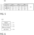
- FIG. 5 is a diagram illustrating a memory map according to the embodiment of the present invention.
- FIG. 6 is a diagram illustrating information about an element stored in the memory map of FIG. 6 .
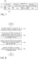
- FIG. 7 is a diagram illustrating a memory buffer according to the embodiment of the present invention.
- the memory management apparatus of an inverter stores and manages pieces of information about a plurality of allocation regions 121 allocated to a memory buffer 120 in a memory map 100 as a plurality of elements 110.
- data for controlling operation of an inverter is stored in the memory buffer 120.
- the memory management apparatus of an inverter includes an index setting unit 210, an index storing unit 220, an element searching unit 230, and a data deleting unit 240.
- the index setting unit 210 sets map indexes 111 in the plurality of elements 110 stored in the memory map 100.
- the index storing unit 220 stores each of the map indexes 111 of the memory map 100 in a corresponding one of the plurality of allocation regions 121 allocated to the memory buffer 120.
- the memory map 100 stores attribute information including the map index 111, a size 112 of the allocation region 121, a start address 113, and a use state 114 for each of the plurality of elements 110.
- the memory buffer 120 stores a memory buffer address 122, the map index 111 corresponding to each element 110 of the memory map 100, and data 124 using the memory buffer 120.
- the index storing unit 220 stores the map index 111 in the start address of each of the plurality of allocation regions 121.
- the memory buffer 120 stores the data 124 from an address subsequent to the start address in which the map index 111 is stored.
- memory buffer addresses 0 to 3 122 may be allocated to a first allocation region 121, and memory buffer addresses 4 to 8 122 may be allocated to a second allocation region 121.
- Memory buffer addresses 9 to 11 122 may be allocated to a third allocation region 121, and memory buffer addresses 12 to 16 122 may be allocated to a fourth allocation region 121.
- a map index (Map Index 0) 111 is stored in a start address (address 0) of the first allocation region (Allocation 1) 121, and the data 124 is stored in addresses 1 to 3 subsequent to the start address (address 0).
- a map index (Map Index 1) 111 is stored in a start address (address 4) of the second allocation region (Allocation 2) 121, and the data 124 is stored in addresses 5 to 8 subsequent to the start address (address 4).
- a map index (Map Index 2) 111 is stored in a start address (address 9) of the third allocation region (Allocation 3) 121, and the data 124 is stored in addresses 10 and 11 subsequent to the start address (address 9).
- a map index (Map Index 3) 111 is stored in a start address (address 12) of the fourth allocation region (Allocation 4) 121, and the data 124 is stored in addresses 13 to 16 subsequent to the start address (address 12).
- a first element the map index (Map Index 0) is set, and a memory size of 4, the start address (address 0), and a use state (in use (Y)) corresponding to the first allocation region (Allocation 1) 121 of the memory buffer 120 are stored.
- the map index (Map Index 1) is set, and a memory size of 5, the start address (address 4), and a use state (in use (Y)) corresponding to the second allocation region (Allocation 2) 121 of the memory buffer 120 are stored.
- a third element the map index (Map Index 2) is set, and a memory size of 3, the start address (address 9), and a use state (not in use (N)) corresponding to the third allocation region (Allocation 3) 121 of the memory buffer 120 are stored.
- the map index (Map Index 3) is set, and a memory size of 5, the start address (address 12), and a use state (in use (Y)) corresponding to the fourth allocation region (Allocation 4) 121 of the memory buffer 120 are stored.
- the element searching unit 230 searches the memory map 100 for the elements 110 using the map indexes 111 stored in the memory buffer 120.
- the element searching unit 230 may access an address immediately preceding an address in which the data 124 to be deleted is stored, read the map index 111, and access the element 110 including the read map index 111.
- the element searching unit 230 accesses address 4 immediately preceding addresses 5 to 8 in which the data is stored, determines the map index (Map Index 1), and accesses the second element (Element 2) including the map index (Map Index 1) read from the memory map 100.
- the memory management apparatus of an inverter has an advantage in that a specific element may be more rapidly and easily searched for in the memory map 100 using the map index 111.
- the data deleting unit 240 changes the use state of the element 110 found by the element searching unit 230 from "in use” to "not in use” and deletes the data stored in the memory buffer 120.
- the data deleting unit 240 may change the use state of the second element 2 from "in use (Y)” to “not in use (N)” and delete the data stored in the memory buffer 120.
- the memory management apparatus of an inverter according to the embodiment of the present invention may be relatively rapidly and efficiently operated when data about a corresponding allocation region in the memory buffer 120 is deleted.
- the memory management apparatus of an inverter according to the embodiment of the present invention may be effectively applied to an embedded system which uses a limited resource and a low performance component.
- FIG. 8 is a flowchart illustrating a memory management method of an inverter according to an embodiment of the present invention.
- the memory management method of an inverter is a method of storing and managing pieces of information about the plurality of allocation regions 121 allocated to the memory buffer 120 in the memory map 100 as the plurality of elements 110.
- data for controlling operation of an inverter is stored in the memory buffer 120.
- the memory management method of an inverter may include setting the map indexes 111 to the plurality of elements 110 stored in the memory map 100 (S10), storing each of the map indexes 111 in a corresponding one of the plurality of allocation regions 121 allocated to the memory buffer 120 (S20), and searching the memory map 100 for the elements 110 using the map indexes 111 stored in the memory buffer 120 (S30).
- the memory management apparatus of an inverter has an advantage in that a specific element may be more rapidly and easily searched for in the memory map 100 using the map index 111.
- the map index 111 is stored in the start address of each of the plurality of allocation regions 121, and the data 124 is stored from an address subsequent to the start address in which the map index 111 is stored.
- the memory management method of an inverter may further include changing a use state of the found element 110 from "in use” to "not in use” and deleting the data stored in the memory buffer 120.
- the memory management method of an inverter according to the embodiment of the present invention may be relatively rapidly and efficiently operated when data about a corresponding allocation region in the memory buffer 120 is deleted.
- the memory management method of an inverter according to the embodiment of the present invention may be effectively applied to an embedded system which uses a limited resource and a low performance component.
- a specific element can be more rapidly and easily searched for in a memory map using a map index.
- a memory management apparatus of an inverter can be relatively rapidly and efficiently operated when data about a corresponding allocation region in a memory buffer is deleted.
- the memory management apparatus can be effectively applied to an embedded system which uses a limited resource and a low performance component.
Landscapes
- Engineering & Computer Science (AREA)
- Theoretical Computer Science (AREA)
- Physics & Mathematics (AREA)
- General Engineering & Computer Science (AREA)
- General Physics & Mathematics (AREA)
- Inverter Devices (AREA)
- Memory System (AREA)
- Human Computer Interaction (AREA)
Applications Claiming Priority (1)
| Application Number | Priority Date | Filing Date | Title |
|---|---|---|---|
| KR1020190024813A KR20200106368A (ko) | 2019-03-04 | 2019-03-04 | 인버터의 메모리 관리 장치 및 방법 |
Publications (1)
| Publication Number | Publication Date |
|---|---|
| EP3706002A1 true EP3706002A1 (de) | 2020-09-09 |
Family
ID=68240693
Family Applications (1)
| Application Number | Title | Priority Date | Filing Date |
|---|---|---|---|
| EP19201751.5A Withdrawn EP3706002A1 (de) | 2019-03-04 | 2019-10-07 | Speicherverwaltungsvorrichtung und -verfahren eines wechselrichters |
Country Status (5)
| Country | Link |
|---|---|
| US (1) | US20200285576A1 (de) |
| EP (1) | EP3706002A1 (de) |
| JP (1) | JP2020144833A (de) |
| KR (1) | KR20200106368A (de) |
| CN (1) | CN111651370A (de) |
Citations (3)
| Publication number | Priority date | Publication date | Assignee | Title |
|---|---|---|---|---|
| EP2492816A1 (de) * | 2011-02-25 | 2012-08-29 | Siemens Aktiengesellschaft | Verfahren zur Verwaltung des physikalischen Speichers einer Datenspeicherung und Datenspeicher-Verwaltungssystem |
| US20150169570A1 (en) * | 2013-12-18 | 2015-06-18 | Samsung Electronics Co., Ltd. | Method and device for managing data |
| EP3240186A1 (de) * | 2016-04-25 | 2017-11-01 | LSIS Co., Ltd. | Vorrichtung zur steuerung eines umrichters |
-
2019
- 2019-03-04 KR KR1020190024813A patent/KR20200106368A/ko not_active Withdrawn
- 2019-09-20 CN CN201910895098.4A patent/CN111651370A/zh not_active Withdrawn
- 2019-10-07 EP EP19201751.5A patent/EP3706002A1/de not_active Withdrawn
- 2019-10-07 US US16/594,862 patent/US20200285576A1/en not_active Abandoned
- 2019-10-07 JP JP2019184554A patent/JP2020144833A/ja not_active Ceased
Patent Citations (3)
| Publication number | Priority date | Publication date | Assignee | Title |
|---|---|---|---|---|
| EP2492816A1 (de) * | 2011-02-25 | 2012-08-29 | Siemens Aktiengesellschaft | Verfahren zur Verwaltung des physikalischen Speichers einer Datenspeicherung und Datenspeicher-Verwaltungssystem |
| US20150169570A1 (en) * | 2013-12-18 | 2015-06-18 | Samsung Electronics Co., Ltd. | Method and device for managing data |
| EP3240186A1 (de) * | 2016-04-25 | 2017-11-01 | LSIS Co., Ltd. | Vorrichtung zur steuerung eines umrichters |
Also Published As
| Publication number | Publication date |
|---|---|
| CN111651370A (zh) | 2020-09-11 |
| KR20200106368A (ko) | 2020-09-14 |
| US20200285576A1 (en) | 2020-09-10 |
| JP2020144833A (ja) | 2020-09-10 |
Similar Documents
| Publication | Publication Date | Title |
|---|---|---|
| US9317204B2 (en) | System and method for I/O optimization in a multi-queued environment | |
| WO2007005562A2 (en) | Shared file system management between independent operating systems | |
| KR102276912B1 (ko) | 스토리지 시스템 및 이의 동작 방법 | |
| CN106648463B (zh) | Nand Flash块管理方法和系统 | |
| JPH1131102A (ja) | データ記憶システム及び同システムに適用するアクセス制御方法 | |
| US20190227918A1 (en) | Method for allocating memory resources, chip and non-transitory readable medium | |
| CN112363959B (zh) | 一种数据寻址方法、存储装置、芯片和数据存储系统 | |
| KR20200060758A (ko) | 메모리 어드레싱 방법 및 관련 컨트롤러, 메모리 장치 및 호스트 | |
| KR102653373B1 (ko) | 컨트롤러 및 컨트롤러의 동작방법 | |
| CN106598504B (zh) | 数据存储方法及装置 | |
| US9081664B2 (en) | Memory system capable of preventing data destruction | |
| KR20220036169A (ko) | 메모리 시스템 및 데이터 처리 시스템 | |
| CN108664577A (zh) | 一种基于flash空闲区的文件管理方法及系统 | |
| US12430242B2 (en) | Flash memory access method and apparatus | |
| US20060250720A1 (en) | Portable data storage device and method of dynamic memory management therefor | |
| JP4758794B2 (ja) | メモリ領域割り当て制御装置、メモリ領域割り当て制御プログラム、及びメモリ領域割り当て制御方法 | |
| EP3706002A1 (de) | Speicherverwaltungsvorrichtung und -verfahren eines wechselrichters | |
| US10990323B2 (en) | Flash memory controller, memory device and method for accessing flash memory module | |
| US8341334B2 (en) | Flash memory apparatus and method for operating the same and data storage system | |
| US9058113B2 (en) | Storage region providing device, storage region providing method, and recording medium | |
| CN116431340A (zh) | 一种物理内存分配方法、装置、设备及存储介质 | |
| JPH0652691A (ja) | 半導体ディスク装置 | |
| KR100479170B1 (ko) | 메모리 억세스 제어장치 및 방법 | |
| US9588909B2 (en) | Information processing technique to manage security attributes of data generated in different modes | |
| US20240241657A1 (en) | Storage device and method of operating the same |
Legal Events
| Date | Code | Title | Description |
|---|---|---|---|
| PUAI | Public reference made under article 153(3) epc to a published international application that has entered the european phase |
Free format text: ORIGINAL CODE: 0009012 |
|
| STAA | Information on the status of an ep patent application or granted ep patent |
Free format text: STATUS: THE APPLICATION HAS BEEN PUBLISHED |
|
| AK | Designated contracting states |
Kind code of ref document: A1 Designated state(s): AL AT BE BG CH CY CZ DE DK EE ES FI FR GB GR HR HU IE IS IT LI LT LU LV MC MK MT NL NO PL PT RO RS SE SI SK SM TR |
|
| AX | Request for extension of the european patent |
Extension state: BA ME |
|
| STAA | Information on the status of an ep patent application or granted ep patent |
Free format text: STATUS: THE APPLICATION IS DEEMED TO BE WITHDRAWN |
|
| 18D | Application deemed to be withdrawn |
Effective date: 20210310 |