EP3705775B1 - Eingebaute led-beleuchtungseinheit - Google Patents
Eingebaute led-beleuchtungseinheit Download PDFInfo
- Publication number
- EP3705775B1 EP3705775B1 EP20156577.7A EP20156577A EP3705775B1 EP 3705775 B1 EP3705775 B1 EP 3705775B1 EP 20156577 A EP20156577 A EP 20156577A EP 3705775 B1 EP3705775 B1 EP 3705775B1
- Authority
- EP
- European Patent Office
- Prior art keywords
- light unit
- led
- plate
- hole
- support
- Prior art date
- Legal status (The legal status is an assumption and is not a legal conclusion. Google has not performed a legal analysis and makes no representation as to the accuracy of the status listed.)
- Active
Links
Images

Classifications
-
- F—MECHANICAL ENGINEERING; LIGHTING; HEATING; WEAPONS; BLASTING
- F21—LIGHTING
- F21S—NON-PORTABLE LIGHTING DEVICES; SYSTEMS THEREOF; VEHICLE LIGHTING DEVICES SPECIALLY ADAPTED FOR VEHICLE EXTERIORS
- F21S8/00—Lighting devices intended for fixed installation
- F21S8/02—Lighting devices intended for fixed installation of recess-mounted type, e.g. downlighters
- F21S8/026—Lighting devices intended for fixed installation of recess-mounted type, e.g. downlighters intended to be recessed in a ceiling or like overhead structure, e.g. suspended ceiling
-
- F—MECHANICAL ENGINEERING; LIGHTING; HEATING; WEAPONS; BLASTING
- F21—LIGHTING
- F21V—FUNCTIONAL FEATURES OR DETAILS OF LIGHTING DEVICES OR SYSTEMS THEREOF; STRUCTURAL COMBINATIONS OF LIGHTING DEVICES WITH OTHER ARTICLES, NOT OTHERWISE PROVIDED FOR
- F21V15/00—Protecting lighting devices from damage
- F21V15/01—Housings, e.g. material or assembling of housing parts
-
- F—MECHANICAL ENGINEERING; LIGHTING; HEATING; WEAPONS; BLASTING
- F21—LIGHTING
- F21V—FUNCTIONAL FEATURES OR DETAILS OF LIGHTING DEVICES OR SYSTEMS THEREOF; STRUCTURAL COMBINATIONS OF LIGHTING DEVICES WITH OTHER ARTICLES, NOT OTHERWISE PROVIDED FOR
- F21V17/00—Fastening of component parts of lighting devices, e.g. shades, globes, refractors, reflectors, filters, screens, grids or protective cages
- F21V17/10—Fastening of component parts of lighting devices, e.g. shades, globes, refractors, reflectors, filters, screens, grids or protective cages characterised by specific fastening means or way of fastening
- F21V17/104—Fastening of component parts of lighting devices, e.g. shades, globes, refractors, reflectors, filters, screens, grids or protective cages characterised by specific fastening means or way of fastening using feather joints, e.g. tongues and grooves, with or without friction
-
- F—MECHANICAL ENGINEERING; LIGHTING; HEATING; WEAPONS; BLASTING
- F21—LIGHTING
- F21V—FUNCTIONAL FEATURES OR DETAILS OF LIGHTING DEVICES OR SYSTEMS THEREOF; STRUCTURAL COMBINATIONS OF LIGHTING DEVICES WITH OTHER ARTICLES, NOT OTHERWISE PROVIDED FOR
- F21V19/00—Fastening of light sources or lamp holders
- F21V19/04—Fastening of light sources or lamp holders with provision for changing light source, e.g. turret
-
- F—MECHANICAL ENGINEERING; LIGHTING; HEATING; WEAPONS; BLASTING
- F21—LIGHTING
- F21V—FUNCTIONAL FEATURES OR DETAILS OF LIGHTING DEVICES OR SYSTEMS THEREOF; STRUCTURAL COMBINATIONS OF LIGHTING DEVICES WITH OTHER ARTICLES, NOT OTHERWISE PROVIDED FOR
- F21V21/00—Supporting, suspending, or attaching arrangements for lighting devices; Hand grips
- F21V21/02—Wall, ceiling, or floor bases; Fixing pendants or arms to the bases
- F21V21/04—Recessed bases
- F21V21/041—Mounting arrangements specially adapted for false ceiling panels or partition walls made of plates
-
- F—MECHANICAL ENGINEERING; LIGHTING; HEATING; WEAPONS; BLASTING
- F21—LIGHTING
- F21Y—INDEXING SCHEME ASSOCIATED WITH SUBCLASSES F21K, F21L, F21S and F21V, RELATING TO THE FORM OR THE KIND OF THE LIGHT SOURCES OR OF THE COLOUR OF THE LIGHT EMITTED
- F21Y2115/00—Light-generating elements of semiconductor light sources
- F21Y2115/10—Light-emitting diodes [LED]
Definitions
- the present invention relates to a recessed LED light unit, having the features set out in main claim 1.
- these recessed light units comprise a plate-like support which has a small thickness and to which the light source is fixed, for example, an LED element, and provided with lateral wings for engagement with the internal portion of the plate to which the light unit is applied.
- the support There is fixed to the support a plate-like member which remains externally visible during the application of the light unit and which has a through-opening, through which the light emitted by the LED element is emitted outwards. Therefore, it is interposed between the support and the plate-like member, substantially in vertical alignment with the opening.
- Lighting devices of this type do not generally allow the LED element to be readily removed from the light unit, once the application to the wall has been carried out.
- the plate-like member which remains visible externally on the wall is subjected to the external levelling with the plasterboard sheet. Therefore, if it is necessary to gain access to the LED, for example, in order to replace it if necessary, it is necessary to dismantle the surface finish which is associated with the plate-like member and to remove the support from the anchoring seat which is provided in the plasterboard sheet. This operation, though it is not required often as a result of the long life of the LED elements, is found to be rather complex and difficult when it is necessary.
- the main objective of the invention is to provide an LED light unit for recessed applications which is structurally and functionally configured to overcome the limitations set out above with reference to the currently available solutions. This object and other objects which will be appreciated more clearly below are achieved by the invention by means of a recessed LED light unit which is constructed according to the appended claims.
- a recessed LED light unit in particular for being applied to plates which constitute false walls and/or false ceilings, comprises a support for fixing an LED element which is provided with lateral wings for engagement with the internal portion of the sheet, to which the light unit is applied, a plate-like member which is capable of being fixed to the support and which has a through-opening, through which the light emitted by the LED element of the light unit is emitted outwards, the LED element being mounted in a position interposed between the support and the plate-like member, substantially in vertical alignment with the opening, the LED light unit further comprising a plate-like element which is interposed between the support and the member and which is mounted in a manner with limited sliding on the member, the plate-like element being provided with a first through-hole and a second through-hole, which are adjacent to each other, the first hole being capable of being engaged by a screen or lens element, and the plate-like element being movable between a first position, in which the first hole is arranged in
- the LED element is capable of being fixed to the support by way of screw means, which can be screwed or unscrewed, from the outer side of the light unit, by means of a screwing tool which is guided through the opening and the second hole.
- the LED element is capable of being fixed to the support by way of magnetic connection means.
- the diameter of the second hole is selected so as to have a value between 9 and 16 mm.
- the support is constructed from a thermally conductive material for discharging the heat produced by the LED element.
- the plate-like element is at least partially received inside a seat which is formed in the member and which has such a formation as to guide the element during the sliding movement between the first position and the second position.
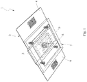
- FIG. 1 an embodiment of a recessed LED light unit which is constructed according to the present invention.
- the unit is mainly configured for applications on sheets L (see Figure 8 ), for example, of plasterboard, which constitute false walls and/or false ceilings.
- sheets L for example, of plasterboard, which constitute false walls and/or false ceilings.
- the wall constructed with plasterboard sheets is positioned with spacing from the rear wall/ceiling and in the gap which has been produced there is received the rear portion of the light unit.
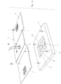
- the light unit 1 is constituted by two main portions, which are different from each other and intended to be mutually assembled, as will be appreciated in greater detail below.
- the light unit comprises a plate-like support 2, to which there is fixed an LED element 3 (as a light source for the light unit).
- the support is provided with a pair of opposite lateral wings 4 for engagement with the internal portion of the plasterboard sheet L, to which the light unit is intended to be applied.
- the support is preferably constructed from a material with high thermal conductivity (for example, from aluminium or other similar material or metal alloy which is suitable for the purpose), in order to rapidly dissipate the heat produced by the LED.
- the LED is applied to the support by way of screw type fixing means 5.
- a preferred embodiment provides for a plate 6 of the printed circuit board of the LED (also referred to using the term PCB) to be provided with eyelets or notches for engaging one or more securing screws 5.
- the plate 6 of the printed circuit board can be fixed to the support 2 by way of magnetic connection means.
- the second portion of the light unit is constituted by a plate-like member 7 which is capable of being fixed to the support 2 and which has a through-opening 8, which is preferably formed as a cylindrical hole, through which the light emitted by the LED element 3 is emitted outwards.
- the LED is mounted in a position interposed between the support 2 and the plate-like member 7 so as to be substantially in vertical alignment with the opening (that is to say, the light source of the LED is arranged in the direction of the main axis of the cylindrical hole which defines the opening 8). It will be understood that it is alternatively possible to provide holes having a formation different from the cylindrical one described above.
- the plate-like member 7 serves to protect the LED in the closure of the seat which is formed in the plasterboard sheet L and therefore remains visible once the application is complete. It is further advantageously constructed from a material which makes the operation of external levelling with the plasterboard sheet easier.
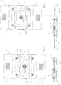
- the light unit 1 further comprises a plate-like element which is designated 9 and which is mounted in a manner with limited sliding on the member 7 and which is provided with a first and a second hole, designated 10 and 11, respectively, which extend through the thickness of the element 9 and which are mutually adjacent, and with respective parallel main axes.
- the first hole 10 is further closed by the engagement of an element 12 in the form of a screen or lens, which is suitable for screening the hole 8 or diffusing the light emitted by the LED with a preselected angulation of the light rays, respectively.
- the element 12 can be constructed as a reflector of the light rays emitted by the LED.
- the holes 10, 11 are further preferably constructed with a circular cross-section and with an identical diameter with respect to each other, this selection in any case representing a preferred but non-limiting embodiment.
- the plate-like element 9 is at least partially received in a manner guided inside a seat 13 which is formed in the member 7, which has such a formation as to guide the element 9 during a translational sliding movement, the magnitude of which is delimited by the opposite end of the seat.
- the element 9 is movable in translation between a first position ( Figure 4 ), in which the first hole 10 is arranged in correspondence with the opening 8 (that is to say, in vertical alignment with the opening 8) so as to allow the diffusion outwards of the light emitted by the LED, and a second position ( Figure 5 ), in which the second hole 11 is the one to be moved in correspondence with the opening 8.
- the diameter of the second hole 11 is preferably selected with a value between 9 mm and 16 mm, and the LED element 3 and in particular the circuit board 6 thereof to have such dimensions as to be able to be removed/inserted with a reduced relative play, through the opening 8 and the hole 11.
- the plate-like element 9 is arranged in the first position, in which the hole 10 is vertically aligned with the opening 8, and the light emitted by the LED element 3 is diffused outwards through the screen or lens element 12 which engages with the hole 10.
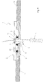
- the plate-like element 9 is initially moved from the first position to the second position (for example, by means of the tip of a screwdriver introduced from outside into the opening 8, in order to urge the element 9 into the sliding movement). Once this position is reached, the fixing screws 5 of the LED are accessible through the opening 8 and the hole 11 and can be unscrewed with a screwdriver tool C which is introduced through them from outside. Once the screws 5 are released, the LED element 3 can be removed by causing it to pass through the hole 11 in order to then be discharged from the opening 8 (shown in Figure 8 with broken lines).
- the electrical connection wires of the LED are selected with a suitable length so as to allow the removal of the LED from the light unit with the wires connected thereto ( Figure 8 ). After replacement, the new LED element 3 can be inserted again through the opening 8 and the hole 11 in order to fix the corresponding screws 5 against the support 2.
- the removal operation is further facilitated. In fact, it is simply necessary to move the LED away from the support by applying a removal force greater than the magnetic attraction forces so as to separate the LED from the support, and to allow the removal thereof from the light unit, in a manner generally similar to the preceding embodiment.
- the recessed light unit according to the invention ensures the interchangeability of the LED element which is received in the light unit, without requiring disassembly or removal of any of the structural members of the light unit, thereby preserving the recessed application originally brought about.
Landscapes
- Engineering & Computer Science (AREA)
- General Engineering & Computer Science (AREA)
- Illuminated Signs And Luminous Advertising (AREA)
- Arrangement Of Elements, Cooling, Sealing, Or The Like Of Lighting Devices (AREA)
- Non-Portable Lighting Devices Or Systems Thereof (AREA)
Claims (6)
- LED-Einbauleuchte, insbesondere zum Anbringen an Platten, die Zwischenwände und/oder Zwischendecken bilden, umfassend:einen Träger (2), an dem ein LED-Element (3) befestigt ist, das mit seitlichen Flügeln (4) zum Eingriff mit dem inneren Abschnitt einer Platte (L) versehen ist, an der die Leuchte angebracht ist, ein plattenartiges Bauteil (7), das am Träger (2) befestigbar ist und das eine Durchgangsöffnung (8) aufweist, durch die das vom LED-Element (3) der Leuchte emittierte Licht nach außen abgestrahlt wird, wobei das LED-Element (3) in einer zwischen dem Träger (2) und dem plattenartigen Bauteil (7) angeordneten Position im Wesentlichen in vertikaler Ausrichtung mit der Durchgangsöffnung (8) montiert ist,dadurch gekennzeichnet, dass diese ein plattenartiges Element (9) umfasst, das zwischen dem Träger (2) und dem plattenartigen Bauteil (7) angeordnet ist und das am Bauteil begrenzt verschiebbar montiert ist, dass das plattenartige Element (9) mit einer ersten Durchgangsöffnung und einer zweiten Durchgangsöffnung (10, 11) versehen ist, die aneinander angrenzen, wobei die erste Durchgangsöffnung (10) mit einem Schirm- oder Linsenelement (12) in Eingriff bringbar ist, und dass das plattenartige Element (9) zwischen einer ersten Position, in der die erste Durchgangsöffnung (10) entsprechend der Durchgangsöffnung (8) zum Streuen des vom LED-Element (3) emittierten Lichts angeordnet ist, und einer zweiten Position, in der die zweite Durchgangsöffnung (11) entsprechend der Durchgangsöffnung (8) angeordnet ist, bewegbar ist, wobei das LED-Element (3) durch die zweite Durchgangsöffnung (11) und die Durchgangsöffnung (8) aus der Leuchte herausnehmbar ist.
- LED-Einbauleuchte nach Anspruch 1, wobei das LED-Element (3) am Träger (2) mittels einer Schraubeinrichtung befestigbar ist, die von der Außenseite der Leuchteinheit mittels eines Schraubwerkzeugs, das durch die Durchgangsöffnung (8) und die zweite Durchgangsbohrung (11) geführt ist, angeschraubt oder abgeschraubt werden kann.
- LED-Einbauleuchte nach Anspruch 1, wobei das LED-Element (3) mittels einer magnetischen Verbindungseinrichtung am Träger (2) befestigbar ist.
- LED-Einbauleuchte nach einem der vorhergehenden Ansprüche, wobei der Durchmesser der zweiten Durchgangsöffnung (11) so gewählt ist, dass dieser einen Wert zwischen 9 und 16 mm aufweist.
- LED-Einbauleuchte nach einem der vorhergehenden Ansprüche, wobei der Träger (2) aus einem wärmeleitenden Material zum Ableiten der vom LED-Element (3) erzeugten Wärme hergestellt ist.
- LED-Einbauleuchte nach einem der vorhergehenden Ansprüche, wobei das plattenförmige Element (9) zumindest teilweise in einem Sitz (13) aufgenommen ist, der im plattenförmigen Bauteil (7) ausgebildet ist und der eine solche Formgebung aufweist, dass dieser das plattenförmige Element (9) während der Verschiebebewegung zwischen der ersten Position und der zweiten Position führt.
Applications Claiming Priority (1)
| Application Number | Priority Date | Filing Date | Title |
|---|---|---|---|
| IT202019000000613U IT201900000613U1 (it) | 2019-02-22 | 2019-02-22 | Gruppo luce a LED da incasso |
Publications (2)
| Publication Number | Publication Date |
|---|---|
| EP3705775A1 EP3705775A1 (de) | 2020-09-09 |
| EP3705775B1 true EP3705775B1 (de) | 2021-04-14 |
Family
ID=69845013
Family Applications (1)
| Application Number | Title | Priority Date | Filing Date |
|---|---|---|---|
| EP20156577.7A Active EP3705775B1 (de) | 2019-02-22 | 2020-02-11 | Eingebaute led-beleuchtungseinheit |
Country Status (3)
| Country | Link |
|---|---|
| EP (1) | EP3705775B1 (de) |
| ES (1) | ES2882013T3 (de) |
| IT (1) | IT201900000613U1 (de) |
Families Citing this family (1)
| Publication number | Priority date | Publication date | Assignee | Title |
|---|---|---|---|---|
| DE102021100917B4 (de) * | 2021-01-18 | 2024-02-29 | Rüdiger Lanz | Scheinwerfer mit wechselnden LED-Leuchtmitteln |
Family Cites Families (3)
| Publication number | Priority date | Publication date | Assignee | Title |
|---|---|---|---|---|
| US7478931B2 (en) * | 2006-06-30 | 2009-01-20 | Ruud Lighting, Inc. | Lighting fixture service access |
| ITVI20130086U1 (it) * | 2013-12-20 | 2015-06-21 | Belfiore S R L | Faretto da incasso |
| WO2016185299A1 (en) * | 2015-04-13 | 2016-11-24 | Buzzi & Buzzi Srl | Lighting device |
-
2019
- 2019-02-22 IT IT202019000000613U patent/IT201900000613U1/it unknown
-
2020
- 2020-02-11 ES ES20156577T patent/ES2882013T3/es active Active
- 2020-02-11 EP EP20156577.7A patent/EP3705775B1/de active Active
Non-Patent Citations (1)
| Title |
|---|
| None * |
Also Published As
| Publication number | Publication date |
|---|---|
| EP3705775A1 (de) | 2020-09-09 |
| ES2882013T3 (es) | 2021-11-30 |
| IT201900000613U1 (it) | 2020-08-22 |
Similar Documents
| Publication | Publication Date | Title |
|---|---|---|
| US7572034B2 (en) | Multiple side illumination assembly | |
| DE102012202148A1 (de) | Lichtbandsystem | |
| DE202011051974U1 (de) | Leuchtdiodenröhre | |
| EP3450840B1 (de) | Lampenwechselsystem für eine automatisierte leuchte | |
| EP3705775B1 (de) | Eingebaute led-beleuchtungseinheit | |
| DE202015009561U1 (de) | LED-Lampe und LED-Lichtquellenmodul dafür | |
| US10190737B2 (en) | Troffer light fixture retrofitting kit and method to install the same | |
| US11506364B2 (en) | Connection system for a luminaire, and a lighting system using the connection system | |
| AT16083U1 (de) | Feuchtraumleuchte in Wannenbauform | |
| EP2647907B1 (de) | Leuchteneinsatz mit reflektor | |
| EP2184628A2 (de) | Leuchte, insbesondere Not-, Rettungs oder Sicherheitsleuchte | |
| EP2849550B1 (de) | Anpassungsvorrichtung für Kabelführungsarm | |
| EP2363634B1 (de) | Unterputz-LED-Leuchte, insbesondere Deckenleuchte | |
| EP3369986A1 (de) | Leuchte | |
| JP2007122936A (ja) | 照明器具 | |
| DE102008005779A1 (de) | Montagesystem für Funktionsmodule | |
| EP2650604B1 (de) | Leuchte mit einem Trägerelement für ein LED-Modul | |
| GB2490956A (en) | Lighting unit with demountable lamp housing, fireproofing and removable waterproofing structure | |
| AT509626B1 (de) | Modulares led beleuchtungssystem mit partieller lichtstärkenanpassung | |
| EP2557355B1 (de) | Leuchte | |
| EP3879169B1 (de) | Halterung zur befestigung eines leuchtkörpers | |
| KR100390306B1 (ko) | 형광등기구의 장착장치 | |
| JP6909381B2 (ja) | 照明器具 | |
| JP2002195235A (ja) | 定盤へ機器を固定するための固定装置 | |
| EP2924352B1 (de) | Leuchte mit elastisches Blendungselement |
Legal Events
| Date | Code | Title | Description |
|---|---|---|---|
| PUAI | Public reference made under article 153(3) epc to a published international application that has entered the european phase |
Free format text: ORIGINAL CODE: 0009012 |
|
| STAA | Information on the status of an ep patent application or granted ep patent |
Free format text: STATUS: THE APPLICATION HAS BEEN PUBLISHED |
|
| AK | Designated contracting states |
Kind code of ref document: A1 Designated state(s): AL AT BE BG CH CY CZ DE DK EE ES FI FR GB GR HR HU IE IS IT LI LT LU LV MC MK MT NL NO PL PT RO RS SE SI SK SM TR |
|
| AX | Request for extension of the european patent |
Extension state: BA ME |
|
| STAA | Information on the status of an ep patent application or granted ep patent |
Free format text: STATUS: REQUEST FOR EXAMINATION WAS MADE |
|
| 17P | Request for examination filed |
Effective date: 20200928 |
|
| RBV | Designated contracting states (corrected) |
Designated state(s): AL AT BE BG CH CY CZ DE DK EE ES FI FR GB GR HR HU IE IS IT LI LT LU LV MC MK MT NL NO PL PT RO RS SE SI SK SM TR |
|
| RIC1 | Information provided on ipc code assigned before grant |
Ipc: F21V 17/10 20060101ALI20201027BHEP Ipc: F21S 8/02 20060101AFI20201027BHEP Ipc: F21V 19/04 20060101ALI20201027BHEP Ipc: F21V 21/04 20060101ALI20201027BHEP Ipc: F21Y 115/10 20160101ALN20201027BHEP Ipc: F21V 15/01 20060101ALI20201027BHEP |
|
| RIC1 | Information provided on ipc code assigned before grant |
Ipc: F21S 8/02 20060101AFI20201216BHEP Ipc: F21V 19/04 20060101ALI20201216BHEP Ipc: F21Y 115/10 20160101ALN20201216BHEP Ipc: F21V 21/04 20060101ALI20201216BHEP Ipc: F21V 15/01 20060101ALI20201216BHEP Ipc: F21V 17/10 20060101ALI20201216BHEP |
|
| GRAP | Despatch of communication of intention to grant a patent |
Free format text: ORIGINAL CODE: EPIDOSNIGR1 |
|
| STAA | Information on the status of an ep patent application or granted ep patent |
Free format text: STATUS: GRANT OF PATENT IS INTENDED |
|
| RIC1 | Information provided on ipc code assigned before grant |
Ipc: F21V 21/04 20060101ALI20210119BHEP Ipc: F21V 19/04 20060101ALI20210119BHEP Ipc: F21S 8/02 20060101AFI20210119BHEP Ipc: F21V 15/01 20060101ALI20210119BHEP Ipc: F21V 17/10 20060101ALI20210119BHEP Ipc: F21Y 115/10 20160101ALN20210119BHEP |
|
| GRAS | Grant fee paid |
Free format text: ORIGINAL CODE: EPIDOSNIGR3 |
|
| INTG | Intention to grant announced |
Effective date: 20210208 |
|
| GRAA | (expected) grant |
Free format text: ORIGINAL CODE: 0009210 |
|
| STAA | Information on the status of an ep patent application or granted ep patent |
Free format text: STATUS: THE PATENT HAS BEEN GRANTED |
|
| AK | Designated contracting states |
Kind code of ref document: B1 Designated state(s): AL AT BE BG CH CY CZ DE DK EE ES FI FR GB GR HR HU IE IS IT LI LT LU LV MC MK MT NL NO PL PT RO RS SE SI SK SM TR |
|
| REG | Reference to a national code |
Ref country code: GB Ref legal event code: FG4D |
|
| REG | Reference to a national code |
Ref country code: CH Ref legal event code: EP |
|
| REG | Reference to a national code |
Ref country code: DE Ref legal event code: R096 Ref document number: 602020000056 Country of ref document: DE |
|
| REG | Reference to a national code |
Ref country code: IE Ref legal event code: FG4D |
|
| REG | Reference to a national code |
Ref country code: AT Ref legal event code: REF Ref document number: 1382714 Country of ref document: AT Kind code of ref document: T Effective date: 20210515 |
|
| REG | Reference to a national code |
Ref country code: GR Ref legal event code: EP Ref document number: 20210401429 Country of ref document: GR Effective date: 20210709 |
|
| REG | Reference to a national code |
Ref country code: LT Ref legal event code: MG9D |
|
| REG | Reference to a national code |
Ref country code: NL Ref legal event code: MP Effective date: 20210414 |
|
| PG25 | Lapsed in a contracting state [announced via postgrant information from national office to epo] |
Ref country code: NL Free format text: LAPSE BECAUSE OF FAILURE TO SUBMIT A TRANSLATION OF THE DESCRIPTION OR TO PAY THE FEE WITHIN THE PRESCRIBED TIME-LIMIT Effective date: 20210414 Ref country code: BG Free format text: LAPSE BECAUSE OF FAILURE TO SUBMIT A TRANSLATION OF THE DESCRIPTION OR TO PAY THE FEE WITHIN THE PRESCRIBED TIME-LIMIT Effective date: 20210714 Ref country code: LT Free format text: LAPSE BECAUSE OF FAILURE TO SUBMIT A TRANSLATION OF THE DESCRIPTION OR TO PAY THE FEE WITHIN THE PRESCRIBED TIME-LIMIT Effective date: 20210414 Ref country code: HR Free format text: LAPSE BECAUSE OF FAILURE TO SUBMIT A TRANSLATION OF THE DESCRIPTION OR TO PAY THE FEE WITHIN THE PRESCRIBED TIME-LIMIT Effective date: 20210414 Ref country code: FI Free format text: LAPSE BECAUSE OF FAILURE TO SUBMIT A TRANSLATION OF THE DESCRIPTION OR TO PAY THE FEE WITHIN THE PRESCRIBED TIME-LIMIT Effective date: 20210414 |
|
| PG25 | Lapsed in a contracting state [announced via postgrant information from national office to epo] |
Ref country code: SE Free format text: LAPSE BECAUSE OF FAILURE TO SUBMIT A TRANSLATION OF THE DESCRIPTION OR TO PAY THE FEE WITHIN THE PRESCRIBED TIME-LIMIT Effective date: 20210414 Ref country code: RS Free format text: LAPSE BECAUSE OF FAILURE TO SUBMIT A TRANSLATION OF THE DESCRIPTION OR TO PAY THE FEE WITHIN THE PRESCRIBED TIME-LIMIT Effective date: 20210414 Ref country code: PT Free format text: LAPSE BECAUSE OF FAILURE TO SUBMIT A TRANSLATION OF THE DESCRIPTION OR TO PAY THE FEE WITHIN THE PRESCRIBED TIME-LIMIT Effective date: 20210816 Ref country code: LV Free format text: LAPSE BECAUSE OF FAILURE TO SUBMIT A TRANSLATION OF THE DESCRIPTION OR TO PAY THE FEE WITHIN THE PRESCRIBED TIME-LIMIT Effective date: 20210414 Ref country code: PL Free format text: LAPSE BECAUSE OF FAILURE TO SUBMIT A TRANSLATION OF THE DESCRIPTION OR TO PAY THE FEE WITHIN THE PRESCRIBED TIME-LIMIT Effective date: 20210414 Ref country code: NO Free format text: LAPSE BECAUSE OF FAILURE TO SUBMIT A TRANSLATION OF THE DESCRIPTION OR TO PAY THE FEE WITHIN THE PRESCRIBED TIME-LIMIT Effective date: 20210714 Ref country code: IS Free format text: LAPSE BECAUSE OF FAILURE TO SUBMIT A TRANSLATION OF THE DESCRIPTION OR TO PAY THE FEE WITHIN THE PRESCRIBED TIME-LIMIT Effective date: 20210814 |
|
| REG | Reference to a national code |
Ref country code: ES Ref legal event code: FG2A Ref document number: 2882013 Country of ref document: ES Kind code of ref document: T3 Effective date: 20211130 |
|
| REG | Reference to a national code |
Ref country code: AT Ref legal event code: UEP Ref document number: 1382714 Country of ref document: AT Kind code of ref document: T Effective date: 20210414 |
|
| REG | Reference to a national code |
Ref country code: DE Ref legal event code: R097 Ref document number: 602020000056 Country of ref document: DE |
|
| PG25 | Lapsed in a contracting state [announced via postgrant information from national office to epo] |
Ref country code: SK Free format text: LAPSE BECAUSE OF FAILURE TO SUBMIT A TRANSLATION OF THE DESCRIPTION OR TO PAY THE FEE WITHIN THE PRESCRIBED TIME-LIMIT Effective date: 20210414 Ref country code: EE Free format text: LAPSE BECAUSE OF FAILURE TO SUBMIT A TRANSLATION OF THE DESCRIPTION OR TO PAY THE FEE WITHIN THE PRESCRIBED TIME-LIMIT Effective date: 20210414 Ref country code: RO Free format text: LAPSE BECAUSE OF FAILURE TO SUBMIT A TRANSLATION OF THE DESCRIPTION OR TO PAY THE FEE WITHIN THE PRESCRIBED TIME-LIMIT Effective date: 20210414 Ref country code: SM Free format text: LAPSE BECAUSE OF FAILURE TO SUBMIT A TRANSLATION OF THE DESCRIPTION OR TO PAY THE FEE WITHIN THE PRESCRIBED TIME-LIMIT Effective date: 20210414 Ref country code: CZ Free format text: LAPSE BECAUSE OF FAILURE TO SUBMIT A TRANSLATION OF THE DESCRIPTION OR TO PAY THE FEE WITHIN THE PRESCRIBED TIME-LIMIT Effective date: 20210414 Ref country code: DK Free format text: LAPSE BECAUSE OF FAILURE TO SUBMIT A TRANSLATION OF THE DESCRIPTION OR TO PAY THE FEE WITHIN THE PRESCRIBED TIME-LIMIT Effective date: 20210414 |
|
| PLBE | No opposition filed within time limit |
Free format text: ORIGINAL CODE: 0009261 |
|
| STAA | Information on the status of an ep patent application or granted ep patent |
Free format text: STATUS: NO OPPOSITION FILED WITHIN TIME LIMIT |
|
| 26N | No opposition filed |
Effective date: 20220117 |
|
| PG25 | Lapsed in a contracting state [announced via postgrant information from national office to epo] |
Ref country code: IS Free format text: LAPSE BECAUSE OF FAILURE TO SUBMIT A TRANSLATION OF THE DESCRIPTION OR TO PAY THE FEE WITHIN THE PRESCRIBED TIME-LIMIT Effective date: 20210814 Ref country code: AL Free format text: LAPSE BECAUSE OF FAILURE TO SUBMIT A TRANSLATION OF THE DESCRIPTION OR TO PAY THE FEE WITHIN THE PRESCRIBED TIME-LIMIT Effective date: 20210414 |
|
| PG25 | Lapsed in a contracting state [announced via postgrant information from national office to epo] |
Ref country code: MC Free format text: LAPSE BECAUSE OF FAILURE TO SUBMIT A TRANSLATION OF THE DESCRIPTION OR TO PAY THE FEE WITHIN THE PRESCRIBED TIME-LIMIT Effective date: 20210414 |
|
| REG | Reference to a national code |
Ref country code: BE Ref legal event code: MM Effective date: 20220228 |
|
| PG25 | Lapsed in a contracting state [announced via postgrant information from national office to epo] |
Ref country code: LU Free format text: LAPSE BECAUSE OF NON-PAYMENT OF DUE FEES Effective date: 20220211 |
|
| PG25 | Lapsed in a contracting state [announced via postgrant information from national office to epo] |
Ref country code: IE Free format text: LAPSE BECAUSE OF NON-PAYMENT OF DUE FEES Effective date: 20220211 |
|
| PG25 | Lapsed in a contracting state [announced via postgrant information from national office to epo] |
Ref country code: BE Free format text: LAPSE BECAUSE OF NON-PAYMENT OF DUE FEES Effective date: 20220228 |
|
| P01 | Opt-out of the competence of the unified patent court (upc) registered |
Effective date: 20230518 |
|
| REG | Reference to a national code |
Ref country code: CH Ref legal event code: PL |
|
| PG25 | Lapsed in a contracting state [announced via postgrant information from national office to epo] |
Ref country code: LI Free format text: LAPSE BECAUSE OF NON-PAYMENT OF DUE FEES Effective date: 20230228 Ref country code: CH Free format text: LAPSE BECAUSE OF NON-PAYMENT OF DUE FEES Effective date: 20230228 |
|
| PGFP | Annual fee paid to national office [announced via postgrant information from national office to epo] |
Ref country code: GR Payment date: 20240221 Year of fee payment: 5 |
|
| PG25 | Lapsed in a contracting state [announced via postgrant information from national office to epo] |
Ref country code: MK Free format text: LAPSE BECAUSE OF FAILURE TO SUBMIT A TRANSLATION OF THE DESCRIPTION OR TO PAY THE FEE WITHIN THE PRESCRIBED TIME-LIMIT Effective date: 20210414 Ref country code: CY Free format text: LAPSE BECAUSE OF FAILURE TO SUBMIT A TRANSLATION OF THE DESCRIPTION OR TO PAY THE FEE WITHIN THE PRESCRIBED TIME-LIMIT Effective date: 20210414 |
|
| PGFP | Annual fee paid to national office [announced via postgrant information from national office to epo] |
Ref country code: DE Payment date: 20240219 Year of fee payment: 5 Ref country code: GB Payment date: 20240219 Year of fee payment: 5 |
|
| PG25 | Lapsed in a contracting state [announced via postgrant information from national office to epo] |
Ref country code: HU Free format text: LAPSE BECAUSE OF FAILURE TO SUBMIT A TRANSLATION OF THE DESCRIPTION OR TO PAY THE FEE WITHIN THE PRESCRIBED TIME-LIMIT; INVALID AB INITIO Effective date: 20200211 |
|
| PGFP | Annual fee paid to national office [announced via postgrant information from national office to epo] |
Ref country code: IT Payment date: 20231201 Year of fee payment: 5 Ref country code: FR Payment date: 20240222 Year of fee payment: 5 |
|
| PGFP | Annual fee paid to national office [announced via postgrant information from national office to epo] |
Ref country code: ES Payment date: 20240328 Year of fee payment: 5 |
|
| PG25 | Lapsed in a contracting state [announced via postgrant information from national office to epo] |
Ref country code: MT Free format text: LAPSE BECAUSE OF FAILURE TO SUBMIT A TRANSLATION OF THE DESCRIPTION OR TO PAY THE FEE WITHIN THE PRESCRIBED TIME-LIMIT Effective date: 20210414 |
|
| PGFP | Annual fee paid to national office [announced via postgrant information from national office to epo] |
Ref country code: AT Payment date: 20250417 Year of fee payment: 5 |
|
| REG | Reference to a national code |
Ref country code: DE Ref legal event code: R119 Ref document number: 602020000056 Country of ref document: DE |
|
| PG25 | Lapsed in a contracting state [announced via postgrant information from national office to epo] |
Ref country code: GR Free format text: LAPSE BECAUSE OF NON-PAYMENT OF DUE FEES Effective date: 20250903 |
|
| GBPC | Gb: european patent ceased through non-payment of renewal fee |
Effective date: 20250211 |
|
| PG25 | Lapsed in a contracting state [announced via postgrant information from national office to epo] |
Ref country code: TR Free format text: LAPSE BECAUSE OF FAILURE TO SUBMIT A TRANSLATION OF THE DESCRIPTION OR TO PAY THE FEE WITHIN THE PRESCRIBED TIME-LIMIT Effective date: 20210414 |
|
| PG25 | Lapsed in a contracting state [announced via postgrant information from national office to epo] |
Ref country code: DE Free format text: LAPSE BECAUSE OF NON-PAYMENT OF DUE FEES Effective date: 20250902 |
|
| PG25 | Lapsed in a contracting state [announced via postgrant information from national office to epo] |
Ref country code: GB Free format text: LAPSE BECAUSE OF NON-PAYMENT OF DUE FEES Effective date: 20250211 |
|
| PG25 | Lapsed in a contracting state [announced via postgrant information from national office to epo] |
Ref country code: FR Free format text: LAPSE BECAUSE OF NON-PAYMENT OF DUE FEES Effective date: 20250228 Ref country code: IT Free format text: LAPSE BECAUSE OF NON-PAYMENT OF DUE FEES Effective date: 20250211 |
|
| REG | Reference to a national code |
Ref country code: ES Ref legal event code: FD2A Effective date: 20260327 |
|
| PG25 | Lapsed in a contracting state [announced via postgrant information from national office to epo] |
Ref country code: ES Free format text: LAPSE BECAUSE OF NON-PAYMENT OF DUE FEES Effective date: 20250212 |
|
| PG25 | Lapsed in a contracting state [announced via postgrant information from national office to epo] |
Ref country code: AT Free format text: LAPSE BECAUSE OF NON-PAYMENT OF DUE FEES Effective date: 20250211 |
|
| REG | Reference to a national code |
Ref country code: AT Ref legal event code: MM01 Ref document number: 1382714 Country of ref document: AT Kind code of ref document: T Effective date: 20250211 |