EP3450840B1 - Lampenwechselsystem für eine automatisierte leuchte - Google Patents
Lampenwechselsystem für eine automatisierte leuchte Download PDFInfo
- Publication number
- EP3450840B1 EP3450840B1 EP18192012.5A EP18192012A EP3450840B1 EP 3450840 B1 EP3450840 B1 EP 3450840B1 EP 18192012 A EP18192012 A EP 18192012A EP 3450840 B1 EP3450840 B1 EP 3450840B1
- Authority
- EP
- European Patent Office
- Prior art keywords
- lamp
- retaining clips
- mounting plate
- head
- lamp mounting
- Prior art date
- Legal status (The legal status is an assumption and is not a legal conclusion. Google has not performed a legal analysis and makes no representation as to the accuracy of the status listed.)
- Active
Links
Images


Classifications
-
- F—MECHANICAL ENGINEERING; LIGHTING; HEATING; WEAPONS; BLASTING
- F21—LIGHTING
- F21V—FUNCTIONAL FEATURES OR DETAILS OF LIGHTING DEVICES OR SYSTEMS THEREOF; STRUCTURAL COMBINATIONS OF LIGHTING DEVICES WITH OTHER ARTICLES, NOT OTHERWISE PROVIDED FOR
- F21V21/00—Supporting, suspending, or attaching arrangements for lighting devices; Hand grips
- F21V21/14—Adjustable mountings
- F21V21/30—Pivoted housings or frames
-
- F—MECHANICAL ENGINEERING; LIGHTING; HEATING; WEAPONS; BLASTING
- F21—LIGHTING
- F21S—NON-PORTABLE LIGHTING DEVICES; SYSTEMS THEREOF; VEHICLE LIGHTING DEVICES SPECIALLY ADAPTED FOR VEHICLE EXTERIORS
- F21S10/00—Lighting devices or systems producing a varying lighting effect
- F21S10/007—Lighting devices or systems producing a varying lighting effect using rotating transparent or colored disks, e.g. gobo wheels
-
- F—MECHANICAL ENGINEERING; LIGHTING; HEATING; WEAPONS; BLASTING
- F21—LIGHTING
- F21V—FUNCTIONAL FEATURES OR DETAILS OF LIGHTING DEVICES OR SYSTEMS THEREOF; STRUCTURAL COMBINATIONS OF LIGHTING DEVICES WITH OTHER ARTICLES, NOT OTHERWISE PROVIDED FOR
- F21V19/00—Fastening of light sources or lamp holders
- F21V19/02—Fastening of light sources or lamp holders with provision for adjustment, e.g. for focusing
-
- F—MECHANICAL ENGINEERING; LIGHTING; HEATING; WEAPONS; BLASTING
- F21—LIGHTING
- F21V—FUNCTIONAL FEATURES OR DETAILS OF LIGHTING DEVICES OR SYSTEMS THEREOF; STRUCTURAL COMBINATIONS OF LIGHTING DEVICES WITH OTHER ARTICLES, NOT OTHERWISE PROVIDED FOR
- F21V11/00—Screens not covered by groups F21V1/00, F21V3/00, F21V7/00 or F21V9/00
- F21V11/08—Screens not covered by groups F21V1/00, F21V3/00, F21V7/00 or F21V9/00 using diaphragms containing one or more apertures
- F21V11/10—Screens not covered by groups F21V1/00, F21V3/00, F21V7/00 or F21V9/00 using diaphragms containing one or more apertures of iris type
-
- F—MECHANICAL ENGINEERING; LIGHTING; HEATING; WEAPONS; BLASTING
- F21—LIGHTING
- F21V—FUNCTIONAL FEATURES OR DETAILS OF LIGHTING DEVICES OR SYSTEMS THEREOF; STRUCTURAL COMBINATIONS OF LIGHTING DEVICES WITH OTHER ARTICLES, NOT OTHERWISE PROVIDED FOR
- F21V14/00—Controlling the distribution of the light emitted by adjustment of elements
- F21V14/04—Controlling the distribution of the light emitted by adjustment of elements by movement of reflectors
-
- F—MECHANICAL ENGINEERING; LIGHTING; HEATING; WEAPONS; BLASTING
- F21—LIGHTING
- F21V—FUNCTIONAL FEATURES OR DETAILS OF LIGHTING DEVICES OR SYSTEMS THEREOF; STRUCTURAL COMBINATIONS OF LIGHTING DEVICES WITH OTHER ARTICLES, NOT OTHERWISE PROVIDED FOR
- F21V17/00—Fastening of component parts of lighting devices, e.g. shades, globes, refractors, reflectors, filters, screens, grids or protective cages
- F21V17/10—Fastening of component parts of lighting devices, e.g. shades, globes, refractors, reflectors, filters, screens, grids or protective cages characterised by specific fastening means or way of fastening
- F21V17/12—Fastening of component parts of lighting devices, e.g. shades, globes, refractors, reflectors, filters, screens, grids or protective cages characterised by specific fastening means or way of fastening by screwing
-
- F—MECHANICAL ENGINEERING; LIGHTING; HEATING; WEAPONS; BLASTING
- F21—LIGHTING
- F21V—FUNCTIONAL FEATURES OR DETAILS OF LIGHTING DEVICES OR SYSTEMS THEREOF; STRUCTURAL COMBINATIONS OF LIGHTING DEVICES WITH OTHER ARTICLES, NOT OTHERWISE PROVIDED FOR
- F21V19/00—Fastening of light sources or lamp holders
- F21V19/001—Fastening of light sources or lamp holders the light sources being semiconductors devices, e.g. LEDs
- F21V19/003—Fastening of light source holders, e.g. of circuit boards or substrates holding light sources
- F21V19/004—Fastening of light source holders, e.g. of circuit boards or substrates holding light sources by deformation of parts or snap action mountings, e.g. using clips
-
- F—MECHANICAL ENGINEERING; LIGHTING; HEATING; WEAPONS; BLASTING
- F21—LIGHTING
- F21V—FUNCTIONAL FEATURES OR DETAILS OF LIGHTING DEVICES OR SYSTEMS THEREOF; STRUCTURAL COMBINATIONS OF LIGHTING DEVICES WITH OTHER ARTICLES, NOT OTHERWISE PROVIDED FOR
- F21V19/00—Fastening of light sources or lamp holders
- F21V19/04—Fastening of light sources or lamp holders with provision for changing light source, e.g. turret
-
- F—MECHANICAL ENGINEERING; LIGHTING; HEATING; WEAPONS; BLASTING
- F21—LIGHTING
- F21V—FUNCTIONAL FEATURES OR DETAILS OF LIGHTING DEVICES OR SYSTEMS THEREOF; STRUCTURAL COMBINATIONS OF LIGHTING DEVICES WITH OTHER ARTICLES, NOT OTHERWISE PROVIDED FOR
- F21V7/00—Reflectors for light sources
-
- H—ELECTRICITY
- H05—ELECTRIC TECHNIQUES NOT OTHERWISE PROVIDED FOR
- H05B—ELECTRIC HEATING; ELECTRIC LIGHT SOURCES NOT OTHERWISE PROVIDED FOR; CIRCUIT ARRANGEMENTS FOR ELECTRIC LIGHT SOURCES, IN GENERAL
- H05B47/00—Circuit arrangements for operating light sources in general, i.e. where the type of light source is not relevant
- H05B47/10—Controlling the light source
- H05B47/155—Coordinated control of two or more light sources
-
- F—MECHANICAL ENGINEERING; LIGHTING; HEATING; WEAPONS; BLASTING
- F21—LIGHTING
- F21W—INDEXING SCHEME ASSOCIATED WITH SUBCLASSES F21K, F21L, F21S and F21V, RELATING TO USES OR APPLICATIONS OF LIGHTING DEVICES OR SYSTEMS
- F21W2131/00—Use or application of lighting devices or systems not provided for in codes F21W2102/00-F21W2121/00
- F21W2131/40—Lighting for industrial, commercial, recreational or military use
- F21W2131/406—Lighting for industrial, commercial, recreational or military use for theatres, stages or film studios
Definitions
- the disclosure generally relates to automated lighting systems and more specifically to a lamp change system for an automated luminaire.
- Luminaires with automated and remotely controllable functionality are well known in the entertainment and architectural lighting markets. Such products are commonly used in theatres, television studios, concerts, theme parks, night clubs, and other venues. A typical product will commonly provide control over the pan and tilt functions of the luminaire allowing the operator to control the direction the luminaire is pointing and thus the position of the light beam on the stage or in the studio. Typically, this position control is done via control of the luminaire's position in two orthogonal rotational axes usually referred to as pan and tilt. Many products provide control over other parameters such as the intensity, color, focus, beam size, beam shape, and beam pattern.
- US20040095761 is directed to a lamp assembly in which a lamp is mounted with a one-handed push and turn motion and contracts on wings of the base engage socket contacts as the lamp is turned to its final position.
- EP0574013 relates to a device for fitting a headlight with a lamp for a vehicle.
- the device includes a flange receiving portion for receiving a bayonet flange of the lamp and further define details of U-shaped retaining portion formed along a retainer spring.
- a lamp mounting mechanism for use in an automated luminaire includes a lamp mounting plate and a lamp retainer.
- the lamp mounting plate includes a feature that engages elements of a lamp that is removably mounted in the lamp mounting mechanism. The feature also aligns an optical axis of the lamp with a center of the lamp mounting plate.
- the lamp retainer is coupled to the lamp mounting plate and includes a plurality of retaining clips. The number of retaining clips equals the number of elements of the lamp.
- the retaining clips apply forces to the elements of the lamp to maintain the lamp in a fixed position relative to the lamp mounting plate when the elements of the lamp are positioned between the retaining clips and the feature of the lamp mounting plate.
- the retaining clips also allow a user to rotate the lamp within the feature of the lamp mounting plate to position the elements of the lamp in openings between the retaining clips. The openings between the retaining clips allow the user to remove the lamp from the feature of the lamp mounting plate.
- an automated luminaire in a second embodiment, includes a lamp head, which includes a lamp access panel and a lamp mounting mechanism.
- the lamp access panel is removably mounted to the lamp head and forms a portion of a housing of the lamp head when mounted to the lamp head.
- the lamp mounting mechanism is adjustably mounted to the lamp head and is configured to be accessed by a user when the lamp access panel is removed.
- the lamp mounting mechanism includes a lamp mounting plate and a lamp retainer.
- the lamp mounting plate includes a feature that engages elements of a lamp that is removably mounted in the lamp mounting mechanism. The feature also aligns an optical axis of the lamp with a center of the lamp mounting plate.
- the lamp retainer is coupled to the lamp mounting plate and includes a plurality of retaining clips.
- the number of retaining clips equals the number of elements of the lamp.
- the retaining clips apply forces to the elements of the lamp to maintain the lamp in a fixed position relative to the lamp mounting plate when the elements of the lamp are positioned between the retaining clips and the feature of the lamp mounting plate.
- the retaining clips also allow the user to rotate the lamp within the feature of the lamp mounting plate to position the elements of the lamp in openings between the retaining clips.
- the openings between the retaining clips allow the user to remove the lamp from the feature of the lamp mounting plate.
- an automated luminaire with a lamp head that includes a lamp access panel and a lamp mounting mechanism.
- the lamp access panel can be removed to provide access to the lamp mounting mechanism.
- the lamp mounting mechanism adjustably mounts a lamp in the lamp head.
- a lamp retainer applies forces to the lamp to keep it in a fixed position relative to a lamp mounting plate.
- a user can rotate the lamp to free it from the lamp retainer and remove the lamp from the lamp head.
- FIG. 1 illustrates an automated luminaire 100 according to one embodiment of the disclosure.
- Automated luminaire 100 includes a lamp head 102 with a lamp access panel 104.
- Lamp access panel 104 forms a portion of a housing of the lamp head 102 and may be retained to lamp head 102 with captive screws or quick-release fasteners.
- Lamp access panel 104 is designed so as to have a good air seal between it and lamp head 102. A tight air seal ensures that the internal cooling air flow over the lamp is not disrupted by air leaks around lamp access panel 104.
- FIG. 2 illustrates a lamp head 102 of the automated luminaire 100 with a lamp access panel 104 partially removed.
- Lamp access panel 104 may remain connected to lamp head 102 via a safety bond, chain, or cable, such that it will not fall if dropped. This, along with the use of captive fasteners, permits lamp access panel 104 to be safely removed while the luminaire is still installed in position in a lighting rig above a performance area.
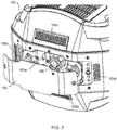
- Figure 3 shows a detail view of the lamp head 102 with the lamp access panel 104 partially removed.
- a lamp 106 mounted within the lamp head 102 may be seen more clearly in Figure 3 .
- No other components of the luminaire obstruct access to the lamp 106 once lamp access panel 104 is removed. There is no need to remove fans, fasteners, cooling ducts, or other hardware prior to removing the lamp 106 from the lamp head 102.
- the cooling system for lamp 106 comprises fans and ducts positioned on the sides, top, bottom, or front of the lamp. Careful design of air ducting and fan vents allows a desired air flow to be maintained across the lamp at all times when it is operating. Five exemplary air ducts, 105a, 105b, 105e, 105d, and 105e are shown in Figure 3 , all positioned out of the removal path of lamp 106.
- Air is drawn into the lamp head 102 through the air ducts 105b, 105c, 105d, and 105e by one or more internal fans and expelled from the air duct 105a towards the lamp 106.
- the air ducts 105b, 105c, 105d, and 105e are all coupled to a common air chamber from which the fan draws air to expel through the air duct 105a.
- additional fans may draw air from one or more of the air ducts 105b, 105c, 105d, and 105e to expel air through additional ducts located elsewhere around the lamp 106.
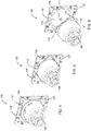
- FIGS 4-6 illustrate a lamp removal and replacement process according to the disclosure for the lamp 106 after the lamp access panel 104 has been removed from the luminaire head 102.
- the lamp 106 is removably mounted in a lamp mounting mechanism 130.
- the lamp mounting mechanism 130 comprises a lamp mounting plate 109.
- a lamp retainer 107 is fixedly attached to the lamp mounting plate 109.
- the lamp mounting mechanism 130 is adjustably mounted to the chassis of the lamp head 102.
- the lamp mounting mechanism 130 is shown in isolation in Figures 4, 5, and 6 , however, as may be seen in Figures 7 and 8 , the lamp mounting mechanism 130 remains mounted in the lamp head 102 during the lamp removal and replacement process shown in Figures 4-7 .
- Removal of the lamp access panel 104 from the luminaire head 102 comprises a first step in the process of lamp removal according to the disclosure.
- Figure 4 illustrates a second step in the process.
- the lamp 106 is retained by four lamp retaining clips 108, which are features of the lamp retainer 107.
- the lamp retainer 107 is formed of spring steel.
- a feature of the lamp mounting plate 109 comprising an inset ring 111 and a shoulder 112 formed by the inset ring 111 provides both mechanical support and positioning for lamp 106.
- the lamp retaining clips 108 extend from the remainder of the lamp retainer 107 over the inset ring 111.
- a front face of the lamp 106 is held firmly against the inset ring 111 by the restorative force of the lamp retaining clips 108, preventing rotation of the lamp 106 relative to the lamp mounting plate 109 through friction.
- a diameter (dimension) of the shoulder 112 is sized to fit the corners 110 and prevent radial movement of the lamp 106 away from a center of the lamp mounting mechanism 130.
- a user grasps the lamp 106 and rotates it axially by hand, as shown by arrow 113.
- the lamp 106 may be rotated in either direction, as shown by arrow 113, until the lamp corners 110 are positioned in openings between the lamp retaining clips 108, in a third step of the lamp removal process as shown in Figure 5 .
- the lamp 106 may be pulled back, as shown by arrow 114, and removed from an aperture 116 in the lamp mounting plate 109, in a fourth step of the lamp removal process as shown in Figure 6 .
- the inset ring 111 and the shoulder 112, described above, may be seen more clearly in Figure 6 .
- Figure 7 illustrates a broader view of the lamp removal process according to the disclosure, showing the fourth step of the process, with the lamp 106 pulled back for replacement after having been released from the lamp retaining clips 108.
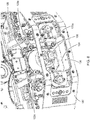
- FIG 8 shows a cutaway drawing of the lamp head 102.
- the lamp mounting mechanism 130 remains mounted in the lamp head 102 during the removal of a lamp 106 and the installation of a new lamp 106.
- the lamp 106 is firmly installed in the lamp mounting mechanism 130.
- the lamp mounting mechanism 130 is mounted in the lamp head 102 by a lamp adjustment mechanism 120 comprising a lamp adjustment plate 124 and adjustment screws 122a, 122b, and 122c.
- the adjustment screws 122a-c pass through respective clearance holes in the lamp adjustment plate 124 and are threaded into threaded holes in three corresponding corners of the lamp mounting plate 109.
- Coaxial springs around each of the adjustment screws 122a-c hold the screws' heads against the lamp adjustment plate 124.
- the center 117 of the lamp mounting plate 109 of the lamp mounting mechanism 130 is aligned with an optical axis of the lamp head 102.
- the optical axis of the lamp 106 may be tilted up and down (in the orientation shown in Figure 8 ).
- the optical axis of the lamp 106 may be tilted left and right.
- the lamp 106 is moved along the optical axis of the lamp head 102 to position the arc of the lamp 106 in a desired position relative a focal point of an optical system of the lamp head 102.
Landscapes
- Engineering & Computer Science (AREA)
- General Engineering & Computer Science (AREA)
- Fastening Of Light Sources Or Lamp Holders (AREA)
- Non-Portable Lighting Devices Or Systems Thereof (AREA)
Claims (15)
- Lampenmontagemechanismus (130) für eine automatisierte Leuchte (100), wobei der Lampenmontagemechanismus Folgendes umfasst:eine Lampenmontageplatte (109) die ein Merkmal umfasst, das konfiguriert ist, um eine Vielzahl von Elementen (110) einer Lampe (106) in Eingriff zu nehmen, wobei die Lampe in dem Lampenmontagemechanismus (130) entfernbar montierbar ist, und, um eine optische Achse der Lampe an einer Mitte der Lampenmontageplatte (109) auszurichten; undeinen Lampenhalter (107), der mit der Lampenmontageplatte (109) gekoppelt ist, wobei der Lampenhalter (107) Folgendes umfasst:eine Vielzahl von Halteklammern (108), wobei die Anzahl der Halteklammern der Anzahl der Elemente (110) der Lampe (106) entspricht;wobei die Halteklammern (108) konfiguriert sind, um Kräfte auf entsprechende der Vielzahl von Elementen (110) der Lampe (106) auszuüben, um die Lampe in einer festen Position relativ zu der Lampenmontageplatte zu halten, wenn die Elemente (110) der Lampe (106) zwischen den Halteklammern (108) und dem Merkmal der Lampenbefestigungsplatte (109) positioniert sind,wobei die Halteklammern (108) ferner konfiguriert sind, um einem Benutzer des Lampenmontagemechanismus (130) zu ermöglichen die Lampe innerhalb des Merkmals der Lampenmontageplatte zu drehen, um die Elemente (110) der Lampe in Öffnungen zwischen den Halteklammern (108) zu positionieren, undwobei die Öffnungen zwischen den Halteklammern (108) konfiguriert sind, um dem Benutzer zu ermöglichen, die Lampe von dem Merkmal der Lampenmontageplatte (109) zu entfernen; dadurch gekennzeichnet, dass die Lampenmontageplatte (109) eine Vielzahl von Gewindebohrungen umfasst, die konfiguriert sind, um Einstellschrauben (122a-c) aufzunehmen, um den Lampenmontagemechanismus (130) in einer automatisierten Leuchte zu montieren.
- Lampenmontagemechanismus (130) nach Anspruch 1, wobei das Merkmal der Lampenmontageplatte (109) einen Einsatzring (111) umfasst und die Halteklammern (108) sich über den Einsatzring erstrecken und konfiguriert sind, um eine Vorderfläche der Lampe (106) gegen eine Fläche des Einsatzrings zu halten.
- Lampenmontagemechanismus (130) nach Anspruch 2, wobei die Elemente der Lampe Überstände sind, die koplanar zu der Vorderfläche der Lampe sind, wobei die Halteklammern (108) und der Einsatzring (111) konfiguriert sind, um die Überstände zwischen den Halteklammern (108) und der Fläche des Einsatzrings (111) aufzunehmen.
- Lampenmontagemechanismus (130) nach Anspruch 1, wobei die Halteklammern (108) gemäß einem oder mehreren von Folgendem angeordnet sind:(i) wobei die Halteklammern (108) Merkmale des Lampenhalters sind;(ii) wobei die Halteklammern (108) Federstahl umfassen;(iii) wobei die Halteklammern (108) separate Elemente sind, die an der Lampenmontageplatte (109) angebracht sind.
- Automatisierte Leuchte (100), die einen Lampenkopf (102) umfasst, wobei der Lampenkopf (102) Folgendes umfasst:eine Lampenzugriffsplatte (104), die an dem Lampenkopf (102) entfernbar montiert und konfiguriert ist, um einen Abschnitt eines Gehäuses des Lampenkopfs auszubilden, wenn sie an dem Lampenkopf montiert ist; undden Lampenmontagemechanismus (130) nach Anspruch 1, der an dem Lampenkopf (102) einstellbar montiert und konfiguriert ist, um für einen Benutzer zugänglich zu sein, wenn die Lampenzugriffsplatte entfernt wird.
- Automatisierte Leuchte (100) nach Anspruch 5, wobei der Lampenkopf (102) ferner einen Lampeneinstellmechanismus (120) umfasst, der konfiguriert ist, um für einen Benutzer zugänglich zu sein, wenn die Lampenzugriffsplatte (104) entfernt wird, wobei der Lampeneinstellmechanismus Folgendes umfasst:eine Lampeneinstellplatte (124), die mit dem Lampenkopf fest gekoppelt ist; undeine Vielzahl von Einstellschrauben (122a), die konfiguriert sind, um in die Vielzahl von Gewindebohrungen einzugreifen, um die Lampenmontageplatte (109) mit der Lampeneinstellplatte (124) einstellbar zu koppeln,wobei der Lampeneinstellmechanismus (120) konfiguriert ist, um eine optische Achse der Lampe an einer optischen Achse des Lampenkopfes (102) auszurichten.
- Automatisierte Leuchte (100) nach Anspruch 6, wobei die Vielzahl von Einstellschrauben (122a-c) konfiguriert sind, um durch eine entsprechende Vielzahl von Durchgangslöchern in der Lampeneinstellplatte (124) zu führen und in entsprechende der Vielzahl von Gewindebohrungen in der Lampenmontageplatte (109) geschraubt zu werden, wobei die Einstellschrauben (122a-c) konfiguriert sind, um eine Position der Lampenmontageplatte (109) entlang der optischen Achse des Lampenkopfs (102) einzustellen.
- Automatisierte Leuchte (100) nach Anspruch 7, wobei eine erste und eine zweite Einstellschraube der Vielzahl von Einstellschrauben (122a-c) konfiguriert sind, um die Lampe in einer ersten Richtung relativ zu dem Lampenkopf zu neigen.
- Automatisierte Leuchte (100) nach Anspruch 8, wobei die zweite und eine dritte Einstellschraube der Vielzahl von Einstellschrauben (122a-c) konfiguriert sind, um die Lampe in einer zweiten Richtung relativ zu dem Lampenkopf (102) zu neigen, wobei die zweite Richtung orthogonal zu der ersten Richtung ist.
- Automatisierte Leuchte (100) nach Anspruch 7, wobei der Lampeneinstellmechanismus (120) ferner eine Vielzahl von Federn umfasst, wobei jede Feder um eine entsprechende der Vielzahl von Einstellschrauben (122a-c) koaxial positioniert und konfiguriert ist, um einen Schraubenkopf der entsprechenden Einstellschraube gegen die Lampeneinstellplatte (124) zu halten.
- Automatisierte Leuchte (100) nach Anspruch 5, wobei das Merkmal der Lampenmontageplatte (109) einen Einsatzring (111) umfasst und wobei die Halteklammern (108) sich über den Einsatzring (111) erstrecken und konfiguriert sind, um eine Vorderfläche der Lampe (106) gegen den Einsatzring zu halten.
- Automatisierte Leuchte (100) nach Anspruch 11, wobei die Elemente der Lampe Überstände sind, die koplanar zu der Vorderfläche der Lampe sind, und die Halteklammern (108) und der Einsatzring (111) konfiguriert sind, um die Überstände zwischen den Halteklammern und einer Fläche des Einsatzrings aufzunehmen.
- Lampenmontagemechanismus (130) nach Anspruch 2, wobei der Einsatzring (111) einen Vorsprung (112) ausbildet und der Vorsprung eine Abmessung aufweist, die konfiguriert ist, um zu den Elementen (110) der Lampe (106) zu passen und, um eine radiale Bewegung der Lampe von einer Ausrichtung mit der Mitte des Lampenmontagemechanismus (130) hinweg zu verhindern.
- Automatisierte Leuchte (100) nach Anspruch 11, wobei der Einsatzring (111) einen Vorsprung (112) ausbildet und der Vorsprung eine Abmessung aufweist, die konfiguriert ist, um zu den Elementen (110) der Lampe (106) zu passen und, um eine radiale Bewegung der Lampe von einer Ausrichtung mit der Mitte des Lampenmontagemechanismus (130) hinweg zu verhindern.
- Automatisierte Leuchte (100) nach Anspruch 6, wobei die Halteklammern (108) gemäß einer oder mehreren von Folgendem angeordnet sind:(i) wobei die Halteklammern Merkmale des Lampenhalters sind;(ii) wobei die Halteklammern Federstahl umfassen;(iii) wobei die Halteklammern separate Elemente sind, die an der Lampenmontageplatte angebracht sind.
Applications Claiming Priority (1)
| Application Number | Priority Date | Filing Date | Title |
|---|---|---|---|
| US201762553727P | 2017-09-01 | 2017-09-01 |
Publications (2)
| Publication Number | Publication Date |
|---|---|
| EP3450840A1 EP3450840A1 (de) | 2019-03-06 |
| EP3450840B1 true EP3450840B1 (de) | 2020-10-14 |
Family
ID=63452550
Family Applications (1)
| Application Number | Title | Priority Date | Filing Date |
|---|---|---|---|
| EP18192012.5A Active EP3450840B1 (de) | 2017-09-01 | 2018-08-31 | Lampenwechselsystem für eine automatisierte leuchte |
Country Status (3)
| Country | Link |
|---|---|
| US (1) | US10539307B2 (de) |
| EP (1) | EP3450840B1 (de) |
| CN (1) | CN109424894B (de) |
Families Citing this family (8)
| Publication number | Priority date | Publication date | Assignee | Title |
|---|---|---|---|---|
| USD930214S1 (en) * | 2020-03-04 | 2021-09-07 | Sgm Light A/S | Stage light |
| CN111594808B (zh) * | 2020-05-29 | 2025-03-28 | 广州市浩洋电子股份有限公司 | 一种低噪音灯具复位结构及其控制方法 |
| USD1035956S1 (en) * | 2022-08-02 | 2024-07-16 | Wuxi AHLights Technology Co., LTD | LED beam pattern moving head light |
| USD1023387S1 (en) * | 2022-09-16 | 2024-04-16 | Xiaozhu Zhang | Stage light |
| USD1036737S1 (en) * | 2022-11-03 | 2024-07-23 | Harman International Industries, Incorporated | Lighting device |
| CN219828640U (zh) * | 2023-02-28 | 2023-10-13 | 广州市浩洋电子股份有限公司 | 一种防止电化学腐蚀的锁紧结构及具有其的舞台灯 |
| USD1120428S1 (en) * | 2024-04-03 | 2026-03-24 | Harman International Industries, Incorporated | Lighting device |
| USD1117883S1 (en) * | 2024-04-15 | 2026-03-10 | Harman International Industries, Incorporated | Lighting device |
Family Cites Families (3)
| Publication number | Priority date | Publication date | Assignee | Title |
|---|---|---|---|---|
| JPH0617003U (ja) | 1992-06-12 | 1994-03-04 | スタンレー電気株式会社 | 車両用前照灯の電球取付部 |
| US6932491B2 (en) * | 2002-11-14 | 2005-08-23 | Electronic Theatre Controls, Inc. | Lamp assembly and lamp for a luminare |
| CN101881392B (zh) | 2010-06-30 | 2013-04-10 | 海洋王照明科技股份有限公司 | 灯具及其反射罩 |
-
2018
- 2018-08-28 US US16/115,077 patent/US10539307B2/en active Active
- 2018-08-31 EP EP18192012.5A patent/EP3450840B1/de active Active
- 2018-09-03 CN CN201811022589.XA patent/CN109424894B/zh active Active
Non-Patent Citations (1)
| Title |
|---|
| None * |
Also Published As
| Publication number | Publication date |
|---|---|
| CN109424894A (zh) | 2019-03-05 |
| US10539307B2 (en) | 2020-01-21 |
| EP3450840A1 (de) | 2019-03-06 |
| US20190056096A1 (en) | 2019-02-21 |
| CN109424894B (zh) | 2021-03-02 |
Similar Documents
| Publication | Publication Date | Title |
|---|---|---|
| EP3450840B1 (de) | Lampenwechselsystem für eine automatisierte leuchte | |
| US11846401B2 (en) | Recessed downlight fixture | |
| EP2388869B1 (de) | Lampe für Theaterleuchte | |
| US7911411B2 (en) | Projection apparatus | |
| US20170284616A1 (en) | Recessed downlight fixture and method for installing and universally adjusting the fixture in a new construction application | |
| JP5757883B2 (ja) | 発光装置及び照明器具 | |
| US10551017B2 (en) | Light control system for a luminaire utilizing a lamp with intense hotspot | |
| CN104302967A (zh) | 用于自动照明设备的变焦光学系统 | |
| US8408755B2 (en) | Stage lighting fixture and method of operating a stage lighting fixture | |
| US10394111B2 (en) | Light Assembly for a projector | |
| US20110103063A1 (en) | Optics for an automated luminaire | |
| EP3715711A1 (de) | Leuchte, vorzugsweise für bühne, und verfahren zum betrieb der besagten leuchte | |
| US6926427B2 (en) | Projector attachment for ellipsoidal lamp | |
| US12595896B2 (en) | Luminaire with a rotating pattern beam | |
| EP1844262B1 (de) | Optisches system für ein washlight | |
| EP2889534B1 (de) | Lampenreflektorsystem mit Rückreflektor | |
| US20160047533A1 (en) | Optics for an automated luminaire | |
| US7682046B2 (en) | Light fixture with lamp adjustment assembly | |
| EP4317769A1 (de) | Gobo projektor und verfahren einer benutzung eines gobo projektors | |
| US7158207B2 (en) | Film projector with high efficiency illumination | |
| US10721806B1 (en) | Auditorium house light positioning system | |
| CN116940786A (zh) | 聚光灯 | |
| US20070063113A1 (en) | Method and apparatus for mounting a lighting device | |
| US20100002446A1 (en) | XYZ control over bulb position in a pan and tilt lamp |
Legal Events
| Date | Code | Title | Description |
|---|---|---|---|
| PUAI | Public reference made under article 153(3) epc to a published international application that has entered the european phase |
Free format text: ORIGINAL CODE: 0009012 |
|
| STAA | Information on the status of an ep patent application or granted ep patent |
Free format text: STATUS: THE APPLICATION HAS BEEN PUBLISHED |
|
| AK | Designated contracting states |
Kind code of ref document: A1 Designated state(s): AL AT BE BG CH CY CZ DE DK EE ES FI FR GB GR HR HU IE IS IT LI LT LU LV MC MK MT NL NO PL PT RO RS SE SI SK SM TR |
|
| AX | Request for extension of the european patent |
Extension state: BA ME |
|
| STAA | Information on the status of an ep patent application or granted ep patent |
Free format text: STATUS: REQUEST FOR EXAMINATION WAS MADE |
|
| 17P | Request for examination filed |
Effective date: 20190819 |
|
| RBV | Designated contracting states (corrected) |
Designated state(s): AL AT BE BG CH CY CZ DE DK EE ES FI FR GB GR HR HU IE IS IT LI LT LU LV MC MK MT NL NO PL PT RO RS SE SI SK SM TR |
|
| RIC1 | Information provided on ipc code assigned before grant |
Ipc: F21V 19/02 20060101ALI20200214BHEP Ipc: F21W 131/406 20060101ALN20200214BHEP Ipc: F21V 19/04 20060101AFI20200214BHEP |
|
| GRAP | Despatch of communication of intention to grant a patent |
Free format text: ORIGINAL CODE: EPIDOSNIGR1 |
|
| STAA | Information on the status of an ep patent application or granted ep patent |
Free format text: STATUS: GRANT OF PATENT IS INTENDED |
|
| INTG | Intention to grant announced |
Effective date: 20200402 |
|
| GRAJ | Information related to disapproval of communication of intention to grant by the applicant or resumption of examination proceedings by the epo deleted |
Free format text: ORIGINAL CODE: EPIDOSDIGR1 |
|
| STAA | Information on the status of an ep patent application or granted ep patent |
Free format text: STATUS: REQUEST FOR EXAMINATION WAS MADE |
|
| GRAR | Information related to intention to grant a patent recorded |
Free format text: ORIGINAL CODE: EPIDOSNIGR71 |
|
| GRAS | Grant fee paid |
Free format text: ORIGINAL CODE: EPIDOSNIGR3 |
|
| STAA | Information on the status of an ep patent application or granted ep patent |
Free format text: STATUS: GRANT OF PATENT IS INTENDED |
|
| INTC | Intention to grant announced (deleted) | ||
| GRAA | (expected) grant |
Free format text: ORIGINAL CODE: 0009210 |
|
| STAA | Information on the status of an ep patent application or granted ep patent |
Free format text: STATUS: THE PATENT HAS BEEN GRANTED |
|
| INTG | Intention to grant announced |
Effective date: 20200902 |
|
| RIC1 | Information provided on ipc code assigned before grant |
Ipc: F21V 19/02 20060101ALI20200828BHEP Ipc: F21W 131/406 20060101ALN20200828BHEP Ipc: F21V 19/04 20060101AFI20200828BHEP |
|
| AK | Designated contracting states |
Kind code of ref document: B1 Designated state(s): AL AT BE BG CH CY CZ DE DK EE ES FI FR GB GR HR HU IE IS IT LI LT LU LV MC MK MT NL NO PL PT RO RS SE SI SK SM TR |
|
| REG | Reference to a national code |
Ref country code: GB Ref legal event code: FG4D |
|
| REG | Reference to a national code |
Ref country code: AT Ref legal event code: REF Ref document number: 1323945 Country of ref document: AT Kind code of ref document: T Effective date: 20201015 Ref country code: CH Ref legal event code: EP |
|
| REG | Reference to a national code |
Ref country code: DE Ref legal event code: R096 Ref document number: 602018008668 Country of ref document: DE |
|
| REG | Reference to a national code |
Ref country code: IE Ref legal event code: FG4D |
|
| REG | Reference to a national code |
Ref country code: NL Ref legal event code: FP |
|
| REG | Reference to a national code |
Ref country code: AT Ref legal event code: MK05 Ref document number: 1323945 Country of ref document: AT Kind code of ref document: T Effective date: 20201014 |
|
| PG25 | Lapsed in a contracting state [announced via postgrant information from national office to epo] |
Ref country code: FI Free format text: LAPSE BECAUSE OF FAILURE TO SUBMIT A TRANSLATION OF THE DESCRIPTION OR TO PAY THE FEE WITHIN THE PRESCRIBED TIME-LIMIT Effective date: 20201014 Ref country code: RS Free format text: LAPSE BECAUSE OF FAILURE TO SUBMIT A TRANSLATION OF THE DESCRIPTION OR TO PAY THE FEE WITHIN THE PRESCRIBED TIME-LIMIT Effective date: 20201014 Ref country code: PT Free format text: LAPSE BECAUSE OF FAILURE TO SUBMIT A TRANSLATION OF THE DESCRIPTION OR TO PAY THE FEE WITHIN THE PRESCRIBED TIME-LIMIT Effective date: 20210215 Ref country code: GR Free format text: LAPSE BECAUSE OF FAILURE TO SUBMIT A TRANSLATION OF THE DESCRIPTION OR TO PAY THE FEE WITHIN THE PRESCRIBED TIME-LIMIT Effective date: 20210115 Ref country code: NO Free format text: LAPSE BECAUSE OF FAILURE TO SUBMIT A TRANSLATION OF THE DESCRIPTION OR TO PAY THE FEE WITHIN THE PRESCRIBED TIME-LIMIT Effective date: 20210114 |
|
| REG | Reference to a national code |
Ref country code: LT Ref legal event code: MG4D |
|
| PG25 | Lapsed in a contracting state [announced via postgrant information from national office to epo] |
Ref country code: IS Free format text: LAPSE BECAUSE OF FAILURE TO SUBMIT A TRANSLATION OF THE DESCRIPTION OR TO PAY THE FEE WITHIN THE PRESCRIBED TIME-LIMIT Effective date: 20210214 Ref country code: PL Free format text: LAPSE BECAUSE OF FAILURE TO SUBMIT A TRANSLATION OF THE DESCRIPTION OR TO PAY THE FEE WITHIN THE PRESCRIBED TIME-LIMIT Effective date: 20201014 Ref country code: LV Free format text: LAPSE BECAUSE OF FAILURE TO SUBMIT A TRANSLATION OF THE DESCRIPTION OR TO PAY THE FEE WITHIN THE PRESCRIBED TIME-LIMIT Effective date: 20201014 Ref country code: SE Free format text: LAPSE BECAUSE OF FAILURE TO SUBMIT A TRANSLATION OF THE DESCRIPTION OR TO PAY THE FEE WITHIN THE PRESCRIBED TIME-LIMIT Effective date: 20201014 Ref country code: BG Free format text: LAPSE BECAUSE OF FAILURE TO SUBMIT A TRANSLATION OF THE DESCRIPTION OR TO PAY THE FEE WITHIN THE PRESCRIBED TIME-LIMIT Effective date: 20210114 Ref country code: ES Free format text: LAPSE BECAUSE OF FAILURE TO SUBMIT A TRANSLATION OF THE DESCRIPTION OR TO PAY THE FEE WITHIN THE PRESCRIBED TIME-LIMIT Effective date: 20201014 Ref country code: AT Free format text: LAPSE BECAUSE OF FAILURE TO SUBMIT A TRANSLATION OF THE DESCRIPTION OR TO PAY THE FEE WITHIN THE PRESCRIBED TIME-LIMIT Effective date: 20201014 |
|
| PG25 | Lapsed in a contracting state [announced via postgrant information from national office to epo] |
Ref country code: HR Free format text: LAPSE BECAUSE OF FAILURE TO SUBMIT A TRANSLATION OF THE DESCRIPTION OR TO PAY THE FEE WITHIN THE PRESCRIBED TIME-LIMIT Effective date: 20201014 |
|
| REG | Reference to a national code |
Ref country code: DE Ref legal event code: R097 Ref document number: 602018008668 Country of ref document: DE |
|
| PG25 | Lapsed in a contracting state [announced via postgrant information from national office to epo] |
Ref country code: LT Free format text: LAPSE BECAUSE OF FAILURE TO SUBMIT A TRANSLATION OF THE DESCRIPTION OR TO PAY THE FEE WITHIN THE PRESCRIBED TIME-LIMIT Effective date: 20201014 Ref country code: SK Free format text: LAPSE BECAUSE OF FAILURE TO SUBMIT A TRANSLATION OF THE DESCRIPTION OR TO PAY THE FEE WITHIN THE PRESCRIBED TIME-LIMIT Effective date: 20201014 Ref country code: RO Free format text: LAPSE BECAUSE OF FAILURE TO SUBMIT A TRANSLATION OF THE DESCRIPTION OR TO PAY THE FEE WITHIN THE PRESCRIBED TIME-LIMIT Effective date: 20201014 Ref country code: CZ Free format text: LAPSE BECAUSE OF FAILURE TO SUBMIT A TRANSLATION OF THE DESCRIPTION OR TO PAY THE FEE WITHIN THE PRESCRIBED TIME-LIMIT Effective date: 20201014 Ref country code: EE Free format text: LAPSE BECAUSE OF FAILURE TO SUBMIT A TRANSLATION OF THE DESCRIPTION OR TO PAY THE FEE WITHIN THE PRESCRIBED TIME-LIMIT Effective date: 20201014 Ref country code: SM Free format text: LAPSE BECAUSE OF FAILURE TO SUBMIT A TRANSLATION OF THE DESCRIPTION OR TO PAY THE FEE WITHIN THE PRESCRIBED TIME-LIMIT Effective date: 20201014 |
|
| PLBE | No opposition filed within time limit |
Free format text: ORIGINAL CODE: 0009261 |
|
| STAA | Information on the status of an ep patent application or granted ep patent |
Free format text: STATUS: NO OPPOSITION FILED WITHIN TIME LIMIT |
|
| PG25 | Lapsed in a contracting state [announced via postgrant information from national office to epo] |
Ref country code: DK Free format text: LAPSE BECAUSE OF FAILURE TO SUBMIT A TRANSLATION OF THE DESCRIPTION OR TO PAY THE FEE WITHIN THE PRESCRIBED TIME-LIMIT Effective date: 20201014 |
|
| 26N | No opposition filed |
Effective date: 20210715 |
|
| PG25 | Lapsed in a contracting state [announced via postgrant information from national office to epo] |
Ref country code: IT Free format text: LAPSE BECAUSE OF FAILURE TO SUBMIT A TRANSLATION OF THE DESCRIPTION OR TO PAY THE FEE WITHIN THE PRESCRIBED TIME-LIMIT Effective date: 20201014 Ref country code: AL Free format text: LAPSE BECAUSE OF FAILURE TO SUBMIT A TRANSLATION OF THE DESCRIPTION OR TO PAY THE FEE WITHIN THE PRESCRIBED TIME-LIMIT Effective date: 20201014 |
|
| PG25 | Lapsed in a contracting state [announced via postgrant information from national office to epo] |
Ref country code: SI Free format text: LAPSE BECAUSE OF FAILURE TO SUBMIT A TRANSLATION OF THE DESCRIPTION OR TO PAY THE FEE WITHIN THE PRESCRIBED TIME-LIMIT Effective date: 20201014 |
|
| REG | Reference to a national code |
Ref country code: CH Ref legal event code: PL |
|
| PG25 | Lapsed in a contracting state [announced via postgrant information from national office to epo] |
Ref country code: MC Free format text: LAPSE BECAUSE OF FAILURE TO SUBMIT A TRANSLATION OF THE DESCRIPTION OR TO PAY THE FEE WITHIN THE PRESCRIBED TIME-LIMIT Effective date: 20201014 |
|
| REG | Reference to a national code |
Ref country code: BE Ref legal event code: MM Effective date: 20210831 |
|
| PG25 | Lapsed in a contracting state [announced via postgrant information from national office to epo] |
Ref country code: LI Free format text: LAPSE BECAUSE OF NON-PAYMENT OF DUE FEES Effective date: 20210831 Ref country code: CH Free format text: LAPSE BECAUSE OF NON-PAYMENT OF DUE FEES Effective date: 20210831 |
|
| PG25 | Lapsed in a contracting state [announced via postgrant information from national office to epo] |
Ref country code: IS Free format text: LAPSE BECAUSE OF FAILURE TO SUBMIT A TRANSLATION OF THE DESCRIPTION OR TO PAY THE FEE WITHIN THE PRESCRIBED TIME-LIMIT Effective date: 20210214 Ref country code: LU Free format text: LAPSE BECAUSE OF NON-PAYMENT OF DUE FEES Effective date: 20210831 |
|
| PG25 | Lapsed in a contracting state [announced via postgrant information from national office to epo] |
Ref country code: IE Free format text: LAPSE BECAUSE OF NON-PAYMENT OF DUE FEES Effective date: 20210831 Ref country code: BE Free format text: LAPSE BECAUSE OF NON-PAYMENT OF DUE FEES Effective date: 20210831 |
|
| P01 | Opt-out of the competence of the unified patent court (upc) registered |
Effective date: 20230523 |
|
| PG25 | Lapsed in a contracting state [announced via postgrant information from national office to epo] |
Ref country code: CY Free format text: LAPSE BECAUSE OF FAILURE TO SUBMIT A TRANSLATION OF THE DESCRIPTION OR TO PAY THE FEE WITHIN THE PRESCRIBED TIME-LIMIT Effective date: 20201014 |
|
| PG25 | Lapsed in a contracting state [announced via postgrant information from national office to epo] |
Ref country code: HU Free format text: LAPSE BECAUSE OF FAILURE TO SUBMIT A TRANSLATION OF THE DESCRIPTION OR TO PAY THE FEE WITHIN THE PRESCRIBED TIME-LIMIT; INVALID AB INITIO Effective date: 20180831 |
|
| PG25 | Lapsed in a contracting state [announced via postgrant information from national office to epo] |
Ref country code: MK Free format text: LAPSE BECAUSE OF FAILURE TO SUBMIT A TRANSLATION OF THE DESCRIPTION OR TO PAY THE FEE WITHIN THE PRESCRIBED TIME-LIMIT Effective date: 20201014 |
|
| PG25 | Lapsed in a contracting state [announced via postgrant information from national office to epo] |
Ref country code: TR Free format text: LAPSE BECAUSE OF FAILURE TO SUBMIT A TRANSLATION OF THE DESCRIPTION OR TO PAY THE FEE WITHIN THE PRESCRIBED TIME-LIMIT Effective date: 20201014 |
|
| PG25 | Lapsed in a contracting state [announced via postgrant information from national office to epo] |
Ref country code: MT Free format text: LAPSE BECAUSE OF FAILURE TO SUBMIT A TRANSLATION OF THE DESCRIPTION OR TO PAY THE FEE WITHIN THE PRESCRIBED TIME-LIMIT Effective date: 20201014 |
|
| PGFP | Annual fee paid to national office [announced via postgrant information from national office to epo] |
Ref country code: NL Payment date: 20250723 Year of fee payment: 8 |
|
| PGFP | Annual fee paid to national office [announced via postgrant information from national office to epo] |
Ref country code: DE Payment date: 20250724 Year of fee payment: 8 |
|
| PGFP | Annual fee paid to national office [announced via postgrant information from national office to epo] |
Ref country code: GB Payment date: 20250724 Year of fee payment: 8 |
|
| PGFP | Annual fee paid to national office [announced via postgrant information from national office to epo] |
Ref country code: FR Payment date: 20250725 Year of fee payment: 8 |