EP3705634B1 - Ventil für die trinkwasserinstallation - Google Patents
Ventil für die trinkwasserinstallation Download PDFInfo
- Publication number
- EP3705634B1 EP3705634B1 EP20160663.9A EP20160663A EP3705634B1 EP 3705634 B1 EP3705634 B1 EP 3705634B1 EP 20160663 A EP20160663 A EP 20160663A EP 3705634 B1 EP3705634 B1 EP 3705634B1
- Authority
- EP
- European Patent Office
- Prior art keywords
- regulating piston
- valve
- housing
- regulating
- spindle
- Prior art date
- Legal status (The legal status is an assumption and is not a legal conclusion. Google has not performed a legal analysis and makes no representation as to the accuracy of the status listed.)
- Active
Links
Images




Classifications
-
- F—MECHANICAL ENGINEERING; LIGHTING; HEATING; WEAPONS; BLASTING
- F16—ENGINEERING ELEMENTS AND UNITS; GENERAL MEASURES FOR PRODUCING AND MAINTAINING EFFECTIVE FUNCTIONING OF MACHINES OR INSTALLATIONS; THERMAL INSULATION IN GENERAL
- F16K—VALVES; TAPS; COCKS; ACTUATING-FLOATS; DEVICES FOR VENTING OR AERATING
- F16K1/00—Lift valves or globe valves, i.e. cut-off apparatus with closure members having at least a component of their opening and closing motion perpendicular to the closing faces
- F16K1/32—Details
- F16K1/52—Means for additional adjustment of the rate of flow
-
- E—FIXED CONSTRUCTIONS
- E03—WATER SUPPLY; SEWERAGE
- E03B—INSTALLATIONS OR METHODS FOR OBTAINING, COLLECTING, OR DISTRIBUTING WATER
- E03B7/00—Water main or service pipe systems
- E03B7/07—Arrangement of devices, e.g. filters, flow controls, measuring devices, siphons or valves, in the pipe systems
-
- F—MECHANICAL ENGINEERING; LIGHTING; HEATING; WEAPONS; BLASTING
- F16—ENGINEERING ELEMENTS AND UNITS; GENERAL MEASURES FOR PRODUCING AND MAINTAINING EFFECTIVE FUNCTIONING OF MACHINES OR INSTALLATIONS; THERMAL INSULATION IN GENERAL
- F16K—VALVES; TAPS; COCKS; ACTUATING-FLOATS; DEVICES FOR VENTING OR AERATING
- F16K31/00—Actuating devices; Operating means; Releasing devices
- F16K31/02—Actuating devices; Operating means; Releasing devices electric; magnetic
- F16K31/04—Actuating devices; Operating means; Releasing devices electric; magnetic using a motor
-
- E—FIXED CONSTRUCTIONS
- E03—WATER SUPPLY; SEWERAGE
- E03C—DOMESTIC PLUMBING INSTALLATIONS FOR FRESH WATER OR WASTE WATER; SINKS
- E03C1/00—Domestic plumbing installations for fresh water or waste water; Sinks
- E03C1/02—Plumbing installations for fresh water
- E03C1/10—Devices for preventing contamination of drinking-water pipes, e.g. means for aerating self-closing flushing valves
-
- F—MECHANICAL ENGINEERING; LIGHTING; HEATING; WEAPONS; BLASTING
- F16—ENGINEERING ELEMENTS AND UNITS; GENERAL MEASURES FOR PRODUCING AND MAINTAINING EFFECTIVE FUNCTIONING OF MACHINES OR INSTALLATIONS; THERMAL INSULATION IN GENERAL
- F16K—VALVES; TAPS; COCKS; ACTUATING-FLOATS; DEVICES FOR VENTING OR AERATING
- F16K1/00—Lift valves or globe valves, i.e. cut-off apparatus with closure members having at least a component of their opening and closing motion perpendicular to the closing faces
- F16K1/32—Details
-
- F—MECHANICAL ENGINEERING; LIGHTING; HEATING; WEAPONS; BLASTING
- F16—ENGINEERING ELEMENTS AND UNITS; GENERAL MEASURES FOR PRODUCING AND MAINTAINING EFFECTIVE FUNCTIONING OF MACHINES OR INSTALLATIONS; THERMAL INSULATION IN GENERAL
- F16K—VALVES; TAPS; COCKS; ACTUATING-FLOATS; DEVICES FOR VENTING OR AERATING
- F16K1/00—Lift valves or globe valves, i.e. cut-off apparatus with closure members having at least a component of their opening and closing motion perpendicular to the closing faces
- F16K1/32—Details
- F16K1/34—Cutting-off parts, e.g. valve members, seats
- F16K1/36—Valve members
-
- F—MECHANICAL ENGINEERING; LIGHTING; HEATING; WEAPONS; BLASTING
- F16—ENGINEERING ELEMENTS AND UNITS; GENERAL MEASURES FOR PRODUCING AND MAINTAINING EFFECTIVE FUNCTIONING OF MACHINES OR INSTALLATIONS; THERMAL INSULATION IN GENERAL
- F16K—VALVES; TAPS; COCKS; ACTUATING-FLOATS; DEVICES FOR VENTING OR AERATING
- F16K17/00—Safety valves; Equalising valves, e.g. pressure relief valves
- F16K17/02—Safety valves; Equalising valves, e.g. pressure relief valves opening on surplus pressure on one side; closing on insufficient pressure on one side
- F16K17/04—Safety valves; Equalising valves, e.g. pressure relief valves opening on surplus pressure on one side; closing on insufficient pressure on one side spring-loaded
- F16K17/042—Safety valves; Equalising valves, e.g. pressure relief valves opening on surplus pressure on one side; closing on insufficient pressure on one side spring-loaded with locking or disconnecting arrangements
-
- F—MECHANICAL ENGINEERING; LIGHTING; HEATING; WEAPONS; BLASTING
- F16—ENGINEERING ELEMENTS AND UNITS; GENERAL MEASURES FOR PRODUCING AND MAINTAINING EFFECTIVE FUNCTIONING OF MACHINES OR INSTALLATIONS; THERMAL INSULATION IN GENERAL
- F16K—VALVES; TAPS; COCKS; ACTUATING-FLOATS; DEVICES FOR VENTING OR AERATING
- F16K27/00—Construction of housing; Use of materials therefor
- F16K27/02—Construction of housing; Use of materials therefor of lift valves
-
- F—MECHANICAL ENGINEERING; LIGHTING; HEATING; WEAPONS; BLASTING
- F16—ENGINEERING ELEMENTS AND UNITS; GENERAL MEASURES FOR PRODUCING AND MAINTAINING EFFECTIVE FUNCTIONING OF MACHINES OR INSTALLATIONS; THERMAL INSULATION IN GENERAL
- F16K—VALVES; TAPS; COCKS; ACTUATING-FLOATS; DEVICES FOR VENTING OR AERATING
- F16K31/00—Actuating devices; Operating means; Releasing devices
- F16K31/002—Actuating devices; Operating means; Releasing devices actuated by temperature variation
-
- F—MECHANICAL ENGINEERING; LIGHTING; HEATING; WEAPONS; BLASTING
- F16—ENGINEERING ELEMENTS AND UNITS; GENERAL MEASURES FOR PRODUCING AND MAINTAINING EFFECTIVE FUNCTIONING OF MACHINES OR INSTALLATIONS; THERMAL INSULATION IN GENERAL
- F16K—VALVES; TAPS; COCKS; ACTUATING-FLOATS; DEVICES FOR VENTING OR AERATING
- F16K31/00—Actuating devices; Operating means; Releasing devices
- F16K31/02—Actuating devices; Operating means; Releasing devices electric; magnetic
- F16K31/04—Actuating devices; Operating means; Releasing devices electric; magnetic using a motor
- F16K31/046—Actuating devices; Operating means; Releasing devices electric; magnetic using a motor with electric means, e.g. electric switches, to control the motor or to control a clutch between the valve and the motor
-
- F—MECHANICAL ENGINEERING; LIGHTING; HEATING; WEAPONS; BLASTING
- F16—ENGINEERING ELEMENTS AND UNITS; GENERAL MEASURES FOR PRODUCING AND MAINTAINING EFFECTIVE FUNCTIONING OF MACHINES OR INSTALLATIONS; THERMAL INSULATION IN GENERAL
- F16K—VALVES; TAPS; COCKS; ACTUATING-FLOATS; DEVICES FOR VENTING OR AERATING
- F16K41/00—Spindle sealings
- F16K41/02—Spindle sealings with stuffing-box ; Sealing rings
-
- E—FIXED CONSTRUCTIONS
- E03—WATER SUPPLY; SEWERAGE
- E03B—INSTALLATIONS OR METHODS FOR OBTAINING, COLLECTING, OR DISTRIBUTING WATER
- E03B7/00—Water main or service pipe systems
- E03B7/04—Domestic or like local pipe systems
- E03B7/045—Domestic or like local pipe systems diverting initially cold water in warm water supply
Definitions
- the present invention relates to a valve for drinking water installations according to the preamble features of claim 1.
- a valve is made of EN 10 2011 010 840 A1 known.
- the present invention relates in particular to a valve for regulating cold water circulation.
- a flow path for the drinking water is formed in the valve housing, in which a thermal expansion element is exposed, which is placed against a regulating piston under the pretension of a spring element. The expansion of the expansion element moves the regulating piston relative to a bore. This results in temperature-controlled regulation of the flow through the valve.
- This flow through the valve is carried out with the aim of setting a Kv min for drinking water with a low temperature, so that only minimal circulation occurs when the drinking water is sufficiently cold.
- the circulation through the valve should be increased in order to discharge the warm drinking water as quickly as possible from the line section assigned to the valve and to supply it with cooling via a circulation line, which is usually provided with a pump, as is the case, for example, in EP 2 487 301 B1
- a circulation line which is usually provided with a pump
- the EN 10 2011 010 840 A1 The previously known valve for controlling cold water circulation still leaves something to be desired.
- the solution described there corresponds to a conventional valve for regulating hot water circulation, which has been known for a long time, with the only difference being that the behavior of the expansion element is used in such a way that the flow passage is increased as the water temperature increases and not reduced as with thermal regulating valves for hot water circulation. Otherwise, the design principles of hot water regulating valves are adopted identically. However, these do not adequately meet the requirements of circulation in a cold water system.
- the present invention is based on the problem of specifying an improved valve for drinking water installations which, depending on an adjustable or fixed temperature, allows a larger volume flow of cold water at a water temperature that is higher than this temperature and preferably regulates the flow to a minimum volume flow at a low temperature.
- the present invention proposes a valve with the features of claim 1.
- An alternative solution is specified in claim 5. Both aspects in combination result in a valve that is optimally adapted for cold water circulation.
- the valve can set a very low volume flow at Kv Min of approximately 0.05 m 3 /h +/- 0.01 m 3 /h.
- the regulating gap is not designed as an annular gap in the circumferential direction. Rather, between the outer circumferential surface of the regulating piston and the bore, which is usually fixed to the housing, there is a radially extending gap that is not continuous around the circumference. A Kv min flow passage is formed through this gap. The flow passage is formed when the regulating piston with its Kv min adjustment range is at the level of the bore. This position of the Kv min adjustment range is referred to as the Kv min position.
- a very small Kv min flow passage is formed by a single radially extending gap.
- several radially extending gaps can also be provided, each of which is not continuous in the circumferential direction.
- the gap usually extends by a few degrees in the circumferential direction, for example by between 2 and 8°.
- the Kv min adjustment range of the regulating piston is formed by a certain area of the piston extending in the axial direction, which lies within the bore in the Kv min position.
- the regulating piston Adjacent to the Kv min setting range, the regulating piston usually forms an outer peripheral surface that allows cold water to pass through the regulating gap as the drinking water heats up and the expansion element expands. This increases the flow passage between the regulating piston and the bore in order to drain away warm, stale water.
- the regulating piston usually has a plastic sealing element in its Kv min setting range, the outer circumferential surface of which defines the gap in the Kv min position of the regulating piston.
- This plastic sealing element can be fixed with its outer circumferential surface at least partially to a bore defining the bore, usually provided fixed to the housing. Counter surface and seal the regulating gap at least predominantly circumferentially. A seal of at least 330°, preferably at least 350° of the circumferential extent of the bore is considered to be at least predominantly circumferential sealing.
- the regulating piston has a plastic sealing element in its Kv min adjustment range, which has a radial slot that forms the regulating gap in the Kv min position of the regulating piston.
- This plastic sealing element can bear against the counter surface with radial preload.
- a support surface supporting the sealing element which can be formed by a regulating piston base and/or the inner circumferential surface of the bore can be conical, so that as the Kv min position is approached, the annular plastic sealing element is compressed in the slot area and the flow passage is narrowed. It should not be possible to achieve a position adjustable by the expansion element in which the flow passage is completely blocked or made impossible.
- the latter also has a Kv max setting range.
- Kv max setting range of the regulating piston support points are formed on the outer circumferential surface of the regulating piston. Flow passage troughs are located between these support points. Accordingly, support points and flow passage troughs alternate in the circumferential direction at the level of the Kv max setting range.
- the support points In a Kv max position of the regulating piston, the support points extend to the bore. This results in guidance and support of the piston in the Kv max position.
- the spring element for bracing the regulating piston in the direction of the spindle with the interposition of the expansion element is usually considerably compressed in the Kv max position and the regulating piston is only inadequately guided axially relative to the spindle directly or indirectly via the expansion element and is only supported directly or indirectly on the front side.
- the support points thus provide a certain guidance of the regulating piston in the Kv max position.
- the support points do not have to be designed in the manner of a fit.
- the support points can define an envelope surface that is slightly smaller than the inner peripheral surface of the bore. However, at least two support points usually rest on the counter surface defined by the bore, so that the regulating piston in the Kv max position is supported and guided by the housing that usually defines the bore.
- the Kv max setting range is located on the regulating piston between the Kv min setting range and the spindle.
- the regulating piston accordingly first forms the Kv max setting range, then a regulating setting range for regulating the flow passage due to the expansion of the expansion element and a Kv min setting range for setting the Kv min flow passage.
- This setting range usually also indicates the highest position of the regulating piston as part of its movement within the valve housing. In this highest position, the regulating piston is as close as possible to a head of the valve through which the spindle extends. The distance at the bottom is accordingly greatest in the highest position.
- the spindle is rotatably mounted in a valve insert housing.
- This valve insert housing forms at least one first radial flow passage leading to the expansion element.
- This first radial flow passage can be an inlet opening or outlet opening to a flow path within the valve insert housing in which the expansion element is exposed.
- the valve insert housing is connected to an inlet sleeve, which is usually sealingly connected to the valve insert housing, is usually screwed, and forms a second radial flow passage, which is formed by the other of the inlet and outlet openings to the flow path.
- the inlet sleeve preferably forms the inlet of the flow to the expansion element.
- the inlet sleeve also forms a base on which the spring element is supported with its free lower end.
- the inlet sleeve preferably forms a support collar on which the spring element is supported on the inside.
- the spring is a coil spring.
- the support collar prevents the spring element from buckling and guides the coil spring on the outside.
- the support collar is preferably formed by a spring support sleeve which is held axially movable relative to the valve insert housing, preferably held axially movable within limits within the inlet sleeve.
- the inlet sleeve forms at least one end stop against which the spring support sleeve rests prior to assembly due to the preload of the spring element, so that the valve insert housing together with the inlet sleeve and the spring support sleeve can be handled as a unit and screwed into the valve housing.
- the spring support sleeve is supported on the valve housing in the installation situation. This avoids dead spaces and the like that could arise between the bottom of the inlet sleeve, which is closed on the underside, and the opposite wall that forms the valve housing.
- a valve plate which carries a sealing disk which, in a closed position of the valve, rests against a sealing seat provided adjacent to the bore.
- the valve plate preferably supports the expansion element.
- the valve plate is accordingly located between the spindle and the expansion element and is usually preferably directly contacted by the spindle-side end of the expansion element.
- a motor drive is provided which is operatively connected to the spindle.
- This motor drive is particularly suitable for setting Kv max.
- Kv max of the valve according to the invention allows in particular flushing of the line sections assigned to the valve.
- Kv max is set in such a way that a volume flow of 1.8 m 3 /h +/- 0.5 m 3 /h can be set at the usual system pressures.
- Such a control characteristic cannot be set solely by expanding the expansion element.
- Kv max in the valve according to the invention is preferably set by the motor drive. For this purpose, this has a control which contains a memory in which at least one predetermined flushing regime is stored.
- the control is set up in such a way that the motor drive moves the regulating piston from a preset regulating position to the Kv max position for flushing, preferably pushing it axially in the manner of a tappet.
- the preset regulating position is a position of the regulating piston in which the regulating setting range or the Kv min setting range is within the bore.
- the control is also set so that after flushing is complete, the regulating piston is returned to the preset regulating position by the motor drive.
- the motor drive acts The drive is usually connected to the spindle, which can be rotated and adjusted independently of the motor and manually.
- the motor drive, the control and the memory are preferably accommodated in a uniform drive housing, preferably connected to the valve housing in a rotationally fixed manner.
- the connection between the valve housing and such a drive can, for example, be made according to the patent application attributable to the present applicant. EN 20 2006 013 186 U1 take place.
- the regulating body is axially movable within limits in the housing-side bore in the Kv min setting range while maintaining a constant volume flow.
- the Kv min flow passage accordingly has a constant flow cross-section over a certain axial extent. The same applies to the Kv max setting range and the Kv max flow passage.
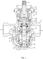
- the Figure 1 shows an embodiment of a valve with a valve housing 2, which forms an inlet opening 4 and an outlet opening 6.
- a partition wall 8 is provided, which defines a bore into which a valve insert 10 is sealingly inserted.
- the valve insert 10 has a valve insert housing 12 in which a spindle 14 is rotatably mounted, which is mounted via a regulating upper part 16, which is screwed to the valve insert housing 12.
- the regulating upper part 16 has projections that overlap part of the spindle 14 and accordingly fix the spindle 14 axially relative to the valve upper part 16.
- the valve upper part 16 is screwed inside the valve insert housing 12 and can be adjusted there, whereby a pre-setting of the spindle 14 is possible.
- the spindle 14 is a non-rising spindle that engages with an adjusting element 18, which on the opposite side interacts with a valve plate 20, which engages with a cam in a recess of the adjusting element 18.
- the valve plate 20 On the underside opposite the adjusting element 18, the valve plate 20 has a sealing disk 22 that circumferentially surrounds an expansion element 24.
- the expansion element 24 has a central pin that engages in a correspondingly designed, slightly conical insert bore of the valve plate 20.
- the expansion element 24 has a contact collar 26, against which a regulating piston 28 rests.
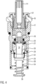
- This regulating piston 28 consists of a metallic regulating piston base 30 and a plastic sealing element 32 made of plastic, see. Figure 4 .
- a spring element 34 rests against the expansion element 24 under prestress.
- the other end of the spring element 34 rests on a contact surface 36 of an inlet sleeve identified by reference numeral 38.
- This inlet sleeve 38 defines opposing valve insert inlet openings 40 through which the cold water to be regulated reaches the expansion element 24.
- Reference numeral 42 indicates valve insert outlet openings through which the flow flows out of the valve insert 10.
- the inlet sleeve 38 is screwed to the valve insert housing 12. A seal seals the screw connection. At its lower end, the inlet sleeve 38 has another sealing ring which seals the valve insert 10 against the hole cut out in the partition wall 8. In the embodiment according to Figure 1 the inlet sleeve 38 is formed on the valve insert housing 12 as a segment of a unitary component.
- the spring element 34 is supported on the underside on a spring support sleeve 44, which is provided with at least two opposing holes on its outer circumference to avoid dead spaces. These holes are located in the area of a support collar 46, which supports the spring element 34, which is designed as a helical spring, all around.
- the support collar 46 projects over a support ring 48, against which the spring element 34 rests at the end and which forms a locking projection that projects radially outwards, which is axially movable and is limited in its downward movement by a stop.
- the spring support sleeve 44 can thus be moved axially relative to the valve insert 10 within limits.
- this mobility is used to support and attach the spring support sleeve 44 to the valve housing 2 when the valve insert 10 is installed.
- the spring support sleeve 44 can be open on the underside or - as Figure 2 clarified - be closed on the underside.
- the support collar 46 has an inner diameter which is adapted to receive the free end of the expansion element 24.
- an adjustment wheel 50 which is provided in a rotationally fixed manner with the adjusting element 18 and which interacts with a scale 52 in order to preset a Kv min value and to display the preset value via the scale 52, which is rotated relative to the spindle provided with a corresponding marking during the presetting.
- the adjustment wheel 50 can also be used as a motor adapter for a drive unit which adjusts the spindle 14.
- the Figure 4 shows a comparison with the embodiment according to the Figures 1 to 3 slightly modified embodiment. This essentially differs only in the design of a base 36 that forms the contact surface for the spring element, which is flat here and does not interact with the valve housing 2 in the installation situation. Identical components are identified with the same reference numerals as in the previously discussed embodiment.
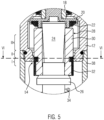
- the Figure 5 shows the regulating piston 28 in its Kv min position and also applies to the first embodiment.
- the outer circumferential surface of the plastic sealing element 32 acts as an almost complete circumferential seal in a bore 54 defined by the valve insert housing 12.
- Figure 6 shows flow passages for a first variant, identified with reference number 56, which are formed by radial notches 58 within the bore 54.
- the notches 58 extend in the radial direction, but only have a small circumferential extent.
- the plastic sealing element 32 is circumferentially closed in this variant.
- the Figures 5 , 6 and 7 show the configuration of the regulating piston 28 and bore 54 in the Kv min position.
- the flow passage 56 is not formed circumferentially between the bore 54 and the regulating piston 28. Rather, only at least one discrete section in the circumferential direction is provided, which allows a flow to pass through. Otherwise, the plastic sealing element 32 lies essentially completely against the inner circumferential surface of the predominantly circular bore 54.
- the Kv min setting range formed by the regulating piston 28 in the previously described position is in Figure 5 marked with I.
- the regulating piston 28 forms a Kv max adjustment range, which is marked with reference symbol III.
- the regulating piston 28 has a substantially star-shaped cross-sectional shape and forms support points 62 distributed around the circumference, between which flow passage troughs 64 are formed.
- the support points 62 extend to the inner circumferential surface of the bore 54 and can also be supported on these to support any buckling load of the spring element 34 that may occur.
- the flow passage troughs 54 form the Kv max flow passage in the Kv max position shown. which is marked with reference number 66. This design is also in the embodiment according to Figure 1 realized.
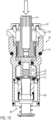
- the spindle 14 must be set to move from the Kv min position to the position shown in the Figures 9 and 10 shown Kv max position (see arrow in Figure 8 ).
- the Kv max position corresponds to the flushing position of the embodiment shown.
- This flushing position is preferably achieved by a Figure 11 shown drive unit 68, which has a uniform drive housing 70 which accommodates an electric motor (not shown), a memory and a control system.
- the drive housing 70 can only accommodate the motor drive.
- the control signals and the memory can be stored in a central control system which is data-coupled to the motor drive which is located inside the drive housing 70.
- An autonomous energy source for example a battery or an accumulator, can be provided in the drive housing 70.
- the storage tank is designed in such a way that the drive unit is given a signal at predetermined time intervals, for example after about 36 hours +/- 10 hours, to set the Kv max position so that the line upstream of the valve is flushed and stale water is drained away.
- the valve according to the invention offers the possibility of releasing volume flows of approximately 1 - 2 m 3 /h during flushing. This value corresponds to Kv max. Due to the special design of the regulating piston 28, a Kv min of approximately 0.05 m 3 /h can be set.
- the control provided in the drive unit 68 can of course also trigger and monitor the flushing based on temperature.
- it has an interface for a temperature sensor that measures and monitors the water temperature in the line area upstream of the valve.
- the motor drive restores the position of the regulating piston 28 previously determined solely by the expansion element.
- the drive unit or manually can be used to Figure 10 shown closed position can be achieved.
- the valve disk 20 is pressed downwards by the drive of the spindle until the sealing disk 22 rests against a sealing seat 72 provided adjacent to the bore 54.
- the valve can thus be shut off for maintenance work or for the controlled section-by-section flushing of individual strands of a water pipe system for cold water.
- the Figure 10 is based on a motor drive that moves the spindle 14 axially like a tappet.
- the spindle is moved until the sealing disk 22 rests against the sealing seat 72.
- the spindle is rotated. If the previously outlined motor drive is provided, this is removed beforehand.
- the spindle 14 is rotated manually using a hexagon provided on the free end of the spindle 14 until the closed position is reached.
Landscapes
- Engineering & Computer Science (AREA)
- General Engineering & Computer Science (AREA)
- Mechanical Engineering (AREA)
- Health & Medical Sciences (AREA)
- Life Sciences & Earth Sciences (AREA)
- Hydrology & Water Resources (AREA)
- Public Health (AREA)
- Water Supply & Treatment (AREA)
- Lift Valve (AREA)
Description
- Die vorliegende Erfindung betrifft ein Ventil für die Trinkwasserinstallation gemäß den oberbegrifflichen Merkmalen von Anspruch 1. Ein solches Ventil ist aus
DE 10 2011 010 840 A1 bekannt. - Die vorliegende Erfindung betrifft insbesondere ein Ventil für die Regelung einer Kaltwasserzirkulation. So ist in dem Ventilgehäuse ein Strömungsweg für das Trinkwasser gebildet, in dem ein thermisches Dehnstoffelement freiliegt, das unter Vorspannung eines Federelementes gegen einen Regulierkolben angelegt ist. Durch die Dehnung des Dehnstoffelementes wird der Regulierkolben relativ zu einer Bohrung bewegt. Hierdurch erfolgt eine temperaturgesteuerte Regulierung der Strömung durch das Ventil. Diese Durchströmung des Ventils erfolgt mit dem Ziel, bei Trinkwasser mit geringer Temperatur ein Kv min einzustellen, sodass bei hinreichend kaltem Trinkwasser nur eine minimale Zirkulation erfolgt. Andererseits soll bei sich erwärmendem Trinkwasser die Zirkulation durch das Ventil erhöht werden, um das warme Trinkwasser möglichst zügig aus dem dem Ventil zugeordneten Leitungsabschnitt auszuleiten und über eine Zirkulationsleitung, die üblicherweise mit einer Pumpe versehen ist, einer Kühlung zuzuführen, wie dies beispielsweise in
EP 2 487 301 B1 beschrieben ist. Die dort beschriebenen Einbausituationen gelten auch für denkbare Einbausituationen des Ventils nach der vorliegenden Erfindung. - Das aus
DE 10 2011 010 840 A1 vorbekannte Ventil zur Steuerung einer Kaltwasserzirkulation lässt noch Wünsche offen. Denn die dort beschriebene Lösung entspricht einem üblichen Ventil für die Regulierung einer Warmwasserzirkulation, die seit langem bekannt ist, lediglich mit dem Unterschied, dass das Verhalten des Dehnstoffelementes so genutzt wird, dass mit steigender Wassertemperatur der Strömungsdurchlass vergrößert und nicht wie bei thermischen Regulierventilen für die Warmwasserzirkulation verkleinert wird. Ansonsten werden aber die Konstruktionsprinzipien von Warmwasser-Regulierventilen identisch übernommen. Diese werden aber den Anforderungen einer Zirkulation in einem Kaltwassersystem nur unzureichend gerecht. - Der vorliegenden Erfindung liegt das Problem zugrunde, ein insofern verbessertes Ventil für die Trinkwasserinstallation anzugeben, das in Abhängigkeit von einer einstellbaren oder fest eingestellten Temperatur bei einer gegenüber dieser Temperatur erhöhten Wassertemperatur einen größeren Volumenstrom des Kaltwassers erlaubt und bei niedriger Temperatur den Durchfluss bevorzugt auf einen minimalen Volumenstrom einregelt.
- Zur Lösung dieses Problems wird mit der vorliegenden Erfindung ein Ventil mit den Merkmalen von Anspruch 1 vorgeschlagen. Eine alternative Lösung ist in Anspruch 5 angegeben. Beide Aspekte in Kombination ergeben ein für die Kaltwasserzirkulation bestmöglich angepasst ausgebildetes Ventil.
- Nach der in Anspruch 1 definierten Lösung kann das Ventil einen sehr geringen Volumenstrom bei Kv Min von etwa 0,05 m3/h +/- 0,01 m3/h einstellen. In Abkehr von üblichen Regulierventilen wird dabei der Regulierspalt nicht in Umfangsrichtung als Ringspalt ausgebildet. Vielmehr ist zwischen der Außenumfangsfläche des Regulierkolbens und der üblicherweise gehäusefest vorgesehenen Bohrung ein sich radial erstreckender Spalt, der umfänglich nicht durchgehend ausgebildet. Durch diesen Spalt wird ein Kv min Strömungsdurchlass ausgebildet. Der Strömungsdurchlass wird ausgebildet, wenn der Regulierkolben mit seinem Kv min-Einstellungsbereich auf Höhe der Bohrung befindlich ist. Diese Lage des Kv min-Einstellungsbereiches wird als Kv min-Stellung bezeichnet.
- Ein sehr geringer Kv min Strömungsdurchlass wird durch einen einzigen sich radial erstreckenden Spalt gebildet. Selbstverständlich können auch mehrere sich radial erstreckende Spalte vorgesehen sein, die jeweils in Umfangsrichtung nicht durchgehend ausgebildet sind. Der Spalt erstreckt sich dabei üblicherweise um wenige Grad in Umfangsrichtung, beispielsweise um zwischen 2 und 8°.
- Der Kv min-Einstellungsbereich des Regulierkolbens ist dabei durch einen gewissen sich in axialer Richtung erstreckenden Bereich des Kolbens ausgebildet, der in der Kv min-Stellung innerhalb der Bohrung liegt.
- Benachbart zu dem Kv min-Einstellungsbereich bildet der Regulierkolben üblicherweise eine Außenumfangsfläche aus, die mit zunehmender Erwärmung des Trinkwassers und damit Dehnung des Dehnstoffelementes zunehmend Kaltwasser durch den Regulierspalt hindurchlässt. So wird der Strömungsdurchlass zwischen dem Regulierkolben und der Bohrung vergrößert, um warmes, abgestandenes Wasser abzufördern.
- Der Regulierkolben hat in seinem Kv min-Einstellungsbereich üblicherweise ein Kunststoff-Dichtelement, dessen Außenumfangsfläche in der Kv min-Stellung des Regulierkolbens den Spalt definiert. Dieses Kunststoff-Dichtelement kann mit seiner Außenumfangsfläche zumindest teilumfänglich an einer die Bohrung vorgebenden, üblicherweise gehäusefest vorgesehenen Gegenfläche anliegen und den Regulierspalt zumindest überwiegend umfänglich abdichten. Als zumindest überwiegend umfängliche Abdichtung wird eine Abdichtung von zumindest 330°, bevorzugt zumindest 350° der umfänglichen Erstreckung der Bohrung angesehen. Gemäß einer bevorzugten Weiterbildung der vorliegenden Erfindung hat der Regulierkolben in seinem Kv min-Einstellungsbereich ein Kunststoff-Dichtelement, das einen in der Kv min-Stellung des Regulierkolbens den Regulierspalt ausbildenden Radialschlitz hat. Dieses Kunststoff-Dichtelement kann mit radialer Vorspannung an der Gegenfläche anliegen. Eine das Dichtelement abstützende Stützfläche, die durch eine Regulierkolbenbasis gebildet sein kann und/oder die Innenumfangsfläche der Bohrung können konisch ausgebildet sein, sodass mit zunehmender Annäherung an die Kv min-Stellung das ringförmige Kunststoff-Dichtelement im Schlitzbereich komprimiert und damit der Strömungsdurchlass verengt wird. Es sollte keine durch das Dehnstoffelement stellbare Position möglich sein, bei welcher der Strömungsdurchlass vollständig verlegt bzw. unmöglich gemacht worden ist.
- Nach der erfindungsgemäßen Ausgestaltung, die in Verbindung mit der Ausformung des zuvor diskutierten Kv min-Einstellungsbereiches an dem Regulierkolben wirkt, hat dieser zusätzlich einen Kv max-Einstellungsbereich. In diesem Kv max-Einstellungsbereich des Regulierkolbens sind an der Außenumfangsfläche des Regulierkolbens Stützstellen ausgebildet. Zwischen diesen Stützstellen liegen Strömungsdurchgangsmulden. Dementsprechend wechseln sich Stützstellen und Strömungsdurchgangsmulden in Umfangsrichtung auf Höhe des Kv max-Einstellungsbereiches ab. In einer Kv max-Stellung des Regulierkolbens reichen die Stützstellen bis zu der Bohrung. Dadurch ergibt sich eine Führung und Abstützung des Kolbens in der Kv max-Stellung. In diesem Zusammenhang ist zu beachten, dass das Federelement zur Verspannung des Regulierkolbens in Richtung auf die Spindel unter Zwischenlage des Dehnstoffelementes in der Kv max-Stellung üblicherweise erheblich komprimiert ist und der Regulierkolben unmittelbar oder mittelbar über das Dehnstoffelement nur unzureichend gegenüber der Spindel axial geführt und lediglich dagegen unmittelbar oder mittelbar stirnseitig abgestützt ist. So bewirken die Stützstellen eine gewisse Führung des Regulierkolbens in der Kv max-Stellung. Dabei müssen die Stützstellen nicht nach Art einer Passung ausgebildet sein. Die Stützstellen können eine Hüllfläche definieren, die geringfügig kleiner als die Innenumfangsfläche der Bohrung ist. Allerdings liegen üblicherweise zumindest zwei Stützstellen an der durch die Bohrung vorgegebenden Gegenfläche an, sodass der Regulierkolben in der Kv max-Stellung durch das die Bohrung üblicherweise definierende Gehäuse gestützt und geführt ist.
- Gemäß einer bevorzugten Weiterbildung der vorliegenden Erfindung befindet sich der Kv max-Einstellungsbereich an dem Regulierkolben zwischen dem Kv min-Einstellungsbereich und der Spindel. Ausgehend von der Spindel bildet der Regulierkolben dementsprechend zunächst den Kv max-Einstellungsbereich, im Anschluss daran einen Reguliereinstellungsbereich zum Regulieren des Strömungsdurchlasses aufgrund der Dehnung des Dehnstoffelementes und einen Kv min-Einstellungsbereich zur Einstellung des Kv min-Strömungsdurchlasses aus. Dieser Einstellungsbereich gibt üblicherweise auch die höchste Position des Regulierkolbens im Rahmen seiner Bewegung innerhalb des Ventilgehäuses an. In dieser höchsten Position liegt der Regulierkolben maximal nahe an einem Kopf des Ventils, der von der Spindel durchragt ist. Der bodenseitige Abstand ist in der höchsten Position dementsprechend am größten.
- Gemäß einer bevorzugten Weiterbildung der vorliegenden Erfindung ist die Spindel in einem Ventileinsatzgehäuse drehbar gelagert. Dieses Ventileinsatzgehäuse bildet zumindest einen zu dem Dehnstoffelement führenden ersten radialen Strömungsdurchlass aus. Dieser erste radiale Strömungsdurchlass kann Einlassöffnung oder Auslassöffnung zu einem Strömungsweg innerhalb des Ventileinsatzgehäuses sein, in dem das Dehnstoffelement freiliegt. An dem der Spindel gegenüberliegenden Ende ist das Ventileinsatzgehäuse gemäß der bevorzugten Weiterbildung der vorliegenden Erfindung mit einer Einlasshülse verbunden, die üblicherweise dichtend mit dem Ventileinsatzgehäuse verbunden, regelmäßig verschraubt ist, und einen zweiten radialen Strömungsdurchlass ausformt, der durch die andere von Einlass- und Auslassöffnung zu dem Strömungsweg gebildet ist. Bevorzugt bildet die Einlasshülse dabei den Einlass der Strömung zu dem Dehnstoffelement aus. Die Einlasshülse bildet ferner einen Boden aus, an dem sich das Federelement mit seinem freien unteren Ende abstützt.
- Diese Ausgestaltung bietet gegenüber der aus
DE 10 2011 010 840 A1 bekannten Lösung den Vorteil, dass die Strömung radial einfließt und nicht - wie bei dem zuvor erwähnten Stand der Technik - durch das Federelement eintritt und erst die Federgänge radial passieren muss, um zu dem Dehnstoffelement zu gelangen. Es sind Fallgestaltungen denkbar, bei denen die Federwindungen relativ eng aufeinanderliegen. In diesem Fall kann die Strömung nicht ungehindert durch das Ventileinsatzgehäuse fließen. - Gemäß einer bevorzugten Weiterbildung der vorliegenden Erfindung bildet die Einlasshülse vorzugsweise einen Stützkragen aus, an dem sich das Federelement innen abstützt. Bei der Feder handelt es sich um eine Schraubenfeder. Der Stützkragen verhindert ein Knicken des Federelements und führt außenseitig die Schraubenfeder. Der Stützkragen wird dabei bevorzugt durch eine Federstützhülse ausgebildet, die axial beweglich relativ zu dem Ventileinsatzgehäuse gehalten ist, bevorzugt innerhalb der Einlasshülse axial in Grenzen beweglich gehalten ist. Dabei bildet die Einlasshülse zumindest einen endseitigen Anschlag aus, an den die Federstützhülse vor der Montage aufgrund der Vorspannung des Federelementes anliegt, sodass das Ventileinsatzgehäuse zusammen mit der Einlasshülse und der Federstützhülse als Einheit gehandhabt und in das Ventilgehäuse eingeschraubt werden können.
- Vorzugsweise stützt sich die Federstützhülse in der Einbausituation an dem Ventilgehäuse ab. Dadurch werden Toträume und dergleichen vermieden, die zwischen dem unterseitig geschlossenen Boden der Einlasshülse und der gegenüberliegenden und das Ventilgehäuse bildenden Wandung entstehen könnten.
- Nach einer weiteren bevorzugten Ausgestaltung ist ein Ventilteller vorgesehen, der eine Dichtscheibe trägt, die in einer Verschlussstellung des Ventils an einem benachbart zu der Bohrung vorgesehenen Dichtsitz anliegt. Der Ventilteller stützt dabei bevorzugt das Dehnstoffelement ab. Der Ventilteller befindet sich dementsprechend zwischen der Spindel und dem Dehnstoffelement und wird üblicherweise bevorzugt unmittelbar von dem spindelseitigen Ende des Dehnstoffelementes kontaktiert.
- Gemäß einer bevorzugten Ausgestaltung der vorliegenden Erfindung ist ein in Wirkverbindung mit der Spindel stehender motorischer Antrieb vorgesehen. Dieser motorische Antrieb eignet sich insbesondere zum Einstellen von Kv max. Kv max des erfindungsgemäßen Ventils erlaubt insbesondere ein Spülen der dem Ventil zugeordneten Leitungsabschnitte. Kv max wird dabei so eingestellt, dass bei den üblichen Systemdrücken ein Volumenstrom von 1,8 m3/h +/- 0,5 m3/h eingestellt werden kann. Eine solche Regelungscharakteristik lässt sich nicht allein durch die Dehnung des Dehnstoffelementes einstellen. Vielmehr wird Kv max bei dem erfindungsgemäßen Ventil bevorzugt durch den motorischen Antrieb eingestellt. Dieser hat hierzu eine Steuerung, die einen Speicher enthält, in den zumindest ein vorbestimmtes Spülregime hinterlegt ist. Die Steuerung ist dabei so eingerichtet, dass der motorische Antrieb den Regulierkolben von einer voreingestellten Regulierstellung in die Kv max-Stellung zum Spülen stellt, bevorzugt nach Art eines Stößels axial vorschiebt. Die voreingestellte Regulierstellung ist dabei eine Stellung des Regulierkolbens, bei welchem der Reguliereinstellungsbereich oder der Kv min-Einstellungsbereich innerhalb der Bohrung liegt. Die Steuerung ist ferner so eingestellt, dass nach Beendigung des Spülens der Regulierkolben durch Antrieb des motorischen Antriebs in die voreingestellte Regulierstellung zurückgestellt wird. Dabei wirkt der motorische Antrieb üblicherweise mit der Spindel zusammen, die zwar auch noch unabhängig von dem Motor und händisch gedreht und damit verstellt werden kann.
- Im Hinblick auf eine kompakte und für sich funktionsfähige Lösung ist der motorische Antrieb, die Steuerung und der Speicher bevorzugt in einem einheitlichen, bevorzugt mit dem Ventilgehäuse verdrehfest verbundenen Antriebsgehäuse aufgenommen. Die Verbindung zwischen dem Ventilgehäuse und einem solchen Antrieb kann beispielsweise gemäß der auf die hiesige Anmelderin zurückgehenden
DE 20 2006 013 186 U1 erfolgen. - Bei dem erfindungsgemäßen Ventil ist der Regulierkörper in dem Kv min-Einstellungsbereich unter Beibehaltung eines konstanten Volumenstromes in Grenzen in der gehäuseseitigen Bohrung axial beweglich. Der Kv min Strömungsdurchlass hat dementsprechend über eine gewisse axiale Erstreckung einen konstanten Strömungsquerschnitt. Entsprechendes gilt für den Kv max-Einstellungsbereich und den Kv max Strömungsdurchlass.
- Die vorliegende Erfindung wird nachstehend anhand eines Ausführungsbeispiels in Verbindung mit der Zeichnung erläutert. In dieser zeigen:
- Figur 1
- eine Längsschnittansicht eines Ausführungsbeispiels eines erfindungsgemäßen Ventils;
- Figur 2
- ein vergrößertes Detail der Schnittansicht gemäß
Figur 1 ; - Figur 3
- eine perspektivische Seitenansicht des Ventileinsatzes gemäß
Figur 1 ; - Figur 4
- eine Längsschnittansicht eines alternativen Ventileinsatzes;
- Figur 5
- ein vergrößertes Detail des Ausführungsbeispiels nach
Figur 1 ; - Figur 6
- eine Querschnittsansicht entlang der Linie VI-VI für eine erste Variante zur Ausgestaltung des Kv min-Einstellungsbereiches;
- Figur 7
- eine gegenüber
Figur 6 abgewandelte zweite Variante; - Figur 8
- das zweite Ausführungsbeispiel in einer Spülstellung;
- Figur 9
- eine Querschnittsansicht entlang der Schnittlinie IX-IX gemäß
Figur 8 - Figur 10
- eine Längsschnittansicht des zweiten Ausführungsbeispiels in einer Geschlossenstellung und
- Figur 11
- das in
Figur 1 gezeigte Ausführungsbeispiel in einer perspektivischen Seitenansicht mit einer Antriebseinheit. - Die
Figur 1 zeigt ein Ausführungsbeispiel eines Ventils mit einem Ventilgehäuse 2, welches eine Einlassöffnung 4 und eine Auslassöffnung 6 ausbildet. In dem Ventilgehäuse 2 ist eine Trennwand 8 vorgesehen, die eine Bohrung definiert, in die ein Ventileinsatz 10 dichtend eingesetzt ist. - Der Ventileinsatz 10 hat ein Ventileinsatzgehäuse 12, in dem eine Spindel 14 drehbar gelagert ist, die über ein Regulieroberteil 16, welches mit dem Ventileinsatzgehäuse 12 verschraubt ist, gelagert ist. Das Regulieroberteil 16 hat Vorsprünge, die einen Teil der Spindel 14 übergreifen und dementsprechend die Spindel 14 axial gegenüber dem Ventiloberteil 16 festlegen. Das Ventiloberteil 16 ist innerhalb des Ventileinsatzgehäuses 12 verschraubt und kann dort verstellt werden, wodurch eine Voreinstellung der Spindel 14 möglich ist.
- Die Spindel 14 ist eine nichtsteigende Spindel, die mit einem Stellelement 18 im Eingriff ist, welches auf der gegenüberliegenden Seite mit einem Ventilteller 20 zusammenwirkt, der mit einem Nocken in eine Ausnehmung des Stellelementes 18 eingreift. An der dem Stellelement 18 gegenüberliegenden Unterseite trägt der Ventilteller 20 eine Dichtscheibe 22, die ein Dehnstoffelement 24 umfänglich umgibt. Das Dehnstoffelement 24 hat einen zentrischen Zapfen, der in eine korrespondierend hierzu ausgebildete, leicht konisch auslaufende Einsatzbohrung des Ventiltellers 20 eingreift. Das Dehnstoffelement 24 hat einen Anlagekragen 26, an den ein Regulierkolben 28 anliegt. Dieser Regulierkolben 28 besteht aus einer metallischen Regulierkolbenbasis 30 und einem aus Kunststoff gebildeten Kunststoff-Dichtelement 32, vgl.
Figur 4 . An der dem Regulierkolben 28 gegenüberliegenden Seite liegt ein Federelement 34 unter Vorspannung gegen das Dehnstoffelement 24 an. Das andere Ende des Federelementes 34 stützt sich an einer Anlagefläche 36 einer mit Bezugszeichen 38 gekennzeichneten Einlasshülse ab. Diese Einlasshülse 38 definiert einander gegenüberliegende Ventileinsatz-Einlassöffnungen 40, durch die das zu regulierende Kaltwasser zu dem Dehnstoffelement 24 gelangt. Mit Bezugszeichen 42 sind Ventileinsatz-Auslassöffnungen gekennzeichnet, durch die die Strömung aus dem Ventileinsatz 10 herausströmt. - Wie insbesondere
Figur 4 erkennen lässt, ist die Einlasshülse 38 mit dem Ventileinsatzgehäuse 12 dort verschraubt. Eine Dichtung dichtet die Schraubverbindung ab. An seinem unteren Ende weist die Einlasshülse 38 einen weiteren Dichtring auf, der den Ventileinsatz 10 gegenüber der in der Trennwand 8 ausgesparten Bohrung abdichtet. Bei dem Ausführungsbeispiel nachFigur 1 ist die Einlasshülse 38 an dem Ventileinsatzgehäuse 12 als Segment eines einheitlichen Bauteils angeformt. - Bei den Ausführungsbeispielen nach den
Figuren 1 bis 3 stützt sich das Federelement 34 unterseitig an einer Federstützhülse 44 ab, die zur Vermeidung von Toträumen an ihrem Außenumfang mit zumindest zwei einander gegenüberliegenden Bohrungen versehen ist. Diese Bohrungen befinden sich im Bereich eines Stützkragens 46, der das als Schraubenfeder ausgebildete Federelement 34 umfänglich stützt. Der Stützkragen 46 überragt einen Stützring 48, gegen den das Federelement 34 endseitig anliegt und der einen radial nach außen vorspringenden Verriegelungsvorsprung ausformt, der axial beweglich ist und in seiner Bewegung nach unten durch einen Anschlag begrenzt ist. So kann die Federstützhülse 44 in Grenzen axial relativ zu dem Ventileinsatz 10 bewegt werden. - Wie ersichtlich wird diese Beweglichkeit dazu genutzt, in der Einbausituation des Ventileinsatzes 10 die Federstützhülse 44 an dem Ventilgehäuse 2 abzustützen und daran anzulegen. So kann die Federstützhülse 44 unterseitig offen oder - wie
Figur 2 verdeutlicht - unterseitig geschlossen ausgebildet sein. - Der Stützkragen 46 hat einen Innendurchmesser, der zur Aufnahme des freien Endes des Dehnelementes 24 angepasst ausgebildet ist.
- An dem gegenüberliegenden Ende des Ventileinsatzes 10 ist ein verdrehfest mit dem Stellelement 18 vorgesehenes Einstellrad 50 vorgesehen, das mit einer Skalierung 52 zusammenwirkt, um einen Kv min-Wert voreinzustellen und den voreingestellten Wert über die Skalierung 52 anzuzeigen, die gegenüber der mit einer entsprechenden Markierung versehenen Spindel bei der Voreinstellung verdreht wird. Das Einstellrad 50 kann aber auch als Motoradapter für eine die Spindel 14 stellende Antriebseinheit genutzt werden.
- Die
Figur 4 zeigt ein gegenüber dem Ausführungsbeispiel nach denFiguren 1 bis 3 leicht abgewandeltes Ausführungsbeispiel. Dieses unterscheidet sich im Wesentlichen lediglich durch die Gestaltung eines die Anlagefläche für das Federelement bildenden Bodens 36, der hier flach ausgebildet ist und nicht mit dem Ventilgehäuse 2 in der Einbausituation zusammenwirkt. Gleiche Bauteile sind gegenüber dem zuvor diskutierten Ausführungsbeispiel mit gleichen Bezugszeichen gekennzeichnet. - Die
Figur 5 zeigt den Regulierkolben 28 in seiner Kv min-Stellung und gilt auch für das erste Ausführungsbeispiel. In dieser Stellung wirkt die Außenumfangsfläche des Kunststoff-Dichtelementes 32 als nahezu vollständige umfängliche Abdichtung in einer durch das Ventileinsatzgehäuse 12 definierten Bohrung 54. -
Figur 6 zeigt dabei mit Bezugszeichen 56 gekennzeichnete Strömungsdurchlässe für eine erste Variante, die durch radiale Kerben 58 innerhalb der Bohrung 54 gebildet sind. Die Kerben 58 erstrecken sich in radialer Richtung, haben allerdings lediglich eine geringe Umfangserstreckung. Es sind drei Kerben 58 auf dem Umfang verteilt vorgesehen, die in der Summe den Strömungsdurchlass in der gezeigten Kv min-Stellung des Regulierkolbens 28 einstellen. Das Kunststoff-Dichtelement 32 ist bei dieser Variante umfänglich geschlossen. - Anders verhält es sich bei dem Ausführungsbeispiel nach
Figur 7 . Dort ist das inFigur 6 nach Art eines geschlossenen Dichtringes ausgebildete Kunststoff-Dichtelement 32 geschlitzt. So ergibt sich eine C-förmige Gestaltung mit einem Radialschlitz 60, der den einzigen Strömungsdurchlass 56 ausbildet. Es ist ohne Weiteres vorstellbar, dass bei einer konischen Ausgestaltung der Regulierkolbenbasis 30 und/oder der Bohrung 54 dieser Schlitz abhängig von der Stellung des Dehnstoffelementes 24 vergrößert bzw. verkleinert werden kann, um den Strömungsdurchlass 56 variabel einzustellen. - Die
Figuren 5 ,6 und 7 zeigen die Konstellation von Regulierkolben 28 und Bohrung 54 in der Kv min-Stellung. Wie zuvor beschrieben ist der Strömungsdurchlass 56 nicht umfänglich zwischen der Bohrung 54 und dem Regulierkolben 28 ausgebildet. Vielmehr ist lediglich zumindest ein in Umfangsrichtung diskreter Abschnitt vorgesehen, der eine Strömung durchlässt. Ansonsten liegt das Kunststoff-Dichtelement 32 im Wesentlichen vollumfänglich an der Innenumfangsfläche der überwiegend kreisförmigen Bohrung 54 an. Der durch den Regulierkolben 28 in der zuvor beschriebenen Stellung gebildete Kv min-Einstellungsbereich ist inFigur 5 mit I gekennzeichnet. - In Richtung auf die Spindel 14 vorgelagert bildet der Regulierkolben 28 einen Kv max-Einstellungsbereich aus, der mit Bezugszeichen III gekennzeichnet ist. Wie die Schnittansicht gemäß
Figur 9 verdeutlicht, hat der Regulierkolben 28 eine im Wesentlichen sternförmige Querschnittsform und bildet auf dem Umfang verteilt vorgesehene Stützstellen 62 aus, zwischen denen Strömungsdurchgangsmulden 64 ausgeformt sind. Die Stützstellen 62 reichen bis zu der Innenumfangsfläche der Bohrung 54 und können sich an diesen auch zur Widerlagerung einer ggf. auftretenden Knicklast des Federelementes 34 abstützen. Die Strömungsdurchgangsmulden 54 bilden in der gezeigten Kv max-Stellung den Kv max-Strömungsdurchlass aus, der mit Bezugszeichen 66 gekennzeichnet ist. Diese Ausgestaltung ist auch bei dem Ausführungsbeispiel nachFigur 1 verwirklicht. - Zwischen dem mit Bezugszeichen III gekennzeichneten Kv max-Einstellungsbereich des Regulierkolbens 28 gemäß den
Figuren 8 und9 und dem Kv min-Einstellungsbereich I gemäß denFiguren 6 bis 8 befindet sich ein Reguliereinstellungsbereich II, in welchem der Strömungsdurchlass vergrößert wird. Dieser Reguliereinstellungsbereich II überstreicht die Innenumfangsfläche der Bohrung 54 aufgrund der Dehnung des Dehnstoffelementes 24. - Wie ersichtlich muss die Spindel 14 gestellt werden, um ausgehend von der Kv min-Stellung zu der in den
Figuren 9 und10 gezeigten Kv max-Stellung zu gelangen (vgl. Pfeil inFigur 8 ). Die Kv max-Stellung entspricht dabei der Spülstellung des gezeigten Ausführungsbeispiels. Diese Spülstellung wird bevorzugt durch eine inFigur 11 gezeigten Antriebseinheit 68 eingestellt, die ein einheitliches Antriebsgehäuse 70 aufweist, welches einen nicht gezeigten elektrischen Motor, einen Speicher und eine Steuerung in sich aufnimmt. Bei einer Abwandlung kann das Antriebsgehäuse 70 lediglich den motorischen Antrieb in sich aufnehmen. Die Steuersignale und der Speicher können in einer zentralen Steuerung hinterlegt sein, die datenmäßig mit dem motorischen Antrieb, der sich innerhalb des Antriebsgehäuses 70 befindet, gekoppelt ist. In dem Antriebsgehäuse 70 kann eine autonome Energiequelle, beispielsweise eine Batterie oder ein Akkumulator vorgesehen sein. - Der Speicher ist dabei so ausgebildet, dass der Antriebseinheit in vorbestimmten Zeitintervallen, beispielsweise nach etwa 36 Stunden +/- 10 Stunden ein Signal gegeben wird, die Kv max-Stellung einzustellen, sodass die dem Ventil vorgelagerte Leitung gespült und abgestandenes Wasser abgefördert wird.
- Das erfindungsgemäße Ventil bietet dabei die Möglichkeit, Volumenströme von etwa 1 - 2 m3/h beim Spülen abzulassen. Dieser Wert entspricht Kv max. Durch die besondere Ausgestaltung des Regulierkolbens 28 kann ein Kv min von etwa 0,05 m3/h eingestellt werden.
- Die in der Antriebseinheit 68 vorgesehene Steuerung kann selbstverständlich auch temperaturgesteuert das Spülen auslösen und überwachen. Sie hat hierzu eine Schnittstelle für einen Temperatursensor, der die Wassertemperatur in dem dem Ventil vorgelagerten Leitungsbereich misst und überwacht.
- Nach Beendigung des Spülens stellt der motorische Antrieb die zuvor allein durch das Dehnstoffelement gegebene Stellung des Regulierkolbens 28 wieder ein.
- Über die Antriebseinheit oder händisch kann die in
Figur 10 gezeigte Verschlussstellung erreicht werden. Hierbei wird durch den Antrieb der Spindel der Ventilteller 20 so weit nach unten gedrückt, bis die Dichtscheibe 22 an einem benachbart zu der Bohrung 54 vorgesehenen Dichtsitz 72 anliegt. Somit kann das Ventil zu Wartungsarbeiten oder zum kontrollierten abschnittsweisen Spülen einzelner Stränge eines Wasserleitungssystems für Kaltwasser abgesperrt werden. - Die
Figur 10 geht dabei von einem motorischen Antrieb aus, der die Spindel 14 axial nach Art eines Stößels bewegt. Die Bewegung der Spindel erfolgt bis die Dichtscheibe 22 gegen den Dichtsitz 72 anliegt. Beim händischen Schließen des Ventils wird die Spindel gedreht. Sofern der vorher skizzierte motorische Antrieb vorgesehen ist, wird dieser zuvor entfernt. Die Spindel 14 wird über einen an dem freien Ende der Spindel 14 vorgesehenen Sechskant händisch gedreht, bis die Verschlussstellung erreicht ist. -
- 2
- Ventilgehäuse
- 4
- Einlassöffnung
- 6
- Auslassöffnung
- 8
- Trennwand
- 10
- Ventileinsatz
- 12
- Ventileinsatzgehäuse
- 14
- Spindel
- 16
- Regulieroberteil
- 18
- Stellelement
- 20
- Ventilteller
- 22
- Dichtscheibe
- 24
- Dehnstoffelement
- 26
- Anlagekragen
- 28
- Regulierkolben
- 30
- Regulierkolbenbasis
- 32
- Kunststoff-Dichtelement
- 34
- Federelement
- 36
- Boden/Anlagefläche
- 38
- Einlasshülse
- 40
- Ventileinsatz-Einlassöffnung
- 42
- Ventileinsatz-Auslassöffnung
- 44
- Federstützhülse
- 46
- Stützkragen
- 48
- Stützring
- 50
- Einstellrad
- 52
- Skalierung
- 54
- Bohrung
- 56
- Strömungsdurchlass Kv min
- 58
- Kerbe
- 60
- Radialschlitz
- 62
- Stützstelle
- 64
- Strömungsdurchgangsmulde
- 66
- Strömungsdurchlass Kv max
- 68
- Antriebseinheit
- 70
- Antriebsgehäuse
- 72
- Dichtsitz
- I
- Kv min-Einstellbereich
- II
- Reguliereinstellungsbereich
- III
- Kv max-Einstellungsbereich
Claims (11)
- Ventil für die Trinkwasserinstallation mit einem Ventilgehäuse (2) mit Anschlüssen zu einer Rohrleitung und mit einem in dem Ventilgehäuse (2) beweglichen Regulierkolben (28), der mit einer an der Außenseite des Ventilgehäuses (2) freiliegenden Spindel (14) gekoppelt ist und auf der der Spindel (14) gegenüberliegenden Seite mit einem in einem Strömungsweg durch das Ventilgehäuse (2) freiliegendem thermischen Dehnstoffelement (24) zusammenwirkt, das unter Vorspannung eines Federelementes (34) gegen den Regulierkolben (28) angelegt ist und durch dessen Dehnung der Regulierkolben (28) relativ zu einer Bohrung (54) beweglich ist, wobei der Regulierkolben (28) einen Kv min-Einstellungsbereich (I) ausbildet, durch den in einer Kv min-Stellung des Regulierkolbens (28) zwischen dem Regulierkolben (28) und der Bohrung (54) durch zumindest einen an dem Regulierkolben (28) und/oder der Bohrung (54) sich radial erstreckenden Spalt (58, 60) ein Kv min-Strömungsdurchlass (56) ausgebildet ist, dadurch gekennzeichnet,dass der in der Kv min-Stellung ausgebildete Spalt (58, 60) umfänglich nicht durchgehend ist und dass der Kv min-Strömungsdurchlass (56) einen über eine gewisse axiale Erstreckung konstanten Strömungsquerschnitt hat, wobei eine axiale Richtung einer Bewegungsrichtung des Regulierkolbens (28) entspricht,dass der Regulierkolben (28) einen Kv max-Einstellungsbereich (III) mit an der Außenumfangsfläche des Regulierkolbens ausgebildeten Stützstellen (62) und dazwischenliegende Strömungsdurchgangsmulden (64) ausbildet unddass in der Kv max-Stellung des Regulierkolbens (28) die Stützstellen (62) bis zu der Bohrung (54) reichen und die dazwischen vorgesehenen Strömungsdurchgangsmulden (64) einen Kv max-Strömungsdurchlass (III) ausbilden.
- Ventil nach Anspruch 1, dadurch gekennzeichnet, dass der Regulierkolben (28) in seinem Kv min-Einstellungsbereich (I) ein Kunststoff-Dichtelement (32) aufweist, dessen Außenumfangsfläche in der Kv min-Stellung des Regulierkolbens (28) den Spalt (58, 60) definiert.
- Ventil nach Anspruch 1 oder 2, dadurch gekennzeichnet, dass der Regulierkolben (28) in seinem Kv min-Einstellungsbereich (I) ein Kunststoff-Dichtelement (32) aufweist, dessen Außenumfangsfläche in der Kv min-Stellung des Regulierkolbens (28) zumindest teilumfänglich an einer die Bohrung (54) vorgebenden Gegenfläche anliegt.
- Ventil nach einem der Ansprüche 1 bis 3, dadurch gekennzeichnet, dass der Regulierkolben (28) in seinem Kv min-Einstellungsbereich (I) ein Kunststoff-Dichtelement (32) aufweist, das einen in der Kv min-Stellung des Regulierkolbens (28) den Spalt ausbildenden Radialschlitz (60) hat.
- Ventil nach Anspruch 1, dadurch gekennzeichnet, dass der Kv max-Einstellungsbereich (III) an dem Regulierkolben (28) zwischen dem Kv min-Einstellungsbereich (I) und der Spindel (14) vorgesehen ist.
- Ventil nach einem der vorherigen Ansprüche, dadurch gekennzeichnet, dass die Spindel (14) in einem Ventileinsatzgehäuse (12) drehbar gelagert ist, das zumindest einen zu dem Dehnstoffelement (24) führenden ersten radialen Strömungsauslass (42) ausbildet und an seinem der Spindel (14) gegenüberliegenden Ende mit einer Einlasshülse (38) verbunden ist, die zumindest einen zweiten radialen Strömungsdurchlass (40) und einen Boden (36) ausbildet, an dem sich das Federelement (34) abstützt.
- Ventil nach Anspruch 6, dadurch gekennzeichnet, dass der Boden (36) durch eine axial beweglich zu dem Ventileinsatzgehäuse (12) gehaltene Federstützhülse (44) gebildet ist, die sich an dem Ventilgehäuse (2) abstützt und für das Federelement (34) einen innen stützenden Stützkragen (46) ausbildet.
- Ventil nach einem der vorherigen Ansprüche, gekennzeichnet durch einen das Dehnstoffelement (24) abstützenden Ventilteller (20), der eine Dichtscheibe (22) trägt, die in einer Verschlussstellung des Ventils an einem benachbart zu der Bohrung (54) vorgesehenen Dichtsitz (72) anliegt.
- Ventil nach einem der vorherigen Ansprüche, gekennzeichnet durch einen mit der Spindel (14) in Wirkverbindung stehenden motorischen Antrieb (68), der mit einer Steuerung verbindbar ist, die einen Speicher enthält, in dem ein vorbestimmtes Spülregime hinterlegt ist, und dass die Steuerung so eingerichtet ist, dass der motorische Antrieb (68) den Regulierkolben (28) von einer voreingestellten Regulierstellung zum Spülen in die Kv max-Stellung stellt und nach Beendigung des Spülens den Regulierkolben (28) in die voreingestellte Regulierstellung zurückstellt.
- Ventil nach Anspruch 9, dadurch gekennzeichnet, dass der motorische Antrieb (68), die Steuerung und der Speicher in einem einheitlichen, mit dem Ventilgehäuse (2) verbundenen Antriebsgehäuse (70) aufgenommen ist.
- Ventil nach Anspruch 10, dadurch gekennzeichnet, dass das Ventilgehäuse (2) mit einem Formschlusselement und das Antriebsgehäuse (70) mit einem Formschlussgegenelement versehen ist, über welche das Antriebsgehäuse (70) verdrehfest mit dem Ventilgehäuse (2) verbindbar ist.
Applications Claiming Priority (1)
| Application Number | Priority Date | Filing Date | Title |
|---|---|---|---|
| DE202019001118.8U DE202019001118U1 (de) | 2019-03-08 | 2019-03-08 | Ventil für die Trinkwasserinstallation |
Publications (2)
| Publication Number | Publication Date |
|---|---|
| EP3705634A1 EP3705634A1 (de) | 2020-09-09 |
| EP3705634B1 true EP3705634B1 (de) | 2024-09-18 |
Family
ID=66817181
Family Applications (1)
| Application Number | Title | Priority Date | Filing Date |
|---|---|---|---|
| EP20160663.9A Active EP3705634B1 (de) | 2019-03-08 | 2020-03-03 | Ventil für die trinkwasserinstallation |
Country Status (7)
| Country | Link |
|---|---|
| US (1) | US11226051B2 (de) |
| EP (1) | EP3705634B1 (de) |
| CN (1) | CN111664261B (de) |
| CA (1) | CA3074475C (de) |
| DE (1) | DE202019001118U1 (de) |
| DK (1) | DK3705634T3 (de) |
| SG (1) | SG10202002091VA (de) |
Family Cites Families (19)
| Publication number | Priority date | Publication date | Assignee | Title |
|---|---|---|---|---|
| DE1750923B2 (de) * | 1968-06-19 | 1972-11-30 | Danfoss A/S, Nordborg (Dänemark) | Drosseleinrichtung zum konstanthalten einer durchflussmenge |
| DE2206975C3 (de) * | 1972-02-14 | 1978-12-07 | Knorr-Bremse Gmbh, 8000 Muenchen | Schutzvorrichtung für Mehrkreisdruckluftleitungssysteme, insbesondere für Mehrkreisbremsanlage!! von Kraftfahrzeugen |
| FR2225670B1 (de) * | 1973-04-10 | 1975-12-26 | Adar Sa | |
| AU667629B2 (en) * | 1993-05-27 | 1996-03-28 | Sumitomo Electric Industries, Ltd. | Changeover valve and flow control valve assembly having the same |
| DE9404344U1 (de) | 1994-02-07 | 1994-06-09 | Gampper Gmbh, 67821 Alsenz | Thermostatventil mit Voreinstellung der Durchflußmenge |
| DE20109619U1 (de) * | 2001-06-08 | 2001-09-27 | Rossweiner Armaturen und Messgeräte GmbH, 04741 Roßwein | Thermostatisch betätigtes Drosselventil für Warmwasser-Zirkulationssysteme |
| EP1385072B1 (de) | 2002-07-18 | 2009-03-25 | Gebr. Kemper GmbH + Co. KG Metallwerke | Regulierventil |
| DE202006013186U1 (de) | 2006-08-28 | 2008-01-17 | Gebr. Kemper Gmbh & Co. Kg Metallwerke | Motorgetriebenes Ventil |
| CH700118B1 (de) * | 2007-01-22 | 2010-06-30 | Fischer Georg Jrg Ag | Regelventil und damit aufgebaute Zirkulationsregelung für einen Warmwasserkreislauf. |
| CN201651332U (zh) * | 2009-10-14 | 2010-11-24 | 天佰立(北京)新技术发展有限公司 | 可调kv值的防冻锁闭阀 |
| CN102062257B (zh) * | 2009-11-11 | 2013-01-23 | 天佰立(北京)新技术发展有限公司 | 一种可调 kv 值的防漏恒温阀 |
| FR2958002B1 (fr) | 2010-03-23 | 2015-01-02 | Vernet | Vanne thermostatique pour un circuit de circulation de fluide et procede de fabrication d'une telle vanne |
| DE102011010840B4 (de) | 2011-02-10 | 2019-08-14 | Oventrop Gmbh & Co. Kg | Trink- oder Brauchwassersystem |
| DE102011079161B4 (de) * | 2011-07-14 | 2016-02-11 | Aba Beul Gmbh | Etagenregulierventil |
| CN102644779B (zh) * | 2012-04-26 | 2014-04-30 | 深圳市禹安节水科技有限公司 | 一种恒流器 |
| CN104930197B (zh) * | 2015-05-19 | 2017-08-29 | 苗蕴博 | 一种流量调节阀 |
| DE202015006366U1 (de) * | 2015-09-07 | 2016-12-08 | Gebr. Kemper Gmbh + Co. Kg Metallwerke | Trink- und Brauchwasserversorgungseinrichtung eines Gebäudes und Regulierventil hierfür |
| DE102016119572B4 (de) * | 2016-10-13 | 2021-07-29 | GEMÜ Gebr. Müller Apparatebau GmbH & Co. KG | Verfahren zum Betreiben einer Antriebseinheit und Antriebseinheit |
| DE102017110343A1 (de) * | 2017-05-12 | 2018-11-15 | Minebea Mitsumi Inc. | Linearstellantrieb, insbesondere Ventil |
-
2019
- 2019-03-08 DE DE202019001118.8U patent/DE202019001118U1/de active Active
-
2020
- 2020-03-03 EP EP20160663.9A patent/EP3705634B1/de active Active
- 2020-03-03 DK DK20160663.9T patent/DK3705634T3/da active
- 2020-03-04 US US16/809,130 patent/US11226051B2/en active Active
- 2020-03-04 CA CA3074475A patent/CA3074475C/en active Active
- 2020-03-06 SG SG10202002091VA patent/SG10202002091VA/en unknown
- 2020-03-09 CN CN202010159164.4A patent/CN111664261B/zh active Active
Also Published As
| Publication number | Publication date |
|---|---|
| CN111664261B (zh) | 2022-05-27 |
| SG10202002091VA (en) | 2020-10-29 |
| CA3074475C (en) | 2023-03-21 |
| DE202019001118U1 (de) | 2019-05-24 |
| DK3705634T3 (da) | 2024-10-07 |
| EP3705634A1 (de) | 2020-09-09 |
| CA3074475A1 (en) | 2020-09-08 |
| US20200284371A1 (en) | 2020-09-10 |
| US11226051B2 (en) | 2022-01-18 |
| CN111664261A (zh) | 2020-09-15 |
Similar Documents
| Publication | Publication Date | Title |
|---|---|---|
| EP2501965B1 (de) | Vorgesteuertes druckbegrenzungsventil | |
| EP2203668B1 (de) | Regulierventil | |
| EP2226697B1 (de) | Durchflussmengenregler | |
| EP1516237B1 (de) | Durchflussmengenregler | |
| EP2677194A2 (de) | Verstellbare Dämpfventileinrichtung | |
| EP3287679B1 (de) | Membranventil | |
| EP0715692B1 (de) | Pumpenschutzventil | |
| DE19602796B4 (de) | Steuerventil für kleinen Durchfluß | |
| EP3139074B1 (de) | Frostsichere aussenarmatur und verfahren zur montage derselben | |
| EP4086491B1 (de) | Ventilanordnung | |
| AT405675B (de) | Vorrichtung zur begrenzung der vorspannung einer regelfeder | |
| EP2183509B1 (de) | Vorrichtung zur drosselung des freien querschnittes einer dampfleitung oder dergleichen | |
| EP4060210B1 (de) | Rückflussverhindererventil | |
| CH638909A5 (de) | Thermoskopische einheit. | |
| DE1810308A1 (de) | Thermostatisch gesteuerter Absperrhahn | |
| EP0520135B1 (de) | Überdruckventileinrichtung für den Kühlkreislauf einer flüssigkeitsgekühlten Brennkraftmaschine | |
| EP3705634A1 (de) | Ventil für die trinkwasserinstallation | |
| EP0737905A2 (de) | Thermostatventil | |
| EP1001196B1 (de) | Druckbegrenzungsventil, insbesondere für Fahrzeuge | |
| EP2496867A1 (de) | Ventilanordnung | |
| EP0681098A1 (de) | Thermostatventil | |
| DE19627306A1 (de) | Sperrventil mit Druckbegrenzung | |
| WO2001020207A1 (de) | Einbauventil für einen gliederheizkörper | |
| DE10132001C2 (de) | Thermostatischer Regler zur Regelung der Durchflussmenge eines Fluids | |
| DE102019218402B4 (de) | Federdom für ein Hydraulikventil und Hydraulikventil mit einem solchen Federdom |
Legal Events
| Date | Code | Title | Description |
|---|---|---|---|
| PUAI | Public reference made under article 153(3) epc to a published international application that has entered the european phase |
Free format text: ORIGINAL CODE: 0009012 |
|
| STAA | Information on the status of an ep patent application or granted ep patent |
Free format text: STATUS: THE APPLICATION HAS BEEN PUBLISHED |
|
| AK | Designated contracting states |
Kind code of ref document: A1 Designated state(s): AL AT BE BG CH CY CZ DE DK EE ES FI FR GB GR HR HU IE IS IT LI LT LU LV MC MK MT NL NO PL PT RO RS SE SI SK SM TR |
|
| AX | Request for extension of the european patent |
Extension state: BA ME |
|
| STAA | Information on the status of an ep patent application or granted ep patent |
Free format text: STATUS: REQUEST FOR EXAMINATION WAS MADE |
|
| 17P | Request for examination filed |
Effective date: 20201117 |
|
| RBV | Designated contracting states (corrected) |
Designated state(s): AL AT BE BG CH CY CZ DE DK EE ES FI FR GB GR HR HU IE IS IT LI LT LU LV MC MK MT NL NO PL PT RO RS SE SI SK SM TR |
|
| REG | Reference to a national code |
Ref country code: HK Ref legal event code: DE Ref document number: 40040399 Country of ref document: HK |
|
| STAA | Information on the status of an ep patent application or granted ep patent |
Free format text: STATUS: EXAMINATION IS IN PROGRESS |
|
| 17Q | First examination report despatched |
Effective date: 20211206 |
|
| P01 | Opt-out of the competence of the unified patent court (upc) registered |
Effective date: 20240304 |
|
| RAP3 | Party data changed (applicant data changed or rights of an application transferred) |
Owner name: GEBR. KEMPER GMBH + CO. KG |
|
| GRAP | Despatch of communication of intention to grant a patent |
Free format text: ORIGINAL CODE: EPIDOSNIGR1 |
|
| STAA | Information on the status of an ep patent application or granted ep patent |
Free format text: STATUS: GRANT OF PATENT IS INTENDED |
|
| INTG | Intention to grant announced |
Effective date: 20240424 |
|
| GRAS | Grant fee paid |
Free format text: ORIGINAL CODE: EPIDOSNIGR3 |
|
| GRAA | (expected) grant |
Free format text: ORIGINAL CODE: 0009210 |
|
| STAA | Information on the status of an ep patent application or granted ep patent |
Free format text: STATUS: THE PATENT HAS BEEN GRANTED |
|
| AK | Designated contracting states |
Kind code of ref document: B1 Designated state(s): AL AT BE BG CH CY CZ DE DK EE ES FI FR GB GR HR HU IE IS IT LI LT LU LV MC MK MT NL NO PL PT RO RS SE SI SK SM TR |
|
| REG | Reference to a national code |
Ref country code: GB Ref legal event code: FG4D Free format text: NOT ENGLISH |
|
| REG | Reference to a national code |
Ref country code: CH Ref legal event code: EP |
|
| REG | Reference to a national code |
Ref country code: NL Ref legal event code: FP Ref country code: DE Ref legal event code: R096 Ref document number: 502020009240 Country of ref document: DE |
|
| REG | Reference to a national code |
Ref country code: DK Ref legal event code: T3 Effective date: 20241001 |
|
| REG | Reference to a national code |
Ref country code: IE Ref legal event code: FG4D Free format text: LANGUAGE OF EP DOCUMENT: GERMAN |
|
| REG | Reference to a national code |
Ref country code: LT Ref legal event code: MG9D |
|
| PG25 | Lapsed in a contracting state [announced via postgrant information from national office to epo] |
Ref country code: NO Free format text: LAPSE BECAUSE OF FAILURE TO SUBMIT A TRANSLATION OF THE DESCRIPTION OR TO PAY THE FEE WITHIN THE PRESCRIBED TIME-LIMIT Effective date: 20241218 |
|
| PG25 | Lapsed in a contracting state [announced via postgrant information from national office to epo] |
Ref country code: GR Free format text: LAPSE BECAUSE OF FAILURE TO SUBMIT A TRANSLATION OF THE DESCRIPTION OR TO PAY THE FEE WITHIN THE PRESCRIBED TIME-LIMIT Effective date: 20241219 Ref country code: FI Free format text: LAPSE BECAUSE OF FAILURE TO SUBMIT A TRANSLATION OF THE DESCRIPTION OR TO PAY THE FEE WITHIN THE PRESCRIBED TIME-LIMIT Effective date: 20240918 |
|
| PG25 | Lapsed in a contracting state [announced via postgrant information from national office to epo] |
Ref country code: BG Free format text: LAPSE BECAUSE OF FAILURE TO SUBMIT A TRANSLATION OF THE DESCRIPTION OR TO PAY THE FEE WITHIN THE PRESCRIBED TIME-LIMIT Effective date: 20240918 |
|
| PG25 | Lapsed in a contracting state [announced via postgrant information from national office to epo] |
Ref country code: LV Free format text: LAPSE BECAUSE OF FAILURE TO SUBMIT A TRANSLATION OF THE DESCRIPTION OR TO PAY THE FEE WITHIN THE PRESCRIBED TIME-LIMIT Effective date: 20240918 |
|
| PG25 | Lapsed in a contracting state [announced via postgrant information from national office to epo] |
Ref country code: HR Free format text: LAPSE BECAUSE OF FAILURE TO SUBMIT A TRANSLATION OF THE DESCRIPTION OR TO PAY THE FEE WITHIN THE PRESCRIBED TIME-LIMIT Effective date: 20240918 |
|
| PG25 | Lapsed in a contracting state [announced via postgrant information from national office to epo] |
Ref country code: RS Free format text: LAPSE BECAUSE OF FAILURE TO SUBMIT A TRANSLATION OF THE DESCRIPTION OR TO PAY THE FEE WITHIN THE PRESCRIBED TIME-LIMIT Effective date: 20241218 |
|
| PG25 | Lapsed in a contracting state [announced via postgrant information from national office to epo] |
Ref country code: RS Free format text: LAPSE BECAUSE OF FAILURE TO SUBMIT A TRANSLATION OF THE DESCRIPTION OR TO PAY THE FEE WITHIN THE PRESCRIBED TIME-LIMIT Effective date: 20241218 Ref country code: NO Free format text: LAPSE BECAUSE OF FAILURE TO SUBMIT A TRANSLATION OF THE DESCRIPTION OR TO PAY THE FEE WITHIN THE PRESCRIBED TIME-LIMIT Effective date: 20241218 Ref country code: LV Free format text: LAPSE BECAUSE OF FAILURE TO SUBMIT A TRANSLATION OF THE DESCRIPTION OR TO PAY THE FEE WITHIN THE PRESCRIBED TIME-LIMIT Effective date: 20240918 Ref country code: HR Free format text: LAPSE BECAUSE OF FAILURE TO SUBMIT A TRANSLATION OF THE DESCRIPTION OR TO PAY THE FEE WITHIN THE PRESCRIBED TIME-LIMIT Effective date: 20240918 Ref country code: GR Free format text: LAPSE BECAUSE OF FAILURE TO SUBMIT A TRANSLATION OF THE DESCRIPTION OR TO PAY THE FEE WITHIN THE PRESCRIBED TIME-LIMIT Effective date: 20241219 Ref country code: FI Free format text: LAPSE BECAUSE OF FAILURE TO SUBMIT A TRANSLATION OF THE DESCRIPTION OR TO PAY THE FEE WITHIN THE PRESCRIBED TIME-LIMIT Effective date: 20240918 Ref country code: BG Free format text: LAPSE BECAUSE OF FAILURE TO SUBMIT A TRANSLATION OF THE DESCRIPTION OR TO PAY THE FEE WITHIN THE PRESCRIBED TIME-LIMIT Effective date: 20240918 |
|
| PG25 | Lapsed in a contracting state [announced via postgrant information from national office to epo] |
Ref country code: IS Free format text: LAPSE BECAUSE OF FAILURE TO SUBMIT A TRANSLATION OF THE DESCRIPTION OR TO PAY THE FEE WITHIN THE PRESCRIBED TIME-LIMIT Effective date: 20250118 Ref country code: PT Free format text: LAPSE BECAUSE OF FAILURE TO SUBMIT A TRANSLATION OF THE DESCRIPTION OR TO PAY THE FEE WITHIN THE PRESCRIBED TIME-LIMIT Effective date: 20250120 |
|
| PG25 | Lapsed in a contracting state [announced via postgrant information from national office to epo] |
Ref country code: RO Free format text: LAPSE BECAUSE OF FAILURE TO SUBMIT A TRANSLATION OF THE DESCRIPTION OR TO PAY THE FEE WITHIN THE PRESCRIBED TIME-LIMIT Effective date: 20240918 Ref country code: SM Free format text: LAPSE BECAUSE OF FAILURE TO SUBMIT A TRANSLATION OF THE DESCRIPTION OR TO PAY THE FEE WITHIN THE PRESCRIBED TIME-LIMIT Effective date: 20240918 |
|
| PG25 | Lapsed in a contracting state [announced via postgrant information from national office to epo] |
Ref country code: ES Free format text: LAPSE BECAUSE OF FAILURE TO SUBMIT A TRANSLATION OF THE DESCRIPTION OR TO PAY THE FEE WITHIN THE PRESCRIBED TIME-LIMIT Effective date: 20240918 |
|
| PG25 | Lapsed in a contracting state [announced via postgrant information from national office to epo] |
Ref country code: EE Free format text: LAPSE BECAUSE OF FAILURE TO SUBMIT A TRANSLATION OF THE DESCRIPTION OR TO PAY THE FEE WITHIN THE PRESCRIBED TIME-LIMIT Effective date: 20240918 |
|
| PG25 | Lapsed in a contracting state [announced via postgrant information from national office to epo] |
Ref country code: PL Free format text: LAPSE BECAUSE OF FAILURE TO SUBMIT A TRANSLATION OF THE DESCRIPTION OR TO PAY THE FEE WITHIN THE PRESCRIBED TIME-LIMIT Effective date: 20240918 Ref country code: CZ Free format text: LAPSE BECAUSE OF FAILURE TO SUBMIT A TRANSLATION OF THE DESCRIPTION OR TO PAY THE FEE WITHIN THE PRESCRIBED TIME-LIMIT Effective date: 20240918 |
|
| PG25 | Lapsed in a contracting state [announced via postgrant information from national office to epo] |
Ref country code: IT Free format text: LAPSE BECAUSE OF FAILURE TO SUBMIT A TRANSLATION OF THE DESCRIPTION OR TO PAY THE FEE WITHIN THE PRESCRIBED TIME-LIMIT Effective date: 20240918 Ref country code: SK Free format text: LAPSE BECAUSE OF FAILURE TO SUBMIT A TRANSLATION OF THE DESCRIPTION OR TO PAY THE FEE WITHIN THE PRESCRIBED TIME-LIMIT Effective date: 20240918 |
|
| REG | Reference to a national code |
Ref country code: DE Ref legal event code: R097 Ref document number: 502020009240 Country of ref document: DE |
|
| PGFP | Annual fee paid to national office [announced via postgrant information from national office to epo] |
Ref country code: CH Payment date: 20250401 Year of fee payment: 6 |
|
| PLBE | No opposition filed within time limit |
Free format text: ORIGINAL CODE: 0009261 |
|
| STAA | Information on the status of an ep patent application or granted ep patent |
Free format text: STATUS: NO OPPOSITION FILED WITHIN TIME LIMIT |
|
| 26N | No opposition filed |
Effective date: 20250619 |
|
| PG25 | Lapsed in a contracting state [announced via postgrant information from national office to epo] |
Ref country code: SE Free format text: LAPSE BECAUSE OF FAILURE TO SUBMIT A TRANSLATION OF THE DESCRIPTION OR TO PAY THE FEE WITHIN THE PRESCRIBED TIME-LIMIT Effective date: 20240918 |
|
| PG25 | Lapsed in a contracting state [announced via postgrant information from national office to epo] |
Ref country code: MC Free format text: LAPSE BECAUSE OF FAILURE TO SUBMIT A TRANSLATION OF THE DESCRIPTION OR TO PAY THE FEE WITHIN THE PRESCRIBED TIME-LIMIT Effective date: 20240918 |
|
| PG25 | Lapsed in a contracting state [announced via postgrant information from national office to epo] |
Ref country code: FR Free format text: LAPSE BECAUSE OF NON-PAYMENT OF DUE FEES Effective date: 20250331 |
|
| REG | Reference to a national code |
Ref country code: CH Ref legal event code: U11 Free format text: ST27 STATUS EVENT CODE: U-0-0-U10-U11 (AS PROVIDED BY THE NATIONAL OFFICE) Effective date: 20260401 |
|
| PGFP | Annual fee paid to national office [announced via postgrant information from national office to epo] |
Ref country code: GB Payment date: 20260330 Year of fee payment: 7 |
|
| PGFP | Annual fee paid to national office [announced via postgrant information from national office to epo] |
Ref country code: DE Payment date: 20260326 Year of fee payment: 7 Ref country code: DK Payment date: 20260325 Year of fee payment: 7 Ref country code: IE Payment date: 20260326 Year of fee payment: 7 |
|
| PGFP | Annual fee paid to national office [announced via postgrant information from national office to epo] |
Ref country code: AT Payment date: 20260319 Year of fee payment: 7 |
|
| PGFP | Annual fee paid to national office [announced via postgrant information from national office to epo] |
Ref country code: BE Payment date: 20260325 Year of fee payment: 7 Ref country code: LU Payment date: 20260327 Year of fee payment: 7 |
|
| PGFP | Annual fee paid to national office [announced via postgrant information from national office to epo] |
Ref country code: NL Payment date: 20260330 Year of fee payment: 7 |