EP3705358B1 - Aufhängungsbasierte verbindungsvorrichtung, batteriewechselroboter, verbindungsverfahren und rücksetzverfahren - Google Patents
Aufhängungsbasierte verbindungsvorrichtung, batteriewechselroboter, verbindungsverfahren und rücksetzverfahren Download PDFInfo
- Publication number
- EP3705358B1 EP3705358B1 EP18873297.8A EP18873297A EP3705358B1 EP 3705358 B1 EP3705358 B1 EP 3705358B1 EP 18873297 A EP18873297 A EP 18873297A EP 3705358 B1 EP3705358 B1 EP 3705358B1
- Authority
- EP
- European Patent Office
- Prior art keywords
- floating
- docking device
- battery
- base
- docking
- Prior art date
- Legal status (The legal status is an assumption and is not a legal conclusion. Google has not performed a legal analysis and makes no representation as to the accuracy of the status listed.)
- Active
Links
Images


Classifications
-
- B—PERFORMING OPERATIONS; TRANSPORTING
- B60—VEHICLES IN GENERAL
- B60S—SERVICING, CLEANING, REPAIRING, SUPPORTING, LIFTING, OR MANOEUVRING OF VEHICLES, NOT OTHERWISE PROVIDED FOR
- B60S5/00—Servicing, maintaining, repairing, or refitting of vehicles
- B60S5/06—Supplying batteries to, or removing batteries from, vehicles
-
- B—PERFORMING OPERATIONS; TRANSPORTING
- B60—VEHICLES IN GENERAL
- B60L—PROPULSION OF ELECTRICALLY-PROPELLED VEHICLES; SUPPLYING ELECTRIC POWER FOR AUXILIARY EQUIPMENT OF ELECTRICALLY-PROPELLED VEHICLES; ELECTRODYNAMIC BRAKE SYSTEMS FOR VEHICLES IN GENERAL; MAGNETIC SUSPENSION OR LEVITATION FOR VEHICLES; MONITORING OPERATING VARIABLES OF ELECTRICALLY-PROPELLED VEHICLES; ELECTRIC SAFETY DEVICES FOR ELECTRICALLY-PROPELLED VEHICLES
- B60L53/00—Methods of charging batteries, specially adapted for electric vehicles; Charging stations or on-board charging equipment therefor; Exchange of energy storage elements in electric vehicles
- B60L53/80—Exchanging energy storage elements, e.g. removable batteries
-
- B—PERFORMING OPERATIONS; TRANSPORTING
- B60—VEHICLES IN GENERAL
- B60L—PROPULSION OF ELECTRICALLY-PROPELLED VEHICLES; SUPPLYING ELECTRIC POWER FOR AUXILIARY EQUIPMENT OF ELECTRICALLY-PROPELLED VEHICLES; ELECTRODYNAMIC BRAKE SYSTEMS FOR VEHICLES IN GENERAL; MAGNETIC SUSPENSION OR LEVITATION FOR VEHICLES; MONITORING OPERATING VARIABLES OF ELECTRICALLY-PROPELLED VEHICLES; ELECTRIC SAFETY DEVICES FOR ELECTRICALLY-PROPELLED VEHICLES
- B60L53/00—Methods of charging batteries, specially adapted for electric vehicles; Charging stations or on-board charging equipment therefor; Exchange of energy storage elements in electric vehicles
- B60L53/30—Constructional details of charging stations
- B60L53/35—Means for automatic or assisted adjustment of the relative position of charging devices and vehicles
-
- Y—GENERAL TAGGING OF NEW TECHNOLOGICAL DEVELOPMENTS; GENERAL TAGGING OF CROSS-SECTIONAL TECHNOLOGIES SPANNING OVER SEVERAL SECTIONS OF THE IPC; TECHNICAL SUBJECTS COVERED BY FORMER USPC CROSS-REFERENCE ART COLLECTIONS [XRACs] AND DIGESTS
- Y02—TECHNOLOGIES OR APPLICATIONS FOR MITIGATION OR ADAPTATION AGAINST CLIMATE CHANGE
- Y02T—CLIMATE CHANGE MITIGATION TECHNOLOGIES RELATED TO TRANSPORTATION
- Y02T10/00—Road transport of goods or passengers
- Y02T10/60—Other road transportation technologies with climate change mitigation effect
- Y02T10/70—Energy storage systems for electromobility, e.g. batteries
-
- Y—GENERAL TAGGING OF NEW TECHNOLOGICAL DEVELOPMENTS; GENERAL TAGGING OF CROSS-SECTIONAL TECHNOLOGIES SPANNING OVER SEVERAL SECTIONS OF THE IPC; TECHNICAL SUBJECTS COVERED BY FORMER USPC CROSS-REFERENCE ART COLLECTIONS [XRACs] AND DIGESTS
- Y02—TECHNOLOGIES OR APPLICATIONS FOR MITIGATION OR ADAPTATION AGAINST CLIMATE CHANGE
- Y02T—CLIMATE CHANGE MITIGATION TECHNOLOGIES RELATED TO TRANSPORTATION
- Y02T10/00—Road transport of goods or passengers
- Y02T10/60—Other road transportation technologies with climate change mitigation effect
- Y02T10/7072—Electromobility specific charging systems or methods for batteries, ultracapacitors, supercapacitors or double-layer capacitors
-
- Y—GENERAL TAGGING OF NEW TECHNOLOGICAL DEVELOPMENTS; GENERAL TAGGING OF CROSS-SECTIONAL TECHNOLOGIES SPANNING OVER SEVERAL SECTIONS OF THE IPC; TECHNICAL SUBJECTS COVERED BY FORMER USPC CROSS-REFERENCE ART COLLECTIONS [XRACs] AND DIGESTS
- Y02—TECHNOLOGIES OR APPLICATIONS FOR MITIGATION OR ADAPTATION AGAINST CLIMATE CHANGE
- Y02T—CLIMATE CHANGE MITIGATION TECHNOLOGIES RELATED TO TRANSPORTATION
- Y02T90/00—Enabling technologies or technologies with a potential or indirect contribution to GHG emissions mitigation
- Y02T90/10—Technologies relating to charging of electric vehicles
- Y02T90/12—Electric charging stations
Definitions
- the battery charging and swapping station is internally equipped with a battery compartment for storing a battery and a battery swap platform, and a battery swap robot for carrying a fresh/used traction battery between the battery compartment and the battery swap platform, such as a rail guided vehicle (RGV).
- the battery swap robot by reciprocating on a rail previously laid between the battery compartment and the battery swap platform, completes the action of swapping the traction battery for the electric vehicle parked on the battery swap platform.
- the locating pin by driving the floating platform to float in a small range, completes matching and insertion with the locating hole, so as to achieve precise positioning between the battery swap robot and the vehicle with a battery to be swapped, and then the battery swap robot can complete the act of removing the used traction battery from the vehicle with a battery to be swapped or mount the fresh traction battery onto the vehicle with a battery to be swapped.
- the above arrangement method improves the success rate of positioning to a certain extent, there are also certain problems in an actual application process. Firstly, the excessively frequent positioning process between the locating pin and the locating hole is likely to cause damage to the vehicle body or the traction battery.
- the deactivation of the additional air bearings preserves an alignment between the nutrunners on the frame and the vehicle, so that the nutrunners do not need to be realigned to the vehicle when attaching the new battery pack.
- each of the floating plates is configured with a plurality of first limiting members, and the first limiting member is arranged to allow the floating plate to float in a horizontal plane.
- the air cylinder jacks up the friction block such that the friction block and the floating plate are tightly pressed against each other to generate a frictional force, which frictional force causes the floating plate not to float horizontally relative to the base, thus under the combined action of the second limiting member and the frictional force, the floating plate and the floating platform fixedly connected to the floating plate remain fixed in position. Therefore, the invention can reduce the number of positionings during battery swapping, and improve the battery swap efficiency.
- Fig. 4 is a partial enlarged view of Fig. 3 at section A.
- a plurality of first limiting members 126 and at least one second limiting member 127 are provided between each floating plate 122 of the two floating plates 122 and the base 11 to realize floating, wherein the first limiting member 126 is arranged to allow the floating plate 122 to float in a horizontal plane, and the second limiting member 127 is arranged such that the floating plate 122 is unable to move relative to the base 11 in a vertical direction.
- first limiting member 126 is arranged to allow the floating plate 122 to float in a horizontal plane
- the second limiting member 127 is arranged such that the floating plate 122 is unable to move relative to the base 11 in a vertical direction.
- the position-holding portion 13 comprises at least one jacking mechanism 131 corresponding to each floating plate 122.
- the jacking mechanism 131 can jack up the floating plate 122, so that the floating plate 122 is fixed relative to the base 11 under the combined restriction of the jacking mechanism 131 and the second limiting member 127.
- each floating plate 122 is correspondingly configured with two jacking mechanisms 131
- the jacking mechanism 131 comprises an air cylinder 1311 and a friction block 1312 (such as a metal block with a non-slip texture on a top face)
- the base 11 is provided with a through hole (not shown in the figures)
- the air cylinder 1311 is fixedly connected under the base 11
- a piston is connected to the friction block 1312 through the through hole and can push the friction block 1312 up and down.
- the floating plate 122 After the floating plate 122 floats in the horizontal plane, by starting the air cylinder 1311, the piston pushes the friction block 1312 and jacks up same to the bottom face of the floating plate 122, a frictional force is generated between the friction block 1312 and the floating plate 122, and then the floating plate 122 can overcome the elastic force generated by the spring 1281 under the combined action of the restriction of the second limiting member 127 and the frictional force and remain relatively fixed with the base 11, and at the same time, the floating platform 121 fixedly connected to the floating plate 122 also remains relatively fixed with the base 11.
- the arrangement position and the number of the above position-holding portion 13 are only used to illustrate the working principle of the invention, and are not intended to limit the scope of protection of the invention. Provided that it does not deviate from the principle of the invention, those skilled in the art can make any arbitrary form of adjustment so as to adapt to more specific application scenarios.
- the air cylinder 1311 can also be replaced by a hydraulic cylinder
- the friction block 1312 can also be replaced by a rubber block
- the air cylinder 1311 may not be provided with the friction block 1312, and only the jacking force of a piston rod is relied on to realize relative fixation, etc. between the floating plate 122 and the base.
- the floating docking device 1 is the floating docking device 1 described above in this embodiment, and is fixed to a robot body 2 via a lifting mechanism 5.
- the lifting mechanism 5 is a scissors driving shelf
- the base 11 of the floating docking device 1 is fixed to the scissors driving shelf.
- the scissors driving shelf can drive the floating docking device 1 up and down, and then the locating pin located on the floating platform 121 completes the insertion with the locating hole in the vehicle with a battery to be swapped when the floating plate 122 floats relative to the base 11, realizing the positioning of the battery swap robot and the vehicle with a battery to be swapped.
- the air cylinder 1311 jacks up the friction block 1312 to realize the aforementioned fixation between the floating plate 122 and the base 11.
- Fig. 9 is a flow chart of a docking method for the floating docking device of the invention. As shown in Fig. 9 , the invention further provides the docking method for the floating docking device 1, the method mainly comprising:
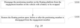
- Fig. 10 is a flow chart of a restoring method for the floating docking device of the invention. As shown in Fig. 10 , the invention further provides the restoring method for the floating docking device 1, the method mainly comprising:
Landscapes
- Engineering & Computer Science (AREA)
- Mechanical Engineering (AREA)
- Power Engineering (AREA)
- Transportation (AREA)
- Motorcycle And Bicycle Frame (AREA)
- Arrangement Or Mounting Of Propulsion Units For Vehicles (AREA)
- Manipulator (AREA)
Claims (11)
- Gleitende Andockstation (1), aufweisend eine Basis (11), einen gleitenden Abschnitt (12) und einen Positionshalteabschnitt (13),wobei der gleitende Abschnitt (12) im Verhältnis zu der Basis (11) gleitfähig ist und mit mindestens einem Positionierungselement (124) versehen ist und das Positionierungselement (124) in der Lage ist, das Andocken mit einem Eingriffselement eines Fahrzeugs mit einer auszutauschenden Batterie mittels Gleiten-Lassen des gleitenden Abschnitts (12) auszuführen, undwobei der Positionshalteabschnitt (13) dafür angeordnet ist, das Fixieren des gleitenden Abschnitts (12) im Verhältnis zu der Basis (11) zu ermöglichen,dadurch gekennzeichnet, dass der gleitende Abschnitt (12) mehrere gleitende Platten (122) und eine gleitende Plattform (121), die mit den mehreren der gleitenden Platten (122) verbunden ist, aufweist und das mindestens eine Positionierungselement (124) auf der gleitenden Plattform (121) angeordnet ist,wobei der Positionshalteabschnitt (13) mindestens einen Hochsetzmechanismus (131) entsprechend jeder der gleitenden Platten (122) aufweist und der Hochsetzmechanismus (131) in der Lage ist, zu der gleitenden Platte (122) hochgesetzt zu werden, so dass die gleitende Platte (122) im Verhältnis zu der Basis (11) fixiert wird.
- Gleitende Andockstation (1) nach Anspruch 1, dadurch gekennzeichnet, dass:jede der gleitenden Platten (122) mit mindestens einem zweiten Begrenzungselement (127) ausgestaltet ist und das zweite Begrenzungselement (127) derart angeordnet ist, dass die gleitende Platte (122) nicht in der Lage ist, sich im Verhältnis zu der Basis (11) in eine vertikale Richtung zu bewegen, undjeder der Hochsetzmechanismen (131) einen Luftzylinder (1311) und einen Reibblock (1312) aufweist, die Basis (11) mit einer Durchgangsöffnung versehen ist, der Luftzylinder (1311) fixiert mit der Basis (11) verbunden ist und ein Kolben des Luftzylinders (1311) durch die Durchgangsöffnung verläuft und mit dem Reibblock (1312) verbunden ist, so dass die gleitenden Platten (122) in der Lage sind, unter der kombinierten Einschränkung durch den Hochsetzmechanismus (131) und das zweite Begrenzungselement (127) im Verhältnis zu der Basis (11) fixiert zu werden.
- Gleitende Andockstation (1) nach Anspruch 1 oder Anspruch 2, dadurch gekennzeichnet, dass jede der gleitenden Platten (122) mit mehreren ersten Begrenzungselementen (126) ausgestaltet ist, und das erste Begrenzungselement (126) dafür angeordnet ist, der gleitenden Platte (122) das Gleiten in einer horizontalen Ebene zu gestatten.
- Gleitende Andockstation (1) nach Anspruch 3, dadurch gekennzeichnet, dass das erste Begrenzungselement (126) eine an der Basis (11) bereitgestellte Kugelrolle ist und die gleitende Platte (122) an der Kugelrolle anliegt.
- Gleitende Andockstation (1) nach Anspruch 3, dadurch gekennzeichnet, dass jede der gleitenden Platten (122) mit mehreren Stützelementen (123) versehen ist und jede der gleitenden Platten (122) über die mehreren Stützelemente (123) mit der gleitenden Plattform (121) verbunden ist.
- Gleitende Andockstation (1) nach Anspruch 5, dadurch gekennzeichnet, dass jede der gleitenden Platten (122) ferner mit mehreren Rückstellelementen (128) ausgestaltet ist und das Rückstellelement (128) zum Justieren der Position der gleitenden Platte (122) mit der gleitenden Platte (122) verbunden ist.
- Gleitende Andockstation (1) nach Anspruch 6, dadurch gekennzeichnet, dass das Rückstellelement (128) eine Feder (1281) aufweist, die Feder (1281) zwischen der Basis (11) und der gleitenden Platte (122) bereitgestellt ist und die Feder (128) dafür angeordnet ist, der gleitenden Platte (122) das Zurückkehren zu einer Position zu ermöglichen, die durch eine Vorspannkraft der Feder (1281) bestimmt ist.
- Gleitende Andockstation (1) nach Anspruch 1, dadurch gekennzeichnet, dass die gleitende Plattform (121) mit mindestens einem Arretierungs-/Freigabemechanismus (125) versehen ist und der Arretierungs-/Freigabemechanismus (125) derart angeordnet ist, dass eine Traktionsbatterie in der Lage ist, arretiert/freigegeben zu werden.
- Batterieumtauschroboter, der einen Körper (2) aufweist, der mit einer Fortbewegungsvorrichtung (3) und einer gleitenden Andockstation (1) versehen ist, dadurch gekennzeichnet, dass die gleitende Andockstation (1) die gleitende Andockstation (1) nach einem der Ansprüche 1 bis 8 ist.
- Andockverfahren für die gleitende Andockstation (1) nach einem der Ansprüche 1 bis 8, dadurch gekennzeichnet, dass das Andockverfahren Folgendes umfasst:Andocken des Positionierungselements (124) an dem Eingriffselement undFixieren des gleitenden Abschnitts (12) gegenüber der Basis (11) nach dem Andocken des Positionierungselemente an dem Eingriffselement.
- Rückstellverfahren für die gleitende Andockstation nach einem der Ansprüche 6 bis 8, dadurch gekennzeichnet, dass das Rückstellverfahren Folgendes umfasst:Lösen des Positionierungselements von dem Eingriffselement undRückstellen des gleitenden Abschnitts (12) mit, vor oder nach dem Lösen des Positionierungselements von dem Eingriffselement.
Applications Claiming Priority (2)
| Application Number | Priority Date | Filing Date | Title |
|---|---|---|---|
| CN201711064658.9A CN107719331B (zh) | 2017-11-02 | 2017-11-02 | 浮动对接装置、换电机器人、对接方法和复位方法 |
| PCT/CN2018/074805 WO2019085303A1 (zh) | 2017-11-02 | 2018-01-31 | 浮动对接装置、换电机器人、对接方法和复位方法 |
Publications (3)
| Publication Number | Publication Date |
|---|---|
| EP3705358A1 EP3705358A1 (de) | 2020-09-09 |
| EP3705358A4 EP3705358A4 (de) | 2021-08-25 |
| EP3705358B1 true EP3705358B1 (de) | 2024-11-20 |
Family
ID=61222335
Family Applications (1)
| Application Number | Title | Priority Date | Filing Date |
|---|---|---|---|
| EP18873297.8A Active EP3705358B1 (de) | 2017-11-02 | 2018-01-31 | Aufhängungsbasierte verbindungsvorrichtung, batteriewechselroboter, verbindungsverfahren und rücksetzverfahren |
Country Status (4)
| Country | Link |
|---|---|
| EP (1) | EP3705358B1 (de) |
| CN (1) | CN107719331B (de) |
| TW (2) | TWM578663U (de) |
| WO (1) | WO2019085303A1 (de) |
Families Citing this family (37)
| Publication number | Priority date | Publication date | Assignee | Title |
|---|---|---|---|---|
| CN108556609B (zh) * | 2018-04-09 | 2020-10-23 | 上海蔚来汽车有限公司 | 浮动侧向力消除机构 |
| CN109501760B (zh) * | 2018-04-10 | 2022-06-03 | 蔚来控股有限公司 | 浮动装置、换电设备和换电站 |
| CN110884383A (zh) * | 2018-09-07 | 2020-03-17 | 蔚来汽车有限公司 | 换电装置 |
| CN109501778B (zh) * | 2018-10-30 | 2024-04-26 | 蔚来(安徽)控股有限公司 | 电池转运系统、车辆换电系统及车辆换电方法 |
| CN110001599B (zh) * | 2018-12-06 | 2022-12-02 | 蔚来(安徽)控股有限公司 | 换电平台、换电机器人及充换电站 |
| CN109927682B (zh) * | 2018-12-18 | 2023-02-21 | 蔚来控股有限公司 | 定位装置以及定位方法 |
| CN110406504B (zh) * | 2019-06-27 | 2020-12-25 | 博众精工科技股份有限公司 | 基于浮动平台的电池拆卸方法 |
| CN110371088B (zh) * | 2019-06-27 | 2024-06-25 | 博众精工科技股份有限公司 | 具有无侧向力浮动的换电移载装置 |
| CN110329219A (zh) * | 2019-06-27 | 2019-10-15 | 博众精工科技股份有限公司 | 一种用于换电平台的浮动机构、浮动平台 |
| CN110329220B (zh) * | 2019-06-27 | 2024-04-23 | 博众精工科技股份有限公司 | 一种无侧向力的浮动平台 |
| CN110356373B (zh) * | 2019-06-27 | 2024-06-25 | 博众精工科技股份有限公司 | 一种侧向力消除机构 |
| CN110435605B (zh) * | 2019-06-27 | 2021-01-08 | 博众精工科技股份有限公司 | 一种用于换电的浮动平台侧向力消除方法 |
| CN110435604B (zh) * | 2019-06-27 | 2021-04-16 | 博众精工科技股份有限公司 | 一种电池组件浮动安装方法 |
| CN110316163B (zh) * | 2019-06-27 | 2024-02-27 | 博众精工科技股份有限公司 | 一种二次周转式充电仓及换电站 |
| CN110696782B (zh) * | 2019-09-05 | 2021-06-22 | 浙江吉智新能源汽车科技有限公司 | 一种具有浮动功能的换电装置 |
| CN110509756B (zh) * | 2019-09-12 | 2024-08-02 | 博众精工科技股份有限公司 | 一种变距解锁机构、换电平台 |
| CN110562214B (zh) * | 2019-09-12 | 2024-06-25 | 博众精工科技股份有限公司 | 一种浮动切换机构、浮动换电平台 |
| CN112519627B (zh) * | 2019-09-17 | 2023-03-10 | 杭州海康机器人股份有限公司 | Agv的电池更换方法及换电站 |
| CN110834914B (zh) * | 2019-12-16 | 2024-10-11 | 天津航天机电设备研究所 | 浮动式对接结构 |
| CN111301217A (zh) * | 2020-04-02 | 2020-06-19 | 昆山迈征自动化科技有限公司 | 用于新能源汽车的电动换电池装置 |
| CN113707987B (zh) * | 2020-05-06 | 2023-11-24 | 博众精工科技股份有限公司 | 一种用于车辆电池的消防箱、电池仓机构及换电系统 |
| CN111660865A (zh) * | 2020-05-15 | 2020-09-15 | 宁波江宸智能装备股份有限公司 | 一种顶升定位防错装置 |
| CN113783006B (zh) * | 2020-06-09 | 2022-11-11 | 华为技术有限公司 | 一种具有多单板对接的计算机设备和机框 |
| JP7062729B2 (ja) | 2020-08-06 | 2022-05-06 | 本田技研工業株式会社 | 燃料電池用部材の製造方法及びその装置 |
| CN114126311B (zh) * | 2020-08-31 | 2025-08-22 | 中兴通讯股份有限公司 | 线缆连接结构、单板组件、单板组件连接结构 |
| CN111960083B (zh) * | 2020-09-18 | 2025-07-08 | 浙江汉信科技有限公司 | 一种移动式粉体送料设备及送料方法 |
| CN112455278B (zh) * | 2020-10-30 | 2022-10-18 | 武汉瑞杰特材料有限责任公司 | 一种换电移载小车 |
| CN112477680B (zh) * | 2020-11-20 | 2023-06-23 | 浙江吉利控股集团有限公司 | 一种车辆换电装置、双浮动吊装换电站及换电系统 |
| CN112498278B (zh) * | 2020-11-24 | 2022-07-05 | 上海能辉科技股份有限公司 | 一种防错式重卡电池与电插头对接系统 |
| CN112477575B (zh) * | 2020-11-30 | 2022-05-03 | 浙江吉利控股集团有限公司 | 一种电池箱固定装置及车辆 |
| CN113524112B (zh) * | 2021-08-27 | 2024-09-06 | 宁波舜宇贝尔机器人有限公司 | 一种agv顶升装配用浮动合装台 |
| CN113954108B (zh) * | 2021-09-16 | 2023-08-11 | 三一锂能有限公司 | 抓手装置及换电装置 |
| CN115972971A (zh) * | 2021-10-14 | 2023-04-18 | 比亚迪股份有限公司 | 轨道交通车辆自动换电控制方法、设备、车辆和系统 |
| CN115284947B (zh) * | 2021-12-02 | 2024-12-17 | 奥动新能源汽车科技有限公司 | 具有校平功能的换电机器人及包含其的换电站 |
| CN115139994A (zh) * | 2022-08-22 | 2022-10-04 | 邵云烽 | 一种新能源汽车用更换电池夹具 |
| CN115179908A (zh) * | 2022-09-06 | 2022-10-14 | 徐工集团工程机械股份有限公司建设机械分公司 | 换电车 |
| CN119975084B (zh) * | 2025-03-14 | 2025-09-02 | 江西江新造船有限公司 | 一种船舶电池组快速更换平台 |
Family Cites Families (15)
| Publication number | Priority date | Publication date | Assignee | Title |
|---|---|---|---|---|
| US4227463A (en) * | 1978-03-27 | 1980-10-14 | Pflow Industries, Inc. | Apparatus for removing and installing batteries |
| US6098775A (en) * | 1997-12-23 | 2000-08-08 | Warner Electric Technology, Inc. | Spud locking assembly for a pneumatically actuated clutch/brake |
| EP2463162B1 (de) * | 2010-12-07 | 2016-03-30 | Carbike GmbH | System zur Energieversorgung von Elektrofahrzeugen |
| JP5794636B2 (ja) * | 2012-02-20 | 2015-10-14 | 本田技研工業株式会社 | 電動車両用電源装置の端子台 |
| JP5897924B2 (ja) * | 2012-02-20 | 2016-04-06 | 日本電産サンキョー株式会社 | バッテリー交換ロボット |
| CN104045022B (zh) * | 2013-03-15 | 2017-10-27 | 北京科易动力科技有限公司 | 一种能自动复位的浮动平台 |
| US10513247B2 (en) * | 2013-06-19 | 2019-12-24 | Tesla, Inc. | Battery swapping system and techniques |
| CN205452693U (zh) * | 2015-12-31 | 2016-08-10 | 上海电巴新能源科技有限公司 | 一种乘用车浮动式平面连接器 |
| CN206432475U (zh) * | 2016-09-09 | 2017-08-22 | 上海电巴新能源科技有限公司 | 一种浮动电连接器 |
| CN206254981U (zh) * | 2016-11-17 | 2017-06-16 | 蔚来汽车有限公司 | 悬挂式电池存储单元 |
| CN206307626U (zh) * | 2016-11-17 | 2017-07-07 | 蔚来汽车有限公司 | 无线穿梭式换电小车 |
| CN106926825B (zh) * | 2016-11-17 | 2019-10-15 | 蔚来汽车有限公司 | 用于换电设备的浮动对准装置和方法 |
| CN206231369U (zh) * | 2016-11-17 | 2017-06-09 | 蔚来汽车有限公司 | 用于换电设备的浮动对准装置 |
| CN107097067B (zh) * | 2017-06-02 | 2023-08-08 | 上海蔚来汽车有限公司 | 自动加解锁装置、换电机器人、充换电站及加解锁方法 |
| CN207496653U (zh) * | 2017-11-02 | 2018-06-15 | 蔚来汽车有限公司 | 浮动对接装置、换电机器人 |
-
2017
- 2017-11-02 CN CN201711064658.9A patent/CN107719331B/zh active Active
-
2018
- 2018-01-31 EP EP18873297.8A patent/EP3705358B1/de active Active
- 2018-01-31 WO PCT/CN2018/074805 patent/WO2019085303A1/zh not_active Ceased
- 2018-11-01 TW TW107214910U patent/TWM578663U/zh not_active IP Right Cessation
- 2018-11-01 TW TW107138846A patent/TW201929337A/zh unknown
Also Published As
| Publication number | Publication date |
|---|---|
| TWM578663U (zh) | 2019-06-01 |
| EP3705358A4 (de) | 2021-08-25 |
| EP3705358A1 (de) | 2020-09-09 |
| WO2019085303A1 (zh) | 2019-05-09 |
| CN107719331A (zh) | 2018-02-23 |
| TW201929337A (zh) | 2019-07-16 |
| CN107719331B (zh) | 2021-05-25 |
Similar Documents
| Publication | Publication Date | Title |
|---|---|---|
| EP3705358B1 (de) | Aufhängungsbasierte verbindungsvorrichtung, batteriewechselroboter, verbindungsverfahren und rücksetzverfahren | |
| CN207496653U (zh) | 浮动对接装置、换电机器人 | |
| CN107959144B (zh) | 浮动对接装置、换电机器人以及加锁、解锁和加解锁方法 | |
| EP3705355B1 (de) | Rückstellmechanismus für eine schwebende batteriewechselvorrichtung, schwebende batteriewechselvorrichtung, und batteriewechselverfahren | |
| EP4234314B1 (de) | Fahrzeugbatteriewechselvorrichtung, duale schwimmende hubbatteriewechselstation und batteriewechselsystem | |
| CN207868423U (zh) | 浮动对接装置、换电机器人 | |
| CN102673535B (zh) | 车辆电池更换设备 | |
| US10513247B2 (en) | Battery swapping system and techniques | |
| WO2013144955A2 (en) | Battery switch module | |
| CN111907367A (zh) | 一种换电平台及换电系统 | |
| CN115285078B (zh) | 一种换电站 | |
| CN118907023A (zh) | 换电设备 | |
| CN112455275B (zh) | Agv的定位机构及定位方法 | |
| CN109969146B (zh) | 移动式换电装置以及移动式换电装置组合 | |
| CN217374218U (zh) | 一种换电站用换电小车 | |
| CN112440812A (zh) | 一种电动汽车换电装置 | |
| CN117507929A (zh) | 电动卡车换电系统及换电方法 | |
| CN114889479A (zh) | 加解锁控制方法、系统、介质、装置及充换电站 | |
| CN109941238B (zh) | 车辆承载组件、承载装置、换电平台和车辆换电操作方法 | |
| CN116923174B (zh) | 换电车辆的底盘式电池安装方法、系统、设备及介质 | |
| HK1251205A1 (zh) | 浮动对接装置、换电机器人、对接方法和复位方法 | |
| CN116512890A (zh) | 一种电池锁止机构、车辆换电系统及换电方法 | |
| HK1251205B (zh) | 浮动对接装置、换电机器人、对接方法和复位方法 | |
| CN210000300U (zh) | 车辆承载组件、承载装置和换电平台 | |
| CN116923178A (zh) | 换电车辆的底盘式换电方法、系统、设备及存储介质 |
Legal Events
| Date | Code | Title | Description |
|---|---|---|---|
| STAA | Information on the status of an ep patent application or granted ep patent |
Free format text: STATUS: THE INTERNATIONAL PUBLICATION HAS BEEN MADE |
|
| PUAI | Public reference made under article 153(3) epc to a published international application that has entered the european phase |
Free format text: ORIGINAL CODE: 0009012 |
|
| STAA | Information on the status of an ep patent application or granted ep patent |
Free format text: STATUS: REQUEST FOR EXAMINATION WAS MADE |
|
| 17P | Request for examination filed |
Effective date: 20200602 |
|
| AK | Designated contracting states |
Kind code of ref document: A1 Designated state(s): AL AT BE BG CH CY CZ DE DK EE ES FI FR GB GR HR HU IE IS IT LI LT LU LV MC MK MT NL NO PL PT RO RS SE SI SK SM TR |
|
| AX | Request for extension of the european patent |
Extension state: BA ME |
|
| RAP1 | Party data changed (applicant data changed or rights of an application transferred) |
Owner name: NIO (ANHUI) HOLDING CO., LTD. |
|
| RIN1 | Information on inventor provided before grant (corrected) |
Inventor name: CHEN, JIONG Inventor name: ZHOU, XIAOHONG Inventor name: HAO, ZHANDUO |
|
| DAV | Request for validation of the european patent (deleted) | ||
| DAX | Request for extension of the european patent (deleted) | ||
| REG | Reference to a national code |
Ref country code: DE Ref legal event code: R079 Free format text: PREVIOUS MAIN CLASS: B60S0005060000 Ipc: B60L0053800000 Ref country code: DE Ref legal event code: R079 Ref document number: 602018076829 Country of ref document: DE Free format text: PREVIOUS MAIN CLASS: B60S0005060000 Ipc: B60L0053800000 |
|
| A4 | Supplementary search report drawn up and despatched |
Effective date: 20210726 |
|
| RIC1 | Information provided on ipc code assigned before grant |
Ipc: B60L 53/80 20190101AFI20210720BHEP Ipc: B60L 53/35 20190101ALI20210720BHEP Ipc: B60S 5/06 20190101ALI20210720BHEP |
|
| GRAP | Despatch of communication of intention to grant a patent |
Free format text: ORIGINAL CODE: EPIDOSNIGR1 |
|
| STAA | Information on the status of an ep patent application or granted ep patent |
Free format text: STATUS: GRANT OF PATENT IS INTENDED |
|
| INTG | Intention to grant announced |
Effective date: 20240618 |
|
| GRAS | Grant fee paid |
Free format text: ORIGINAL CODE: EPIDOSNIGR3 |
|
| GRAA | (expected) grant |
Free format text: ORIGINAL CODE: 0009210 |
|
| STAA | Information on the status of an ep patent application or granted ep patent |
Free format text: STATUS: THE PATENT HAS BEEN GRANTED |
|
| AK | Designated contracting states |
Kind code of ref document: B1 Designated state(s): AL AT BE BG CH CY CZ DE DK EE ES FI FR GB GR HR HU IE IS IT LI LT LU LV MC MK MT NL NO PL PT RO RS SE SI SK SM TR |
|
| REG | Reference to a national code |
Ref country code: GB Ref legal event code: FG4D |
|
| REG | Reference to a national code |
Ref country code: CH Ref legal event code: EP |
|
| REG | Reference to a national code |
Ref country code: DE Ref legal event code: R096 Ref document number: 602018076829 Country of ref document: DE |
|
| REG | Reference to a national code |
Ref country code: IE Ref legal event code: FG4D |
|
| REG | Reference to a national code |
Ref country code: LT Ref legal event code: MG9D |
|
| REG | Reference to a national code |
Ref country code: NL Ref legal event code: MP Effective date: 20241120 |
|
| PG25 | Lapsed in a contracting state [announced via postgrant information from national office to epo] |
Ref country code: HR Free format text: LAPSE BECAUSE OF FAILURE TO SUBMIT A TRANSLATION OF THE DESCRIPTION OR TO PAY THE FEE WITHIN THE PRESCRIBED TIME-LIMIT Effective date: 20241120 Ref country code: PT Free format text: LAPSE BECAUSE OF FAILURE TO SUBMIT A TRANSLATION OF THE DESCRIPTION OR TO PAY THE FEE WITHIN THE PRESCRIBED TIME-LIMIT Effective date: 20250320 Ref country code: IS Free format text: LAPSE BECAUSE OF FAILURE TO SUBMIT A TRANSLATION OF THE DESCRIPTION OR TO PAY THE FEE WITHIN THE PRESCRIBED TIME-LIMIT Effective date: 20250320 |
|
| PG25 | Lapsed in a contracting state [announced via postgrant information from national office to epo] |
Ref country code: NL Free format text: LAPSE BECAUSE OF FAILURE TO SUBMIT A TRANSLATION OF THE DESCRIPTION OR TO PAY THE FEE WITHIN THE PRESCRIBED TIME-LIMIT Effective date: 20241120 Ref country code: FI Free format text: LAPSE BECAUSE OF FAILURE TO SUBMIT A TRANSLATION OF THE DESCRIPTION OR TO PAY THE FEE WITHIN THE PRESCRIBED TIME-LIMIT Effective date: 20241120 |
|
| REG | Reference to a national code |
Ref country code: AT Ref legal event code: MK05 Ref document number: 1743294 Country of ref document: AT Kind code of ref document: T Effective date: 20241120 |
|
| PG25 | Lapsed in a contracting state [announced via postgrant information from national office to epo] |
Ref country code: BG Free format text: LAPSE BECAUSE OF FAILURE TO SUBMIT A TRANSLATION OF THE DESCRIPTION OR TO PAY THE FEE WITHIN THE PRESCRIBED TIME-LIMIT Effective date: 20241120 |
|
| PG25 | Lapsed in a contracting state [announced via postgrant information from national office to epo] |
Ref country code: ES Free format text: LAPSE BECAUSE OF FAILURE TO SUBMIT A TRANSLATION OF THE DESCRIPTION OR TO PAY THE FEE WITHIN THE PRESCRIBED TIME-LIMIT Effective date: 20241120 |
|
| PG25 | Lapsed in a contracting state [announced via postgrant information from national office to epo] |
Ref country code: NO Free format text: LAPSE BECAUSE OF FAILURE TO SUBMIT A TRANSLATION OF THE DESCRIPTION OR TO PAY THE FEE WITHIN THE PRESCRIBED TIME-LIMIT Effective date: 20250220 |
|
| PG25 | Lapsed in a contracting state [announced via postgrant information from national office to epo] |
Ref country code: LV Free format text: LAPSE BECAUSE OF FAILURE TO SUBMIT A TRANSLATION OF THE DESCRIPTION OR TO PAY THE FEE WITHIN THE PRESCRIBED TIME-LIMIT Effective date: 20241120 Ref country code: AT Free format text: LAPSE BECAUSE OF FAILURE TO SUBMIT A TRANSLATION OF THE DESCRIPTION OR TO PAY THE FEE WITHIN THE PRESCRIBED TIME-LIMIT Effective date: 20241120 Ref country code: GR Free format text: LAPSE BECAUSE OF FAILURE TO SUBMIT A TRANSLATION OF THE DESCRIPTION OR TO PAY THE FEE WITHIN THE PRESCRIBED TIME-LIMIT Effective date: 20250221 |
|
| PG25 | Lapsed in a contracting state [announced via postgrant information from national office to epo] |
Ref country code: PL Free format text: LAPSE BECAUSE OF FAILURE TO SUBMIT A TRANSLATION OF THE DESCRIPTION OR TO PAY THE FEE WITHIN THE PRESCRIBED TIME-LIMIT Effective date: 20241120 |
|
| PG25 | Lapsed in a contracting state [announced via postgrant information from national office to epo] |
Ref country code: RS Free format text: LAPSE BECAUSE OF FAILURE TO SUBMIT A TRANSLATION OF THE DESCRIPTION OR TO PAY THE FEE WITHIN THE PRESCRIBED TIME-LIMIT Effective date: 20250220 |
|
| PG25 | Lapsed in a contracting state [announced via postgrant information from national office to epo] |
Ref country code: SM Free format text: LAPSE BECAUSE OF FAILURE TO SUBMIT A TRANSLATION OF THE DESCRIPTION OR TO PAY THE FEE WITHIN THE PRESCRIBED TIME-LIMIT Effective date: 20241120 |
|
| PG25 | Lapsed in a contracting state [announced via postgrant information from national office to epo] |
Ref country code: DK Free format text: LAPSE BECAUSE OF FAILURE TO SUBMIT A TRANSLATION OF THE DESCRIPTION OR TO PAY THE FEE WITHIN THE PRESCRIBED TIME-LIMIT Effective date: 20241120 |
|
| PG25 | Lapsed in a contracting state [announced via postgrant information from national office to epo] |
Ref country code: EE Free format text: LAPSE BECAUSE OF FAILURE TO SUBMIT A TRANSLATION OF THE DESCRIPTION OR TO PAY THE FEE WITHIN THE PRESCRIBED TIME-LIMIT Effective date: 20241120 |
|
| PG25 | Lapsed in a contracting state [announced via postgrant information from national office to epo] |
Ref country code: RO Free format text: LAPSE BECAUSE OF FAILURE TO SUBMIT A TRANSLATION OF THE DESCRIPTION OR TO PAY THE FEE WITHIN THE PRESCRIBED TIME-LIMIT Effective date: 20241120 |
|
| PG25 | Lapsed in a contracting state [announced via postgrant information from national office to epo] |
Ref country code: SK Free format text: LAPSE BECAUSE OF FAILURE TO SUBMIT A TRANSLATION OF THE DESCRIPTION OR TO PAY THE FEE WITHIN THE PRESCRIBED TIME-LIMIT Effective date: 20241120 |
|
| PG25 | Lapsed in a contracting state [announced via postgrant information from national office to epo] |
Ref country code: CZ Free format text: LAPSE BECAUSE OF FAILURE TO SUBMIT A TRANSLATION OF THE DESCRIPTION OR TO PAY THE FEE WITHIN THE PRESCRIBED TIME-LIMIT Effective date: 20241120 |
|
| PG25 | Lapsed in a contracting state [announced via postgrant information from national office to epo] |
Ref country code: IT Free format text: LAPSE BECAUSE OF FAILURE TO SUBMIT A TRANSLATION OF THE DESCRIPTION OR TO PAY THE FEE WITHIN THE PRESCRIBED TIME-LIMIT Effective date: 20241120 |
|
| REG | Reference to a national code |
Ref country code: DE Ref legal event code: R097 Ref document number: 602018076829 Country of ref document: DE |
|
| REG | Reference to a national code |
Ref country code: CH Ref legal event code: PL |
|
| PG25 | Lapsed in a contracting state [announced via postgrant information from national office to epo] |
Ref country code: SE Free format text: LAPSE BECAUSE OF FAILURE TO SUBMIT A TRANSLATION OF THE DESCRIPTION OR TO PAY THE FEE WITHIN THE PRESCRIBED TIME-LIMIT Effective date: 20241120 |
|
| PG25 | Lapsed in a contracting state [announced via postgrant information from national office to epo] |
Ref country code: LU Free format text: LAPSE BECAUSE OF NON-PAYMENT OF DUE FEES Effective date: 20250131 Ref country code: MC Free format text: LAPSE BECAUSE OF FAILURE TO SUBMIT A TRANSLATION OF THE DESCRIPTION OR TO PAY THE FEE WITHIN THE PRESCRIBED TIME-LIMIT Effective date: 20241120 |
|
| PLBE | No opposition filed within time limit |
Free format text: ORIGINAL CODE: 0009261 |
|
| STAA | Information on the status of an ep patent application or granted ep patent |
Free format text: STATUS: NO OPPOSITION FILED WITHIN TIME LIMIT |
|
| PG25 | Lapsed in a contracting state [announced via postgrant information from national office to epo] |
Ref country code: BE Free format text: LAPSE BECAUSE OF NON-PAYMENT OF DUE FEES Effective date: 20250131 |
|
| PG25 | Lapsed in a contracting state [announced via postgrant information from national office to epo] |
Ref country code: CH Free format text: LAPSE BECAUSE OF NON-PAYMENT OF DUE FEES Effective date: 20250131 |
|
| 26N | No opposition filed |
Effective date: 20250821 |
|
| REG | Reference to a national code |
Ref country code: BE Ref legal event code: MM Effective date: 20250131 |
|
| PG25 | Lapsed in a contracting state [announced via postgrant information from national office to epo] |
Ref country code: IE Free format text: LAPSE BECAUSE OF NON-PAYMENT OF DUE FEES Effective date: 20250131 |
|
| PGFP | Annual fee paid to national office [announced via postgrant information from national office to epo] |
Ref country code: GB Payment date: 20260123 Year of fee payment: 9 |
|
| PGFP | Annual fee paid to national office [announced via postgrant information from national office to epo] |
Ref country code: DE Payment date: 20260121 Year of fee payment: 9 |
|
| PGFP | Annual fee paid to national office [announced via postgrant information from national office to epo] |
Ref country code: FR Payment date: 20260123 Year of fee payment: 9 |