EP3704440B1 - Aide au réglage, assemblage de connecteurs sans fil et procédé de surveillance d'une position - Google Patents
Aide au réglage, assemblage de connecteurs sans fil et procédé de surveillance d'une position Download PDFInfo
- Publication number
- EP3704440B1 EP3704440B1 EP19813320.9A EP19813320A EP3704440B1 EP 3704440 B1 EP3704440 B1 EP 3704440B1 EP 19813320 A EP19813320 A EP 19813320A EP 3704440 B1 EP3704440 B1 EP 3704440B1
- Authority
- EP
- European Patent Office
- Prior art keywords
- electrode
- component
- electrodes
- evaluation
- adjustment
- Prior art date
- Legal status (The legal status is an assumption and is not a legal conclusion. Google has not performed a legal analysis and makes no representation as to the accuracy of the status listed.)
- Active
Links
Images




Classifications
-
- A—HUMAN NECESSITIES
- A61—MEDICAL OR VETERINARY SCIENCE; HYGIENE
- A61B—DIAGNOSIS; SURGERY; IDENTIFICATION
- A61B5/00—Measuring for diagnostic purposes; Identification of persons
- A61B5/68—Arrangements of detecting, measuring or recording means, e.g. sensors, in relation to patient
- A61B5/6846—Arrangements of detecting, measuring or recording means, e.g. sensors, in relation to patient specially adapted to be brought in contact with an internal body part, i.e. invasive
- A61B5/6847—Arrangements of detecting, measuring or recording means, e.g. sensors, in relation to patient specially adapted to be brought in contact with an internal body part, i.e. invasive mounted on an invasive device
- A61B5/686—Permanently implanted devices, e.g. pacemakers, other stimulators, biochips
-
- A—HUMAN NECESSITIES
- A61—MEDICAL OR VETERINARY SCIENCE; HYGIENE
- A61N—ELECTROTHERAPY; MAGNETOTHERAPY; RADIATION THERAPY; ULTRASOUND THERAPY
- A61N1/00—Electrotherapy; Circuits therefor
- A61N1/18—Applying electric currents by contact electrodes
- A61N1/32—Applying electric currents by contact electrodes alternating or intermittent currents
- A61N1/36—Applying electric currents by contact electrodes alternating or intermittent currents for stimulation
- A61N1/362—Heart stimulators
- A61N1/37—Monitoring; Protecting
-
- A—HUMAN NECESSITIES
- A61—MEDICAL OR VETERINARY SCIENCE; HYGIENE
- A61B—DIAGNOSIS; SURGERY; IDENTIFICATION
- A61B5/00—Measuring for diagnostic purposes; Identification of persons
- A61B5/06—Devices, other than using radiation, for detecting or locating foreign bodies ; Determining position of diagnostic devices within or on the body of the patient
- A61B5/065—Determining position of the probe employing exclusively positioning means located on or in the probe, e.g. using position sensors arranged on the probe
- A61B5/068—Determining position of the probe employing exclusively positioning means located on or in the probe, e.g. using position sensors arranged on the probe using impedance sensors
-
- A—HUMAN NECESSITIES
- A61—MEDICAL OR VETERINARY SCIENCE; HYGIENE
- A61B—DIAGNOSIS; SURGERY; IDENTIFICATION
- A61B5/00—Measuring for diagnostic purposes; Identification of persons
- A61B5/68—Arrangements of detecting, measuring or recording means, e.g. sensors, in relation to patient
- A61B5/6846—Arrangements of detecting, measuring or recording means, e.g. sensors, in relation to patient specially adapted to be brought in contact with an internal body part, i.e. invasive
- A61B5/6867—Arrangements of detecting, measuring or recording means, e.g. sensors, in relation to patient specially adapted to be brought in contact with an internal body part, i.e. invasive specially adapted to be attached or implanted in a specific body part
- A61B5/6877—Nerve
-
- A—HUMAN NECESSITIES
- A61—MEDICAL OR VETERINARY SCIENCE; HYGIENE
- A61N—ELECTROTHERAPY; MAGNETOTHERAPY; RADIATION THERAPY; ULTRASOUND THERAPY
- A61N1/00—Electrotherapy; Circuits therefor
- A61N1/18—Applying electric currents by contact electrodes
- A61N1/32—Applying electric currents by contact electrodes alternating or intermittent currents
- A61N1/36—Applying electric currents by contact electrodes alternating or intermittent currents for stimulation
- A61N1/372—Arrangements in connection with the implantation of stimulators
- A61N1/37211—Means for communicating with stimulators
- A61N1/37235—Aspects of the external programmer
- A61N1/37241—Aspects of the external programmer providing test stimulations
-
- G—PHYSICS
- G01—MEASURING; TESTING
- G01B—MEASURING LENGTH, THICKNESS OR SIMILAR LINEAR DIMENSIONS; MEASURING ANGLES; MEASURING AREAS; MEASURING IRREGULARITIES OF SURFACES OR CONTOURS
- G01B7/00—Measuring arrangements characterised by the use of electric or magnetic techniques
- G01B7/30—Measuring arrangements characterised by the use of electric or magnetic techniques for measuring angles or tapers; for testing the alignment of axes
- G01B7/31—Measuring arrangements characterised by the use of electric or magnetic techniques for measuring angles or tapers; for testing the alignment of axes for testing the alignment of axes
-
- A—HUMAN NECESSITIES
- A61—MEDICAL OR VETERINARY SCIENCE; HYGIENE
- A61B—DIAGNOSIS; SURGERY; IDENTIFICATION
- A61B2560/00—Constructional details of operational features of apparatus; Accessories for medical measuring apparatus
- A61B2560/04—Constructional details of apparatus
- A61B2560/0443—Modular apparatus
- A61B2560/045—Modular apparatus with a separable interface unit, e.g. for communication
-
- A—HUMAN NECESSITIES
- A61—MEDICAL OR VETERINARY SCIENCE; HYGIENE
- A61B—DIAGNOSIS; SURGERY; IDENTIFICATION
- A61B2562/00—Details of sensors; Constructional details of sensor housings or probes; Accessories for sensors
- A61B2562/04—Arrangements of multiple sensors of the same type
- A61B2562/043—Arrangements of multiple sensors of the same type in a linear array
-
- A—HUMAN NECESSITIES
- A61—MEDICAL OR VETERINARY SCIENCE; HYGIENE
- A61B—DIAGNOSIS; SURGERY; IDENTIFICATION
- A61B2562/00—Details of sensors; Constructional details of sensor housings or probes; Accessories for sensors
- A61B2562/04—Arrangements of multiple sensors of the same type
- A61B2562/046—Arrangements of multiple sensors of the same type in a matrix array
-
- A—HUMAN NECESSITIES
- A61—MEDICAL OR VETERINARY SCIENCE; HYGIENE
- A61N—ELECTROTHERAPY; MAGNETOTHERAPY; RADIATION THERAPY; ULTRASOUND THERAPY
- A61N1/00—Electrotherapy; Circuits therefor
- A61N1/02—Details
- A61N1/08—Arrangements or circuits for monitoring, protecting, controlling or indicating
-
- A—HUMAN NECESSITIES
- A61—MEDICAL OR VETERINARY SCIENCE; HYGIENE
- A61N—ELECTROTHERAPY; MAGNETOTHERAPY; RADIATION THERAPY; ULTRASOUND THERAPY
- A61N1/00—Electrotherapy; Circuits therefor
- A61N1/18—Applying electric currents by contact electrodes
- A61N1/32—Applying electric currents by contact electrodes alternating or intermittent currents
- A61N1/36—Applying electric currents by contact electrodes alternating or intermittent currents for stimulation
- A61N1/372—Arrangements in connection with the implantation of stimulators
- A61N1/375—Constructional arrangements, e.g. casings
- A61N1/3752—Details of casing-lead connections
Definitions
- the present invention relates to an alignment aid, a wireless electrical connector assembly, particularly for use with implantable components, and an associated method for monitoring the position of a first component and a second component with respect to one another.
- AIMD active implantable medical devices
- connectors which are integrated in the cables, make it possible to separate the individual parts. This not only makes implantation easier, but also makes it possible to replace defective, improved or used parts (e.g. the battery in a pacemaker, which only has a lifespan of 3 to 7 years).
- Percutaneous cables are often sufficient for power delivery and signal transmission during acute procedures. This is avoided in chronic applications since percutaneous cables pose a serious risk of inflammation.
- a wireless transcutaneous transmission system For chronic applications it is preferable to use a wireless transcutaneous transmission system. Examples of such systems are cochlear implants or the so-called Brindley stimulator (bladder pacemaker), which usually use inductive coupling both for the energy supply and for signal transmission on one or more coupling channels.
- Resistive or capacitive coupling through the skin is another alternative.
- a Stimulus Router System known in which Stimulating current is provided via self-adhesive surface electrodes that are stuck to the skin.
- a subcutaneous receiving electrode receives this signal and transmits it to the stimulation site via implanted leads.
- This concept can be extended to multi-channel applications, where a surface array of electrodes is capacitively coupled to an implanted subcutaneous counterpart in an identical geometric arrangement. Each pair of electrodes then forms a capacitively coupled entity and forms a channel.
- alignment of the external component with respect to the implanted component is essential to ensure sufficient accuracy and efficiency in both energy delivery and energy transfer.
- EP 2 661 162 A2 discloses a device with one or more plug-in units.
- a device with at least one plug-in unit and a base body device for receiving the plug-in unit is presented.
- the plug-in unit comprises an electrically conductive structure having at least one surface area capable of forming a capacitive coupling with a surface area of an electrically conductive part of the body device when the plug-in unit is inserted into the body device.
- the device further comprises a monitoring circuit for generating a signal indicative of the electrical properties of a measuring circuit comprising the capacitive coupling and at least one galvanic contact which is provided by electrical connectors of the slide-in unit and the main body device.
- the generated signal is also an indicator of the correctness of the installation of the plug-in unit. In this way, the correct installation of the plug-in unit can be indicated and monitored electrically.
- EP 1 763 078 A1 refers to a system for measuring alignment between chips.
- this document discloses an alignment measurement system for measuring the alignment between a plurality of chips of a device under test, the chips being assembled in a three-dimensional stack configuration and equipped with at least one integrated capacitive sensor.
- the system includes a multi-capacitor structure integrated in the capacitive sensor, at least one sensor circuit connected to the multi-capacitor structure that outputs an output voltage that is proportional to a change in a capacitive value of the multi-capacitor structure of the integrated capacitive sensor of the device under test and a measured offset between chips corresponds to the device under test.
- EP 0 240 020 A2 discloses a capacitive transducer for position measurement.
- the capacitive transducer for position measurement has a first scale and a second scale which are arranged adjacent to each other so that they can be moved relative to each other.
- Both scales are provided with either transmission electrodes or reception electrodes, both of which consist of groups of electrodes arranged in the direction in which the scales are relatively movable and capacitively coupled to each other.
- the aforesaid transmission electrodes constitute a group of transmission electrodes to which a number of AC signals of different phases are supplied, and the aforesaid receiving electrodes consist of a number of electrodes with an equally spaced pitch obtained by dividing the transmission wavelength pitch of the aforesaid group of transmission electrodes by a predetermined integer becomes.
- a scale accuracy of the size of a fraction of the receiving electrode pitch corresponding to the number of transmitting electrodes in the aforementioned group of transmitting electrodes is thereby possible.
- monitoring is of crucial importance for multi-channel applications. While misalignments can be compensated for in inductive systems by using larger external coils, this approach is often limited by the miniaturization of the implant and an increasing risk of crosstalk between the channels.
- the present invention sets itself the task of specifying an adjustment aid for aligning at least one first and one second component with respect to one another, which allows even densely packed contact arrays to be connected reliably and with a precise fit.
- the adjustment aid should be as inexpensive as possible and, moreover, biocompatible and certifiable for chronic use. Long-term monitoring of correct alignment should also be possible.
- the present invention is based on the idea that an external excitation signal is applied to a first electrode, preferably located outside. The signal is then coupled to an implanted counter-electrode, for example, from where it is transmitted to at least one other electrode via an electrical connection. From there the excitation signal is coupled back to the external unit and the electrical response is measured. When there is misalignment of the external unit with respect to the corresponding, e.g. implanted, array, the coupling impedances increase and the detectable electrical response drops.
- the present invention provides an alignment aid for aligning at least a first and a second component with respect to one another.
- the adjustment aid has a first adjustment electrode arrangement, which has at least one excitation electrode and at least one evaluation electrode and can be arranged on the first component.
- a second adjustment electrode arrangement is provided, which has at least one receiving electrode and at least one transmitting electrode and can be arranged on the second component.
- a control and evaluation circuit is connected to the first adjustment electrode arrangement, wherein the control and evaluation circuit can be operated to feed the excitation electrode with an excitation voltage and to pick off a measurement signal at the evaluation electrode, which depends on a degree of coverage of the first and second adjustment electrode arrangement.
- the excitation electrode can (alternately) also function as an evaluation electrode and accordingly the implantable pendant can function both as a receiving and as a transmitting electrode. In this way, for example, inhomogeneities occurring in time or space can be compensated. For example, electrode 1 picks up at time t1 while electrodes 2 and 3 evaluate. At time t2, electrode 2 picks up while electrodes 1 and 3 evaluate, etc.
- the arrangement according to the invention has the advantage that it can be produced easily and inexpensively and in particular the electrode arrangements can be produced without additional effort together with the electrically conductive structures of the first and second components that are present anyway.
- the adjustment electrode arrangements take up very little space. This advantage comes into play in particular in the case of implanted arrangements.
- an easy-to-integrate active monitoring of the alignment of two components with respect to one another can be provided, whereby one of the two components can be completely electrically passive. Since the input signal and the measured output signal are only applied to or tapped from one of the two components, the adjustment aid can also be used in places that are difficult to access, or if the layer in between (e.g. the skin) must not be damaged. Finally, the adjustment aid according to the present invention can also be integrated into existing systems.
- the excitation electrode and the receiving electrode are aligned to overlap one another to form a supply capacitor, and the transmitting electrode and the evaluation electrode are aligned to overlap one another to form a measuring capacitor.
- a capacitive coupling has the advantage that no ohmic contact is required.
- the electrically conductive coupling electrodes do not have to be opened, ie an insulating layer of material can remain on them.
- This can e.g. B. from polymers (Parylene-C, PDMS), oxides (TiOx) or other materials.
- Parylene-C for example, is an approved material for human implants and is electrically dense at a thickness of 10 ⁇ m.
- silicone rubber polydimethylsiloxane, PDMS
- PDMS polydimethylsiloxane
- the at least one receiving electrode and the at least one transmitting electrode are electrically conductively connected to one another.
- the measuring circuit can be closed in a particularly simple manner.
- the at least one receiving electrode and the at least one transmitting electrode can also be coupled in a different way, for example capacitively via comb structures or inductively.
- the first adjustment electrode arrangement has a first planar electrode array
- the second adjustment electrode arrangement has a second planar electrode array, which is arranged in a plane parallel to the first planar electrode array, if the first and second components with are adjusted in relation to each other.
- the alignment aid is compatible with planar connectors, such as are frequently used for electrical contacting of AIMD.
- the first adjustment electrode arrangement has two evaluation electrodes which are arranged in such a way that their (imaginary) connecting lines with the excitation electrode intersect at an angle other than 0°
- the second adjustment electrode arrangement has two transmission electrodes which are arranged in such a way that their connection lines with the receiving electrode intersect at an angle other than 0°.
- the third evaluation electrode which is arranged on the (imaginary) connecting line between the second evaluation electrode and the excitation electrode, with the second adjustment electrode arrangement having a corresponding third transmission electrode which is on the Connecting line between the second transmitting electrode and the receiving electrode is arranged.
- the third evaluation electrode is preferably not arranged between the second evaluation electrode and the excitation electrode, but outside.
- the excitation electrode and the evaluation electrodes as well as the receiving electrode and the transmitting electrodes can be arranged equidistantly.
- the electrode shape can be chosen arbitrarily.
- the excitation electrode and the evaluation electrodes as well as the receiving electrode and the transmitting electrode preferably have circular and/or elliptical and/or polygonal metallization structures. This can be done in a particularly simple manner, e.g. B. produce by photo structuring or laser structuring.
- the present invention further relates to a wireless connector assembly having a first and a second component and having an alignment aid according to any one of the preceding claims, wherein at least the second component is implantable, and wherein the first Component carries a first alignment electrode assembly and the second component carries a second alignment electrode assembly.
- the adjustment aid can be used advantageously if the first component has an implantable coupling electrode array and the second component has an external coupling electrode array which makes electrical contact with the implantable coupling electrode array in the implanted state.
- Such coupling electrode arrays can, for example, also work on the capacitive principle and are z. B. in the German patent application DE 10 2018 219 831 A1 described.
- the alignment aid according to the present invention can also be used with coaxial connectors, e.g. B. with a pacemaker, but also with any other implantable systems that have and control a stimulation electrode (without recording), such as deep brain stimulators, vagus nerve stimulators, peripheral nerve stimulators, etc., with the first component having an implantable coaxial connector and the second component having an implantable one Has mating coaxial connector.
- the first component is a coaxial socket of a cardiac pacemaker and the second component is the coaxial plug of a stimulation electrode.
- pacemakers there is usually no way of checking whether the stimulation electrode is actually connected to the header of the actual device.
- the fact that the connector of the stimulation electrode has come loose from the header leads to the failure of the stimulation and thus to the complete (life-threatening) failure of the pacemaker.
- a misalignment between the header and the stimulation electrode connector can already be detected when stimulation signals are still being transmitted to the stimulation electrode, and appropriate countermeasures can be initiated in good time.
- the method can also provide for the position of the first component and the second component to be changed in relation to one another until the measurement voltage exceeds the preset threshold value.
- control and evaluation circuit generates a warning signal when the measurement voltage is below the preset threshold value.
- a warning signal is particularly advantageous when used with a chronically implanted device such as a cardiac pacemaker.
- figure 1 shows a perspective view of the adjustment aid 100 in the connected state.
- a first adjustment electrode arrangement 102 is located on an outer side 104 of the skin 106.
- a second adjustment electrode arrangement 108 is arranged on the inner side 110 of the skin 106.
- the first alignment electrode assembly 102 and the second alignment electrode assembly 108 may be parts of a connector that electrically contacts and powers an active implanted medical system (AIMD) through the skin.
- AIMD active implanted medical system
- the principles of the present invention can also be applied to other applications where two parts that are moveable with respect to each other need to be precisely aligned with each other and one of the two parts no longer needs to be aligned after the alignment electrode assembly has been attached is readily accessible.
- the second alignment electrode assembly 108 is stationarily implanted in the interior 110 under the skin 106, while the first alignment electrode assembly 102 is slidable, as symbolized by the dashed elements.
- the implanted second alignment electrode assembly 108 includes three electrically connected electrodes that form a similar structure to the first alignment electrode assembly 102 .
- the first alignment electrode assembly 102 has three corresponding unconnected electrodes on the external unit.
- an excitation electrode 112 which outputs an excitation signal 116 to the corresponding receiving electrode 114 .
- the excitation signal 116 is capacitively transmitted through the skin 106 to the implanted counter electrode 114 .
- the excitation signal is transmitted to two transmitting electrodes 120A, 120B via electrical connections 118A, 118B. From there, a signal is coupled out, again capacitively, to two corresponding evaluation electrodes 122A, 122B arranged in the outer area 104 .
- the electrical response which can be picked off at the evaluation electrodes 122, forms a measurement signal 124.
- the coupling impedance Z increases both between the excitation and reception electrodes (Z in ) and between the transmission and evaluation electrodes (Z out ). These impedance increases result in a decrease in electrical response.
- a shift ⁇ X can be inferred. With appropriate calibration, it is also possible to make quantitative statements about the shift ⁇ X.
- the adjustment aid 100 can, of course, also have other electrode geometries than those shown in figure 1 have shown. Any arrangement with more than two pairs of electrodes is possible. Two pairs of electrodes must be provided as a minimum, but more than two can be used to monitor multiple degrees of freedom simultaneously.
- the respective corresponding electrodes are advantageously of the same size and shape. Of course, this is not absolutely necessary, however, since only the overlap of the mutually opposite electrodes is included in the measurement signal, and the desired measurement signal can be defined by appropriate calibration steps in the case of an optimal adjustment.
- compliance with the optimal adjustment can be monitored by measuring the electrical response on two transmission channels.
- the electrical response is proportional to the changes in the coupling impedance. For example, frequencies greater than 1 kHz and low voltages in the range of about 1.2 V can be used to prevent nerve pathways or receptors located in the skin 106 from being stimulated.
- the alignment aid 100 according to the present invention can be easily placed in the vicinity of a stimulating or recording electrode.
- the present configuration offers the possibility of simultaneously monitoring linear displacements within a plane as well as rotational deviations around any axis.
- electrodes forming planar coil assemblies can also be used in addition to or in place of capacitive electrodes.
- the coupling electrodes can be formed by alloys such as platinum-iridium or MP35N® .
- MP35N ® is a registered trademark of Standard Pressed Steel Technologies, Inc.
- the ingredients in MP35N ® provide the alloy with excellent corrosion resistance because all four alloying ingredients nickel, cobalt, chromium and molybdenum provide corrosion resistance in nearly all industrial stainless steel, Increase nickel and cobalt alloys.
- the 20% chromium content improves resistance to oxidation, sulfidation and chemical reactions with salt at elevated temperatures.
- Any other electrically conductive electrode material can of course also be used. However, only materials that are not ferromagnetic should be used for MRI examinations.
- FIG 12 shows an implantable capacitive coupling connector 128 which may be implanted, for example, under the skin and connect to a multi-channel pacing electrode array or other AIMD (not shown in the figures).
- a complementary mating connector 126 is operatively placed in close proximity to connector 128 such that the plurality of first coupling electrodes 130 with the corresponding plurality of second coupling electrodes 132 enable capacitively coupled signal transmission.
- an adjustment aid is provided, which is figure 2 embodiment shown is reduced to its simplest components.
- the implantable connector 128 has a receiving electrode 114 and a transmitting electrode 120 .
- the receiving electrode 114 and the transmitting electrode 120 are connected to one another via an electrically conductive connection 118, for example a metalized conductor track.
- the associated first adjustment electrode arrangement which is arranged on the connector 126, comprises an excitation electrode 112 and an evaluation electrode 122.
- a control and evaluation circuit (not visible in the figures) is provided in order to monitor the adjustment of the two connectors 126, 128 with respect to one another.
- an excitation signal is applied to the excitation electrode 112 .
- This is capacitively received through the skin by the receiving electrode 114 and forwarded to the transmitting electrode 120 via the electrical connection 118 .
- the signal in turn reaches the evaluation electrode 122 capacitively through the skin the first and the second connector 126, 128 are no longer sufficiently well aligned, one or both of the capacitive coupling paths lose contact in whole or in part and only a weakened measurement signal or no measurement signal at all can be received at the evaluation electrode 122.
- the electrodes can be formed by alloys such as platinum-iridium or MP35N® .
- An electrically insulating passivation layer is provided for electrical insulation and protection against the external environment.
- the first connector 126 and/or the second connector 128 includes an electrically insulating substrate 134 .
- the substrate material of both connectors can be flexible or rigid depending on the design, but should not be electrically conductive. In the case of electrically conductive material, additional insulation layers must be introduced. For example, polyimide, PDMS, ceramics and all other materials that are used for electrical circuit carriers are suitable.
- the coupling electrodes 130, 132 end in connection areas 140, 142 to which an external circuit or a stimulation electrode can be connected.
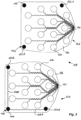
- the connector assembly 138 is shown with another embodiment of the alignment aid that is generally of the L-shaped configuration 1 is equivalent to.
- the implanted second alignment electrode assembly 108 includes three electrodes electrically connected together forming an L-shaped structure.
- the first alignment electrode assembly 102 has three corresponding unconnected electrodes on the external unit 126 .
- an excitation electrode 112 which outputs an excitation signal 116 to the corresponding receiving electrode 114 .
- the excitation signal 116 is capacitively transmitted through the skin 106 to the implanted counter electrode 114 .
- the excitation signal is transmitted to two transmitting electrodes 120A, 120B via electrical connections 118A, 118B. From there, a signal is coupled out, again capacitively, to two corresponding evaluation electrodes 122A, 122B arranged on the connector 126 .
- the electrical response that can be picked off at the evaluation electrodes 122 forms a measurement signal.
- the coupling impedance increases both between the excitation and receiving electrodes and between the transmitting and evaluation electrodes. These impedance increases result in a decrease in electrical response.
- evaluating the measurement signals which can be picked off at the evaluation electrodes 122A, 122B, a shift or rotation can be inferred. With appropriate calibration, it is also possible to make quantitative statements about the misalignment between the two connectors 126, 128.
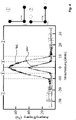
- the figures 4 and 5 show measurement results obtained with the L-shaped arrangement from the figures 1 and 3 can be obtained using ultrapure water as a model for the skin.
- the ratio of the measured output signal to the input excitation signal is plotted as a function of a linear shift.
- the curve 401 shows measurement results for an adjustment aid in which the electrodes have a circular shape with a diameter of 5 mm.
- Curve 402 shows the corresponding results for circular electrodes with a diameter of 10 mm.
- both curves 401, 402 have their maximum with an optimal alignment (i.e. no displacement between the first and the second adjustment electrode arrangement and therefore maximum overlap).
- the losses are lower with a larger electrode area, so that a higher output signal can be measured, i. H. the maximum is closer to the ideal value of 1.
- the ratio decreases with increasing displacement between the first and the second alignment electrode arrangement (area 1).
- both curves 401, 402 fall to the minimum base value when the overlap between the first and the second adjustment electrode arrangement is no longer present (area 2).
- the constant base value is due to resistive leakage paths.
- the behavior shown also exhibits rotational symmetry.
- Figure 12 illustrates the results for a pure rotation about a pivot point 505 located at the center of the hypotenuse of the isosceles triangle formed by the L-shaped electrodes.
- the curves 501 and 502 each indicate separately the signals of the evaluation electrodes for an adjustment aid in which the electrodes have a circular shape with a diameter of 5 mm.
- Curves 503 and 504 show the corresponding results for circular electrodes with a diameter of 10 mm.
- the electrodes can also be rectangular, oval, triangular or have any other suitable outline shape.
- the measuring frequency used in these tests was 1 MHz. However, the frequency is not expected to have a significant impact on the measurement results and any suitable frequency range for the excitation signals can be used. The best results are expected with frequencies between 1 kHz and 1 MHz.
- the adjustment aid 100 has a first adjustment electrode arrangement 102 and a second adjustment electrode arrangement 108.
- the second adjustment electrode arrangement 108 is implanted.
- a third evaluation electrode 122C and a corresponding third transmission electrode 120C are provided in addition to the excitation electrode 112 and the two evaluation electrodes 122A and 122B.
- the evaluation electrodes are equidistant with a distance a on imaginary connecting lines, which intersect in the excitation electrode 112 and the receiving electrode 114, respectively.
- the excitation electrode 112 and corresponding receiving electrode 114 preferably have a circular shape.
- the transmission electrodes 120A to 120C and the evaluation electrodes 122A to 122C preferably have an elliptical shape.
- the long axis of the ellipse may measure 10mm while the short axis measures 5mm. In this way, a distinction can be made between a shift in the X direction and a shift in the Y direction.
- FIG 8 shows a multi-channel connector for a stimulation implant 800, in which the adjustment aid according to the present invention can also be used advantageously.
- the adjustment aid can be used with a pacemaker, but also with any other implantable systems that have and control a stimulation electrode (without recording), such as deep brain stimulators, vagus nerve stimulators, peripheral nerve stimulators, etc.
- the stimulation implant 800 usually has a so-called header 802, in which the electrical connections 804 for the stimulation electrode are arranged.
- an excitation electrode 812 and at least one evaluation electrode 822 can be provided in this coaxial connector arrangement in addition to the connections 804 .
- a receiving electrode 814 and a transmitting electrode 820 connected to it are provided on the connector 805, which, as symbolized by the arrow 803, leads to the stimulation electrode (not shown in the figures) in addition to the counter-contacts 806.
- the electrical connection 818 is preferably made inside the stimulation electrode connection 805.
- the excitation electrode 812 is supplied with an excitation signal, which is received by the receiving electrode 814 in the plugged-in state.
- the signal is transmitted to the transmitting electrode 820 via the electrical connection 818 and coupled to the evaluation electrode 822 in a capacitive manner.
- the stimulation implant 800 can correspondingly read out a measurement signal 824 when the connector 805 is satisfactorily adjusted on the header 802. In the event that the connection has become loose, the measurement signal 824 falls below a specified threshold value. The stimulation implant 800 can then generate and output an alarm signal, for example.
- control and evaluation electronics 807 contained in the stimulation implant can generate and output an alarm signal. A potential failure can therefore be detected in good time.
- the present invention is able to provide a robust and precise system for monitoring correct alignment, with which linear and rotational misalignment of two electrode arrangements arranged opposite one another can be detected. Since the implanted structures according to the present invention act as transceivers, the excitation and evaluation can be performed outside the body, so that the system according to the invention can be integrated in any arrangement in which direct feedback is not possible. In addition, the present invention is of course not limited to the adjustment of external to implanted electrode arrays, but can be used wherever an adjustment has to be monitored and only one of the two partners can be directly electrically contacted.
Landscapes
- Health & Medical Sciences (AREA)
- Life Sciences & Earth Sciences (AREA)
- Engineering & Computer Science (AREA)
- Public Health (AREA)
- Biomedical Technology (AREA)
- Veterinary Medicine (AREA)
- Animal Behavior & Ethology (AREA)
- General Health & Medical Sciences (AREA)
- Heart & Thoracic Surgery (AREA)
- Physics & Mathematics (AREA)
- Pathology (AREA)
- Biophysics (AREA)
- Medical Informatics (AREA)
- Molecular Biology (AREA)
- Surgery (AREA)
- Radiology & Medical Imaging (AREA)
- Nuclear Medicine, Radiotherapy & Molecular Imaging (AREA)
- Cardiology (AREA)
- General Physics & Mathematics (AREA)
- Human Computer Interaction (AREA)
- Electrotherapy Devices (AREA)
Claims (13)
- Agencement de connecteurs sans fil comprenant au moins des premier et second composants et une aide au réglage (100), dans lequel au moins le second composant peut être implanté, dans lequel l'aide au réglage (100) pour orienter les au moins un premier et second composants l'un par rapport à l'autre comprend :un premier agencement d'électrodes de réglage (102), qui présente au moins une électrode d'excitation (112) et au moins une électrode d'évaluation (122) et est disposé sur le premier composant,un second agencement d'électrodes de réglage (108) qui présente au moins une électrode de réception (114) et au moins une électrode d'émission (120) et qui disposé sur le second composant,un circuit de commande et d'évaluation, qui est connecté au premier agencement d'électrodes de réglage (102), dans lequel le circuit de commande et d'évaluation peut être actionné pour alimenter l'électrode d'excitation (112) avec une tension d'excitation (116) et pour prélever au niveau de l'électrode d'évaluation (122) un signal de mesure (124) qui dépend d'un degré de recouvrement des premier et second agencements d'électrodes de réglage.
- Agencement de connecteurs sans fil selon la revendication 1, dans lequel, dans l'état réglé de manière optimale des premier et second composants l'un par rapport à l'autre, l'électrode d'excitation (112) et l'électrode de réception (114) sont orientées de manière à se chevaucher l'une l'autre pour former un condensateur d'alimentation, et l'électrode d'émission (120) et l'électrode d'évaluation (122) sont orientées de manière à se chevaucher l'une l'autre pour former un condensateur de mesure.
- Agencement de connecteurs sans fil selon la revendication 1 ou 2, dans lequel la au moins une électrode de réception (114) et la au moins une électrode d'émission (120) sont connectées électriquement de manière conductrice l'une à l'autre.
- Agencement de connecteurs sans fil selon l'une quelconque des revendications précédentes, dans lequel le premier agencement d'électrodes de réglage (102) comprend un premier réseau d'électrodes planaires et le second agencement d'électrodes de réglage (108) comprend un second réseau d'électrodes planaires agencé dans un plan parallèle au premier réseau d'électrodes planaires lorsque les premier et second composants sont réglés l'un par rapport à l'autre.
- Agencement de connecteurs sans fil selon l'une quelconque des revendications précédentes, dans lequel le premier agencement d'électrodes de réglage (102) comprend deux électrodes d'évaluation (122A, 122B) qui sont agencées de telle sorte que leurs lignes de connexion avec l'électrode d'excitation (112) se recoupent l'une l'autre selon un angle différent de 0°, et dans lequel le second ensemble d'électrodes de réglage (108) comprend deux électrodes d'émission (120A, 120B) agencées de telle sorte que leurs lignes de connexion avec l'électrode de réception (114) se recoupent l'une l'autre selon un angle différent de 0°.
- Agencement de connecteurs sans fil selon la revendication 5, comprenant en outre une troisième électrode d'évaluation (120C) agencée sur la ligne de connexion de la deuxième électrode d'évaluation et de l'électrode d'excitation, dans lequel le second agencement d'électrodes de réglage (102) comprend une troisième électrode d'émission correspondante (120C) agencée sur la ligne de connexion entre la deuxième électrode d'émission et l'électrode de réception.
- Agencement de connecteurs sans fil selon la revendication 6, dans lequel l'électrode d'excitation (112) et les électrodes d'évaluation (122) ainsi que l'électrode de réception (114) et les électrodes d'émission (120) sont agencées de manière équidistante.
- Agencement de connecteurs sans fil selon l'une quelconque des revendications précédentes, dans lequel l'électrode d'excitation (112) et les électrodes d'évaluation (122) ainsi que l'électrode de réception (114) et l'électrode d'émission (120) présentent des structures de métallisation circulaires et/ou elliptiques et/ou polygonales.
- Agencement de connecteurs sans fil selon l'une quelconque des revendications 1 à 8, dans lequel le second composant comprend un réseau d'électrodes de couplage implantable, et le premier composant comprend un réseau d'électrodes de couplage externe qui met en contact électriquement le réseau d'électrodes de couplage implantable à l'état implanté.
- Agencement de connecteurs sans fil selon l'une quelconque des revendications 1 à 8, dans lequel le premier composant comprend un connecteur coaxial implantable et le second composant comprend un connecteur coaxial implantable.
- Agencement de connecteurs sans fil selon la revendication 10, dans lequel le premier composant est une douille coaxiale (802) d'un implant de stimulation (800) et le second composant est le connecteur coaxial (805) d'une électrode de stimulation.
- Procédé de surveillance de la position d'un premier composant et d'un second composant l'un par rapport à l'autre, le procédé utilisant un agencement de connecteurs sans fil selon l'une quelconque des revendications 1 à 8, le premier composant n'étant pas implantable, le procédé comprenant les étapes consistant à :appliquer une tension d'excitation (116) à la au moins une électrode d'excitation (112), prélever une tension de mesure (124) au niveau de la au moins une électrode d'évaluation (122),comparer la tension de mesure (124) avec une valeur de seuil préréglée,modifier la position du premier composant par rapport au second composant jusqu'à ce que la tension de mesure (124) dépasse la valeur de seuil prédéfinie.
- Procédé selon la revendication 12, dans lequel le circuit de commande et d'évaluation génère un signal d'avertissement lorsque la tension de mesure (124) est inférieure à la valeur de seuil prédéfinie.
Applications Claiming Priority (2)
| Application Number | Priority Date | Filing Date | Title |
|---|---|---|---|
| DE102019200740.6A DE102019200740A1 (de) | 2019-01-22 | 2019-01-22 | Justierhilfe, drahtlose Verbinderanordnung und Verfahren zum Überwachen einer Position |
| PCT/EP2019/083300 WO2020151861A1 (fr) | 2019-01-22 | 2019-12-02 | Aide au réglage, assemblage de connecteurs sans fil et procédé de surveillance d'une position |
Publications (2)
| Publication Number | Publication Date |
|---|---|
| EP3704440A1 EP3704440A1 (fr) | 2020-09-09 |
| EP3704440B1 true EP3704440B1 (fr) | 2023-03-22 |
Family
ID=68762753
Family Applications (1)
| Application Number | Title | Priority Date | Filing Date |
|---|---|---|---|
| EP19813320.9A Active EP3704440B1 (fr) | 2019-01-22 | 2019-12-02 | Aide au réglage, assemblage de connecteurs sans fil et procédé de surveillance d'une position |
Country Status (4)
| Country | Link |
|---|---|
| US (1) | US20210346703A1 (fr) |
| EP (1) | EP3704440B1 (fr) |
| DE (1) | DE102019200740A1 (fr) |
| WO (1) | WO2020151861A1 (fr) |
Citations (1)
| Publication number | Priority date | Publication date | Assignee | Title |
|---|---|---|---|---|
| EP1763078B1 (fr) * | 2005-09-09 | 2013-04-10 | STMicroelectronics Srl | Système pour déterminer l'alignement d'un empilement des puces semi-conducteurs |
Family Cites Families (7)
| Publication number | Priority date | Publication date | Assignee | Title |
|---|---|---|---|---|
| SE411392B (sv) * | 1977-12-09 | 1979-12-17 | Inst Mikrovagsteknik Vid Tekni | Metanordning for kapacitiv bestemning av det inbordes leget hos tva relativt varandra rorliga delar |
| JPS62235504A (ja) * | 1986-04-04 | 1987-10-15 | Mitsutoyo Corp | 容量型位置測定トランスデユ−サ |
| US8543221B2 (en) * | 2011-09-22 | 2013-09-24 | Advanced Neuromodulation Systems, Inc. | External systems for detecting implantable neurostimulation leads and devices, and methods of using same |
| FI124557B (en) * | 2012-05-03 | 2014-10-15 | Tellabs Oy | Equipment with one or more plug-in units |
| DE102013108733A1 (de) * | 2013-08-12 | 2015-02-12 | Wittenstein Ag | Vorrichtung und Verfahren zur Ausrichtung einer Primäreinrichtung |
| US10617880B2 (en) * | 2015-12-08 | 2020-04-14 | Intelligent Implants Limited | System and method for an electrical implant device with increased patient compliance |
| DE102018219831A1 (de) | 2018-11-20 | 2020-05-20 | Albert-Ludwigs-Universität Freiburg | Implantierbare elektrische verbinderanordnung und implantierbare elektrodenanordnung |
-
2019
- 2019-01-22 DE DE102019200740.6A patent/DE102019200740A1/de not_active Withdrawn
- 2019-12-02 WO PCT/EP2019/083300 patent/WO2020151861A1/fr not_active Ceased
- 2019-12-02 EP EP19813320.9A patent/EP3704440B1/fr active Active
-
2021
- 2021-07-22 US US17/383,048 patent/US20210346703A1/en active Pending
Patent Citations (1)
| Publication number | Priority date | Publication date | Assignee | Title |
|---|---|---|---|---|
| EP1763078B1 (fr) * | 2005-09-09 | 2013-04-10 | STMicroelectronics Srl | Système pour déterminer l'alignement d'un empilement des puces semi-conducteurs |
Also Published As
| Publication number | Publication date |
|---|---|
| DE102019200740A8 (de) | 2020-09-17 |
| DE102019200740A1 (de) | 2020-07-23 |
| EP3704440A1 (fr) | 2020-09-09 |
| WO2020151861A1 (fr) | 2020-07-30 |
| US20210346703A1 (en) | 2021-11-11 |
Similar Documents
| Publication | Publication Date | Title |
|---|---|---|
| DE19837913C2 (de) | Implantierbare Vorrichtung mit einer eine Empfangsspule aufweisenden Ladestromeinspeiseanordnung | |
| EP3284517B1 (fr) | Implant et procédé d'identification d'une ligne d'électrodes | |
| DE202011051572U1 (de) | Elektrische Verbindungen zur Verwendung in implantierbaren medizinischen Vorrichtungen | |
| DE602005002498T2 (de) | Gehirnimplantat | |
| EP2599520A1 (fr) | Électrode destinée à être utilisée dans un dispositif médical implantable compatible IRM | |
| EP2502646B1 (fr) | Appareil implantable | |
| EP3678735B1 (fr) | Ensemble connecteur électrique implantable et ensemble électrode implantable | |
| DE102020132756B3 (de) | Ferroelektrischer Biochip | |
| DE112017007012B4 (de) | Konnektorstruktur | |
| EP2110156B1 (fr) | Elément de découplage de champs à utiliser avec une sonde implantable et appareil médical implantable | |
| DE102019200740A1 (de) | Justierhilfe, drahtlose Verbinderanordnung und Verfahren zum Überwachen einer Position | |
| EP2887860B1 (fr) | Dispositif capteur pour la détection de signaux bioélectriques | |
| EP2465569A2 (fr) | Appareil implantable | |
| EP4297678B1 (fr) | Élément de base pour dispositif électromédical et dispositif électromédical | |
| EP3284510B1 (fr) | Ligne d'electrodes, implant et procede d'identification d'une ligne d'electrodes | |
| EP3884546B1 (fr) | Agencement de liaison électrique implantable | |
| WO2008132164A1 (fr) | Électrode et connecteur enfichable pour électrode | |
| DE102019107600B4 (de) | Antennenanordnung | |
| EP4669411A1 (fr) | Agencement de circuit électrique pour interface biomédicale | |
| EP3284511B1 (fr) | Ligne d'electrodes, implant et procede d'identification d'une ligne d'electrodes | |
| EP3284508B1 (fr) | Implant et procede d'identification d'une ligne d'electrodes | |
| EP2505229A2 (fr) | Appareil implantable | |
| DE202022101060U1 (de) | Gehäuse für implantierbare Stimulatoren | |
| DE202023105728U1 (de) | Flexible Leiterbahnstruktur auf Basis TPU für Dauerimplantate | |
| EP2465571B1 (fr) | Appareil implantable |
Legal Events
| Date | Code | Title | Description |
|---|---|---|---|
| STAA | Information on the status of an ep patent application or granted ep patent |
Free format text: STATUS: UNKNOWN |
|
| STAA | Information on the status of an ep patent application or granted ep patent |
Free format text: STATUS: THE INTERNATIONAL PUBLICATION HAS BEEN MADE |
|
| PUAI | Public reference made under article 153(3) epc to a published international application that has entered the european phase |
Free format text: ORIGINAL CODE: 0009012 |
|
| STAA | Information on the status of an ep patent application or granted ep patent |
Free format text: STATUS: REQUEST FOR EXAMINATION WAS MADE |
|
| 17P | Request for examination filed |
Effective date: 20200324 |
|
| AK | Designated contracting states |
Kind code of ref document: A1 Designated state(s): AL AT BE BG CH CY CZ DE DK EE ES FI FR GB GR HR HU IE IS IT LI LT LU LV MC MK MT NL NO PL PT RO RS SE SI SK SM TR |
|
| AX | Request for extension of the european patent |
Extension state: BA ME |
|
| RIN1 | Information on inventor provided before grant (corrected) |
Inventor name: KIELE, PATRICK Inventor name: KOHLER, ALINA Inventor name: STIEGLITZ, THOMAS Inventor name: PASLUOSTA, CRISTIAN |
|
| RIN1 | Information on inventor provided before grant (corrected) |
Inventor name: STIEGLITZ, THOMAS Inventor name: KOHLER, ALINA Inventor name: KIELE, PATRICK Inventor name: PASLUOSTA, CRISTIAN |
|
| DAV | Request for validation of the european patent (deleted) | ||
| DAX | Request for extension of the european patent (deleted) | ||
| REG | Reference to a national code |
Ref country code: DE Ref legal event code: R079 Ref document number: 502019007299 Country of ref document: DE Free format text: PREVIOUS MAIN CLASS: G01B0007000000 Ipc: G01B0007310000 |
|
| GRAP | Despatch of communication of intention to grant a patent |
Free format text: ORIGINAL CODE: EPIDOSNIGR1 |
|
| STAA | Information on the status of an ep patent application or granted ep patent |
Free format text: STATUS: GRANT OF PATENT IS INTENDED |
|
| RIC1 | Information provided on ipc code assigned before grant |
Ipc: A61N 1/375 20060101ALN20220914BHEP Ipc: A61N 1/08 20060101ALN20220914BHEP Ipc: A61B 5/00 20060101ALI20220914BHEP Ipc: A61B 5/24 20210101ALI20220914BHEP Ipc: G01B 7/31 20060101AFI20220914BHEP |
|
| INTG | Intention to grant announced |
Effective date: 20221004 |
|
| RIC1 | Information provided on ipc code assigned before grant |
Ipc: A61N 1/375 20060101ALN20220923BHEP Ipc: A61N 1/08 20060101ALN20220923BHEP Ipc: A61B 5/00 20060101ALI20220923BHEP Ipc: A61B 5/24 20210101ALI20220923BHEP Ipc: G01B 7/31 20060101AFI20220923BHEP |
|
| GRAS | Grant fee paid |
Free format text: ORIGINAL CODE: EPIDOSNIGR3 |
|
| GRAA | (expected) grant |
Free format text: ORIGINAL CODE: 0009210 |
|
| STAA | Information on the status of an ep patent application or granted ep patent |
Free format text: STATUS: THE PATENT HAS BEEN GRANTED |
|
| AK | Designated contracting states |
Kind code of ref document: B1 Designated state(s): AL AT BE BG CH CY CZ DE DK EE ES FI FR GB GR HR HU IE IS IT LI LT LU LV MC MK MT NL NO PL PT RO RS SE SI SK SM TR |
|
| REG | Reference to a national code |
Ref country code: GB Ref legal event code: FG4D Free format text: NOT ENGLISH |
|
| REG | Reference to a national code |
Ref country code: CH Ref legal event code: EP |
|
| REG | Reference to a national code |
Ref country code: DE Ref legal event code: R096 Ref document number: 502019007299 Country of ref document: DE |
|
| REG | Reference to a national code |
Ref country code: IE Ref legal event code: FG4D Free format text: LANGUAGE OF EP DOCUMENT: GERMAN |
|
| REG | Reference to a national code |
Ref country code: AT Ref legal event code: REF Ref document number: 1555550 Country of ref document: AT Kind code of ref document: T Effective date: 20230415 |
|
| REG | Reference to a national code |
Ref country code: LT Ref legal event code: MG9D |
|
| REG | Reference to a national code |
Ref country code: NL Ref legal event code: MP Effective date: 20230322 |
|
| PG25 | Lapsed in a contracting state [announced via postgrant information from national office to epo] |
Ref country code: RS Free format text: LAPSE BECAUSE OF FAILURE TO SUBMIT A TRANSLATION OF THE DESCRIPTION OR TO PAY THE FEE WITHIN THE PRESCRIBED TIME-LIMIT Effective date: 20230322 Ref country code: NO Free format text: LAPSE BECAUSE OF FAILURE TO SUBMIT A TRANSLATION OF THE DESCRIPTION OR TO PAY THE FEE WITHIN THE PRESCRIBED TIME-LIMIT Effective date: 20230622 Ref country code: LV Free format text: LAPSE BECAUSE OF FAILURE TO SUBMIT A TRANSLATION OF THE DESCRIPTION OR TO PAY THE FEE WITHIN THE PRESCRIBED TIME-LIMIT Effective date: 20230322 Ref country code: LT Free format text: LAPSE BECAUSE OF FAILURE TO SUBMIT A TRANSLATION OF THE DESCRIPTION OR TO PAY THE FEE WITHIN THE PRESCRIBED TIME-LIMIT Effective date: 20230322 Ref country code: HR Free format text: LAPSE BECAUSE OF FAILURE TO SUBMIT A TRANSLATION OF THE DESCRIPTION OR TO PAY THE FEE WITHIN THE PRESCRIBED TIME-LIMIT Effective date: 20230322 |
|
| PG25 | Lapsed in a contracting state [announced via postgrant information from national office to epo] |
Ref country code: SE Free format text: LAPSE BECAUSE OF FAILURE TO SUBMIT A TRANSLATION OF THE DESCRIPTION OR TO PAY THE FEE WITHIN THE PRESCRIBED TIME-LIMIT Effective date: 20230322 Ref country code: NL Free format text: LAPSE BECAUSE OF FAILURE TO SUBMIT A TRANSLATION OF THE DESCRIPTION OR TO PAY THE FEE WITHIN THE PRESCRIBED TIME-LIMIT Effective date: 20230322 Ref country code: GR Free format text: LAPSE BECAUSE OF FAILURE TO SUBMIT A TRANSLATION OF THE DESCRIPTION OR TO PAY THE FEE WITHIN THE PRESCRIBED TIME-LIMIT Effective date: 20230623 Ref country code: FI Free format text: LAPSE BECAUSE OF FAILURE TO SUBMIT A TRANSLATION OF THE DESCRIPTION OR TO PAY THE FEE WITHIN THE PRESCRIBED TIME-LIMIT Effective date: 20230322 |
|
| PG25 | Lapsed in a contracting state [announced via postgrant information from national office to epo] |
Ref country code: SM Free format text: LAPSE BECAUSE OF FAILURE TO SUBMIT A TRANSLATION OF THE DESCRIPTION OR TO PAY THE FEE WITHIN THE PRESCRIBED TIME-LIMIT Effective date: 20230322 Ref country code: RO Free format text: LAPSE BECAUSE OF FAILURE TO SUBMIT A TRANSLATION OF THE DESCRIPTION OR TO PAY THE FEE WITHIN THE PRESCRIBED TIME-LIMIT Effective date: 20230322 Ref country code: PT Free format text: LAPSE BECAUSE OF FAILURE TO SUBMIT A TRANSLATION OF THE DESCRIPTION OR TO PAY THE FEE WITHIN THE PRESCRIBED TIME-LIMIT Effective date: 20230724 Ref country code: ES Free format text: LAPSE BECAUSE OF FAILURE TO SUBMIT A TRANSLATION OF THE DESCRIPTION OR TO PAY THE FEE WITHIN THE PRESCRIBED TIME-LIMIT Effective date: 20230322 Ref country code: EE Free format text: LAPSE BECAUSE OF FAILURE TO SUBMIT A TRANSLATION OF THE DESCRIPTION OR TO PAY THE FEE WITHIN THE PRESCRIBED TIME-LIMIT Effective date: 20230322 |
|
| PG25 | Lapsed in a contracting state [announced via postgrant information from national office to epo] |
Ref country code: SK Free format text: LAPSE BECAUSE OF FAILURE TO SUBMIT A TRANSLATION OF THE DESCRIPTION OR TO PAY THE FEE WITHIN THE PRESCRIBED TIME-LIMIT Effective date: 20230322 Ref country code: PL Free format text: LAPSE BECAUSE OF FAILURE TO SUBMIT A TRANSLATION OF THE DESCRIPTION OR TO PAY THE FEE WITHIN THE PRESCRIBED TIME-LIMIT Effective date: 20230322 Ref country code: IS Free format text: LAPSE BECAUSE OF FAILURE TO SUBMIT A TRANSLATION OF THE DESCRIPTION OR TO PAY THE FEE WITHIN THE PRESCRIBED TIME-LIMIT Effective date: 20230722 |
|
| REG | Reference to a national code |
Ref country code: DE Ref legal event code: R097 Ref document number: 502019007299 Country of ref document: DE |
|
| PLBE | No opposition filed within time limit |
Free format text: ORIGINAL CODE: 0009261 |
|
| STAA | Information on the status of an ep patent application or granted ep patent |
Free format text: STATUS: NO OPPOSITION FILED WITHIN TIME LIMIT |
|
| PG25 | Lapsed in a contracting state [announced via postgrant information from national office to epo] |
Ref country code: SI Free format text: LAPSE BECAUSE OF FAILURE TO SUBMIT A TRANSLATION OF THE DESCRIPTION OR TO PAY THE FEE WITHIN THE PRESCRIBED TIME-LIMIT Effective date: 20230322 Ref country code: DK Free format text: LAPSE BECAUSE OF FAILURE TO SUBMIT A TRANSLATION OF THE DESCRIPTION OR TO PAY THE FEE WITHIN THE PRESCRIBED TIME-LIMIT Effective date: 20230322 Ref country code: CZ Free format text: LAPSE BECAUSE OF FAILURE TO SUBMIT A TRANSLATION OF THE DESCRIPTION OR TO PAY THE FEE WITHIN THE PRESCRIBED TIME-LIMIT Effective date: 20230322 |
|
| 26N | No opposition filed |
Effective date: 20240102 |
|
| REG | Reference to a national code |
Ref country code: CH Ref legal event code: PL |
|
| PG25 | Lapsed in a contracting state [announced via postgrant information from national office to epo] |
Ref country code: LU Free format text: LAPSE BECAUSE OF NON-PAYMENT OF DUE FEES Effective date: 20231202 |
|
| PG25 | Lapsed in a contracting state [announced via postgrant information from national office to epo] |
Ref country code: MC Free format text: LAPSE BECAUSE OF FAILURE TO SUBMIT A TRANSLATION OF THE DESCRIPTION OR TO PAY THE FEE WITHIN THE PRESCRIBED TIME-LIMIT Effective date: 20230322 |
|
| REG | Reference to a national code |
Ref country code: BE Ref legal event code: MM Effective date: 20231231 |
|
| PG25 | Lapsed in a contracting state [announced via postgrant information from national office to epo] |
Ref country code: MC Free format text: LAPSE BECAUSE OF FAILURE TO SUBMIT A TRANSLATION OF THE DESCRIPTION OR TO PAY THE FEE WITHIN THE PRESCRIBED TIME-LIMIT Effective date: 20230322 Ref country code: LU Free format text: LAPSE BECAUSE OF NON-PAYMENT OF DUE FEES Effective date: 20231202 |
|
| REG | Reference to a national code |
Ref country code: IE Ref legal event code: MM4A |
|
| PG25 | Lapsed in a contracting state [announced via postgrant information from national office to epo] |
Ref country code: IE Free format text: LAPSE BECAUSE OF NON-PAYMENT OF DUE FEES Effective date: 20231202 |
|
| PG25 | Lapsed in a contracting state [announced via postgrant information from national office to epo] |
Ref country code: BE Free format text: LAPSE BECAUSE OF NON-PAYMENT OF DUE FEES Effective date: 20231231 |
|
| PG25 | Lapsed in a contracting state [announced via postgrant information from national office to epo] |
Ref country code: CH Free format text: LAPSE BECAUSE OF NON-PAYMENT OF DUE FEES Effective date: 20231231 |
|
| PG25 | Lapsed in a contracting state [announced via postgrant information from national office to epo] |
Ref country code: IE Free format text: LAPSE BECAUSE OF NON-PAYMENT OF DUE FEES Effective date: 20231202 Ref country code: CH Free format text: LAPSE BECAUSE OF NON-PAYMENT OF DUE FEES Effective date: 20231231 Ref country code: BE Free format text: LAPSE BECAUSE OF NON-PAYMENT OF DUE FEES Effective date: 20231231 |
|
| PG25 | Lapsed in a contracting state [announced via postgrant information from national office to epo] |
Ref country code: BG Free format text: LAPSE BECAUSE OF FAILURE TO SUBMIT A TRANSLATION OF THE DESCRIPTION OR TO PAY THE FEE WITHIN THE PRESCRIBED TIME-LIMIT Effective date: 20230322 |
|
| PG25 | Lapsed in a contracting state [announced via postgrant information from national office to epo] |
Ref country code: BG Free format text: LAPSE BECAUSE OF FAILURE TO SUBMIT A TRANSLATION OF THE DESCRIPTION OR TO PAY THE FEE WITHIN THE PRESCRIBED TIME-LIMIT Effective date: 20230322 |
|
| PG25 | Lapsed in a contracting state [announced via postgrant information from national office to epo] |
Ref country code: CY Free format text: LAPSE BECAUSE OF FAILURE TO SUBMIT A TRANSLATION OF THE DESCRIPTION OR TO PAY THE FEE WITHIN THE PRESCRIBED TIME-LIMIT; INVALID AB INITIO Effective date: 20191202 |
|
| PG25 | Lapsed in a contracting state [announced via postgrant information from national office to epo] |
Ref country code: HU Free format text: LAPSE BECAUSE OF FAILURE TO SUBMIT A TRANSLATION OF THE DESCRIPTION OR TO PAY THE FEE WITHIN THE PRESCRIBED TIME-LIMIT; INVALID AB INITIO Effective date: 20191202 |
|
| PG25 | Lapsed in a contracting state [announced via postgrant information from national office to epo] |
Ref country code: TR Free format text: LAPSE BECAUSE OF FAILURE TO SUBMIT A TRANSLATION OF THE DESCRIPTION OR TO PAY THE FEE WITHIN THE PRESCRIBED TIME-LIMIT Effective date: 20230322 |
|
| PGFP | Annual fee paid to national office [announced via postgrant information from national office to epo] |
Ref country code: GB Payment date: 20251218 Year of fee payment: 7 |
|
| PGFP | Annual fee paid to national office [announced via postgrant information from national office to epo] |
Ref country code: FR Payment date: 20251217 Year of fee payment: 7 |
|
| REG | Reference to a national code |
Ref country code: AT Ref legal event code: MM01 Ref document number: 1555550 Country of ref document: AT Kind code of ref document: T Effective date: 20241202 |
|
| PGFP | Annual fee paid to national office [announced via postgrant information from national office to epo] |
Ref country code: DE Payment date: 20251222 Year of fee payment: 7 |
|
| PG25 | Lapsed in a contracting state [announced via postgrant information from national office to epo] |
Ref country code: AT Free format text: LAPSE BECAUSE OF NON-PAYMENT OF DUE FEES Effective date: 20241202 |
|
| PGFP | Annual fee paid to national office [announced via postgrant information from national office to epo] |
Ref country code: AT Payment date: 20260410 Year of fee payment: 5 |
|
| PGFP | Annual fee paid to national office [announced via postgrant information from national office to epo] |
Ref country code: IT Payment date: 20251231 Year of fee payment: 7 |