EP2465571B1 - Appareil implantable - Google Patents
Appareil implantable Download PDFInfo
- Publication number
- EP2465571B1 EP2465571B1 EP11191741.5A EP11191741A EP2465571B1 EP 2465571 B1 EP2465571 B1 EP 2465571B1 EP 11191741 A EP11191741 A EP 11191741A EP 2465571 B1 EP2465571 B1 EP 2465571B1
- Authority
- EP
- European Patent Office
- Prior art keywords
- longitudinal portion
- electrode
- conductor
- medical device
- line
- Prior art date
- Legal status (The legal status is an assumption and is not a legal conclusion. Google has not performed a legal analysis and makes no representation as to the accuracy of the status listed.)
- Not-in-force
Links
Images


Classifications
-
- A—HUMAN NECESSITIES
- A61—MEDICAL OR VETERINARY SCIENCE; HYGIENE
- A61N—ELECTROTHERAPY; MAGNETOTHERAPY; RADIATION THERAPY; ULTRASOUND THERAPY
- A61N1/00—Electrotherapy; Circuits therefor
- A61N1/02—Details
- A61N1/04—Electrodes
- A61N1/05—Electrodes for implantation or insertion into the body, e.g. heart electrode
-
- A—HUMAN NECESSITIES
- A61—MEDICAL OR VETERINARY SCIENCE; HYGIENE
- A61B—DIAGNOSIS; SURGERY; IDENTIFICATION
- A61B18/00—Surgical instruments, devices or methods for transferring non-mechanical forms of energy to or from the body
- A61B18/04—Surgical instruments, devices or methods for transferring non-mechanical forms of energy to or from the body by heating
- A61B18/12—Surgical instruments, devices or methods for transferring non-mechanical forms of energy to or from the body by heating by passing a current through the tissue to be heated, e.g. high-frequency current
- A61B18/14—Probes or electrodes therefor
- A61B18/1492—Probes or electrodes therefor having a flexible, catheter-like structure, e.g. for heart ablation
-
- A—HUMAN NECESSITIES
- A61—MEDICAL OR VETERINARY SCIENCE; HYGIENE
- A61N—ELECTROTHERAPY; MAGNETOTHERAPY; RADIATION THERAPY; ULTRASOUND THERAPY
- A61N1/00—Electrotherapy; Circuits therefor
- A61N1/02—Details
- A61N1/04—Electrodes
- A61N1/05—Electrodes for implantation or insertion into the body, e.g. heart electrode
- A61N1/056—Transvascular endocardial electrode systems
-
- A—HUMAN NECESSITIES
- A61—MEDICAL OR VETERINARY SCIENCE; HYGIENE
- A61N—ELECTROTHERAPY; MAGNETOTHERAPY; RADIATION THERAPY; ULTRASOUND THERAPY
- A61N1/00—Electrotherapy; Circuits therefor
- A61N1/02—Details
- A61N1/08—Arrangements or circuits for monitoring, protecting, controlling or indicating
- A61N1/086—Magnetic resonance imaging [MRI] compatible leads
Definitions
- the invention relates to a permanently or temporarily implantable device with an elongated electrical conductor.
- Such devices such as electrode lines for electrostimulation, have the disadvantage that their electrical conductor can heat up in a magnetic resonance tomograph because the magnetic fields prevailing in the magnetic resonance tomographs induce not inconsiderable electrical currents in the electrical conductor. Therefore, cardiac pacemaker patients today can usually not be examined or only to a limited extent in a magnetic resonance tomograph.
- implantable cardiac pacemakers or defibrillators typically have at least one pacing lead connected to their proximal end for connection to the pacemaker or defibrillator with a standard electrical connection and one or more electrode poles at their distal end provided for placement in the heart.
- Such an electrode pole serves to deliver electrical impulses to the tissue (myocardium) of the heart or to sense electric fields in order to be able to sense an activity of a heart within the scope of so-called sensing.
- Electrode poles are typically provided in the form of a ring around the electrode lead having an electrically conductive surface or in the form of a tip electrode at the distal end of the electrode lead.
- the electrode poles are electrically conductively connected via one or more electrical lines to contacts of the electrical connection of the electrode line at its proximal end.
- the electrode leads extend at the proximal end thereof and the electrode poles at the distal end of the electrode lead one or more electrical leads, one or more electrically connect the electrode poles to one or more of the contacts.
- These electrical lines can be used, on the one hand, to transmit stimulation pulses to the electrode poles or to transmit electrical signals picked up by the electrode poles to the proximal end of the electrode line and are referred to as function lines in the course of the further description.
- Such functional lines are required for the functions of the respective electrode line required electrical conductors and as such the risk that in them by external alternating magnetic fields electrical currents are induced, which can lead, for example, to an undesirable heating of the function lines or the associated electrode poles.
- Electrode lines are known which can be used in environments with external alternating magnetic fields inducing electrical currents due to filters, capacitive and inductive couplings.
- the invention has for its object to provide a device which solves the problem described above.
- the electrical line of the medical device according to the invention contains a functional conductor, which has between its proximal end and a connected electrode pole line sections of preferably greatly different characteristic impedance. These attenuate and transform a contact resistance of the connected Elektrodenpols into the tissue such that a mismatch for high frequency can be achieved and thereby in the implanted state in the case of exposure to high-frequency alternating magnetic fields, as used in magnetic resonance imaging, the transmitted to the tissue performance is lowered. As a result, heating of the tissue, in particular near the electrode pole or optionally near the electrode poles, can be significantly reduced.
- the electrical lead is preferably an electrode lead for the diagnosis or therapy of cardiac activity.
- the difference between the first and second conduction wave resistance is so pronounced in embodiments of the medical device that a real part of the second conduction wave resistance for radio frequency electromagnetic waves is smaller by a factor of at least two than a real part of the first conduction wave resistance.
- this difference is even greater and the said factor is at least five, and in particularly preferred embodiments at least ten.
- the effectiveness of the second longitudinal section for reducing the active power transmitted to the tissue then increases with increasing length of the second longitudinal section.
- Particularly favorable lengths of the second longitudinal section are in the range up to a maximum of 5 d iel .
- the second longitudinal section exceeds a length of about 10 d iel , not.
- the effectiveness of the second length also depends on the degree of attenuation experienced by radio frequency waves in the transmission line. The higher the attenuation, the lower the active power at the electrode pole.
- the function conductor has an inner conductor and a hollow cylindrical outer conductor, wherein the inner conductor has a different from the inner conductor in the first longitudinal section geometric shape in the second longitudinal section.
- the inner conductor is hollow helically in the first longitudinal section of the electrical conductor and cylindrical in the second longitudinal section.
- the cylindrical second longitudinal section of the inner conductor has a larger diameter than the hollow helix of the inner conductor in the first longitudinal section. From the outer conductor, however, it should be separated by an inner dielectric, so be electrically isolated.
- This inner dielectric can be realized as a coating or film. According to the prior art, layer thicknesses down to about 100 nm or even less are possible, for example by PVD (plasma vapor deposition) or CVD (chemical vapor deposition). The thinner the layer thickness, the greater the reduction in the power transferred into the tissue. However, a very thin layer is more susceptible to mechanical stress. It could, for example, scrape or lose its electrical insulation property through scratches.
- Preferred as a compromise between electrical effect and mechanical stability is a layer thickness of 0.5 .mu.m to 2.5 .mu.m, particularly preferably 1 .mu.m.
- the inner conductor may alternatively be designed as a cable feed line in the first longitudinal section and in the form of a hollow helix in the second section.
- the invention applies to electrode leads of any type of electrode poles.
- the electrode pole can be designed, for example, as a tip electrode pole or as a ring electrode pole. It is also possible to provide a plurality of electrode poles on a function conductor.
- the electrode pole directly adjoins the second longitudinal section of the functional guide. This is manufacturing technology advantageous because the first longitudinal section does not have to be interrupted.
- it is provided to embed the second longitudinal section in the function conductor at a distance from the electrode pole, so that the second longitudinal section is surrounded in both longitudinal directions by conductor sections of the type of the first longitudinal section.
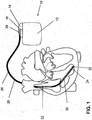
- FIG. 1 As an example of implantable medical devices, there is shown an implantable cardiac stimulator 10 and an implantable electrode lead 20 connected thereto.
- the implantable cardiac stimulator 10 may be a pacemaker or a cardioverter / defibrillator (ICD).
- the heart stimulator 10 is a ventricular pacemaker and defibrillator.
- Other known cardiac stimulators are dual chamber pacemakers for stimulation of the right atrium and right ventricle, or biventricular pacemakers, which can also stimulate the left ventricle in addition to the right ventricle.
- Such stimulators typically have a housing 12, which is usually made of metal and thus is electrically conductive and can serve as a large electrode pole.
- a terminal housing 14 is typically attached, which is also referred to as a header.
- Such a header typically has contact sockets for receiving plug contacts.
- the contact sockets have electrical contacts 16, which are connected via corresponding conductors with an arranged in the housing 12 of the heart stimulator 10 electronics.
- the electrode line 20 likewise constitutes an implantable medical device.
- electrode poles in the form of a tip or tip electrode 22 and a ring electrode 24 arranged in the vicinity thereof are arranged in a manner known per se.
- the electrode poles 22 and 24 are designed such that, depending on the function of a cardiac stimulator, to which the electrode lead 20 is connected, for sensing electrical potentials of the heart tissue (myocardium). serve or for the delivery of electrical signals, for example, for the delivery of stimulation pulses to the surrounding heart tissue, are formed.
- FIG. 1 shows how the electrode poles, so the tip electrode 22 and the ring electrode 24, in the application, the electrode line 20, located in the apex of a right ventricle of a heart.
- Both the tip electrode 22 and the ring electrode 24 are electrically connected via at least one electrical conductor 26 with a plug contact 28 at the proximal end of the electrode line 20.
- the plug contact 28 has electrical contacts which correspond to the electrical contacts 16 of the contact socket in the connection housing 14 of the implantable cardiac stimulator.
- the electrical conductors 26 may be formed in the electrode line 20 in different longitudinal sections as approximately elongated Seilzuleiter or helically coiled conductor.
- Such conductors which electrically connect functional electrode poles to electrical contacts of the plug-in contact at the proximal end of the electrode lead 20 are also referred to as function leads in the context of this text, since they transmit electrical signals from plug contact to the respective electrode pole, for example, or represent sensed electrical potentials Lead signals from each electrode pole to the plug contact and thus serve the elementary function of the medical device.
- the electrical function conductors 26, which connect the electrode poles 22 and 24, respectively, to the electrical contacts of the plug 28 of the electrode line 20, are surrounded over most of their length by an insulating sheath, so that an electrical contact to the tissue of the heart is targeted via the electrode poles comes about.
- the electrode line 20 In addition to the electrode poles 22 and 24, which typically serve the (in this case ventricular) stimulation of the heart tissue, the electrode line 20 also has two larger-area electrode poles 30 and 32, which serve as defibrillation electrodes and are formed by at least one bare helix-like coiled wire ,
- an ablation electrode lead can in principle also be used, which likewise projects into the heart of a patient in the application and which is controlled by a device arranged outside the patient and is connected to it for this purpose.
- electrode lines can be used with customary adaptation to the special requirements of the respective field of application also for stimulation and derivation of signals to nerves, brain, and other organs or for the supply of implantable sensors.
- FIG. 2 shows an equivalent circuit diagram of a functional conductor of an electrode lead according to the prior art.
- the function conductor 26 'forms with its longitudinal extent L a first line impedance Z 0 .
- the electrode pole 22 'forms a load line impedance Z L.
- a voltage U 0 is supplied at the proximal end of the functional conductor.
- a voltage U L drops at the distal end of the functional conductor.
- the functional conductor 26 now has the two longitudinal sections L1 and L2. Their aspect ratio to each other is in Figur3 not shown according to the actual ratio.
- the first longitudinal section L1 with a functional conductor section 26.1 is substantially longer than the second longitudinal section L2 with a functional conductor section 26.2.
- the second longitudinal section L2 has a length 1 and a line resistance Z 1 .
- a voltage U E Towards the proximal end of the functional conductor 26, at the beginning of the second longitudinal section, there is a voltage U E , and at the distal end of the functional conductor 26, in the present example also the end of the second longitudinal section L2, a voltage U A is applied across the load Line wave resistance of the electrode 22 at.
- U E , I E , U A and I A The voltages and currents, U E , I E , U A and I A , at the beginning and end of the second longitudinal section L2 can be divided into a traveling wave and a returning wave:
- Size symbols provided with a superscript designate the conjugate complexes of a respective number.
- the power at the load line impedance, ie in the electrode tip can be calculated from the back and forth wave.
- P L U H + U R ⁇ U H + U R * Z L * U H + U R 2 Z L *
- the measured values in the table indicate that the inductivity of the cable already plays an important role in measurements with an open head starting at frequencies of 500 kHz. From measurements with head in the air (interruption between inner and outer conductor, or between tip and ring), a value of the capacitance between inner and outer helix was determined to be 140 to 150 pF / m.
- the resistance lining of inside and outside spiral can be determined with head in the water at frequencies below 500kHz, if one subtracts the resistance between tip and ring.
- head in the saline solution that at higher frequency, the inductance of the line is increasingly affecting the measurement result and depending on Electrode type, here in the Setrox S40, from 1MHz frequency can even compensate for the capacity of the line.
- the measured resistance values are unaffected by the position of the electrode head to the counter electrode, when the two are more than about 4 centimeters apart. This suggests that the resistors RT, RR and RG are off FIG. 4 the resistances of the respective electrode pole are at an infinitely far point with zero potential.
- the resistances of the electrodes with each other were measured at the electrode cable BIOTRONIK Setrox S60 as follows Table 2 frequency Tip and ring against counter electrode Ring and counter electr. Against Tip Tip and counter electr. against ring 1MHz 77,7 ⁇ 137,6 ⁇ 156 ⁇ 1,64 ⁇ H 70nF 3,26 ⁇ H 500kHz 77,8 ⁇ 137,8 ⁇ 155,4 ⁇ 2,5 ⁇ H 0,22 ⁇ H 3,98 ⁇ H 200kHz 77,9 ⁇ 138,04 ⁇ Not measured 3,0 ⁇ H 1,44 ⁇ F 100kHz 78,2 ⁇ 138,48 ⁇ 154,77 ⁇ Not measurable 1,222 ⁇ F 3,41 ⁇ H 50kHz 78,538 ⁇ 139,22 ⁇ 154,86 ⁇ Not measurable 1,5 ⁇ F 3,49 ⁇ H 20kHz 79,026 ⁇ 140 ⁇ 155,20 ⁇ 9,11 ⁇ F 2,3 ⁇ F 28,27 ⁇ F
- ⁇ 1 R ⁇ ⁇ ⁇ calculate which capacitance has to be considered parallel to the resistors. It is listed in the table together with the capacitive reactance at 64MHz.
- the measured values for tip and ring vary by 1.2% (tip), or 2.7% (ring), the tolerance in the conductivity of the physiological saline varies by 6.2%, so that with deviations of 10% upward or below must be expected.
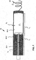
- FIG. 7 is a schematic representation of an example of a functional conductor of an electrode line.
- the embodiment can also be through the equivalent circuit of the FIG. 3 represent. Therefore, in FIG. 7 largely identical reference numerals as in FIG. 3 used.
- the functional conductor 26 has a first longitudinal section L1, not shown here in full length, in which its inner conductor is designed as a hollow helix 26.1 and forms a line resistance Z 0 .
- first longitudinal section L1 comparatively very short second longitudinal section L2 of the functional guide 26 of the inner conductor is formed as a cylindrical conductor 26.2, for example, 2 millimeters in diameter and 10 millimeters in length, with an insulating layer, an inner dielectric (eg, a paint layer) of a thickness d2 of 10 Micrometer is surrounded.
- the hollow helix 26.1 has a significantly higher line resistance for electromagnetic radio frequency waves, as can be seen from the above in connection with FIGS FIGS. 4 to 6 results in calculations and measurements.
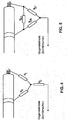
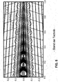
- FIG. 8 is a graph showing the result of a simulation calculation representing the electric field strength and magnetic flux tube magnetic field lines around a longitudinal section of 0 to 1 meter of a prior art elongated electric conductor, which is the equivalent circuit of FIG FIG. 2 corresponds and has an inner electrolyte diameter d iel of 2mm ..
- the thin lines are the field lines or flow tubes. They show the course of the field which forms around the cylindrical line extending on the abscissa of the diagram when a high frequency wave propagates in the plane of the drawing from left to right along the line.
- the ordinate plots the distance from the abscissa in meters between -0.25 and 0.25 meters. Negative distance values are to be understood as the distance in the opposite direction to the direction of positive distance values.
- the bold lines are isolines and encode the electromagnetic energy that is in the respective radius elements 2 ⁇ ⁇ d ⁇ .
- the electromagnetic energy is to be understood as energy averaged over time, so that it is not greatest at the places where the field lines are close together, but generally close to the line.
- the load resistance differs in its size not too much from the internal resistance, so that in this example 61% of the maximum possible active power is implemented.
- the magnetic field lines circling around the line in a cylinder-like manner and are exactly perpendicular to the electric field lines at each point. This is the propagation of a transverse electromagnetic (TEM) wave.
- TEM transverse electromagnetic
- an insulated wire such as an electrode lead in body tissue, is a conduit on which a TEM wave can propagate.
- This line has a characteristic impedance, an attenuation and a wavelength, which are dependent on the frequency.
- the length of one of these onions is half a wavelength. You can read the expected wavelength of 23cm from the diagram.
- FIG. 9 shows for comparison a FIG. 8 corresponding graphical representation of the result of a further simulation calculation, the electric field strength and magnetic field lines or contour lines of magnetic flux tubes around a longitudinal section from 0 to 1 meter of an elongated electrical conductor according to the embodiment of FIG. 7 reproduces.
- an electrode line at the frequency 64MHz also has a strong attenuation.
- the energy at the right-hand part of the diagram, that is to say towards the distal end of the line, is markedly lower than in the case of the electrode line according to the prior art, whose values in FIG Figur8 are shown.
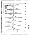
- FIG. 10 shows that over the length of the line occur periodic variations in the ratios of the performance parameters apparent power, reactive power and active power. Over the length of 0 centimeters (proximal end) to 20 centimeters, a damping is visible over 7 periods.
- the length of the inserted line piece is plotted on the abscissa and the respective power ratio on the load resistance of the electrode tip on the ordinate. It can be seen from the initially rising over a length of almost 2 millimeters curves of the active power and the Scheinleitsung that the short line piece to reduce the power parameters should be longer than 2 millimeters. Because up to a length of about 0.5 millimeters, the ratio of the active power with the additional line piece to the active power without the additional line piece at the electrode tip even increases because of the transformation properties. With a 1 cm long line piece, the power in the electrode tip is already reduced to about half.
Claims (10)
- Appareil médical (10) implantable de manière temporaire ou permanente avec au moins un conducteur fonctionnel (26) électrique allongé, qui est isolé du matériau environnant par un diélectrique avec le diamètre intérieur diel,- qui présente un pôle d'électrode (22, 24) pour la délivrance de signaux thérapeutiques ou pour la détection de signaux de diagnostic, lequel représente une résistance de charge ZL pour des ondes électromagnétiques à l'état implanté,- qui présente, entre son extrémité proximale et le pôle d'électrode (22, 24), au moins un premier segment longitudinal (L1) d'une première impédance de ligne Z0 pour des ondes électromagnétiques, et- qui présente, immédiatement adjacent au premier segment longitudinal (L1), au moins un deuxième segment (L2) longitudinal, plus court comparativement au premier segment longitudinal d'une deuxième impédance de ligne Z1 pour les ondes électromagnétiques, long d'au moins 0,25 fois le diamètre intérieur (diel), où la deuxième impédance de ligne est supérieure ou inférieure à la première impédance de ligne et supérieure ou inférieure à la résistance de charge,le conducteur fonctionnel (126) présente un conducteur interne et un conducteur externe en cylindre creux, où le conducteur interne dans le deuxième segment longitudinal (L2) a une forme géométrique dérivant de celle du conducteur interne dans le premier segment longitudinal (L1),
caractérisé en ce que
le conducteur interne est de forme hélicoïdale creuse dans le premier segment longitudinal (L1) et de forme cylindrique dans le deuxième segment longitudinal (L2), et
que le deuxième segment longitudinal (L2) en forme de cylindre du conducteur interne présente un diamètre plus grand que l'hélice creuse du conducteur interne dans le premier segment longitudinal (L1). - Appareil médical selon l'une des revendications précédentes, chez lequel la partie réelle de la deuxième impédance de ligne pour des fréquences radio électromagnétiques est inférieure d'un facteur d'au moins 2 par rapport à la partie réelle de la première impédance de ligne.
- Appareil médical selon l'une des revendications précédentes, chez lequel, dans le conducteur fonctionnel (26, 26'), en direction de l'extrémité distale, un autre premier segment longitudinal (L1) de la première impédance de ligne Z0 se raccorde sur le deuxième segment longitudinal (L2).
- Appareil médical selon l'une des revendications précédentes, chez lequel le deuxième segment longitudinal (L2) est plus long que 2 millimètres.
- Appareil médical selon l'une des revendications précédentes, chez lequel le deuxième segment longitudinal (L2) est plus court que 20 millimètres.
- Appareil médical selon l'une des revendications précédentes, chez lequel le deuxième segment longitudinal (L2) a au maximum une longueur de 10 millimètres.
- Appareil médical selon l'une des revendications précédentes, chez lequel le conducteur interne dans le premier segment longitudinal (L1) du conducteur électrique (20) est en forme d'hélice creuse et est de forme cylindrique dans le deuxième segment longitudinal (L2).
- Appareil médical selon la revendication 7, chez lequel le conducteur interne de forme cylindrique dans le deuxième segment longitudinal (L2) est isolé du conducteur externe par un diélectrique d'une épaisseur d'au moins 5 micromètres.
- Appareil médical selon l'une des revendications précédentes, chez lequel le pôle d'électrode présente une pointe d'électrode (22) à l'extrémité distale du conducteur électrique (20).
- Appareil médical selon la revendication 8, chez lequel la pointe d'électrode (22) se raccorde immédiatement sur le deuxième segment longitudinal (L2).
Applications Claiming Priority (1)
| Application Number | Priority Date | Filing Date | Title |
|---|---|---|---|
| US201061424075P | 2010-12-17 | 2010-12-17 |
Publications (3)
| Publication Number | Publication Date |
|---|---|
| EP2465571A2 EP2465571A2 (fr) | 2012-06-20 |
| EP2465571A3 EP2465571A3 (fr) | 2012-07-04 |
| EP2465571B1 true EP2465571B1 (fr) | 2017-01-18 |
Family
ID=45217372
Family Applications (1)
| Application Number | Title | Priority Date | Filing Date |
|---|---|---|---|
| EP11191741.5A Not-in-force EP2465571B1 (fr) | 2010-12-17 | 2011-12-02 | Appareil implantable |
Country Status (2)
| Country | Link |
|---|---|
| US (1) | US8942826B2 (fr) |
| EP (1) | EP2465571B1 (fr) |
Family Cites Families (5)
| Publication number | Priority date | Publication date | Assignee | Title |
|---|---|---|---|---|
| US6606513B2 (en) * | 2000-02-01 | 2003-08-12 | Surgi-Vision, Inc. | Magnetic resonance imaging transseptal needle antenna |
| CA2623453C (fr) * | 2005-10-21 | 2016-02-09 | Surgi-Vision, Inc. | Systemes de derivation a impedance elevee compatibles avec des systemes irm et procedes associes |
| US8386057B2 (en) | 2006-11-17 | 2013-02-26 | Biotronik Crm Patent Ag | Electrode catheter for interventional use |
| US8275464B2 (en) | 2007-12-06 | 2012-09-25 | Cardiac Pacemakers, Inc. | Leads with high surface resistance |
| WO2010044019A1 (fr) | 2008-10-15 | 2010-04-22 | Koninklijke Philips Electronics N.V. | Sonde pour dispositif médical implantable |
-
2011
- 2011-11-21 US US13/301,675 patent/US8942826B2/en not_active Expired - Fee Related
- 2011-12-02 EP EP11191741.5A patent/EP2465571B1/fr not_active Not-in-force
Non-Patent Citations (1)
| Title |
|---|
| None * |
Also Published As
| Publication number | Publication date |
|---|---|
| EP2465571A3 (fr) | 2012-07-04 |
| US8942826B2 (en) | 2015-01-27 |
| EP2465571A2 (fr) | 2012-06-20 |
| US20120157812A1 (en) | 2012-06-21 |
Similar Documents
| Publication | Publication Date | Title |
|---|---|---|
| EP1923094B1 (fr) | Cathéter à électrode destiné à des interventions | |
| EP1923095B1 (fr) | Electrode destinée à des interventions | |
| US8712544B2 (en) | Electromagnetic shield for a passive electronic component in an active medical device implantable lead | |
| EP2359898A2 (fr) | Élément implantable avec des moyens pour réduire une densité de flux | |
| EP2465572B1 (fr) | Fil implantable compatible avec l'IRM | |
| US9031670B2 (en) | Electromagnetic shield for a passive electronic component in an active medical device implantable lead | |
| EP2110154B1 (fr) | Dispositif de réduction de l'occurrence de pannes pour implants allongés | |
| EP2468353B1 (fr) | Appareil implantable | |
| EP2578268B1 (fr) | Capteur de température pour un appareil médical implantable | |
| EP2465571B1 (fr) | Appareil implantable | |
| EP2465569B1 (fr) | Appareil implantable | |
| EP2446922B1 (fr) | Conducteurs implantables avec des conducteurs supplémentaires pour le découplage de champs | |
| EP2478932B1 (fr) | Appareil implantable | |
| EP2110156B1 (fr) | Elément de découplage de champs à utiliser avec une sonde implantable et appareil médical implantable | |
| EP2478933A2 (fr) | Appareil implantable | |
| EP2465573B1 (fr) | Appareil implantable | |
| EP2985054B1 (fr) | Appareil implantable doté d'un filtre électrique | |
| EP3025756B1 (fr) | Prolongement d'electrodes integre dans un implant actif | |
| EP2848282B1 (fr) | Appareil implantable | |
| DE102020100121A1 (de) | Implantierbare Elektrode mit einer Stichleitung | |
| EP2505229A2 (fr) | Appareil implantable | |
| EP2465570B1 (fr) | Appareil implantable | |
| EP2853288B1 (fr) | Appareil implantable et procédé de fabrication d'un appareil implantable | |
| EP2468356B1 (fr) | Appareil implantable | |
| DE102007022333A1 (de) | Elektrode zu Interventionszwecken |
Legal Events
| Date | Code | Title | Description |
|---|---|---|---|
| PUAL | Search report despatched |
Free format text: ORIGINAL CODE: 0009013 |
|
| PUAI | Public reference made under article 153(3) epc to a published international application that has entered the european phase |
Free format text: ORIGINAL CODE: 0009012 |
|
| AK | Designated contracting states |
Kind code of ref document: A2 Designated state(s): AL AT BE BG CH CY CZ DE DK EE ES FI FR GB GR HR HU IE IS IT LI LT LU LV MC MK MT NL NO PL PT RO RS SE SI SK SM TR |
|
| AX | Request for extension of the european patent |
Extension state: BA ME |
|
| AK | Designated contracting states |
Kind code of ref document: A3 Designated state(s): AL AT BE BG CH CY CZ DE DK EE ES FI FR GB GR HR HU IE IS IT LI LT LU LV MC MK MT NL NO PL PT RO RS SE SI SK SM TR |
|
| AX | Request for extension of the european patent |
Extension state: BA ME |
|
| RIC1 | Information provided on ipc code assigned before grant |
Ipc: A61N 1/05 20060101AFI20120529BHEP |
|
| 17P | Request for examination filed |
Effective date: 20121212 |
|
| RIC1 | Information provided on ipc code assigned before grant |
Ipc: A61N 1/08 20060101ALN20131217BHEP Ipc: A61N 1/05 20060101AFI20131217BHEP |
|
| 17Q | First examination report despatched |
Effective date: 20140218 |
|
| RIC1 | Information provided on ipc code assigned before grant |
Ipc: A61N 1/08 20060101ALN20160331BHEP Ipc: A61N 1/05 20060101AFI20160331BHEP |
|
| RIC1 | Information provided on ipc code assigned before grant |
Ipc: A61N 1/08 20060101ALN20160428BHEP Ipc: A61N 1/05 20060101AFI20160428BHEP |
|
| RIC1 | Information provided on ipc code assigned before grant |
Ipc: A61N 1/08 20060101ALN20160512BHEP Ipc: A61N 1/05 20060101AFI20160512BHEP |
|
| GRAP | Despatch of communication of intention to grant a patent |
Free format text: ORIGINAL CODE: EPIDOSNIGR1 |
|
| INTG | Intention to grant announced |
Effective date: 20160617 |
|
| GRAS | Grant fee paid |
Free format text: ORIGINAL CODE: EPIDOSNIGR3 |
|
| GRAJ | Information related to disapproval of communication of intention to grant by the applicant or resumption of examination proceedings by the epo deleted |
Free format text: ORIGINAL CODE: EPIDOSDIGR1 |
|
| GRAL | Information related to payment of fee for publishing/printing deleted |
Free format text: ORIGINAL CODE: EPIDOSDIGR3 |
|
| GRAR | Information related to intention to grant a patent recorded |
Free format text: ORIGINAL CODE: EPIDOSNIGR71 |
|
| INTC | Intention to grant announced (deleted) | ||
| RIC1 | Information provided on ipc code assigned before grant |
Ipc: A61N 1/05 20060101AFI20161021BHEP Ipc: A61N 1/08 20060101ALN20161021BHEP |
|
| GRAA | (expected) grant |
Free format text: ORIGINAL CODE: 0009210 |
|
| INTG | Intention to grant announced |
Effective date: 20161116 |
|
| AK | Designated contracting states |
Kind code of ref document: B1 Designated state(s): AL AT BE BG CH CY CZ DE DK EE ES FI FR GB GR HR HU IE IS IT LI LT LU LV MC MK MT NL NO PL PT RO RS SE SI SK SM TR |
|
| REG | Reference to a national code |
Ref country code: GB Ref legal event code: FG4D Free format text: NOT ENGLISH |
|
| REG | Reference to a national code |
Ref country code: CH Ref legal event code: EP |
|
| REG | Reference to a national code |
Ref country code: AT Ref legal event code: REF Ref document number: 862547 Country of ref document: AT Kind code of ref document: T Effective date: 20170215 |
|
| REG | Reference to a national code |
Ref country code: IE Ref legal event code: FG4D Free format text: LANGUAGE OF EP DOCUMENT: GERMAN |
|
| REG | Reference to a national code |
Ref country code: DE Ref legal event code: R096 Ref document number: 502011011541 Country of ref document: DE |
|
| REG | Reference to a national code |
Ref country code: NL Ref legal event code: MP Effective date: 20170118 |
|
| REG | Reference to a national code |
Ref country code: LT Ref legal event code: MG4D |
|
| PG25 | Lapsed in a contracting state [announced via postgrant information from national office to epo] |
Ref country code: NL Free format text: LAPSE BECAUSE OF FAILURE TO SUBMIT A TRANSLATION OF THE DESCRIPTION OR TO PAY THE FEE WITHIN THE PRESCRIBED TIME-LIMIT Effective date: 20170118 |
|
| PG25 | Lapsed in a contracting state [announced via postgrant information from national office to epo] |
Ref country code: NO Free format text: LAPSE BECAUSE OF FAILURE TO SUBMIT A TRANSLATION OF THE DESCRIPTION OR TO PAY THE FEE WITHIN THE PRESCRIBED TIME-LIMIT Effective date: 20170418 Ref country code: FI Free format text: LAPSE BECAUSE OF FAILURE TO SUBMIT A TRANSLATION OF THE DESCRIPTION OR TO PAY THE FEE WITHIN THE PRESCRIBED TIME-LIMIT Effective date: 20170118 Ref country code: LT Free format text: LAPSE BECAUSE OF FAILURE TO SUBMIT A TRANSLATION OF THE DESCRIPTION OR TO PAY THE FEE WITHIN THE PRESCRIBED TIME-LIMIT Effective date: 20170118 Ref country code: HR Free format text: LAPSE BECAUSE OF FAILURE TO SUBMIT A TRANSLATION OF THE DESCRIPTION OR TO PAY THE FEE WITHIN THE PRESCRIBED TIME-LIMIT Effective date: 20170118 Ref country code: GR Free format text: LAPSE BECAUSE OF FAILURE TO SUBMIT A TRANSLATION OF THE DESCRIPTION OR TO PAY THE FEE WITHIN THE PRESCRIBED TIME-LIMIT Effective date: 20170419 Ref country code: IS Free format text: LAPSE BECAUSE OF FAILURE TO SUBMIT A TRANSLATION OF THE DESCRIPTION OR TO PAY THE FEE WITHIN THE PRESCRIBED TIME-LIMIT Effective date: 20170518 |
|
| PG25 | Lapsed in a contracting state [announced via postgrant information from national office to epo] |
Ref country code: PL Free format text: LAPSE BECAUSE OF FAILURE TO SUBMIT A TRANSLATION OF THE DESCRIPTION OR TO PAY THE FEE WITHIN THE PRESCRIBED TIME-LIMIT Effective date: 20170118 Ref country code: SE Free format text: LAPSE BECAUSE OF FAILURE TO SUBMIT A TRANSLATION OF THE DESCRIPTION OR TO PAY THE FEE WITHIN THE PRESCRIBED TIME-LIMIT Effective date: 20170118 Ref country code: ES Free format text: LAPSE BECAUSE OF FAILURE TO SUBMIT A TRANSLATION OF THE DESCRIPTION OR TO PAY THE FEE WITHIN THE PRESCRIBED TIME-LIMIT Effective date: 20170118 Ref country code: PT Free format text: LAPSE BECAUSE OF FAILURE TO SUBMIT A TRANSLATION OF THE DESCRIPTION OR TO PAY THE FEE WITHIN THE PRESCRIBED TIME-LIMIT Effective date: 20170518 Ref country code: RS Free format text: LAPSE BECAUSE OF FAILURE TO SUBMIT A TRANSLATION OF THE DESCRIPTION OR TO PAY THE FEE WITHIN THE PRESCRIBED TIME-LIMIT Effective date: 20170118 Ref country code: BG Free format text: LAPSE BECAUSE OF FAILURE TO SUBMIT A TRANSLATION OF THE DESCRIPTION OR TO PAY THE FEE WITHIN THE PRESCRIBED TIME-LIMIT Effective date: 20170418 Ref country code: LV Free format text: LAPSE BECAUSE OF FAILURE TO SUBMIT A TRANSLATION OF THE DESCRIPTION OR TO PAY THE FEE WITHIN THE PRESCRIBED TIME-LIMIT Effective date: 20170118 |
|
| REG | Reference to a national code |
Ref country code: DE Ref legal event code: R097 Ref document number: 502011011541 Country of ref document: DE |
|
| PG25 | Lapsed in a contracting state [announced via postgrant information from national office to epo] |
Ref country code: EE Free format text: LAPSE BECAUSE OF FAILURE TO SUBMIT A TRANSLATION OF THE DESCRIPTION OR TO PAY THE FEE WITHIN THE PRESCRIBED TIME-LIMIT Effective date: 20170118 Ref country code: CZ Free format text: LAPSE BECAUSE OF FAILURE TO SUBMIT A TRANSLATION OF THE DESCRIPTION OR TO PAY THE FEE WITHIN THE PRESCRIBED TIME-LIMIT Effective date: 20170118 Ref country code: SK Free format text: LAPSE BECAUSE OF FAILURE TO SUBMIT A TRANSLATION OF THE DESCRIPTION OR TO PAY THE FEE WITHIN THE PRESCRIBED TIME-LIMIT Effective date: 20170118 Ref country code: IT Free format text: LAPSE BECAUSE OF FAILURE TO SUBMIT A TRANSLATION OF THE DESCRIPTION OR TO PAY THE FEE WITHIN THE PRESCRIBED TIME-LIMIT Effective date: 20170118 Ref country code: RO Free format text: LAPSE BECAUSE OF FAILURE TO SUBMIT A TRANSLATION OF THE DESCRIPTION OR TO PAY THE FEE WITHIN THE PRESCRIBED TIME-LIMIT Effective date: 20170118 |
|
| PLBE | No opposition filed within time limit |
Free format text: ORIGINAL CODE: 0009261 |
|
| STAA | Information on the status of an ep patent application or granted ep patent |
Free format text: STATUS: NO OPPOSITION FILED WITHIN TIME LIMIT |
|
| PG25 | Lapsed in a contracting state [announced via postgrant information from national office to epo] |
Ref country code: SM Free format text: LAPSE BECAUSE OF FAILURE TO SUBMIT A TRANSLATION OF THE DESCRIPTION OR TO PAY THE FEE WITHIN THE PRESCRIBED TIME-LIMIT Effective date: 20170118 Ref country code: DK Free format text: LAPSE BECAUSE OF FAILURE TO SUBMIT A TRANSLATION OF THE DESCRIPTION OR TO PAY THE FEE WITHIN THE PRESCRIBED TIME-LIMIT Effective date: 20170118 |
|
| 26N | No opposition filed |
Effective date: 20171019 |
|
| PG25 | Lapsed in a contracting state [announced via postgrant information from national office to epo] |
Ref country code: SI Free format text: LAPSE BECAUSE OF FAILURE TO SUBMIT A TRANSLATION OF THE DESCRIPTION OR TO PAY THE FEE WITHIN THE PRESCRIBED TIME-LIMIT Effective date: 20170118 |
|
| GBPC | Gb: european patent ceased through non-payment of renewal fee |
Effective date: 20171202 |
|
| PG25 | Lapsed in a contracting state [announced via postgrant information from national office to epo] |
Ref country code: MT Free format text: LAPSE BECAUSE OF FAILURE TO SUBMIT A TRANSLATION OF THE DESCRIPTION OR TO PAY THE FEE WITHIN THE PRESCRIBED TIME-LIMIT Effective date: 20170118 Ref country code: LU Free format text: LAPSE BECAUSE OF NON-PAYMENT OF DUE FEES Effective date: 20171202 |
|
| REG | Reference to a national code |
Ref country code: FR Ref legal event code: ST Effective date: 20180831 |
|
| REG | Reference to a national code |
Ref country code: BE Ref legal event code: MM Effective date: 20171231 |
|
| PG25 | Lapsed in a contracting state [announced via postgrant information from national office to epo] |
Ref country code: FR Free format text: LAPSE BECAUSE OF NON-PAYMENT OF DUE FEES Effective date: 20180102 |
|
| PG25 | Lapsed in a contracting state [announced via postgrant information from national office to epo] |
Ref country code: GB Free format text: LAPSE BECAUSE OF NON-PAYMENT OF DUE FEES Effective date: 20171202 Ref country code: BE Free format text: LAPSE BECAUSE OF NON-PAYMENT OF DUE FEES Effective date: 20171231 |
|
| REG | Reference to a national code |
Ref country code: AT Ref legal event code: MM01 Ref document number: 862547 Country of ref document: AT Kind code of ref document: T Effective date: 20171202 |
|
| PG25 | Lapsed in a contracting state [announced via postgrant information from national office to epo] |
Ref country code: AT Free format text: LAPSE BECAUSE OF NON-PAYMENT OF DUE FEES Effective date: 20171202 |
|
| PG25 | Lapsed in a contracting state [announced via postgrant information from national office to epo] |
Ref country code: HU Free format text: LAPSE BECAUSE OF FAILURE TO SUBMIT A TRANSLATION OF THE DESCRIPTION OR TO PAY THE FEE WITHIN THE PRESCRIBED TIME-LIMIT; INVALID AB INITIO Effective date: 20111202 Ref country code: MC Free format text: LAPSE BECAUSE OF FAILURE TO SUBMIT A TRANSLATION OF THE DESCRIPTION OR TO PAY THE FEE WITHIN THE PRESCRIBED TIME-LIMIT Effective date: 20170118 |
|
| PG25 | Lapsed in a contracting state [announced via postgrant information from national office to epo] |
Ref country code: CY Free format text: LAPSE BECAUSE OF NON-PAYMENT OF DUE FEES Effective date: 20170118 |
|
| PG25 | Lapsed in a contracting state [announced via postgrant information from national office to epo] |
Ref country code: MK Free format text: LAPSE BECAUSE OF FAILURE TO SUBMIT A TRANSLATION OF THE DESCRIPTION OR TO PAY THE FEE WITHIN THE PRESCRIBED TIME-LIMIT Effective date: 20170118 |
|
| PG25 | Lapsed in a contracting state [announced via postgrant information from national office to epo] |
Ref country code: TR Free format text: LAPSE BECAUSE OF FAILURE TO SUBMIT A TRANSLATION OF THE DESCRIPTION OR TO PAY THE FEE WITHIN THE PRESCRIBED TIME-LIMIT Effective date: 20170118 |
|
| PG25 | Lapsed in a contracting state [announced via postgrant information from national office to epo] |
Ref country code: AL Free format text: LAPSE BECAUSE OF FAILURE TO SUBMIT A TRANSLATION OF THE DESCRIPTION OR TO PAY THE FEE WITHIN THE PRESCRIBED TIME-LIMIT Effective date: 20170118 |
|
| PGFP | Annual fee paid to national office [announced via postgrant information from national office to epo] |
Ref country code: IE Payment date: 20211220 Year of fee payment: 11 |
|
| PGFP | Annual fee paid to national office [announced via postgrant information from national office to epo] |
Ref country code: CH Payment date: 20211222 Year of fee payment: 11 |
|
| PGFP | Annual fee paid to national office [announced via postgrant information from national office to epo] |
Ref country code: DE Payment date: 20211222 Year of fee payment: 11 |
|
| REG | Reference to a national code |
Ref country code: DE Ref legal event code: R119 Ref document number: 502011011541 Country of ref document: DE |
|
| REG | Reference to a national code |
Ref country code: CH Ref legal event code: PL |
|
| PG25 | Lapsed in a contracting state [announced via postgrant information from national office to epo] |
Ref country code: LI Free format text: LAPSE BECAUSE OF NON-PAYMENT OF DUE FEES Effective date: 20221231 Ref country code: IE Free format text: LAPSE BECAUSE OF NON-PAYMENT OF DUE FEES Effective date: 20221202 Ref country code: DE Free format text: LAPSE BECAUSE OF NON-PAYMENT OF DUE FEES Effective date: 20230701 Ref country code: CH Free format text: LAPSE BECAUSE OF NON-PAYMENT OF DUE FEES Effective date: 20221231 |