EP2468356B1 - Appareil implantable - Google Patents
Appareil implantable Download PDFInfo
- Publication number
- EP2468356B1 EP2468356B1 EP11192954.3A EP11192954A EP2468356B1 EP 2468356 B1 EP2468356 B1 EP 2468356B1 EP 11192954 A EP11192954 A EP 11192954A EP 2468356 B1 EP2468356 B1 EP 2468356B1
- Authority
- EP
- European Patent Office
- Prior art keywords
- medical device
- electrode
- function
- conductors
- electrical
- Prior art date
- Legal status (The legal status is an assumption and is not a legal conclusion. Google has not performed a legal analysis and makes no representation as to the accuracy of the status listed.)
- Not-in-force
Links
- 239000004020 conductor Substances 0.000 claims description 56
- 230000000694 effects Effects 0.000 claims description 14
- 238000010438 heat treatment Methods 0.000 claims description 11
- 238000013016 damping Methods 0.000 claims description 6
- 230000005672 electromagnetic field Effects 0.000 claims description 5
- 230000005540 biological transmission Effects 0.000 claims description 2
- 239000003990 capacitor Substances 0.000 claims description 2
- 230000000704 physical effect Effects 0.000 claims description 2
- 238000002560 therapeutic procedure Methods 0.000 claims description 2
- 210000001519 tissue Anatomy 0.000 description 10
- 239000007943 implant Substances 0.000 description 9
- 230000000747 cardiac effect Effects 0.000 description 8
- 230000000638 stimulation Effects 0.000 description 7
- 238000001514 detection method Methods 0.000 description 6
- 210000005003 heart tissue Anatomy 0.000 description 3
- 210000005241 right ventricle Anatomy 0.000 description 3
- 230000002861 ventricular Effects 0.000 description 3
- 239000011159 matrix material Substances 0.000 description 2
- 210000004165 myocardium Anatomy 0.000 description 2
- 230000004044 response Effects 0.000 description 2
- 238000002679 ablation Methods 0.000 description 1
- 230000008878 coupling Effects 0.000 description 1
- 238000010168 coupling process Methods 0.000 description 1
- 238000005859 coupling reaction Methods 0.000 description 1
- 230000001934 delay Effects 0.000 description 1
- 230000001066 destructive effect Effects 0.000 description 1
- 230000009977 dual effect Effects 0.000 description 1
- 230000005684 electric field Effects 0.000 description 1
- 238000011156 evaluation Methods 0.000 description 1
- 230000003203 everyday effect Effects 0.000 description 1
- 230000000004 hemodynamic effect Effects 0.000 description 1
- 230000003993 interaction Effects 0.000 description 1
- 210000005240 left ventricle Anatomy 0.000 description 1
- 239000000463 material Substances 0.000 description 1
- 239000002184 metal Substances 0.000 description 1
- 230000003287 optical effect Effects 0.000 description 1
- 238000005457 optimization Methods 0.000 description 1
- 230000010363 phase shift Effects 0.000 description 1
- 210000005245 right atrium Anatomy 0.000 description 1
- 230000001953 sensory effect Effects 0.000 description 1
- 230000001225 therapeutic effect Effects 0.000 description 1
- 238000010792 warming Methods 0.000 description 1
Images


Classifications
-
- A—HUMAN NECESSITIES
- A61—MEDICAL OR VETERINARY SCIENCE; HYGIENE
- A61N—ELECTROTHERAPY; MAGNETOTHERAPY; RADIATION THERAPY; ULTRASOUND THERAPY
- A61N1/00—Electrotherapy; Circuits therefor
- A61N1/18—Applying electric currents by contact electrodes
- A61N1/32—Applying electric currents by contact electrodes alternating or intermittent currents
- A61N1/36—Applying electric currents by contact electrodes alternating or intermittent currents for stimulation
- A61N1/362—Heart stimulators
- A61N1/37—Monitoring; Protecting
- A61N1/3718—Monitoring of or protection against external electromagnetic fields or currents
-
- A—HUMAN NECESSITIES
- A61—MEDICAL OR VETERINARY SCIENCE; HYGIENE
- A61B—DIAGNOSIS; SURGERY; IDENTIFICATION
- A61B18/00—Surgical instruments, devices or methods for transferring non-mechanical forms of energy to or from the body
- A61B18/04—Surgical instruments, devices or methods for transferring non-mechanical forms of energy to or from the body by heating
- A61B18/12—Surgical instruments, devices or methods for transferring non-mechanical forms of energy to or from the body by heating by passing a current through the tissue to be heated, e.g. high-frequency current
- A61B18/14—Probes or electrodes therefor
- A61B18/1492—Probes or electrodes therefor having a flexible, catheter-like structure, e.g. for heart ablation
-
- A—HUMAN NECESSITIES
- A61—MEDICAL OR VETERINARY SCIENCE; HYGIENE
- A61N—ELECTROTHERAPY; MAGNETOTHERAPY; RADIATION THERAPY; ULTRASOUND THERAPY
- A61N1/00—Electrotherapy; Circuits therefor
- A61N1/02—Details
- A61N1/04—Electrodes
- A61N1/05—Electrodes for implantation or insertion into the body, e.g. heart electrode
- A61N1/056—Transvascular endocardial electrode systems
-
- A—HUMAN NECESSITIES
- A61—MEDICAL OR VETERINARY SCIENCE; HYGIENE
- A61N—ELECTROTHERAPY; MAGNETOTHERAPY; RADIATION THERAPY; ULTRASOUND THERAPY
- A61N1/00—Electrotherapy; Circuits therefor
- A61N1/02—Details
- A61N1/08—Arrangements or circuits for monitoring, protecting, controlling or indicating
- A61N1/086—Magnetic resonance imaging [MRI] compatible leads
Definitions
- the invention relates to a permanently or temporarily implantable device with an elongated electrical conductor.
- Such devices such as electrode lines for electrostimulation, have the disadvantage that their electrical conductor can heat up in a magnetic resonance tomograph, because the magnetic fields prevailing in the magnetic resonance tomographs induce not inconsiderable electrical currents in the electrical conductor. Also, such induced currents can be delivered via electrode poles of the electrode line to surrounding tissue and thus, for example, lead to undesired tissue warming. Therefore, cardiac pacemaker patients today can usually not be examined or only to a limited extent in a magnetic resonance tomograph.
- At least one stimulation electrode lead which has a standardized electrical connection at its proximal end provided for connection to the pacemaker or defibrillator, is typically connected to implantable cardiac pacemakers or defibrillators (also collectively referred to as cardiac stimulators or implantable pulse generators) has one or more electrode poles at its distal end provided for placement in the heart.
- implantable cardiac pacemakers or defibrillators also collectively referred to as cardiac stimulators or implantable pulse generators
- Such an electrode pole serves to deliver electrical impulses to the tissue (myocardium) of the heart or to sense electric fields in order to be able to sense an activity of a heart within the scope of so-called sensing.
- electrode poles typically form electrically conductive surface portions of an electrode lead.
- Electrode poles are typically provided as a ring electrode in the form of a ring around the electrode lead or in the form of a tip or tip electrode at the distal end of the electrode lead.
- the electrode poles are via one or more electrical Conductor electrically connected to contacts of the electrical connection of the electrode line at its proximal end.
- the electrode leads extend at their proximal end and the electrode poles at the distal end of the electrode lead one or more electrical conductors electrically connecting one or more of the electrode poles to one or more of the contacts.
- These electrical conductors can be used, on the one hand, to transmit stimulation pulses to the electrode poles and, on the other hand, to transmit electrical signals picked up by the electrode poles to the proximal end of the electrode lead and are also referred to as function leads in the course of the further description.
- function lines are required for the functions of the respective electrode line electrical conductors and as such the risk that in them by external alternating magnetic fields electrical currents are induced, which can lead, for example, to an undesirable heating of the function lines or connected to her electrode poles or the delivery corresponding currents can lead to the surrounding tissue via the electrode poles and thus to a heating of the surrounding tissue.
- the PCT application WO2008073445A2 describes an electrode lead suitable for use in an MRI scanner.
- the invention has for its object to provide a device which solves the problem described above.
- this object is achieved by a temporary or permanently implantable medical device, which is connected or connectable to at least two elongate electrical function conductors for the transmission of therapy signals or diagnostic signals or both, and at least one connected to at least one of the functional conductor Elektrodenpol, via the electrical Power can be delivered to surrounding body tissue in the case of use or can be sensed with the electrical potential in tissue surrounding in the case of use, or both.
- the medical device has a wave transfer module which is connected or to be connected to the functional conductor and which is designed to transform waves arriving via a functional conductor and to turn them on as a transformed wave to another functional conductor or the same functional conductor in such a controlled manner that the waves Overlap destructively at the electrode pole.
- a medical device for which the invention is particularly relevant is an electrode lead e.g. for a heart stimulator, in which the functional conductors are electrical conductors of the electrode line, wherein the electrode line has electrode poles, which are electrically connected to the wave transfer module via the functional conductors.
- the medical device for example an implantable heart stimulator connected to an electrode line, may have a housing which is electrically conductive or has an electrode pole via which electric current can be delivered to surrounding body tissue or sensed with the electrical potential in surrounding tissue both.
- the medical device comprises an interference field recognition device which is designed to detect the presence of strong electromagnetic fields and to generate a corresponding output signal if present, and which is connected to a control unit for controlling the shaft transfer module.
- an interference field recognition device which is designed to detect the presence of strong electromagnetic fields and to generate a corresponding output signal if present, and which is connected to a control unit for controlling the shaft transfer module.
- the interference field detection device may include a temperature sensor arranged to detect heating of an electrode pole. In this way, the interference field detection device detects a heating as a result of high-frequency interference fields and thus interference fields indirectly about their effect.
- the temperature sensors are located at the electrode poles or other locations that may heat up due to interactions with electromagnetic fields.
- the interference field recognition device can have a sensor for currents or voltages induced in a function conductor and thus be configured to directly detect induced currents or voltages.
- the wave transfer module has a delay line which delays and / or attenuates electromagnetic waves, so that, in the event of operation, a transformed wave is produced, which destructively superimposes itself with an induced wave on the same or another function conductor and compensates for the induced wave in this way.
- the delay line may have an impedance that causes this effect.
- the delay line is realized by one or more, preferably discrete electronic components from a group comprising coils, capacitors, ohmic resistors and transformers (pulse transformer). These form, for example, an LC circuit, possibly also with an ohmic resistance, in order to set the damping.
- the delay line may have spatial structures that have wave-delaying and / or damping effect due to their physical properties.
- Such spatial structures are not necessarily discrete electronic components but e.g. a waveguide, a coax line, a strip line, with possibly lossy materials to adjust the damping.
- the wave transfer module is preferably adjustable in terms of its effect, in particular with regard to its delay effect and / or its damping effect, e.g. by the adjustable elements electrical, mechanical, optical etc are operated.
- the setting of the controllable delay lines can also be done by an external programmer.
- the wave transfer module it makes sense for the wave transfer module to have a switching unit which is arranged and configured to connect transformed waves to a function conductor determined by the switching unit or not. This makes it possible to use the shaft transfer module only if it is necessary and beyond to adapt to the particular application.
- the setting of the switching unit can also be done by an external programmer.
- a delay line of the shaft transfer module connects at least two function conductors, wherein the connection is to be established via the switching unit.
- the switching unit may take the form of a switching matrix in which each cross point in the switching matrix is occupied by a switch.
- the medical device may include a termination impedance unit
- the shaft transfer module may include a switching unit that is arranged and configured to connect a function conductor to a termination impedance unit.
- the termination impedance can cause a phase shift of a wave on a function guide and thus also contribute to the desired effect of wave cancellation.
- at least one impedance value of the terminating impedance unit is electrically, mechanically or optically controllable.
- the terminating impedances can be realized discretely or physically.
- the setting of the controllable terminating impedances can also be done by an external programming device.
- the control unit is preferably designed to control the controllable delay lines and / or the controllable terminating impedances and / or the switching unit as a function of an output signal of the interference field recognition device in such a way that an interference-induced heating at the electrode poles is minimized.
- a battery-powered electronic implant with an electrically conductive housing or housing with at least one Elektrodenpol, electrical function conductors that connect electrode terminals electrical feedthroughs of the implant to conduct electrical signals from the respective Elektrodenpol in the implant can, an interference field detection device for detecting the presence strong electro-magnetic fields, in particular MRI fields, and a Wellentransfermodul which is controlled by the Störfeldkennungsvorraum via a control device and the at least one functional conductor in the implant incoming waves so transformed and alsschaltet on at least one other function guide, that the waves at the distal Elektrodenpolen Destructively superimpose, so that there MRI-related heating is minimized.
- controllable terminating impedance As an alternative to a controllable terminating impedance, it is also possible to provide a controllable generator which is designed to actively feed a compensation signal into a functional conductor.
- the compensation signal to be supplied has the same frequency as the interference signal and a specific phase position wherein the frequency is determined by the Störfeldkennungsö and the phase position and amplitude after evaluation of the temperature signals are adjusted so that the interference field induced heating at the Elektrodenpolen (if necessary, the temperature measuring points ) is minimized.
- the implantable cardiac stimulator 10 may be a pacemaker or a cardioverter / defibrillator (ICD).
- the heart stimulator 10 is a ventricular pacemaker and defibrillator.
- Other known cardiac stimulators are dual chamber pacemakers for stimulation of the right atrium and right ventricle, or biventricular pacemakers, which can also stimulate the left ventricle in addition to the right ventricle.
- Such stimulators typically have a housing 12, which is usually made of metal and thus is electrically conductive and can serve as a large electrode pole.
- a terminal housing 14 is typically attached, which is also referred to as a header.
- Such a header typically Contact sockets for receiving plug contacts.
- the contact sockets have electrical contacts 16, which are connected via corresponding conductors with an arranged in the housing 12 of the heart stimulator 10 electronics.
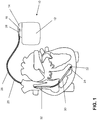
- the electrode line 20 likewise constitutes an implantable medical device.
- electrode poles in the form of a tip or tip electrode 22 and a ring electrode 24 arranged in the vicinity thereof are arranged in a manner known per se.
- the electrode poles 22 and 24 are designed such that, depending on the function of a cardiac stimulator to which the electrode lead 20 is connected, they serve to sense electrical potentials of the heart tissue (myocardium) or to emit electrical signals, for example to deliver stimulation pulses to the surrounding them Heart tissue, are formed.
- FIG. 1 shows how the electrode poles, so the tip electrode 22 and the ring electrode 24, in the application, the electrode line 20, located in the apex of a right ventricle of a heart.
- Both the tip electrode 22 and the ring electrode 24 are electrically connected via at least one electrical conductor 26 to a plug contact 28 at the proximal end of the electrode line 20.
- the plug contact 28 has electrical contacts which correspond to the electrical contacts 16 of the contact socket in the connection housing 14 of the implantable cardiac stimulator.
- the electrical conductors 26 in the electrode line 20 may be formed as approximately elongated cable conductor or as a helical coiled conductor.
- Such conductors electrically conductively connect functional electrode poles to electrical contacts of the plug-in contact at the proximal end of the electrode line 20 are referred to as function conductors in the context of this text, since they transmit, for example, electrical signals from the plug contact to the respective electrode pole, or sensed signals representing electrical potential from the sensor lead respective electrode pole to the plug contact and thus serve the elementary function of the medical device.
- the electrical conductors 26 which connect the electrode poles 22 and 24, respectively, to the electrical contacts of the plug 28 of the electrode line 20 are over most of their Length surrounded by an insulating sheath, so that an electrical contact with the tissue of the heart targeted via the electrode poles comes about.
- the electrode line 20 In addition to the electrode poles 22 and 24, which typically serve the (in this case, ventricular) stimulation of the heart tissue, the electrode line 20 also has two larger-area electrode poles 30 and 32, which serve as defibrillation electrodes and are formed by at least one bare helix-like coiled wire ,
- an ablation electrode lead can in principle also be used, which likewise projects into the heart of a patient in the application and which is controlled by a device arranged outside the patient and is connected to it for this purpose.
- FIG. 2 shows a schematic representation of the internal structure of a medical device according to the invention.
- the medical device has an electrically conductive housing 100, which is made of the housing 12 FIG. 1 equivalent.
- two electrode lines 102 and 104 each having a tip electrode 106 and a ring electrode 108.
- Each of the tip electrodes 106 and the ring electrodes 108 each forms an electrode pole.
- Each electrode pole is connected via a separate supply line 110 to an electronics inside the housing 100.
- the supply lines 110 each form a functional conductor.
- temperature sensors 112 are arranged, which are connected via signal lines 114 to a control unit 116 in the interior of the housing 100.
- thermo sensors 112 instead of the temperature sensors 112, other sensors may be used to detect electromagnetic interference fields or currents or voltages induced in the supply lines 110.
- the leads 110 (function guide) and the signal lines 114 are over in FIG. 2 not shown plug and led through housing bushings 140 into the housing 100.
- the functional conductor 110 is connected to the typical components of a heart stimulator and sensing units or stimulation units. This is in FIG. 2 represented by the block 118, which represents the sensory and therapeutic pacemaker electronics.
- the function conductors 110 are guided on the one hand to the pacemaker electronics 118 and on the other hand to switching units 120 and 122, which are designed as switching matrices.
- a wave transfer module 124 Connected to the switch matrices 120 and 122 is a wave transfer module 124 which has (in the illustrated case three) adjustable delay lines 126.
- the delay lines 126 are adjustable in terms of their delay effect and / or their damping effect.
- they are connected via control lines 128 to the control unit 116. In this way, they may be received by the controller 116 in response to the signals that the controller 116 receives via the signal lines 114 from the sensors 112 in the electrode lines 102 and 104.
- control unit 116 is configured to receive both the switching matrices 120 and 122 and the delay lines 126 in response to the signals received via the signal lines 114 so that the incoming via the signal lines 114 signals indicate no heating of the electrode poles 106 and 108 as possible.
- control unit 116 can also be regarded as a controller.
- the latter effect is achieved by means of the adjustable delay lines 126 by switching incoming waves via the function conductors 110 to the adjustable delay lines 126 and setting the delay lines 126 such that the waves are transformed in one way and onto the same or other functional conductors be switched so that they interfere destructively with induced waves and so cancel the effect of the induced waves.
- this purpose is served by a terminating impedance unit 130, which has three adjustable terminating impedances 132 in the specific case.
- the adjustable impedances 132 may be adjusted by the control unit 116 via control lines 134.
- the adjustable terminating impedances 132 allow the reflection of the waves on the functional conductors 110 at their proximal, defined by the termination units Ends are adjusted in terms of phase and attenuation, in order to achieve in this way also a destructive superposition of waves in the region of the electrode poles of the respective function guide.
- the terminating impedance unit 130 it is also possible to provide a compensation signal generator which actively and by the control unit 116 generates compensation signals and feeds them into the respective functional conductor.
- housing 100 of the heart stimulator is a separate pole, which is also electrically connected (see reference numeral 136) to the switch matrices 120 and 122 and the heart stimulator electronics 118.
- the control unit and thus the behavior of the switching units 120 and 122 and the settings of the delay lines 126 and the terminating impedances 132 are externally programmable. This is indicated by the arrow 300.
- the wiring of the electrode inputs in the implant is automatically reconfigured. This causes the control unit 116, which is programmed or constructed accordingly. This wiring occurs only temporarily while the fault is present, in everyday operation of the implant, the high-resolution and broadband signal recording, in particular the impedance detection for a hemodynamic sensor, not affected. Then the electrode leads run directly (as is conventional) into the electronics 118 of the heart stimulator. In a preferred implementation, during the fault and circuit according to the invention with delay lines, the electronics 118 are switched off at some or all inputs. A dedicated, controlled by the control unit 116 switch is in FIG. 2 not shown.
- an optional additional interference detection unit 150 is shown that generally responds to interference fields and, in this case, activates the control unit 116 for the duration of the interference fields or a predetermined period of time as described above.
- the coupling of the leads by means of the switching matrices 120 and 122 is such that e.g. the inner conductor of a first electrode (coaxial) is connected to the outer conductor of a second electrode.
- the inner conductor of the second electrode is simultaneously switched to the outer conductor of the first electrode (cross-connection).
- the delay is almost 0 seconds, i. It is directly connected without the use of delay lines.
Landscapes
- Health & Medical Sciences (AREA)
- Heart & Thoracic Surgery (AREA)
- Life Sciences & Earth Sciences (AREA)
- Engineering & Computer Science (AREA)
- Animal Behavior & Ethology (AREA)
- Biomedical Technology (AREA)
- Nuclear Medicine, Radiotherapy & Molecular Imaging (AREA)
- Cardiology (AREA)
- General Health & Medical Sciences (AREA)
- Public Health (AREA)
- Veterinary Medicine (AREA)
- Radiology & Medical Imaging (AREA)
- Physics & Mathematics (AREA)
- Surgery (AREA)
- Electromagnetism (AREA)
- Otolaryngology (AREA)
- Plasma & Fusion (AREA)
- Medical Informatics (AREA)
- Molecular Biology (AREA)
- Vascular Medicine (AREA)
- Electrotherapy Devices (AREA)
Claims (10)
- Appareil médical (10) implantable de manière temporaire ou permanente, doté d'au moins deux conducteurs électriques fonctionnels (110) allongés destinés à la transmission de signaux thérapeutiques ou de signaux de diagnostic, ou des deux, ledit appareil étant relié ou devant être relié avec les conducteurs fonctionnels, et doté d'au moins un pôle d'électrode (22, 24, 30, 32) relié avec au moins un conducteur fonctionnel par le biais duquel un courant électrique peut être délivré à un tissu corporel entourant un lieu d'utilisation, ou à l'aide duquel des potentiels électriques peuvent être détectés dans le tissu entourant le lieu d'utilisation, ou les deux, les conducteurs fonctionnels (110) étant des conducteurs électriques d'une ligne d'électrode (20, 102, 104) qui présente des pôles d'électrode, lesquels sont reliés électriquement avec les conducteurs fonctionnels (110),
caractérisé en ce que
l'appareil médical présente un module de transfert d'ondes (124, 220), le module de transfert d'ondes (124, 220) présentant une ligne de délai (126) et le module de transfert d'ondes (124, 220) étant relié ou devant être relié avec les conducteurs fonctionnels (110) et qui est conçu pour transformer des ondes arrivant par le biais d'un conducteur fonctionnel (110) et les brancher sous forme d'ondes transformées sur un autre conducteur fonctionnel (110) de manière à ce que les ondes fassent des interférences destructives au niveau du pôle d'électrode (22, 24, 30, 32). - Appareil médical selon la revendication 1, caractérisé en ce que l'appareil médical (10) possède un boitier (12), lequel est conçu conducteur électriquement ou présente un pôle d'électrode (136) par lequel du courant électrique peut être appliqué sur du tissu corporel entourant le lieu d'utilisation ou avec lequel des potentiels électriques peuvent être délivrés dans le tissu environnant, ou les deux.
- Appareil médical selon la revendication 1 à 2, caractérisé en ce que l'appareil médical (10) présente un dispositif de reconnaissance de champ brouillage (150), qui est conçu pour détecter la présence de champs électromagnétiques élevés et dans le cas de la présence, générer un signal démission correspondant, et qui est relié avec une unité de commande (116) pour la commande du module de transfert d'ondes (124, 220).
- Appareil médical selon la revendication 3, caractérisé en ce que le dispositif de reconnaissance de champs de brouillage (150) présente un capteur de température qui est disposé de telle manière qu'il peut détecter le réchauffement d'un pôle d'électrode (22, 24, 30, 32, 136).
- Appareil médical selon la revendication 3, caractérisé en ce que le dispositif de reconnaissance de champs de brouillage (150) présente un capteur pour des courants ou des tensions induits dans un conducteur fonctionnel (110).
- Appareil médical selon l'une des revendications 1 à 5, caractérisé en ce que la ligne de délai (126) est réalisée par un ou plusieurs composants électroniques d'un groupe qui comprend des bobines, des condensateurs, des résistances ohmiques et des transmetteurs.
- Appareil médical selon l'une des revendications 1 à 5, caractérisé en ce que la ligne de délai (126) présente des structures dans l'espace qui, en raison de leurs propriétés, ont un effet causant un retard des ondes et/ou un effet d'amortissement.
- Appareil médical selon l'une des revendications 1 à 7, caractérisé en ce que le module de transfert d'ondes (124, 220) peut être réglé au niveau de son action.
- Appareil médical selon l'une des revendications 1 à 8, caractérisé en ce que le module de transfert d'ondes (124, 220) présente une unité de commutation (120, 122) qui est disposée et prévue pour couper ou non des ondes transformées sur un conducteur fonctionnel (110) donné par l'unité de commutation (120, 122).
- Appareil médical selon la revendication 3, et l'une des revendications 8 à 9, caractérisé en ce que l'unité de commande (116) est conçue pour commander les lignes de délai (126) pouvant être commandées et/ou l'unité de commutation (120, 122) en fonction d'un signal d'émission du dispositif de reconnaissance de champs de brouillage (150) de telle manière, qu'en fonctionnement, un réchauffement induit par des champs de brouillage est minimisé au niveau des pôles d'électrode (22, 24, 30, 32, 136).
Applications Claiming Priority (1)
| Application Number | Priority Date | Filing Date | Title |
|---|---|---|---|
| US201061425249P | 2010-12-21 | 2010-12-21 |
Publications (2)
| Publication Number | Publication Date |
|---|---|
| EP2468356A1 EP2468356A1 (fr) | 2012-06-27 |
| EP2468356B1 true EP2468356B1 (fr) | 2018-11-21 |
Family
ID=45318958
Family Applications (1)
| Application Number | Title | Priority Date | Filing Date |
|---|---|---|---|
| EP11192954.3A Not-in-force EP2468356B1 (fr) | 2010-12-21 | 2011-12-12 | Appareil implantable |
Country Status (2)
| Country | Link |
|---|---|
| US (1) | US8996136B2 (fr) |
| EP (1) | EP2468356B1 (fr) |
Family Cites Families (3)
| Publication number | Priority date | Publication date | Assignee | Title |
|---|---|---|---|---|
| US20050216075A1 (en) | 2003-04-08 | 2005-09-29 | Xingwu Wang | Materials and devices of enhanced electromagnetic transparency |
| US7765005B2 (en) | 2004-02-12 | 2010-07-27 | Greatbatch Ltd. | Apparatus and process for reducing the susceptability of active implantable medical devices to medical procedures such as magnetic resonance imaging |
| US8768486B2 (en) | 2006-12-11 | 2014-07-01 | Medtronic, Inc. | Medical leads with frequency independent magnetic resonance imaging protection |
-
2011
- 2011-11-21 US US13/301,694 patent/US8996136B2/en not_active Expired - Fee Related
- 2011-12-12 EP EP11192954.3A patent/EP2468356B1/fr not_active Not-in-force
Non-Patent Citations (1)
| Title |
|---|
| None * |
Also Published As
| Publication number | Publication date |
|---|---|
| US8996136B2 (en) | 2015-03-31 |
| EP2468356A1 (fr) | 2012-06-27 |
| US20120157814A1 (en) | 2012-06-21 |
Similar Documents
| Publication | Publication Date | Title |
|---|---|---|
| EP1923094B1 (fr) | Cathéter à électrode destiné à des interventions | |
| DE60310194T2 (de) | Filterung von gekoppelten elektromagnetischen signalen auf zuleitungen | |
| EP2359898A2 (fr) | Élément implantable avec des moyens pour réduire une densité de flux | |
| DE112010001330T5 (de) | MRT-kompatible implantierbare Anschlusselektroden-Schnittstelle | |
| EP2465572B1 (fr) | Fil implantable compatible avec l'IRM | |
| EP2502646B1 (fr) | Appareil implantable | |
| EP2578268B1 (fr) | Capteur de température pour un appareil médical implantable | |
| EP2359895B1 (fr) | Sonde d'adaptation pour l'introduction d'implants médicaux actifs dans des dispositifs d'électrodes implantées et ensemble comprenant un dispositif d'électrodes implantables et une sonde d'adaptation | |
| EP2468353B1 (fr) | Appareil implantable | |
| EP2465569B1 (fr) | Appareil implantable | |
| EP2478932B1 (fr) | Appareil implantable | |
| EP2548609A1 (fr) | Dérivation d'électrode multi-usage unipolaire et installation de stimulation et de défibrillation | |
| EP2468356B1 (fr) | Appareil implantable | |
| EP2446922B1 (fr) | Conducteurs implantables avec des conducteurs supplémentaires pour le découplage de champs | |
| EP2465573B1 (fr) | Appareil implantable | |
| EP2465570B1 (fr) | Appareil implantable | |
| EP2478933A2 (fr) | Appareil implantable | |
| EP2848282B1 (fr) | Appareil implantable | |
| EP2985054B1 (fr) | Appareil implantable doté d'un filtre électrique | |
| EP3025756B1 (fr) | Prolongement d'electrodes integre dans un implant actif | |
| EP2505229A2 (fr) | Appareil implantable | |
| EP3854449A1 (fr) | Appareil médical pouvant être implanté pour stimuler un c ur humain ou animal | |
| EP2915559B1 (fr) | Appareil implantable | |
| EP2848281B1 (fr) | Dispositif d'électrodes pour un implant médical et implant médical doté d'un dispositif d'électrodes | |
| EP2465571A2 (fr) | Appareil implantable |
Legal Events
| Date | Code | Title | Description |
|---|---|---|---|
| AK | Designated contracting states |
Kind code of ref document: A1 Designated state(s): AL AT BE BG CH CY CZ DE DK EE ES FI FR GB GR HR HU IE IS IT LI LT LU LV MC MK MT NL NO PL PT RO RS SE SI SK SM TR |
|
| AX | Request for extension of the european patent |
Extension state: BA ME |
|
| PUAI | Public reference made under article 153(3) epc to a published international application that has entered the european phase |
Free format text: ORIGINAL CODE: 0009012 |
|
| 17P | Request for examination filed |
Effective date: 20121212 |
|
| 17Q | First examination report despatched |
Effective date: 20171123 |
|
| GRAP | Despatch of communication of intention to grant a patent |
Free format text: ORIGINAL CODE: EPIDOSNIGR1 |
|
| RIC1 | Information provided on ipc code assigned before grant |
Ipc: A61N 1/362 20060101ALN20180619BHEP Ipc: A61N 1/37 20060101ALN20180619BHEP Ipc: A61N 1/08 20060101AFI20180619BHEP |
|
| INTG | Intention to grant announced |
Effective date: 20180706 |
|
| GRAS | Grant fee paid |
Free format text: ORIGINAL CODE: EPIDOSNIGR3 |
|
| GRAA | (expected) grant |
Free format text: ORIGINAL CODE: 0009210 |
|
| AK | Designated contracting states |
Kind code of ref document: B1 Designated state(s): AL AT BE BG CH CY CZ DE DK EE ES FI FR GB GR HR HU IE IS IT LI LT LU LV MC MK MT NL NO PL PT RO RS SE SI SK SM TR |
|
| REG | Reference to a national code |
Ref country code: CH Ref legal event code: EP |
|
| REG | Reference to a national code |
Ref country code: IE Ref legal event code: FG4D Free format text: LANGUAGE OF EP DOCUMENT: GERMAN |
|
| REG | Reference to a national code |
Ref country code: AT Ref legal event code: REF Ref document number: 1066850 Country of ref document: AT Kind code of ref document: T Effective date: 20181215 |
|
| REG | Reference to a national code |
Ref country code: DE Ref legal event code: R096 Ref document number: 502011015039 Country of ref document: DE |
|
| REG | Reference to a national code |
Ref country code: NL Ref legal event code: MP Effective date: 20181121 |
|
| PG25 | Lapsed in a contracting state [announced via postgrant information from national office to epo] |
Ref country code: LT Free format text: LAPSE BECAUSE OF FAILURE TO SUBMIT A TRANSLATION OF THE DESCRIPTION OR TO PAY THE FEE WITHIN THE PRESCRIBED TIME-LIMIT Effective date: 20181121 Ref country code: IS Free format text: LAPSE BECAUSE OF FAILURE TO SUBMIT A TRANSLATION OF THE DESCRIPTION OR TO PAY THE FEE WITHIN THE PRESCRIBED TIME-LIMIT Effective date: 20190321 Ref country code: NO Free format text: LAPSE BECAUSE OF FAILURE TO SUBMIT A TRANSLATION OF THE DESCRIPTION OR TO PAY THE FEE WITHIN THE PRESCRIBED TIME-LIMIT Effective date: 20190221 Ref country code: FI Free format text: LAPSE BECAUSE OF FAILURE TO SUBMIT A TRANSLATION OF THE DESCRIPTION OR TO PAY THE FEE WITHIN THE PRESCRIBED TIME-LIMIT Effective date: 20181121 Ref country code: LV Free format text: LAPSE BECAUSE OF FAILURE TO SUBMIT A TRANSLATION OF THE DESCRIPTION OR TO PAY THE FEE WITHIN THE PRESCRIBED TIME-LIMIT Effective date: 20181121 Ref country code: ES Free format text: LAPSE BECAUSE OF FAILURE TO SUBMIT A TRANSLATION OF THE DESCRIPTION OR TO PAY THE FEE WITHIN THE PRESCRIBED TIME-LIMIT Effective date: 20181121 Ref country code: HR Free format text: LAPSE BECAUSE OF FAILURE TO SUBMIT A TRANSLATION OF THE DESCRIPTION OR TO PAY THE FEE WITHIN THE PRESCRIBED TIME-LIMIT Effective date: 20181121 Ref country code: BG Free format text: LAPSE BECAUSE OF FAILURE TO SUBMIT A TRANSLATION OF THE DESCRIPTION OR TO PAY THE FEE WITHIN THE PRESCRIBED TIME-LIMIT Effective date: 20190221 |
|
| PG25 | Lapsed in a contracting state [announced via postgrant information from national office to epo] |
Ref country code: PT Free format text: LAPSE BECAUSE OF FAILURE TO SUBMIT A TRANSLATION OF THE DESCRIPTION OR TO PAY THE FEE WITHIN THE PRESCRIBED TIME-LIMIT Effective date: 20190321 Ref country code: SE Free format text: LAPSE BECAUSE OF FAILURE TO SUBMIT A TRANSLATION OF THE DESCRIPTION OR TO PAY THE FEE WITHIN THE PRESCRIBED TIME-LIMIT Effective date: 20181121 Ref country code: NL Free format text: LAPSE BECAUSE OF FAILURE TO SUBMIT A TRANSLATION OF THE DESCRIPTION OR TO PAY THE FEE WITHIN THE PRESCRIBED TIME-LIMIT Effective date: 20181121 Ref country code: AL Free format text: LAPSE BECAUSE OF FAILURE TO SUBMIT A TRANSLATION OF THE DESCRIPTION OR TO PAY THE FEE WITHIN THE PRESCRIBED TIME-LIMIT Effective date: 20181121 Ref country code: GR Free format text: LAPSE BECAUSE OF FAILURE TO SUBMIT A TRANSLATION OF THE DESCRIPTION OR TO PAY THE FEE WITHIN THE PRESCRIBED TIME-LIMIT Effective date: 20190222 Ref country code: RS Free format text: LAPSE BECAUSE OF FAILURE TO SUBMIT A TRANSLATION OF THE DESCRIPTION OR TO PAY THE FEE WITHIN THE PRESCRIBED TIME-LIMIT Effective date: 20181121 |
|
| PG25 | Lapsed in a contracting state [announced via postgrant information from national office to epo] |
Ref country code: CZ Free format text: LAPSE BECAUSE OF FAILURE TO SUBMIT A TRANSLATION OF THE DESCRIPTION OR TO PAY THE FEE WITHIN THE PRESCRIBED TIME-LIMIT Effective date: 20181121 Ref country code: PL Free format text: LAPSE BECAUSE OF FAILURE TO SUBMIT A TRANSLATION OF THE DESCRIPTION OR TO PAY THE FEE WITHIN THE PRESCRIBED TIME-LIMIT Effective date: 20181121 Ref country code: IT Free format text: LAPSE BECAUSE OF FAILURE TO SUBMIT A TRANSLATION OF THE DESCRIPTION OR TO PAY THE FEE WITHIN THE PRESCRIBED TIME-LIMIT Effective date: 20181121 Ref country code: DK Free format text: LAPSE BECAUSE OF FAILURE TO SUBMIT A TRANSLATION OF THE DESCRIPTION OR TO PAY THE FEE WITHIN THE PRESCRIBED TIME-LIMIT Effective date: 20181121 |
|
| REG | Reference to a national code |
Ref country code: DE Ref legal event code: R097 Ref document number: 502011015039 Country of ref document: DE |
|
| PG25 | Lapsed in a contracting state [announced via postgrant information from national office to epo] |
Ref country code: MC Free format text: LAPSE BECAUSE OF FAILURE TO SUBMIT A TRANSLATION OF THE DESCRIPTION OR TO PAY THE FEE WITHIN THE PRESCRIBED TIME-LIMIT Effective date: 20181121 Ref country code: LU Free format text: LAPSE BECAUSE OF NON-PAYMENT OF DUE FEES Effective date: 20181212 Ref country code: SM Free format text: LAPSE BECAUSE OF FAILURE TO SUBMIT A TRANSLATION OF THE DESCRIPTION OR TO PAY THE FEE WITHIN THE PRESCRIBED TIME-LIMIT Effective date: 20181121 Ref country code: EE Free format text: LAPSE BECAUSE OF FAILURE TO SUBMIT A TRANSLATION OF THE DESCRIPTION OR TO PAY THE FEE WITHIN THE PRESCRIBED TIME-LIMIT Effective date: 20181121 Ref country code: SK Free format text: LAPSE BECAUSE OF FAILURE TO SUBMIT A TRANSLATION OF THE DESCRIPTION OR TO PAY THE FEE WITHIN THE PRESCRIBED TIME-LIMIT Effective date: 20181121 Ref country code: RO Free format text: LAPSE BECAUSE OF FAILURE TO SUBMIT A TRANSLATION OF THE DESCRIPTION OR TO PAY THE FEE WITHIN THE PRESCRIBED TIME-LIMIT Effective date: 20181121 |
|
| PLBE | No opposition filed within time limit |
Free format text: ORIGINAL CODE: 0009261 |
|
| STAA | Information on the status of an ep patent application or granted ep patent |
Free format text: STATUS: NO OPPOSITION FILED WITHIN TIME LIMIT |
|
| REG | Reference to a national code |
Ref country code: BE Ref legal event code: MM Effective date: 20181231 |
|
| GBPC | Gb: european patent ceased through non-payment of renewal fee |
Effective date: 20190221 |
|
| 26N | No opposition filed |
Effective date: 20190822 |
|
| PG25 | Lapsed in a contracting state [announced via postgrant information from national office to epo] |
Ref country code: FR Free format text: LAPSE BECAUSE OF NON-PAYMENT OF DUE FEES Effective date: 20190121 Ref country code: SI Free format text: LAPSE BECAUSE OF FAILURE TO SUBMIT A TRANSLATION OF THE DESCRIPTION OR TO PAY THE FEE WITHIN THE PRESCRIBED TIME-LIMIT Effective date: 20181121 |
|
| PG25 | Lapsed in a contracting state [announced via postgrant information from national office to epo] |
Ref country code: BE Free format text: LAPSE BECAUSE OF NON-PAYMENT OF DUE FEES Effective date: 20181231 |
|
| PG25 | Lapsed in a contracting state [announced via postgrant information from national office to epo] |
Ref country code: GB Free format text: LAPSE BECAUSE OF NON-PAYMENT OF DUE FEES Effective date: 20190221 Ref country code: MT Free format text: LAPSE BECAUSE OF FAILURE TO SUBMIT A TRANSLATION OF THE DESCRIPTION OR TO PAY THE FEE WITHIN THE PRESCRIBED TIME-LIMIT Effective date: 20181121 |
|
| REG | Reference to a national code |
Ref country code: AT Ref legal event code: MM01 Ref document number: 1066850 Country of ref document: AT Kind code of ref document: T Effective date: 20181212 |
|
| PG25 | Lapsed in a contracting state [announced via postgrant information from national office to epo] |
Ref country code: TR Free format text: LAPSE BECAUSE OF FAILURE TO SUBMIT A TRANSLATION OF THE DESCRIPTION OR TO PAY THE FEE WITHIN THE PRESCRIBED TIME-LIMIT Effective date: 20181121 |
|
| PG25 | Lapsed in a contracting state [announced via postgrant information from national office to epo] |
Ref country code: AT Free format text: LAPSE BECAUSE OF NON-PAYMENT OF DUE FEES Effective date: 20181212 |
|
| PG25 | Lapsed in a contracting state [announced via postgrant information from national office to epo] |
Ref country code: HU Free format text: LAPSE BECAUSE OF FAILURE TO SUBMIT A TRANSLATION OF THE DESCRIPTION OR TO PAY THE FEE WITHIN THE PRESCRIBED TIME-LIMIT; INVALID AB INITIO Effective date: 20111212 Ref country code: CY Free format text: LAPSE BECAUSE OF FAILURE TO SUBMIT A TRANSLATION OF THE DESCRIPTION OR TO PAY THE FEE WITHIN THE PRESCRIBED TIME-LIMIT Effective date: 20181121 Ref country code: MK Free format text: LAPSE BECAUSE OF NON-PAYMENT OF DUE FEES Effective date: 20181121 |
|
| PGFP | Annual fee paid to national office [announced via postgrant information from national office to epo] |
Ref country code: IE Payment date: 20211220 Year of fee payment: 11 |
|
| PGFP | Annual fee paid to national office [announced via postgrant information from national office to epo] |
Ref country code: CH Payment date: 20211222 Year of fee payment: 11 |
|
| PGFP | Annual fee paid to national office [announced via postgrant information from national office to epo] |
Ref country code: DE Payment date: 20211222 Year of fee payment: 11 |
|
| REG | Reference to a national code |
Ref country code: DE Ref legal event code: R119 Ref document number: 502011015039 Country of ref document: DE |
|
| REG | Reference to a national code |
Ref country code: CH Ref legal event code: PL |
|
| PG25 | Lapsed in a contracting state [announced via postgrant information from national office to epo] |
Ref country code: LI Free format text: LAPSE BECAUSE OF NON-PAYMENT OF DUE FEES Effective date: 20221231 Ref country code: IE Free format text: LAPSE BECAUSE OF NON-PAYMENT OF DUE FEES Effective date: 20221212 Ref country code: DE Free format text: LAPSE BECAUSE OF NON-PAYMENT OF DUE FEES Effective date: 20230701 Ref country code: CH Free format text: LAPSE BECAUSE OF NON-PAYMENT OF DUE FEES Effective date: 20221231 |